

Page 1
T
Model No.
ECHNICAL INFORMATION
BUR141/ BUR181/ UR140D/ UR180D
(LXRU01/ LXRU02/ RU01/ RU02)*
PRODUCT
P 1/ 12
H
1
Description
260mm (10-1/4") Cordless String Trimmer
*1 Model number for North and Central American countries
CONCEPT AND MAIN APPLICATIONS
Models BUR141/ BUR181/ UR140D/ UR180D have been developed as
lightweight 260mm (10-1/4") Cordless string trimmers for home gardening
powered by the following Li-ion batteries:
BUR141 by BL1415/BL1430 (14.4V-1.3/3.0Ah)
BUR181 by BL1815/BL1830 (18V-1.3/3.0Ah)
UR140D by BL1411G (14.4V-1.1Ah)
UR180D by BL1811G (18V-1.1Ah)
And they feature well balanced tool design with angle adjustable
cutting head.
These products are available in the variations listed in the next page.
Specification
Specification
Cell
Voltage: V
Battery
Max. output: W
Cutting width: mm (")
No load speed: min
Nylon
cutting head
Length adjust range of pipe shaft: mm (")
Edger function Yes
Weight according to EPTA-Procedure
01/2003*
1 Model number for North and Central American countries
*
*2 with Battery, Nylon cutting head, Shoulder strap, Guard, Loop handle
Capacity: Ah
Energy capacity: Wh 19/ 44 201624/ 54
Charging time: min.
ˉ¹=rpm
Cord feeding system
Cutting system
Nylon cord
[diameter x length]
2: kg (lbs)
Model
BUR141
(LXRU01*1)
14.4 14.418 18
1.3/ 3.0 1.1
15/ 22
with DC18RC
160 230
6,000
BUR181
(LXRU02*1)
7,800
1.65mm x 8m (1/16" x 26ft)
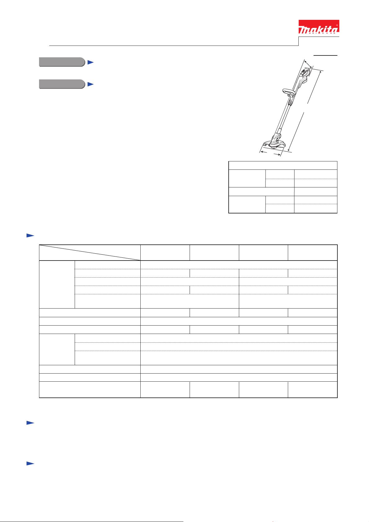
L
The image is
W
Dimensions: mm (")
Length (L)
Width (W)
Height (H)*
*1 The height varies depending on the angle of
the cutting head.
Li-ion
260 (10-1/4)
Bump & Feed
Single cord
190 (7-1/2)
minimum
maximum
minimum
1
maximum
UR140D
(RU01*1)
with DC18WA
160230
6,000
model UR140D.
1,229 (48-1/2)
1,433 (56-1/2)
267 (10-1/2)
186 (7-3/8)
257 (10-1/8)
UR180D
(RU02*
60
7,800
2.9 (6.4)2.9 (6.4)/ 3.1 (6.9)2.9 (6.3)/ 3.0 (6.7) 2.9 (6.3)
1)
Standard equipment
Nylon cutting head ............................... 1
Shoulder belt ....................................... 1
Note: The standard equipment for the tool shown above may vary by country.
Safety goggles ..................................... 1
15m Nylon cord ................................... 1
Optional accessories
Shoulder belt
Safety goggles
15m Nylon cord
30m Nylon cord
Spool set
Battery BL1415 (for BUR141)
Battery BL1430 (for BUR141)
Battery BL1815 (for BUR181)
Battery BL1830 (for BUR181)
Battery BL1411G (for UR140D)
Battery BL1811G (for UR180D)
Fast charger DC18RC (for BUR141, BUR181)
Charger DC18SD (for BUR141, BUR181)
Charger DC24SC (for BUR141, BUR181)
Automotive charger DC18SE (for BUR141, BUR181)
Charger DC18WA (for UR140D, UR180D)
Page 2

Variation list
P 2/ 12
BUR141 (LXRU01*
Model No.
BUR141Z --BUR141RH
BUR141SH
BUR141RF
BUR141SHE
BUR141RFE
LXRU01C
LXRU01
BUR181Z
BUR181RH
BUR181SH
BUR181SF
BUR181RF
BUR181RFE
LXRU02Z
LXRU021C
LXRU02C
LXRU02
UR140 (RU01*
Model No.
UR140DZ
UR140DW
RU01
UR180DZ
UR180DW
RU02Z
RU021
RU02
1)/ BUR181 (LXRU02*1)
Compatible
Battery
BL1415/
BL1430
DC18RA or DC18SD
BL1815/
BL1830
1)/ UR180 (RU02*1)
Compatible
Battery
BL1411G
BL1811G
Charger
--- --DC18RC
DC18SD
DC18RC
DC18SD
DC18RC
DC18RA
DC18RC
DC18SD
DC18RC
--- ---
DC18SD
DC18RA
Charger
--- ---
DC18WA
--- ---
DC18WA
--- ---
DC18WA
Battery
Type Q’ty
BL1415
BL1430
BL1415
BL1430
BL1415
BL1430
BL1815
BL1830
BL1815
BL1830
Battery
Type Q’ty
BL1411G
BL1811G
BL1811G
Battery
cover
1
---
2
------ ---
1
---
2
--- --1
---
2
Battery
cover
--- ---
---
1
2 1
--- --1 ---
--- --1
---
2 1
Housing
color
1
black
&
Makita blue
1
1
Housing
color
white
&
Makita blue
Note: All models also include the accessories listed in "Standard equipment" of page 1.
*1 Model numbers for North and Central American countries
Page 3
P 3/ 12
Repair
CAUTION: Repair the machine in accordance with “Instruction manual” or “Safety instructions”.
[1] NECESSARY REPAIRING TOOLS
Code No. Description Use for
1R022 Bearing plate Supporting Spool holder to remove Spur gear 48
1R217 Ring 22 Supporting Spur gear 48 to remove Gear shaft
1R236 Round Bar for Arbor 7-100 Removing Spool holder
1R286 Round Bar for Arbor 12-50 Supporting Spool holder to press-fit Gear shaft
[2] LUBRICATION
Apply Makita grease N. No.2 to the following portions designated with the black triangle to protect
parts and product from unusual abrasion.
Item No.
10
Fig. 1
Motor housing L Gear room where Spur gear 48 rotates 3 g
Description AmountPortion to lubricate
Motor housing R
DC motor
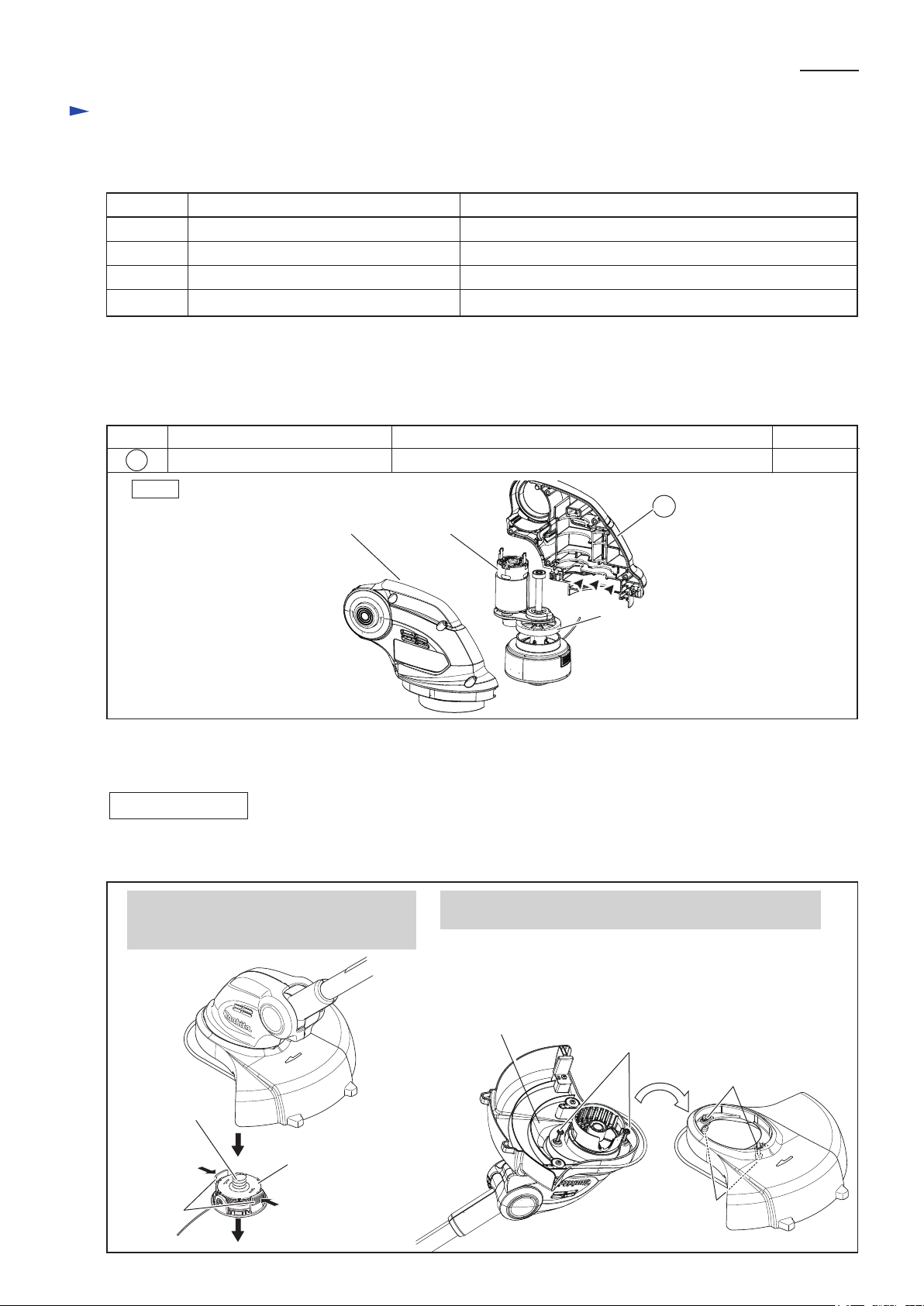
[3] DISASSEMBLY/ASSEMBLY
[3] -1. Gear shaft complete
DISASSEMBLING
(1) Remove Spool set and Safety cover as drawn in Fig. 2.
Fig. 2
10
Spur gear 48
1. While pressing the tabs, pull off Spool set.
Compression spring 17 is removed together
with Spool set.
Compression
spring 17
Spool set
Tabs of
Spool set
2. Loosen two M4x20 Pan head screws, and remove Safety
cover from Motor housing set.
Note: Each M4x20 Pan head screw has O ring 4 on the thread
to prevent losing. It is not necessary to separate M4x20
Pan head screws from Safety cover/ O rings 4.
Reverse side of
Safety cover
M4x20 Pan
head screw
(2 pcs.)
M4x20 Pan
head screw
(2 pcs.)
Each O ring 4 on the
thread of M4x20
Pan head screw
Page 4
Repair
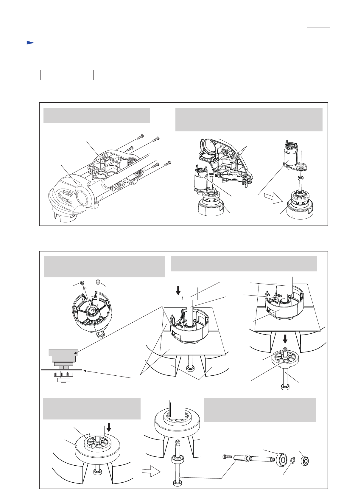
[3] DISASSEMBLY/ASSEMBLY
[3] -1. Gear shaft complete (cont.)
DISASSEMBLING
(2) After removing Motor housing R, Remove DC motor and Gear shaft complete as drawn in Fig. 3.
Fig. 3
P 4/ 12
3. Remove five 4x18 Tapping screws and
Motor housing R from Motor housing L.
4x18 Tapping screw (5 pcs.)
Motor housing R
Motor housing L
(3) Disassemble Gear shaft complete as drawn in Fig. 4.
Fig. 4
5. Remove M4x8 Pan head screw. And then,
install M4 Hex socket head bolt in preparation
of the next step.
M4x8 Pan
head screw
M4 Hex socket
head bolt
Spool holder
4. Remove Gear shaft complete together with DC motor.
And separate DC motor section from Gear shaft complete.
Note: Be careful not to lose Rubber pin 4.
Rubber pin 4
(2 pcs.)
DC motor
Gear shaft complete
6. Receive Spool holder with 1R022 and press M4 Hex
socket head bolt with 1R236. Spool holder is removed.
Arbor press
1R236
Receive the bottom of
Spool holder with 1R022.
7. Holding Spur gear 48 with 1R217,
press M4 Hex. socket head bolt on
Gear shaft. Spur gear 48 is removed.
Spur gear 48
1R 217
1R022
Arbor press table
8. Remove Ball bearing 696ZZ, Retaining
ring S-8, Ball bearing 608ZZ and M4 Hex.
socket head screw from Gear shaft.
Ball bearing 608ZZ
M4 Hex. socket
head screw
Gear shaft
Spool holder
M4 Hex socket
head bolt
Spur gear 48
Gear shaft
Ball bearing 696ZZ
Retaining ring S-8
Page 5

Repair
[3] DISASSEMBLY/ASSEMBLY
[3] -1. Gear shaft complete (cont.)
ASSEMBLING
(1) Assemble Gear shaft complete as drawn in Fig. 5.
Fig. 5
1. Press Gear shaft to Spur gear 48 as drawn below.
Press Ball bearing 608ZZ to Gear shaft and secure Ball bearing 608ZZ with Retaining ring S-8.
Press Ball bearing 696ZZ to Gear shaft.
Note: Be careful to the direction of Gear shaft.
P 5/ 12
Gear shaft
Step for Ball bearing 696ZZ
Groove for Retaining ring S-8
Step for Ball bearing 608ZZ
Knurling portion
Retaining ring S-8
Ball bearing 608ZZ
Ball bearing 696ZZ
Spur gear 48
2. Supporting Spool holder with 1R286,
press Gear shaft section to Spool holder.
1R286
3. Apply adhesive (ThreeBond 1342 or Locktite 242) to the thread of M4x8 Pan head screw when reusing it.
Replace M4 Hex socket head bolt to M4x8 Pan head screw with adhesive.
Note: Makita genuine M4x8 Pan head screw is thread locker screw.
Spool holder
Gear shaft
section
Compression spring 17
(2) Assemble Gear shaft complete to Motor housing in the reverse order of Disassembly. (refer to Fig. 3)
Note: Make sure that 2 pcs. of Rubber pin 4 are mounted to Motor housing (L).
[3] -2. DC motor
DISASSEMBLING
DC motor can be removed as drawn in Fig. 3.
No need to disassemble Spool set.
Note: Be careful not to lose Rubber pin 4.
ASSEMBLING
Assemble DC motor to Motor housing in the reverse order of disassembly. (Refer to Fig. 3)
Note: Make sure that 2 pcs. of Rubber pin 4 are mounted to Motor housing (L).
Page 6

Repair
[3] DISASSEMBLY/ASSEMBLY
[3] -3. Pipe section
DISASSEMBLING
(1) Remove Spool set and Safety cover as drawn in Fig. 2.
(2) Separate Motor housing (R) from Motor housing (L) as drawn in Fig. 3.
(3) Disassemble Pipe 25 complete as drawn in Fig. 6.
Fig. 6
P 6/ 12
1. Remove Lock off button B and
Compression spring 12.
Lock off button B
Compression spring 12
Pipe 25
3. Remove M6 Nut and M6x60 Hex bolt.
And remove Front grip.
M6 NutM6x60 Hex bolt
2. Remove Pipe holder (R) by unscrewing four 4x18 Tapping screws
and disconnect Lead wires (black, white) from DC motor.
Note: Be careful not to lose Rubber pin 6.
Pipe holder (R)
Rubber pin 6
4. While aligning the indicator (triangle) on
Lock sleeve to the just center of “Unlock”
and “Lock”, pull off it toward Pipe 25 side.
Pipe 25
Indicator (triangle)
on Lock sleeve
5. Remove Handle (R) from Handle (L) by unscrewing
eleven 4x18 Tapping screws.
Pull out Power supply cord unit from Pipe 25 complete.
Handle (R) complete
Pipe 25 complete
Pipe cap
Rubber sleeve 25
Power supply cord unit
Handle (L) complete
7. While pressing the projections
on the both sides of Pipe 25
complete, pull off Pipe cap
from Pipe 25 complete.
Lock sleeve
Symbol of
“Lock”
6. Remove Lock sleeve and Rubber sleeve 25.
Lock sleeve
Rubber sleeve 25
Projections of
Pipe cap
Pipe 25 complete
Pipe cap
Pipe 25
complete
Symbol of
“Unlock”
Pipe cap
Page 7

Repair
[3] DISASSEMBLY/ASSEMBLY
[3] -3. Pipe section (cont.)
ASSEMBLING
Assemble Pipe section as drawn in Figs. 7 and 8.
Fig. 7
P 7/ 12
1. Insert Pipe cap into Pipe 25 so that the square
projection of Pipe cap fits in the left side of
Pipe as drawn below.
Next, mount Rubber pipe 25 and Lock
sleeve 25 onto Pipe 25.
Lock sleeve
Rubber sleeve 25
Pipe 25
Caution label
Two holes
on the pipe end
close to caution
label
Hole on the pipe end
Left
Square projection
Fig. 8
Right
Pipe cap
2. Pass Power supply cord unit through Pipe 25.
Fit the square projection of Pipe cap into the inner groove of
Handle (L).
Set Rubber sleeve 25 in place of Handle (L).
Assemble Handle (R) to Handle (L).
Power supply
cord unit
Rubber sleeve 25
Pipe 25
Handle (L)
Caution label
Note: Face the caution label
upward as drawn in Fig. 8.
Square projection of
Pipe cap
Inner groove
as a guide rail for
Pipe 25 moving
Caution label faced upward
3. Mount Lock off button B to Pipe holder (R)
so that the notch aligns to the triangle mark
as drawn below.
Note:
are set in place.
Notch of Lock
off button B
Lock off button B
Make sure that 2 pcs. of Rubber pin 6
Caution Label
Triangle mark on
Pipe holder (R)
Rubber pin 6
(2 pcs.)
4. While aligning the triangle mark of Lock sleeve to
the symbol of “Unlock” on Handle (L), push Lock
sleeve toward Handle complete until it clicks.
And turn Lock sleeve until its triangle mark aligns
to the symbol of “Lock” on Handle (R).
Lock
sleeve
Symbol of
“Unlock”
Handle (L)
Triangle mark
Symbol
of “Lock”
Symbol of
“Lock”
Handle (R)
Page 8

Circuit diagram
Fig. D-1
Black
Red
Switch
UR140D, UR180D, BUR141, BUR181
Color index of lead wires' sheath
White
Yellow
Handle section
LED warning
This Lead wire is white
for some countries
instead of red.
Lamp
P 8/ 12
Orange
Pipe 25 section
Terminal
Controller
Power supply cord
Red dot mark
Motor
housing
DC
motor
Page 9

Wiring diagram
Fig. D-2
P 9/ 12
UR140D, UR180D, BUR141, BUR181
Wiring to DC motor
While facing the wire connecting portions to Motor housing (L) side,
connect Lead wire (red) receptacle to the terminal with Red dot mark
and Lead wire (black) receptacle to the other terminal.
Flag receptacles
Red dot mark
Wire connecting
portions
Fig. D-3
Room for Ball bearing 608ZZ
of Gear shaft complete
Motor housing
(L) side
Wiring in Motor housing L
1. Come out at least 5 mm long portion of Power supply cord unit
from the lower edge of Labyrinth figured lead holders.
2. Make sure that Power supply cord unit is fixed in Labyrinth
figured lead holders.
Labyrinth figured
lead holders
Power supply cord unit
(black, white)
at least 5 mm
Page 10

Wiring diagram
Fig. D-4
Lead wires for connecting to
Controller in Handle set
P 10/ 12
UR140D, UR180, BUR141, BUR181
Wiring in Pipe 25
1. Insert the long sheath side into Pipe 25 complete as drawn below.
Long sheath
Coil portion
Lead wires for connecting to
DC motor in Motor housing
Pipe 25 complete
2. Long sheath of Power supply cord unit
except the coil portion must be tight in
Pipe 25 complete.
Short
sheath
Coil portion
3. Be sure to check that Pipe 25 complete
can be smoothly pulled and pushed back.
Page 11

Wiring diagram
P 11/ 12
Fig. D-5
While facing the wire connecting portions
to Pipe 25 side, connect the Lead wires
(black, Yellow) to Terminal. And then,
connect Lead wire (red) to Terminal.
UR140D, UR180D
Wiring to Terminal
Lead wire
(black)
Pipe 25 side
Handle (L) side
Lead wire
(Yellow)
Wire connecting
portion
Lead wire
(red)
Terminal
Fig. D-6
Pass Lead wire (red) between Terminal and
Switch through the space between Rib A
and Rib B.
Rib A
Lead wire (red)
Wiring in Handle (L)
LED warning lamp
Switch
Put LED warning lamp’s lead wire (red)* on
its lead wire (black) and insert them into
the groove in Handle (L).
*using Lead wire (white) for some countries
Rib
Power supply cord unit
Rib
Sheath
at least
5 mm
Terminal
Rib B
1. Come out at least 5 mm long portion of
Power supply cord unit from the lower
edge of Labyrinth figured lead holders.
But the sheath end must not go over Rib A.
2. Make sure that Power supply cord unit is
fixed in Labyrinth figured lead holders.
Page 12

Wiring diagram
Fig. D-7
While facing the wire connecting portion
to Pipe 25 side, connect the Lead wire
(black) to Terminal. And then, connect Lead
wires (red, yellow) to Terminal.
UR141D, UR181D
Wiring to Terminal
Lead wire
(black)
Wire connecting portion
Pipe 25 side
P 12/ 12
Lead wire
(Yellow)
Lead wire
(red)
Terminal
Fig. D-8
LED warning lamp
Pass Lead wires (red, yellow) between Terminal
and Switch through the space between Rib A
and Rib B.
Pass Lead wire (yellow) through the space
between Rib A and Rib C.
Rib A
Lead wire (red)
Rib C
Terminal
Handle (L) side
Wiring in Handle (L)
Put LED warning lamp’s lead wire (red)* on
its lead wire (black) and insert them into
the groove in Handle (L).
*using Lead wire (white) for some countries
Switch
1. Come out at least 5 mm long portion of
Power supply cord unit from the lower
Rib B
edge of Labyrinth figured lead holders.
But the sheath end must not go over Rib A.
2. Make sure that Power supply cord unit is
fixed in Labyrinth figured lead holders.
Rib
Power supply cord unit
Sheath
Rib
at least
5 mm
 Loading...