

Page 1
GB
BUC250
UC250D
BUC300
UC300D
Cordless Chain Saw Instruction Manual
F
Tronçonneuse sans Fil Manuel d’instructions
D
Akku-Kettensäge Betriebsanleitung
I
Motosega a batteria Istruzioni per l’uso
NL
Accu-kettingzaag Gebruiksaanwijzing
E
Electrosierra Inalámbrica Manual de instrucciones
P
Motosserra a Bateria Manual de instruções
DK
Akku-kædesav Brugsanvisning
GR Αλυσοπρίονο µπαταρίασ Οδηγίεσ χρήσεωσ
Page 2
PARTS DESCRIPTION / DESCRIPTION DES PIÈCES / BESCHREIBUNG DER TEILE /
1
3
4
5
9
2
6
8
7
13
12
11
14
10
DESCRIZIONE DELLE PARTI / BESCHRIJVING VAN ONDERDELEN / DESCRIPCIÓN DE LAS PARTES /
DESCRIÇÃO DAS PEÇAS / BESKRIVELSE AF DELE / ΠΕΡΙΓΡΑΦΗ ΤΩΝ ΕΞΑΡΤΗΜΑΤΩΝ
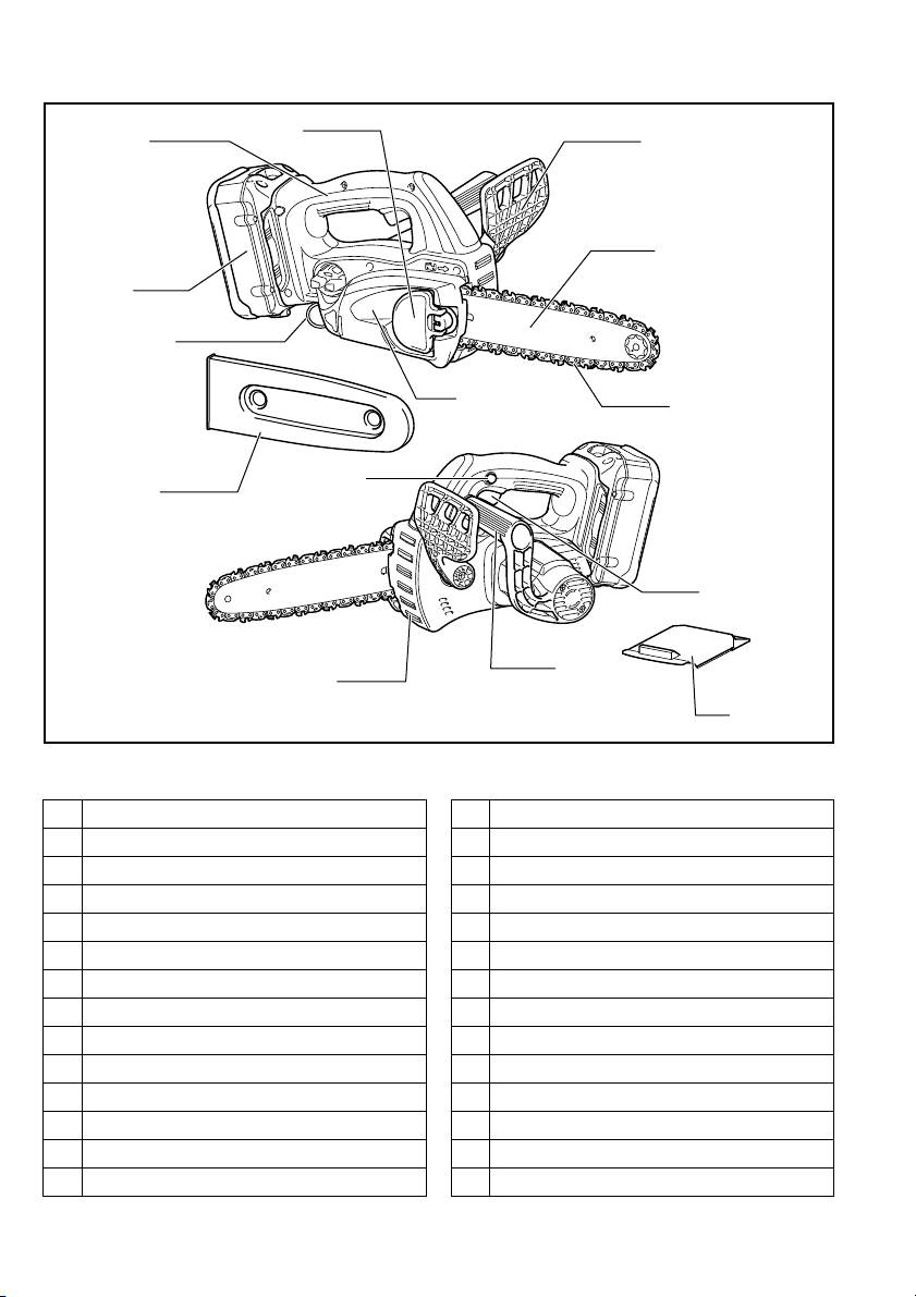
ENGLISH FRANÇAIS
1Lever
2 Front hand guard
3 Top handle
4 Battery cartridge
5 Carabiner or rope attachment point
6 Guide bar
7Saw chain
8 Sprocket cover
9Chain cover
10 Lock-off button
11 Switch trigger
12 Front handle
13 Serrated rail (claw stop)
14 Battery cover
2
013143
1Levier
2 Protège-main avant
3 Poignée supérieure
4 Batterie
5 Point de fixation du mousqueton ou de la corde
6 Guide de chaîne
7 Chaîne
8 Couvre-pignon
9 Cache de chaîne
10 Bouton de sécurité
11 Gâchette
12 Poignée avant
13 Rail dentelé (butée à griffe)
14 Couvercle de batterie
Page 3

DEUTSCH
1 Hebel
2 Vorderer Handschutz
3Obergriff
4 Akku
5 Befestigungsöse für Karabinerhaken oder Seil
6Schwert
7 Sägekette
8 Kettenraddeckel
9 Kettenabdeckung
10 Einschaltarretierung
11 Schalter
12 Frontgriff
13 Krallenanschlag (Klauenanschlag)
14 Akkuabdeckung
NEDERLANDS
1 Hendel
2 Beschermkap van voorhandgreep
3 Bovenhandgreep
4 Accu
5 Bevestigingsoog voor karabijnhaak of touw
6 Zaagblad
7 Zaagketting
8 Afdekking van kettingwiel
9 Kettingdeksel
10 Ontgrendelknop
11 Trekschakelaar
12 Voorhandgreep
13 Getande kam (klauwaanslag)
14 Deksel van de accu
ITALIANO
1Leva
2 Protezione mano anteriore
3 Manico superiore
4 Cartuccia batteria
5 Gancio o punto di attacco fune
6 Barra guida
7 Catena sega
8 Coperchio rocchetto
9 Coperchio catena
10 Bottone di sblocco
11 Interruttore a grilletto
12 Manico anteriore
13 Guida dentata (fermo dente)
14 Coperchio batteria
ESPAÑOL
1Baja
2 Protector de la mano delantera
3 Empuñadura principal
4 Cartucho de batería
5 Punto de sujeción de mosquetón o cuerda
6 Placa de guía
7 Cadena de sierra
8 Cubierta del piñón
9 Cubierta de la cadena
10 Botón de seguro
11 Gatillo interruptor
12 Empuñadura delantera
13 Riel dentado (tope de gancho)
14 Tapa de la batería
3
Page 4

PORTUGUÊS
1 Alavanca
2 Protector frontal das mãos
3 Pega superior
4 Bateria
5 Ponto de fixação da corda ou gancho
6 Espada
7 Corrente da electroserra
8 Cobertura da roda dentada
9 Cobertura da corrente
10 Botão de bloqueio
11 Gatilho do interruptor
12 Pega frontal
13 Trilho dentado (retentor de garras)
14 Tampa da bateria
DANSK
1Arm
2 Frontkappe
3 Tophåndtag
4 Akku
5 Fastgørelsespunkt til karabinhage eller reb
6Sværd
7 Savkæde
8 Kædehjulsdæksel
9 Kædedæksel
10 Låseknap
11 Afbryderknap
12 Fronthåndtag
13 Takket kant (hage-stop)
14 Batteridæksel
ΕΛΛΗΝΙΚΑ
1 Μοχλς
2 Μπροστινς προφυλακτήρας χεριών
3 Άνω λαβή
4 Κασετίνα μπαταρίας
5 Carabiner ή σημείο πρσδεσης σχοινιού
6 Κατευθυντήρια λάμα
7 Αλυσίδα πριονιού
8 Κάλυμμα οδοντωτού τροχού
9 Κάλυμμα αλυσίδας
10 Πλήκτρο ασφάλειας
11 Σκανδάλη διακπτης
12 Μπροστινή λαβή
13 Οδοντωτή ράγα (στοπ σιαγνας)
14 Κάλυμμα μπαταρίας
4
Page 5
12
10
4
5
9
78
6
10
4
5
9
78
6
1
2
3
010918
011445
34
56
78
010939 011459
11
11
12
12
011715011458
15
17
18
18
17
13
13
14
14
011452 011450
15
16
16
5
Page 6
22
15
16
15
22
27
26
18
24
25
2 - 4 mm
23
21
19
15
16
20
910
11 12
13 14
010931
010933
011453
010932
011451
011454
15 16
6
011455
011456
Page 7
17 18
29
31
1
2
40
3
2
29
28
30
2
28
37
36
39
38
32
33
34
35
011457
011636
19 20
21 22
23 24
011229 011585
010940010920
010921 008576
7
Page 8
25 26
45
o
2 1/2
45
o
41
A
B
A
B
001742
010922
27 28
29 30
010941
006915
31 32
8
006917
006914
010942
006918
Page 9
33 34
48
49
45
3
46
47
42
43
43
44
44
006923
009202
35 36
37 38
39 40
011446 008633
006929011075
010924 011447
9
Page 10
41 42
52
53
51
50
19
19
50
011448
010927
43 44
45
010928
011449
001145
10
Page 11
Symbols
The followings show the symbols used for the equipment. Be sure that you understand their meaning before use.
Symboles
Nous donnons ci-dessous les symboles utilisés pour l’outil. Assurez-vous que vous en avez bien compris la signification avant d’utiliser l’outil.
Symbole
Die folgenden Symbole werden für die Maschine verwendet. Machen Sie sich vor der Benutzung unbedingt mit ihrer
Bedeutung vertraut.
Simboli
Per questo utensile vengono usati i simboli seguenti. Bisogna capire il loro significato prima di usare l’utensile.
Symbolen
Voor dit gereedschap worden de volgende symbolen gebruikt. Zorg ervoor dat u de betekenis van deze symbolen
begrijpt alvorens het gereedschap te gebruiken.
Símbolos
A continuación se muestran los símbolos utilizados con esta herramienta. Asegúrese de que entiende su significado
antes de usarla.
Símbolos
O seguinte mostra os símbolos utilizados para a ferramenta. Certifique-se de que compreende o seu significado antes
da utilização.
Symboler
Nedenstående symboler er anvendt i forbindelse med denne maskine. Vær sikker på, at De har forstået symbolernes
betydning, før maskinen anvendes.
Σύµβολα
Τα ακλουθα δείχνουν τα σύμβολα που χρησιμοποιούνται για το μηχάνημα. Βεβαιωθείτε τι καταλαβαίνετε
τη σημασία τους πριν απ τη χρήση.
END005-5
• Read instruction manual.
• Lire le mode d’emploi.
• Bitte Bedienungsanleitung lesen.
• Leggete il manuale di istruzioni.
• Lees de gebruiksaanwijzing.
• Lea el manual de instrucciones.
• Leia o manual de instruções.
• Læs brugsanvisningen.
• Διαβάστε τις οδηγίες χρήσης.
• Wear eye protection.
• Portez une protection pour les yeux.
• Eine Schutzbrille tragen.
• Indossare gli occhiali di protezione.
• Draag oogbescherming.
• Póngase protección para los ojos.
• Utilize protectores para os olhos.
• Brug øjenbeskyttelse.
• Να φοράτε προστατευτικά ματιών.
11
Page 12

• Wear ear protection.
• Portez une protection pour les oreilles.
• Einen Gehörschutz tragen.
• Indossare la protezione delle orecchie.
• Draag gehoorbescherming.
• Póngase protección para los oídos.
• Utilize protectores para os ouvidos.
• Brug høreværn.
• Να φοράτε προστατευτικά αυτιών.
• Wear a helmet, goggles and ear protection.
• Portez un casque, des lunettes de sécurité et une protection pour les oreilles.
• Tragen Sie einen Helm, eine Schutzbrille und einen Gehörschutz.
• Indossare il casco, gli occhiali di protezione e i paraorecchi.
• Draag een veiligheidshelm, veiligheidsbril en oorbescherming.
• Póngase casco, gafas de seguridad y protección para los oídos.
• Use um capacete, óculos de segurança e protectores para os ouvidos.
• Bær hjelm, sikkerhedsbriller og høreværn.
• Να φοράτε κράνς και μέσα προστασίας ρασης και ακής.
• Do not expose to rain.
• N’exposez pas l’outil à la pluie.
• Die Maschine keinem Regen aussetzen.
• Non esporre alla pioggia.
• Stel het gereedschap niet bloot aan regen.
• No exponga a la lluvia.
• Não exponha a ferramenta à chuva.
• Udsæt ikke saven for regn.
• Να μην εκτίθεται στη βροχη.
12
Page 13
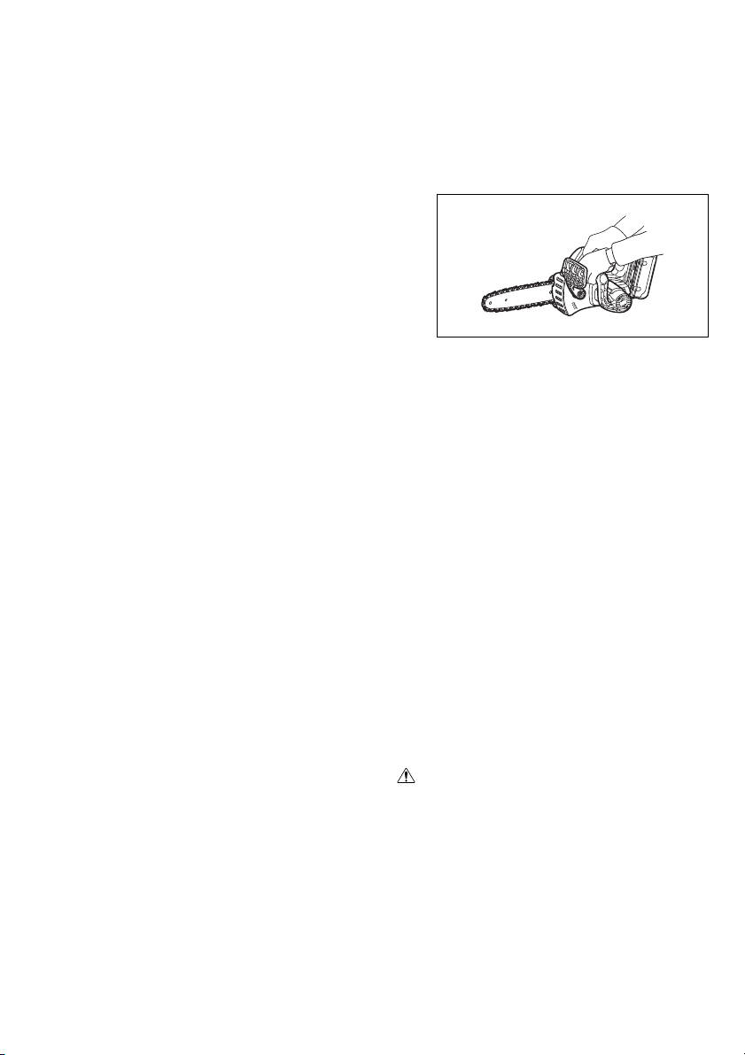
• Hold the saw with both hands while working! One-handed use is extremely hazardous!
• Tenez la scie fermement à deux mains pendant que vous travaillez ! L’utilisation avec une
seule main est extrêmement dangereuse !
• Die Säge während der Arbeit mit beiden Händen halten! Einhändiger Betrieb ist äußerst
gefährlich!
• Tenere la sega con entrambe le mani durante il lavoro! L’uso con una sola mano è estremamente pericoloso!
• Houd de kettingzaag tijdens het werk met beide handen vast! Gebruik met slechts één hand
is uitermate gevaarlijk.
• ¡Sujete la sierra con ambas manos mientras realiza el trabajo! ¡La utilización una sola mano
es muy peligroso!
• Segure a electroserra com as duas mãos ao trabalhar. É muito perigoso segurá-la só com
uma mão.
• Hold i saven med begge hænder under arbejdet! Anvendelse med kun den ene hånd på
saven er yderst farligt!
• Να κρατάτε τ αλυσοπρίονο με τα δύο χέρια στη διάρκεια της εργασίας! Η χρήση με το
χένα έρι είναι εξαιρετικά επικίνδυνη!
• Usable with the battery converter BCV02
• Peut être utilisé avec le convertisseur de batterie BCV02
• Verwendbar mit Akku-Adapter BCV02
• Utilizzabile con il convertitore batteria BCV02
• Te gebruiken met de accudraaghouder BCV02
• Se puede utilizar con el convertidor de baterías BCV02
• Utilizável com o conversor de bateria BCV02
• Brugbar med akku-konverteren BCV02
• Χρησιμοποιείται με τον μετατροπέα μπαταριών BCV02
• Maximum permissible cut length
• Longueur de coupe maximale admise
• Höchstzulässige Schnittlänge
• Lunghezza di taglio massima permissibile
• Maximaal toegestane zaaglengte
• Longitud de corte permitida máxima
• Comprimento máximo de corte permitido
• Maks. tilladt skærelængde
• Μέγιστο επιτρεπομενο μήκος κοπής
13
Page 14
• Direction of chain travel
Cd
Ni-MH
Li-ion
• Sens de progression de la chaîne
• Kettenumlaufrichtung
• Direzione di corsa catena
• Draairichting van de ketting
• Dirección de desplazamiento de la cadena
• Sentido de movimento da corrente
• Retning af kædens bevægelse
• Κατεύθυνση διαδρομής αλυσίδας
• Saw chain oil adjustment
• Réglage d’huile de la chaîne
• Sägekettenöleinstellung
• Regolazione olio catena sega
• Afstelling voor zaagkettingolie
• Ajuste del aceite de la cadena de sierra
• Regulação da lubrificação da corrente da electroserra
• Justering af savkædeolie
• Ρύθμιση λίπανσης αλυσίδας αλυσοπρίονου
• Only for EU countries
Do not dispose of electric equipment or battery pack together with household waste material!
In observance of European Directive 2002/96/EC on waste electric and electronic equipment, 2006/
66/EC on batteries and accumulators and waste batteries and accumulators and their implementation in accordance with national laws, electric equipment and battery pack that have reached the
end of their life must be collected separately and returned to an environmentally compatible recycling facility.
• Uniquement pour les pays de l’UE
Ne pas jeter les appareils électriques et les batteries avec les ordures ménagères !
Conformément aux directives européennes 2002/96/CE (relative aux déchets d’équipements électriques et électroniques) et 2006/66/CE (relative aux piles et accumulateurs ainsi qu’aux déchets de
piles et accumulateurs), ainsi qu’à leur application en conformité avec les lois nationales, les appareils électriques et batteries qui ont atteint la fin de leur durée de service doivent être collectés
séparément et renvoyés à un établissement de recyclage respectueux de l’environnement.
• Nur für EG-Länder
Werfen Sie Elektrogeräte oder Akkus nicht in den Hausmüll!
Gemäß der Europäischen Richtlinie 2002/96/EG über Elektro- und Elektronik-Altgeräte, 2006/66/
EG über Batterien, Akkus sowie verbrauchte Batterien und Akkus und ihre Umsetzung gemäß den
Landesgesetzen müssen Elektrogeräte und Akkus, die das Ende ihrer Lebensdauer erreicht haben,
getrennt gesammelt und einer umweltgerechten Recycling-Einrichtung zugeführt werden.
• Soltanto per i Paesi dell’unione europea
Questo apparecchio elettrico o la batteria non devono essere gettati via con i rifiuti domestici.
In osservanza alla Direttiva Europea 2002/96/CE sugli apparecchi elettrici ed elettronici di scarto,
2006/66/CE sulle batterie e gli accumulatori, e sulle batterie e gli accumulatori esausti, e la sua
implementazione secondo le leggi locali, gli apparecchi elettrici e le batterie che hanno raggiunto la
fine della loro vita di servizio devono essere raccolti separatamente e portati in un centro di smaltimento ecocompatibile.
14
Page 15

• Alleen voor EU-landen
Geef elektrisch gereedschap of accu’s niet met het huisvuil mee!
Volgens de Europese richtlijn 2002/96/EC inzake oude elektrische en elektronische apparaten, richtlijn 2006/66/EC inzake batterijen en accu's en wegwerpbatterijen, en de toepassing daarvan binnen de nationale wetgeving, dienen gebruikte elektrisch apparaten en accu's die het einde van hun
levensduur hebben bereikt, gescheiden te worden ingezameld en te worden afgevoerd naar een
recyclebedrijf dat voldoet aan de geldende milieu-eisen.
• Sólo para países de la Unión Europea
¡No tire aparatos eléctricos ni baterías a la basura con los residuos domésticos!
En conformidad con la Directiva Europea 2002/96/EC sobre residuos de aparatos eléctricos y electrónicos y la Directiva Europea 2006/66/EC sobre baterías y acumuladores y residuos de baterías y
de acumuladores y su aplicación de acuerdo con la legislación nacional, los aparatos eléctricos y
las baterías cuya vida útil haya llegado a su fin se deberán recoger por separado y trasladar a una
planta de reciclaje que cumpla con las exigencias ecológicas.
• Apenas para os países da União Européia
Não deite equipamentos eléctricos nem baterias no lixo doméstico!
De acordo com as directivas europeias 2002/96/CE sobre ferramentas eléctricas e electrónicas
usadas e 2006/66/CE sobre baterias e acumuladores e respectivos resíduos e a implementação
dessas directivas conforme a lei nacional, as ferramentas eléctricas e as baterias que atingem o fim
de sua vida útil devem ser recolhidas em separado e encaminhadas a uma instalação de reciclagem compatível com os regulamentos sobre o meio ambiente.
• Gælder kun lande i EU
Undlad at bortskaffe elektrisk udstyr eller akkuer sammen med almindeligt husholdningsaffald.
I henhold til EU-direktiv 2002/96/EC angående brugt elektrisk og elektronisk udstyr, 2006/66/EC
angående batterier og akkumulatorer og brugte batterier og iværksættelse af bortskaffelse af batterier og akkumulatorer i overensstemmelse med nationale love, skal elektrisk udstyr og akkuer, der
har nået slutningen af deres levetid, indsamles separat og afhændes til en genbrugsfacilitet, som er
miljømæssigt kompatibel.
• Μνο για χώρες ΕΕ
Μην απορρίπτετε ηλεκτρικ εξοπλισμ ή μπαταρίες μαζί με τα οικιακά απβλητα!
Σύμφωνα με την Ευρωπαϊκή Οδηγία 2002/96/ΕΚ περί αποβλήτων ειδών ηλεκτρικού και
ηλεκτρονικού εξοπλισμού και την Οδηγία 2006/66/EΚ περί μπαταριών και συσσωρευτών και
αποβλήτων μπαταριών και συσσωρευτών και την εφαρμογή τους σύμφωνα με την εθνική
νομοθεσία, απαιτείται συλλογή του ηλεκτρικού εξοπλισμού και των μπαταριών, το ριο
ζωής των οποίων έχει λήξει, ξεχωριστά και επιστροφή τους σε εγκατάσταση ανακύκλωσης
συμβατή με την προστασία του περιβάλλοντος.
15
Page 16

ENGLISH (Original instructions)
Explanation of general view
1 Red indicator
2Button
3 Battery cartridge
4 Lock-off button
5 Switch trigger
6 Front hand guard
7Lock
8 Unlock
9 Adjusting screw
10 Carabiner
(rope attachment point)
11 Indicator lamps
12 CHECK button
13 Slightly slide
14 Move in the upright position
15 Press in
16 Loosen
17 Sprocket cover
18 Adjusting dial
19 Sprocket
SPECIFICATIONS
Model BUC250 UC250D BUC300 UC300D
Chain speed per minute 8.3 m/s (500 m/min) 8.3 m/s (500 m/min)
Length of guide bar 250 mm 250 mm 300 mm 300 mm
Guide bar type
Type 91VG/91PX 25AP 91VG/91PX 25AP 90SG 90SG
Saw chain
Pitch3/8”1/4”3/8”1/4”3/8”3/8”
No. of drive
links
Number of teeth696966
Overall length 576 mm 589 mm 577 mm 590 mm 626 mm 627 mm
Net weight 4.5 kg 4.5 kg 4.6 kg 4.6 kg
Rated voltage D.C. 36 V D.C. 36 V D.C. 36 V D.C. 36 V
• Weight, with battery cartridge, according to EPTA-Pro-
cedure 01/2003
Intended use
The tool is intended for cutting branches.
General Power Tool Safety Warnings
WARNING Read all safety warnings and all
instructions. Failure to follow the warnings and
instructions may result in electric shock, fire and/or
serious injury.
Save all warnings and instructions for future reference.
20 Adjusting pin
21 Small hole
22 Tighten
23 Lever
24 Low
25 High
26 Guide bar
27 Saw chain
28 Adapter
29 Hook
30 Tool
31 Belt
32 Arm cord hook band
33 Holder
34 Extension cord (Battery
adapter)
35 Adapter (Battery adapter)
36 Oil tank cap
37 Oil tank opening
Sprocket
nose bar
Carving bar
Sprocket
nose bar
38 Oil inspection window
(for refilling the tank with oil)
39 Oil inspection window
40 Lower guide
41 Felling area
42 Felling direction
43 Danger zone
44 Escape route
45 Scabbard (chain cover)
46 File forward stroke
47 1/5 of the file diameter
48 Small dust or particles
49 Slotted bit screwdriver
50 Locking ring
51 Limit mark
52 Brush holder cap
53 Screwdriver
8.3 m/s
(500 m/min)
Carving bar
Sprocket
nose bar
40 60 40 60 46 46
ENE031-2
GEA010-1
CORDLESS CHAIN SAW SAFETY WARNINGS:
1. Keep all parts of the body away from the saw
chain when the chain saw is operating. Before
you start the chain saw, make sure the saw chain
is not contacting anything. A moment of inatten-
tion while operating chain saws may cause entanglement of your clothing or body with the saw chain.
2. Always hold the chain saw with your right hand
on the rear handle and your left hand on the
front handle. Holding the chain saw with a reversed
hand configuration increases the risk of personal
injury and should never be done.
3. Hold the power tool by insulated gripping surfaces only, because the saw chain may contact
hidden wiring. Saw chains contacting a “live” wire
may make exposed metal parts of the power tool
“live” and could give the operator an electric shock.
8.3 m/s
(500 m/min)
Sprocket
nose bar
GEB071-6
16
Page 17
4. Wear safety glasses and hearing protection. Further protective equipment for head, hands, legs
and feet is recommended. Adequate protective
clothing will reduce personal injury by flying debris
or accidental contact with the saw chain.
5. Do not operate a chain saw in a tree. Operation of
a chain saw while up in a tree may result in personal
injury.
6. Always keep proper footing and operate the
chain saw only when standing on fixed, secure
and level surface. Slippery or unstable surfaces
such as ladders may cause a loss of balance or control of the chain saw.
7. When cutting a limb that is under tension be
alert for spring back. When the tension in the wood
fibres is released the spring loaded limb may strike
the operator and/or throw the chain saw out of control.
8. Use extreme caution when cutting brush and
saplings. The slender material may catch the saw
chain and be whipped toward you or pull you off balance.
9. Carry the chain saw by the front handle with the
chain saw switched off and away from your body.
When transporting or storing the chain saw
always fit the guide bar cover. Proper handling of
the chain saw will reduce the likelihood of accidental
contact with the moving saw chain.
10. Follow instructions for lubricating, chain tensioning and changing accessories. Improperly
tensioned or lubricated chain may either break or
increase the chance for kickback.
11. Keep handles dry, clean, and free from oil and
grease. Greasy, oily handles are slippery causing
loss of control.
12. Cut wood only. Do not use chain saw for purposes not intended. For example: do not use
chain saw for cutting plastic, masonry or nonwood building materials. Use of the chain saw for
operations different than intended could result in a
hazardous situation.
13. Causes and operator prevention of kickback:
Kickback may occur when the nose or tip of the
guide bar touches an object, or when the wood
closes in and pinches the saw chain in the cut.
Tip contact in some cases may cause a sudden
reverse reaction, kicking the guide bar up and back
towards the operator.
Pinching the saw chain along the top of the guide
bar may push the guide bar rapidly back towards the
operator.
Either of these reactions may cause you to lose control of the saw which could result in serious personal
injury. Do not rely exclusively upon the safety
devices built into your saw. As a chain saw user, you
should take several steps to keep your cutting jobs
free from accident or injury.
Kickback is the result of tool misuse and/or incorrect
operating procedures or conditions and can be
avoided by taking proper precautions as given
below:
- Maintain a firm grip, with thumbs and fingers
encircling the chain saw handles, with both
hands on the saw and position your body and
arm to allow you to resist kickback forces.
Kickback forces can be controlled by the operator,
if proper precautions are taken. Do not let go of
the chain saw.
011443
- Do not overreach and do not cut above shoul-
der height. This helps prevent unintended tip
contact and enables better control of the chain
saw in unexpected situations.
- Only use replacement bars and chains speci-
fied by the manufacturer. Incorrect replacement
bars and chains may cause chain breakage and/
or kickback.
- Follow the manufacturer’s sharpening and
maintenance instructions for the saw chain.
Decreasing the depth gauge height can lead to
increased kickback.
14. Before starting work, check that the chain saw is in
proper working order and that its condition complies
with the safety regulations. Check in particular that:
• The chain brake is working properly;
• The run-down brake is working properly;
• The bar and the sprocket cover are fitted correctly;
• The chain has been sharpened and tensioned in
accordance with the regulations;
15. Do not start the chain saw with the chain cover
being installed on it. Starting the chain saw with
the chain cover being installed on it may cause the
chain cover to thrown out forward resulting in personal injury and damage to objects around the operator.
SAVE THESE INSTRUCTIONS.
WARNI NG:
DO NOT let comfort or familiarity with product
(gained from repeated use) replace strict adherence
to safety rules for the subject product. MISUSE or
failure to follow the safety rules stated in this instruction manual may cause serious personal injury.
17
Page 18

ENC007-7
IMPORTANT SAFETY INSTRUCTIONS
FOR BATTERY CARTRIDGE
1. Before using battery cartridge, read all instructions and cautionary markings on (1) battery
charger, (2) battery, and (3) product using battery.
2. Do not disassemble battery cartridge.
3. If operating time has become excessively
shorter, stop operating immediately. It may
result in a risk of overheating, possible burns
and even an explosion.
4. If electrolyte gets into your eyes, rinse them out
with clear water and seek medical attention right
away. It may result in loss of your eyesight.
5. Do not short the battery cartridge:
(1) Do not touch the terminals with any conduc-
tive material.
(2) Avoid storing battery cartridge in a container
with other metal objects such as nails, coins,
etc.
(3) Do not expose battery cartridge to water or
rain.
A battery short can cause a large current flow,
overheating, possible burns and even a breakdown.
6. Do not store the tool and battery cartridge in
locations where the temperature may reach or
exceed 50°C (122°F).
7. Do not incinerate the battery cartridge even if it
is severely damaged or is completely worn out.
The battery cartridge can explode in a fire.
8. Be careful not to drop or strike battery.
9. Do not use dropped or struck battery.
SAVE THESE INSTRUCTIONS.
Tips for maintaining maximum battery life
1. Charge the battery cartridge before completely
discharged.
Always stop tool operation and charge the battery cartridge when you notice less tool power.
2. Never recharge a fully charged battery cartridge.
Overcharging shortens the battery service life.
3. Charge the battery cartridge with room temperature at 10°C – 40°C (50°F – 104°F). Let a hot battery cartridge cool down before charging it.
4. Charge the battery cartridge once in every six
months if you do not use it for a long period of
time.
FUNCTIONAL DESCRIPTION
CAUTION:
• Always be sure that the tool is switched off and the battery cartridge is removed before adjusting or checking
function on the tool.
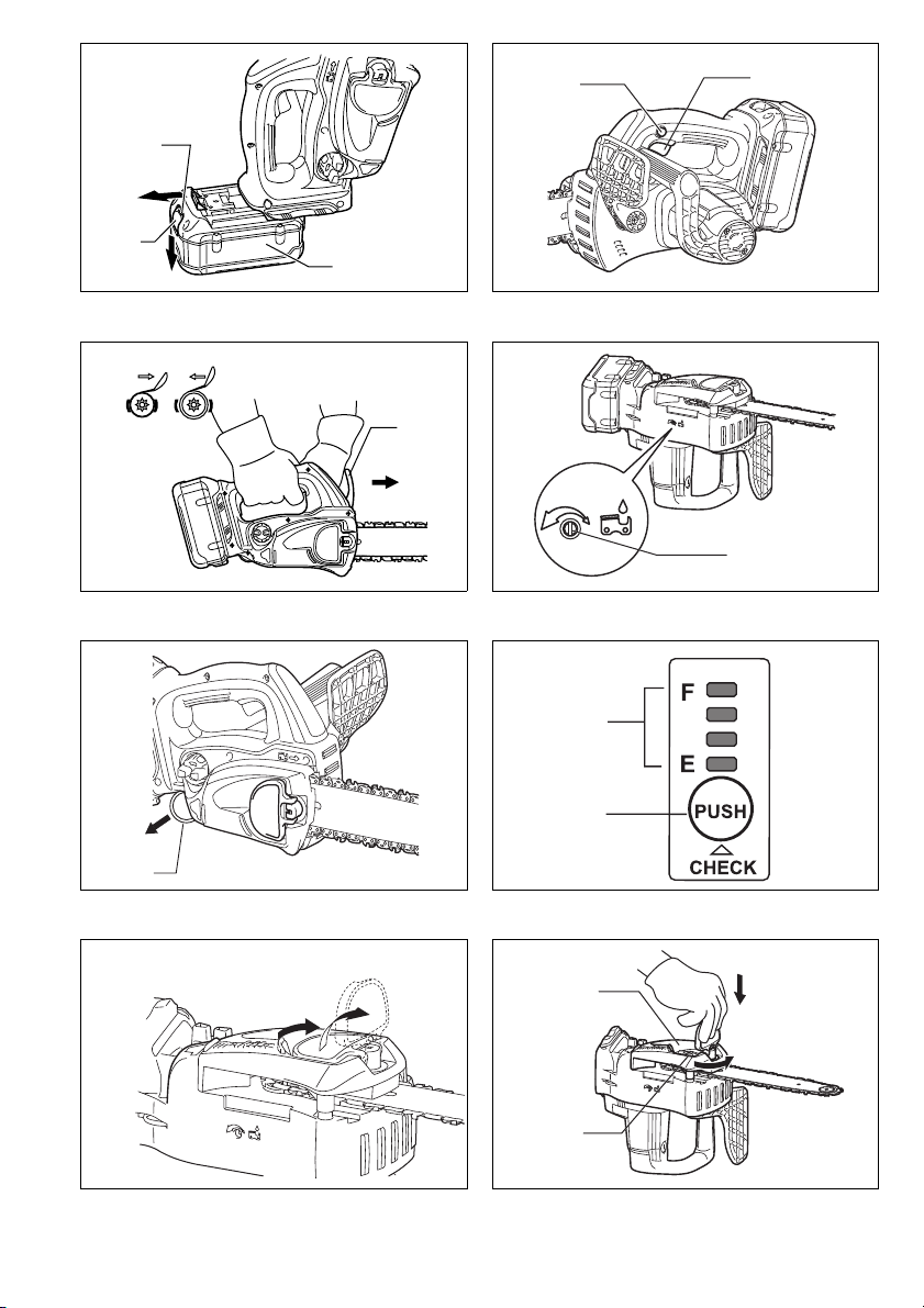
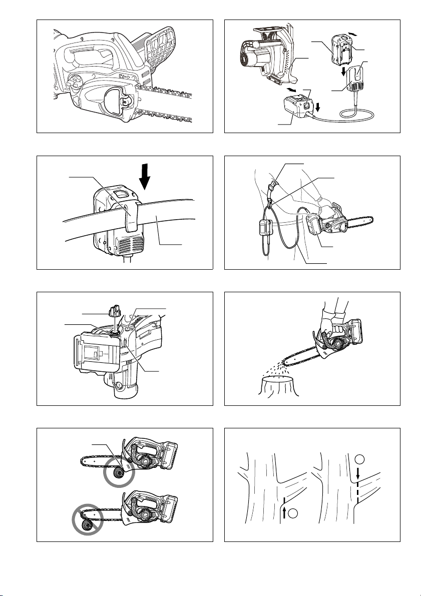
Installing or removing battery cartridge (Fig. 1)
CAUTION:
• Always switch off the tool before installing or removing
of the battery cartridge.
• Hold the tool and the battery cartridge firmly when
installing or removing battery cartridge.
Failure to hold the tool and the battery cartridge firmly
may cause them to slip off your hands and result in
damage to the tool and battery cartridge and a personal injury.
To remove the battery cartridge, slide it from the tool
while sliding the button on the front of the cartridge.
To install the battery cartridge, align the tongue on the
battery cartridge with the groove in the housing and slip it
into place. Insert it all the way until it locks in place with a
little click. If you can see the red indicator on the upper
side of the button, it is not locked completely.
CAUTION:
• Always install the battery cartridge fully until the red
indicator cannot be seen. If not, it may accidentally fall
out of the tool, causing injury to you or someone
around you.
• Do not install the battery cartridge forcibly. If the cartridge does not slide in easily, it is not being inserted
correctly.
Switch action (Fig. 2)
CAUTION:
• Before installing the battery cartridge into the tool,
always check to see that the switch trigger actuates
properly and returns to the “OFF” position when
released.
To prevent the switch trigger from being accidentally
pulled, a lock-off button is provided.
To start the tool, depress the lock-off button and pull the
switch trigger. Release the switch trigger to stop.
Checking the chain brake (Fig. 3)
NOTE:
• If the chain saw fails to start, the chain brake must be
released. Pull the front hand guard backwards firmly
until you feel it engage.
Hold the chain saw with both hands when switching it on.
Hold the top handle with your right hand, the front handle
with your left. The bar and the chain must not be in contact with any object.
First press the lock-off button, then the switch trigger.
The saw chain starts immediately.
Press the front hand guard forwards using the back of
your hand. The saw chain must come to an immediate
standstill.
CAUTION:
• Should the saw chain not stop immediately when this
test is performed, the saw may not be used under any
circumstances. Consult a MAKITA specialist repair shop.
18
Page 19
Checking the run-down brake
Switch on the chain saw.
Release the switch trigger completely. The saw chain
must come to a standstill within one second.
CAUTION:
• Should the saw chain not come to a stop within one
second when this test is performed, the saw must not
be used. Consult a MAKITA specialist repair shop.
Adjusting the chain lubrication (Fig. 4)
You can adjust the oil pump feed rate with the adjusting
screw. The amount of oil can be adjusted using the universal wrench.
Carabiner (rope attachment point) (Fig. 5)
Carabiner (Rope attachment point) is for use of tool
hanging. Before using carabiner, pull it out and tie it with
a rope.
Battery protection system
Lithium-ion batteries are equipped with a protection system. This system automatically cuts off power to the tool
to extend battery life.
The tool will automatically stop during operation if the
tool and/or battery are placed under one of the following
conditions:
• Overloaded:
The tool is operated in a manner that causes it to draw
an abnormally high current.
In this situation, release the switch trigger on the tool
and stop the application that caused the tool to become
overloaded. Then pull the switch trigger again to
restart.
If the tool does not start, the battery is overheated. In
this situation, let the battery cool before pulling the
switch trigger again.
• Low battery voltage:
The remaining battery capacity is too low and the tool
will not operate. In this situation, remove and recharge
the battery.
Battery remaining capacity indicator (only for
models with Battery BL3622A)
Battery BL3622A is equipped with the battery remaining
capacity indicator. (Fig. 6)
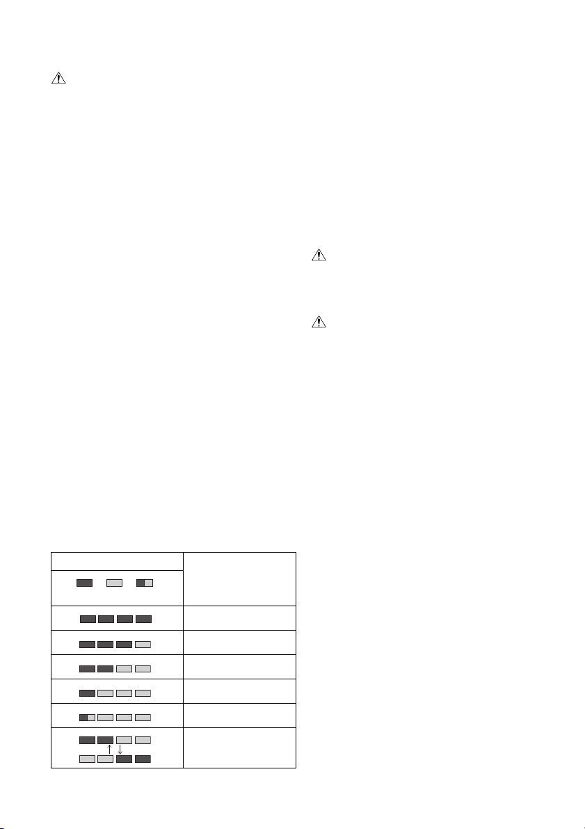
Press the CHECK button to indicate the battery remaining capacity. The indicator lamps will then light for
approx. three seconds.
Indicator lamps
F
Remaining capacity
70% to 100%
45% to 70%
20% to 45%
0% to 20%
Charge the battery.
Lighted
E
Off
Blinking
• When only the lowermost indicator lamp (next to the
“E”) blinks, or when none of the indicator lamps light,
the battery charge has run out, so the tool does not
operate. In these cases, charge the battery or replace
the empty battery with a fully charged one.
• When two or more indicator lamps do not light even
after charging is complete, the battery has reached the
end of its service life.
• When the upper two and lower two indicator lamps light
alternately, the battery may have malfunctioned. Contact your local Makita authorized service center.
NOTE:
• The indicated charge may be lower than the actual
level during use or immediately after using the tool.
• Depending on the conditions of use and the ambient
temperature, the indication may differ slightly from the
actual capacity.
ASSEMBLY
CAUTION:
• Always be sure that the tool is switched off and the battery cartridge is removed before carrying out any work
on the tool.
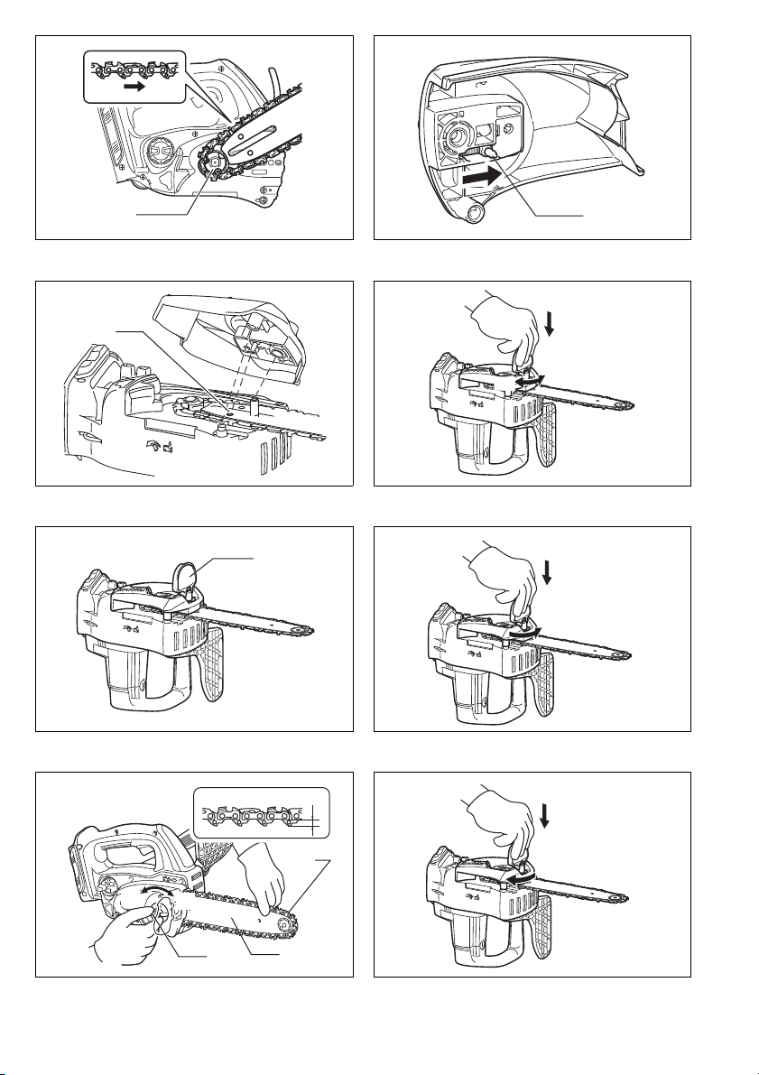
Installing or removing saw chain
CAUTION:
• Always be sure that the tool is switched off and the battery cartridge is removed before installing or removing
the saw chain.
• Always wear gloves when installing or removing the
saw chain.
1. To remove the saw chain, slightly slide the lever in
the direction of arrow so that it can be released from
the locked position and move the lever in the upright
position as shown in the figure. (Fig. 7)
2. Press the lever and with the lever pressed in, turn it
counterclockwise to loosen the nut until sprocket
cover comes off. (Pressing in the lever leads to the
fitting of lever into the nut.) (Fig. 8)
3. Turn the adjusting dial counterclockwise to release
the saw chain tension.
4. Remove the sprocket cover.
5. Remove the saw chain and guide bar from the chain
saw.
6. To install the saw chain, fit in one end of the saw
chain on the top of the guide bar and the other end
of it around the sprocket. (Fig. 9)
At this time, fit the saw chain as shown in the figure
because it rotates in the direction of arrow.
7. Rest the guide bar in place on the chain saw.
8. Turn the adjusting dial counterclockwise to slide the
adjusting pin in the direction of arrow. (Fig. 10)
9. Place the sprocket cover on the chain saw so that
the adjusting pin is positioned in a small hole in the
guide bar. (Fig. 11)
10. Press in the lever and with the lever depressed turn
it fully clockwise to tighten the nut. Then make it
about a quarter turn counterclockwise to loosen the
nut lightly. (Fig. 12)
011713
The battery may have
malfunctioned.
19
Page 20

Adjusting saw chain tension
The saw chain may become loose after many hours of
use. From time to time check the saw chain tension
before use. (Fig. 13)
Move the lever in the upright position.
Press in the lever. With the lever depressed, make a
quarter turn on it counterclockwise to loosen the nut
lightly. (Pressing in the lever leads to the fitting of lever
into the nut.) (Fig. 14)
Turn the adjusting dial to adjust saw chain tension. Grasp
the saw chain in the middle of the guide bar and lift up.
The gap between the guide bar and the tie strap of the
saw chain should be approx. 2 – 4 mm. If the gap is not
approx. 2 – 4 mm, slightly turn the adjusting dial which
secures the guide bar. At this time, adjust with the tip of
guide bar slightly pointing up. (Fig. 15)
With the lever depressed, turn it fully clockwise to tighten
the nut firmly. (Fig. 16)
Return the lever to its original position. (Fig. 17)
CAUTION:
• Excessively high tension of saw chain may cause
breakage of saw chain, wear of the guide bar and
breakage of the adjusting dial.
• Installing or removing saw chain should be carried out
in a clean place free from sawdust and the like.
Battery adapter (Accessory) (Fig. 18 & 19)
CAUTION:
• Before using battery adapter, read all instructions on
tools using battery.
• When charging a battery cartridge, first remove it from
the battery adapter and then charge it. It is not allowed
to charge the battery cartridge while using battery
adapter.
Installing or removing battery adapter
• Always switch off the tool before insertion or removal of
the battery adapter.
• To remove the battery adapter, slide it from the tool
while sliding the button on the adapter.
• To install the battery adapter, align the tongue on the
battery adapter with the groove in the housing and slip
it into place. Insert it all the way until it locks in place
with a little click. If you can see the red indicator on the
upper side of the button, it is not locked completely.
CAUTION:
• Always install the battery adapter fully until the red indicator cannot be seen. If not, it may accidentally fall out
of the tool, causing injury to you or someone around
you.
• Do not install the battery adapter forcibly. If the adapter
does not slide in easily, it is not being inserted correctly.
• The way of removing or installing a battery cartridge
from or on the battery adapter is the same as that of
removing or installing it from or on the tools.
• Press down the hook securely as far as it will go when
the battery adapter is hooked on the waist belt and similar objects.
Arm cord hook (Accessory) (Fig. 20)
CAUTION:
• Do not attach the holder of arm cord hook to other than
the extension cord. Failure to do so may cause an accident or personal injury.
Using the arm cord hook helps to minimize a risk of cutting off the extension cord unexpectedly caused by the
loose extension cord.
Attach firmly the arm cord hook band placing around
your arm and pass the extension cord through the holder.
The length of the arm cord hook band is adjustable.
NOTE:
• Do not pass the extension cord through the band.
• Do not force the opening of the holder. Failure to do so
may cause deflection and damage to it.
OPERATION
Lubrication (Fig. 21)
Saw chain is automatically lubricated when the tool is in
operation.
Check the amount of remaining oil in the oil tank through
the oil inspection window.
To refill the tank, remove the cap from the oil tank opening. The oil tank capacity is 85 ml.
After refilling the tank, always screw the provided oil tank
cap on the chain saw.
CAUTION:
• When filling the chain saw with chain oil for the first
time, or refilling the tank after it has been completely
emptied, add oil up to the bottom edge of the filler neck.
The oil delivery may otherwise be impaired.
• As a saw chain oil, use oil exclusively for Makita chain
saws or oil available in market.
• Never use oil including dust and particles or volatile oil.
• When pruning trees, use botanical oil. Mineral oil may
harm trees.
• Never force the chain saw when pruning trees.
• Before cutting out, make sure that the provided oil tank
cap is screwed in place.
Hold the chain saw away from the tree. Start it and wait
until lubrication on saw chain is adequate.
Bring the lower guide into contact with the branch to be
cut before switching on. Cutting without bringing the
lower guide into contact with the branch may cause the
guide bar to wobble, resulting in injury to operator.
Saw the wood to be cut by just moving it down. (Fig. 22)
20
Page 21

WORKING WITH THE CHAIN SAW
The first time user should, as a minimum practice, do cutting logs on a saw-horse or cradle.
Pruning trees
CAUTION:
• Keep all parts of the body away from the saw chain
when the motor is operating.
• Hold the chain saw firmly with both hands when the
motor is running.
• Do not overreach. Keep proper footing and balance at
all times.
Bring the lower guide into contact with the branch to be
cut before switching on. Cutting without bringing the
lower guide into contact with the branch may cause the
guide bar to wobble, resulting in injury to operator.
(Fig. 23)
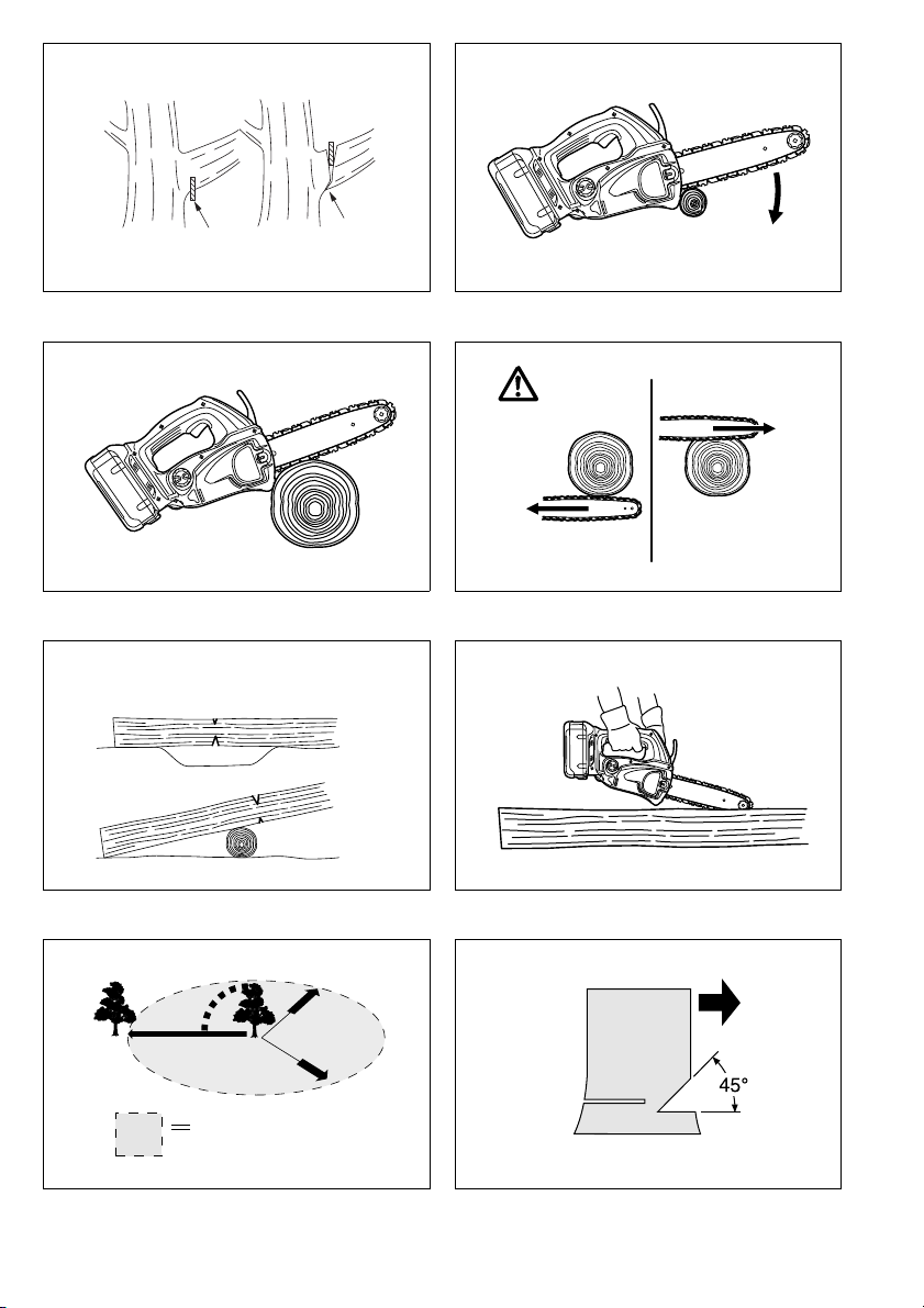
When cutting thick branches, first make a shallow undercut and then make the finish cut from the top. (Fig. 24)
If you try to cut off thick branches from the bottom, the
branch may close in and pinch the saw chain in the cut. If
you try to cut off thick branches from the top without a
shallow undercut, the branch may splinter. (Fig. 25)
If you cannot cut the timber right through with a single
stroke:
Apply light pressure to the handle and continue sawing
and draw the chain saw back a little; then apply the spike
a little lower and finish the cut by raising the handle.
(Fig. 26)
Bucking
For bucking cuts, rest the serrated rail shown in the figure
on the wood to be cut. (Fig. 27)
With the saw chain running, saw into the wood, using the
top handle to raise the saw and the front one to guide it.
Use the serrated rail as a pivot.
Continue the cut by applying slight pressure to the front
handle, easing the saw back slightly. Move the serrated
rail further down the timber and raise the front handle
again.
When making several cuts, switch the chain saw off
between cuts.
CAUTION:
• If the upper edge of the bar is used for cutting, the
chain saw may be deflected in your direction if the
chain becomes trapped. For this reason, cut with the
lower edge, so that the saw will be deflected away from
your body. (Fig. 28)
Cut wood under tension on the pressure side (A) first.
Then make the final cut on the tension side (B). This prevents the bar from becoming trapped. (Fig. 29)
Limbing
CAUTION:
• Limbing may only be performed by trained persons. A
hazard is presented by the risk of kick-back.
When limbing, support the chain saw on the trunk if possible. Do not cut with the tip of the bar, as this presents a
risk of kickback.
Pay particular attention to branches under tension. Do
not cut unsupported branches from below.
Do not stand on the felled trunk when limbing.
Burrowing and parallel-to-grain cuts
CAUTION:
• Burrowing and parallel-to-grain cuts may only be carried out by persons with special training. The possibility
of kickback presents a risk of injury.
Perform parallel-to-grain cuts at as shallow an angle as
possible. Carry out the cut as carefully as possible, as
the serrated rail cannot be used. (Fig. 30)
Felling
CAUTION:
• Felling work may only be performed by trained persons.
The work is hazardous.
Observe local regulations if you wish to fell a tree.
- Before starting felling work, ensure that: (Fig. 31)
(1) Only persons involved in the felling operation are in
the vicinity;
(2) Any person involved has an unhindered path of
retreat through a range of approximately 45° either
side of the felling axis. Consider the additional risk
of tripping over electrical cables;
(3) The base of the trunk is free of foreign objects,
roots and branches;
(4) No persons or objects are present over a distance
of 2 1/2 tree lengths in the direction in which the
tree will fall.
- Consider the following with respect to each tree:
• Direction of lean;
• Loose or dry branches;
• Height of the tree;
• Natural overhang;
• Whether or not the tree is rotten.
- Consider the wind speed and direction. Do not carry
out felling work if the wind is gusting strongly.
- Trimming of root swellings: Begin with the largest swellings. Make the vertical cut first, then the horizontal cut.
(Fig. 32)
- Cut a scarf: The scarf determines the direction in which
the tree will fall, and guides it. It is made on the side
towards which the tree is to fall. Cut the scarf as close
to the ground as possible. First make the horizontal cut
to a depth of 1/5 – 1/3 of the trunk diameter. Do not
make the scarf too large. Then make the diagonal cut.
- Cut any corrections to the scarf across its entire width.
- Make the back cut a little higher than the base cut of
the scarf. The back cut must be exactly horizontal.
Leave approximately 1/10 of the trunk diameter
between the back cut and the scarf.
The wood fibers in the uncut trunk portion act as a
hinge. Do not cut right through the fibers under any circumstances, as the tree will otherwise fall unchecked.
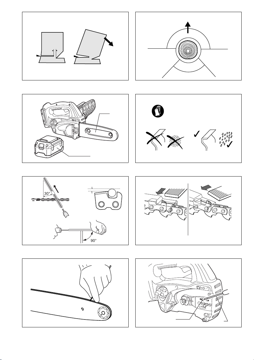
Insert wedges into the back cut in time. (Fig. 33)
- Only plastic or aluminum wedges may be used to keep
the back cut open. The use of iron wedges is prohibited.
- Stand to the side of the falling tree. Keep an area clear
to the rear of the falling tree up to an angle of 45° either
side of the tree axis (refer to the “felling area” figure
(Fig. 31)). Pay attention to falling branches.
- An escape path should be planned and cleared as necessary before cuts are started. The escape path should
extend back and diagonally to the rear of the expected
line of fall as illustrated in figure. (Fig. 34)
21
Page 22

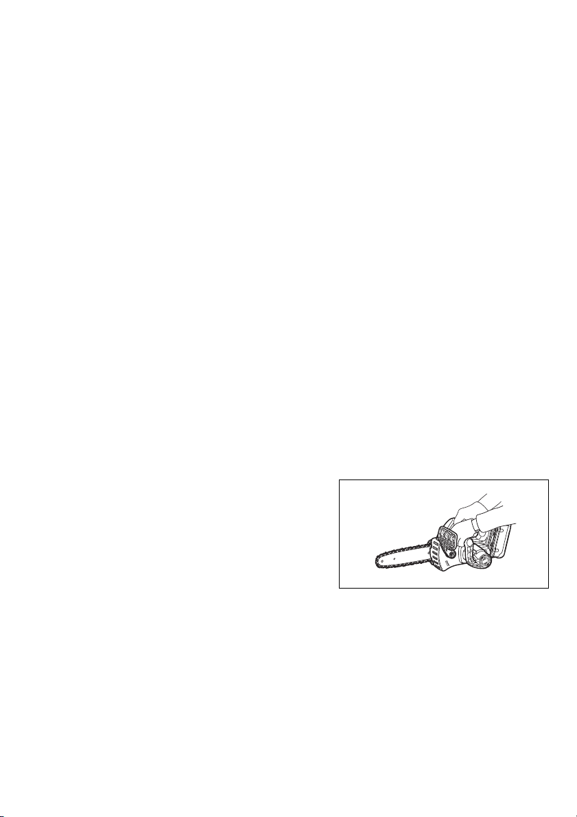
Carrying tool (Fig. 35)
Always remove the battery cartridge from the tool and
overlap the guide bar with the scabbard before carrying
the tool. Also cover the battery cartridge with the battery
cover.
MAINTENANCE
CAUTION:
• Always be sure that the tool is switched off and the battery cartridge is removed before attempting to perform
inspection or maintenance.
• Always wear gloves when performing any inspection or
maintenance.
• Never use gasoline, benzine, thinner, alcohol or the
like. Discoloration, deformation or cracks may result.
Sharpening the saw chain
CAUTION:
• Always remove the battery cartridge and wear safety
gloves when performing work on the saw chain.
Sharpen the saw chain when:
- Mealy sawdust is produced when damp wood is cut;
- The chain penetrates the wood with difficulty, even
when heavy pressure is applied;
- The cutting edge is obviously damaged;
- The saw pulls to the left or right in the wood. The reason for this behaviour is uneven sharpening of the saw
chain, or damage to one side only. (Fig. 36)
Sharpen the saw chain frequently, but remove only a
little material each time.
Two or three strokes with a file are usually sufficient for
routine resharpening. When the saw chain has been
resharpened several times, have it sharpened in a
MAKITA specialist repair shop.
File and file guiding
- Use a special round file (optional accessory) for sharpening.
- Saw chain type 91VG and 91PX: Saw chain round
file, diameter 4.0 mm
- Saw chain type 90SG: Saw chain round file, diameter
4.5 mm
- The file should only engage the material on the forward
stroke. Lift the file off the material on the return stroke.
- Sharpen the shortest cutter first. The length of this cutter is then the gauge dimension for all other cutters on
the saw chain.
- Guide the file as shown in the figure. (Fig. 37)
- The file can be guided more easily if a file holder
(accessory) is employed. The file holder has markings
for the correct sharpening angle of 30° (align the markings parallel to the saw chain) and limits the depth of
penetration (to 4/5 of the file diameter).
Guide the file as shown in the figure. (Fig. 38)
- After sharpening the chain, check the height of the
depth gauge using the chain gauge tool (optional
accessory).
- Remove any projecting material, however small, with a
special flat file (optional accessory).
- Round off the front of the depth gauge again.
- Wash away dust and particles from saw chain after
adjusting the height of depth gauge.
Cleaning guide bar (Fig. 39)
Chips and sawdust will build up in the guide bar groove,
clogging it and impairing oil flow. Always clean out the
chips and sawdust when sharpening or replacing the saw
chain.
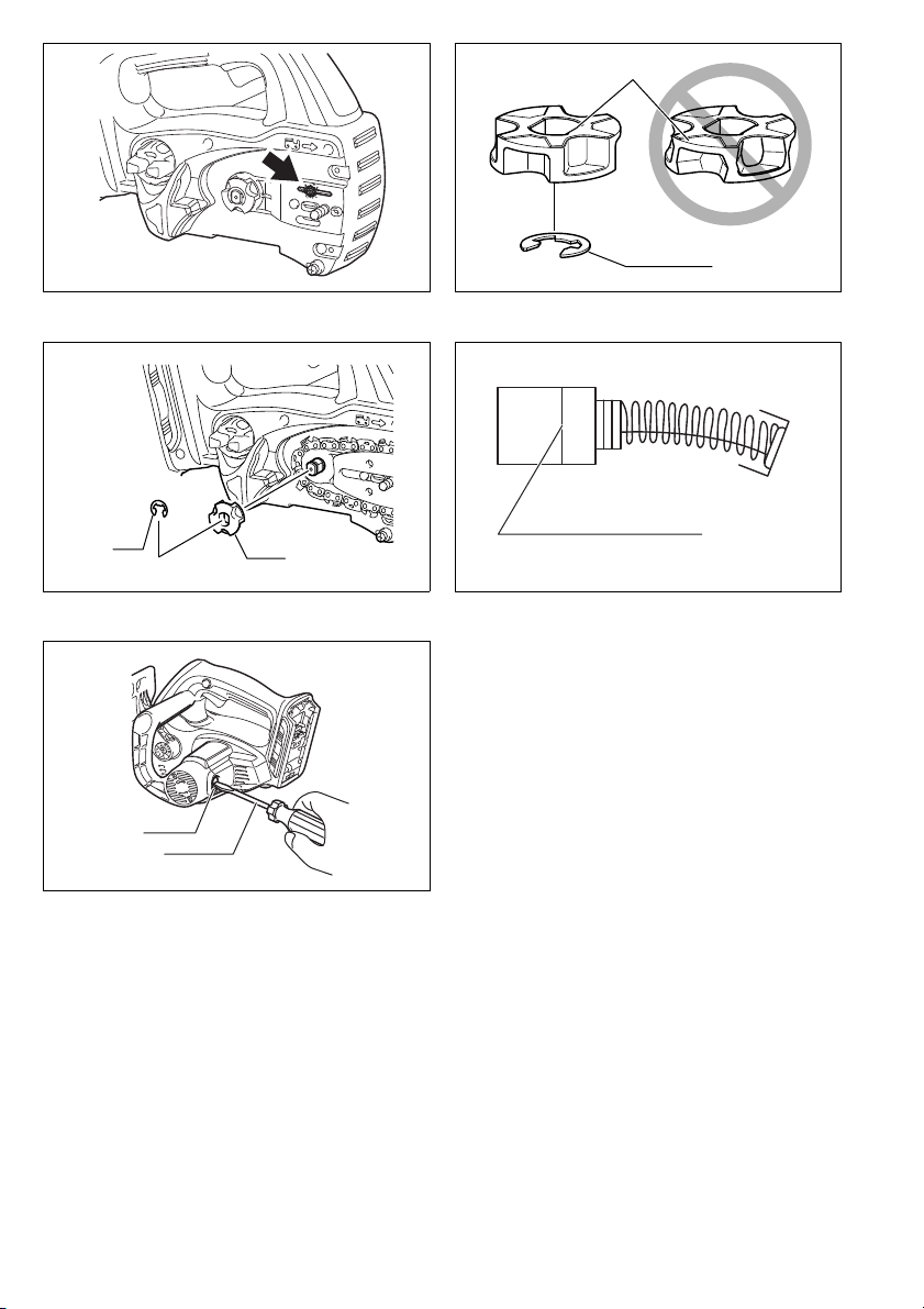
Cleaning the oil discharge hole
Small dust or particles may be built up in the oil discharge hole during operation.
Small dust or particles built up in the oil discharge hole
may impair the oil discharge flow and cause an insufficient lubrication on the whole saw chain.
When a poor chain oil delivery occurs at the top of guide
bar, clean the oil discharge hole as follows.
Remove the battery cartridge from the tool.
Remove the sprocket cover and saw chain from the tool.
(Refer to the section titled “Installing or removing saw
chain”.)
Remove the small dust or particles using a slotted bit
screwdriver with a slender shaft or the like. (Fig. 40)
Insert the battery cartridge into the tool.
Pull the switch trigger to flow built-up dust or particles off
the oil discharge hole by discharging chain oil. (Fig. 41)
Remove the battery cartridge from the tool.
Reinstall the sprocket cover and saw chain on the tool.
Replacing the sprocket (Fig. 42 & 43)
Before fitting a new saw chain, check the condition of the
sprocket.
CAUTION:
• A worn sprocket will damage a new saw chain. Have
the sprocket replaced in this case. The sprocket need
to be installed so that it always faces as shown in the
figure.
Always fit a new locking ring when replacing the
sprocket.
Replacing carbon brushes (Fig. 44 & 45)
Remove and check the carbon brushes regularly.
Replace when they wear down to the limit mark. Keep
the carbon brushes clean and free to slip in the holders.
Both carbon brushes should be replaced at the same
time. Use only identical carbon brushes.
Use a screwdriver to remove the brush holder caps. Take
out the worn carbon brushes, insert the new ones and
secure the brush holder caps.
Storing tool
Clean the tool before storing. Remove any chips and
sawdust from the tool after removing the sprocket cover.
After cleaning the tool, run it under no load to lubricate
the saw chain and guide bar.
Cover the guide bar with the scabbard.
Remove oil from the oil tank to empty it and place the
chain saw.
To maintain product SAFETY and RELIABILITY, repairs,
any other maintenance or adjustment should be performed by Makita Authorized Service Centres, always
using Makita replacement parts.
22
Page 23
OPTIONAL ACCESSORIES
CAUTION:
• These accessories or attachments are recommended
for use with your Makita tool specified in this manual.
The use of any other accessories or attachments might
present a risk of injury to persons. Only use accessory
or attachment for its stated purpose.
If you need any assistance for more details regarding
these accessories, ask your local Makita Service Center.
• Makita genuine battery and charger
• Saw chain
• Scabbard
• Guide bar complete
•File
• Tool bag
• Battery adapter
• Arm cord hook (to be used together with the battery
adapter)
NOTE:
• Some items in the list may be included in the tool package as standard accessories. They may differ from
country to country.
ENG905-1
Noise
The typical A-weighted noise level determined according
to EN60745:
Sound pressure level (L
Sound power level (L
Uncertainty (K): 3.0 dB (A)
Wear ear protection
Vibration
The vibration total value (tri-axial vector sum) determined
according to EN60745:
Model BUC250, UC250D
Work mode: cutting wood
Vibration emission (a
Uncertainty (K): 1.6 m/s
Model BUC300, UC300D
Work mode: cutting wood
Vibration emission (a
Uncertainty (K): 1.5 m/s
• The declared vibration emission value has been measured in accordance with the standard test method and
may be used for comparing one tool with another.
• The declared vibration emission value may also be
used in a preliminary assessment of exposure.
WARNING:
• The vibration emission during actual use of the power
tool can differ from the declared emission value
depending on the ways in which the tool is used.
• Be sure to identify safety measures to protect the operator that are based on an estimation of exposure in the
actual conditions of use (taking account of all parts of
the operating cycle such as the times when the tool is
switched off and when it is running idle in addition to
the trigger time).
): 87.3 dB (A)
pA
): 95.3 dB (A)
WA
): 7.0 m/s
h
2
): 6.3 m/s
h
2
ENG900-1
2
2
ENG901-1
ENH030-4
For European countries only
EC Declaration of Conformity
We Makita Corporation as the responsible manufacturer declare that the following Makita machine(s):
Designation of Machine:
Cordless Chain Saw
Model No./ Type: BUC250, UC250D, BUC300, UC300D
Specifications: see “SPECIFICATIONS” table.
are of series production and
Conforms to the following European Directives:
2000/14/EC, 2006/42/EC
And are manufactured in accordance with the following
standards or standardised documents:
EN60745
The EC-Type Examination Certificate No. 4811008.12010
The EC-Type Examination per 2006/42/EC was performed by:
DEKRA Testing and Certification GmbH
Enderstrasse 92b
01277 Dresden
Germany
Identification No. 2140
The technical documentation is kept by:
Makita International Europe Ltd.
Technical Department,
Michigan Drive, Tongwell,
Milton Keynes, Bucks MK15 8JD, England
The conformity assessment procedure required by Direc-
tive 2000/14/EC was in Accordance with annex V.
Measured Sound Power Level: 95.2 dB (A)
Guaranteed Sound Power Level: 98.0 dB (A)
31.7.2012
Tomoyasu Kato
Director
Makita Corporation
3-11-8, Sumiyoshi-cho,
Anjo, Aichi, 446-8502, JAPAN
23
Page 24

FRANÇAIS (Instructions originales)
Descriptif
1 Indicateur rouge
2 Bouton
3 Batterie
4 Bouton de sécurité
5 Gâchette
6 Protège-main avant
7 Verrouiller
8 Déverrouiller
9 Vis de réglage
10 Mousqueton (point de fixation
de la corde)
11 Témoins
12 Bouton CHECK
13 Faire glisser légèrement
14 Placer à la verticale
15 Enfoncer
16 Desserrer
17 Couvre-pignon
18 Bague de réglage
19 Pignon
SPÉCIFICATIONS
Modèle BUC250 UC250D BUC300 UC300D
Vitesse de chaîne par
minute
Longueur du guide de
chaîne
Type de guide de chaîne
Ty pe
Chaîne
Nombre de dents6969 6 6
Longueur totale 576 mm 589 mm 577 mm 590 mm 626 mm 627 mm
Tension nominale 36 V CC 36 V CC 36 V CC 36 V CC
• Poids, avec la batterie, conformément à la procédure
EPTA-01/2003
Utilisations
L’outil est conçu pour la coupe des branches.
Pas 3/8” 1/4” 3/8” 1/4” 3/8” 3/8”
Nombre de
maillons
d’entraînement
Poids net 4,5 kg 4,5 kg 4,6 kg 4,6 kg
20 Broche de réglage
21 Petit orifice
22 Serrer
23 Levier
24 Bas
25 Haut
26 Guide de chaîne
27 Chaîne
28 Adaptateur
29 Crochet
30 Outil
31 Ceinture
32 Bande du crochet-brassard
33 Support
34 Cordon prolongateur (adapta-
teur de batterie)
35 Adaptateur (adaptateur de bat-
terie)
36 Bouchon du réservoir d’huile
37 Ouverture du réservoir d’huile
8,3 m/s (500 m/min) 8,3 m/s (500 m/min)
250 mm 250 mm 300 mm 300 mm
Guide à
pignon de
renvoi
91VG/
91PX
40 60 40 60 46 46
Barre de
cisellement
25AP
ENE031-2
Guide à
pignon de
renvoi
91VG/
91PX
cisellement
Consignes de sécurité générales pour outils électriques
MISE EN GARDE Veuillez lire toutes les mises en
garde et toutes les instructions. Il y a risque de choc
électrique, d’incendie et/ou de blessure grave si les
mises en garde et les instructions ne sont pas
respectées.
Conservez toutes les mises en garde et instructions
pour référence ultérieure.
38 Fenêtre d’inspection du
réservoir d’huile (pour remplir le
réservoir d’huile)
39 Fenêtre d’inspection du
réservoir d’huile
40 Guide inférieur
41 Zone de chute
42 Sens de la chute
43 Zone de danger
44 Voie de retraite
45 Fourreau (cache de chaîne)
46 Limage vers l’avant
47 1/5 du diamètre de lime
48 Poussières ou particules
49 Tournevis à tête fendue
50 Bague de blocage
51 Trait de limite d’usure
52 Bouchons de porte-charbon
53 Tournevis
8,3 m/s
(500 m/min)
Barre de
25AP 90SG 90SG
Guide à pignon
de renvoi
8,3 m/s
(500 m/min)
Guide à pignon
de renvoi
GEA010-1
24
Page 25
GEB071-6
CONSIGNES DE SÉCURITÉ POUR
TRONÇONNEUSE SANS FIL :
1. Gardez toute partie du corps à l’écart de la
chaîne pendant l’utilisation de la tronçonneuse.
Avant de faire démarrer la tronçonneuse, assurez-vous que la chaîne n’entre en contact avec
rien. Tout moment d’inattention pendant l’utilisation
d’une tronçonneuse comporte un risque de contact
entre la chaîne et vos vêtements ou votre corps.
2. Tenez toujours la tronçonneuse fermement avec
la main droite sur la poignée arrière et la main
gauche sur la poignée avant. N’inversez jamais les
mains pour tenir la tronçonneuse car il y a risque de
blessure.
3. Tenez l’outil électrique uniquement par ses surfaces de poigne isolées, car la chaîne peut entrer
en contact avec des câbles cachés. Le contact de
la chaîne avec un câble sous tension peut mettre les
parties métalliques dénudées de l’outil sous tension
et exposer l’utilisateur à un choc électrique.
4. Portez des lunettes de sécurité et une protection
d’oreilles. Il est recommandé de porter des dispositifs de protection supplémentaires pour la
tête, les mains, les jambes et les pieds. Le port de
vêtements de protection adéquats réduit le risque de
blessure causée par les débris éjectés ou par le
contact avec la chaîne.
5. N’utilisez pas la tronçonneuse en grimpant sur
un arbre. Il y a risque de blessure si la tronçon-
neuse est utilisée sur un arbre.
6. Assurez-vous toujours d’être en bonne position
d’équilibre et d’utiliser la tronçonneuse sur une
surface stable, sûre et plane. Vous risquez de per-
dre l’équilibre ou de perdre la maîtrise de la tronçonneuse si vous travaillez sur une surface glissante ou
instable comme une échelle.
7. Lorsque vous coupez une branche tendue, prenez garde au retour de la branche. Lorsque la ten-
sion exercée sur les fibres de la branche tendue est
libérée, elle risque de frapper l’utilisateur et/ou de
provoquer une perte de maîtrise de la tronçonneuse.
8. Faites preuve d’une grande prudence lorsque
vous coupez des broussailles ou des jeunes
arbres. Des fines pièces de bois, en se coinçant
dans la chaîne, peuvent être projetées vers vous ou
exercer une traction vous mettant hors d’équilibre.
9. Pour transporter la tronçonneuse, coupez le
contact, saisissez-la par la poignée avant et gardez-la éloignée du corps. Avant de transporter
ou de ranger la tronçonneuse, installez toujours
le protecteur du guide de chaîne. Une manipula-
tion adéquate de la tronçonneuse réduit le risque de
contact avec la chaîne en mouvement.
10. Suivez les instructions de lubrification, de
réglage de la tension de la chaîne et de changement des accessoires. Une chaîne mal tendue ou
mal lubrifiée peut se casser ou augmenter les risques de choc en retour.
11. Maintenez les poignées sèches, propres et
exemptes d’huile et de graisse. Les poignées
graisseuses ou huileuses sont glissantes et peuvent
causer une perte de maîtrise.
12. Coupez uniquement dans le bois. N’utilisez pas
la tronçonneuse pour des travaux autres que
ceux pour lesquels elle a été conçue. Par exemple, ne l’utilisez pas pour couper le plastique, les
matériaux de maçonnerie et les matériaux de
construction autres que le bois. L’utilisation de la
tronçonneuse pour effectuer des travaux autres que
ceux pour lesquels elle a été conçue comporte un
risque de danger.
13. Causes de choc en retour et mesures préventives à prendre :
Il y a risque de choc en retour lorsque le nez ou le
bout du guide de chaîne touche un objet, ou lorsque
le bois se referme et coince la chaîne dans sa ligne
de coupe.
Le contact du bout, dans certains cas, peut entraîner une réaction instantanée en sens inverse, projetant le guide de chaîne vers le haut et vers
l’utilisateur.
Le guide de chaîne risque d’être projeté vers l’utilisateur si la chaîne se coince le long de la partie
supérieure du guide de chaîne.
L’une ou l’autre de ces réactions peut entraîner une
perte de maîtrise de la scie et causer une grave
blessure. Ne vous fiez pas uniquement aux dispositifs de sécurité intégrés à la scie. En tant qu’utilisateur de la tronçonneuse, vous devez prendre des
mesures pour écarter les risques d’accident ou de
blessure pendant le travail de coupe.
Le choc en retour est le résultat d’une mauvaise utilisation et/ou de procédures ou conditions inadéquates de travail. Il peut être évité en prenant les
mesures appropriées, tel qu’indiqué ci-dessous :
- Maintenez une prise ferme, avec les pouces et
les doigts encerclant les poignées de la tronçonneuse, tenez la tronçonneuse à deux mains
et placez le corps et les bras dans une position
vous permettant de résister aux chocs en
retour. Les forces de choc en retour peuvent être
contrôlées par l’utilisateur s’il prend les précautions nécessaires. Ne lâchez pas la tronçonneuse.
011443
- Ne vous penchez pas trop en avant, et ne cou-
pez pas plus haut qu’à la hauteur des épaules.
Cela aide à éviter le contact involontaire du bout et
permet de mieux maîtriser la tronçonneuse dans
les situations imprévues.
- Utilisez exclusivement les guides et chaînes
spécifié(e)s par le fabricant. Un remplacement
incorrect du guide ou de la chaîne peut causer le
bris de la chaîne et/ou un choc en retour.
- Suivez les instructions du fabricant concer-
nant l’affûtage et l’entretien de la chaîne. Le risque de choc en retour augmente si l’on abaisse la
jauge de profondeur.
25
Page 26

14. Avant de commencer le travail, assurez-vous que la
tronçonneuse est en bon état et conforme aux réglementations de sécurité. Vérifiez tout particulièrement les points suivants :
• Le frein de chaîne fonctionne bien.
• Le frein de désamorçage fonctionne bien.
• Le guide et le couvre-pignon sont posés correctement.
• La chaîne est bien aiguisée et bien tendue, conformément aux réglementations.
15. Ne faites pas démarrer la tronçonneuse sans
avoir retiré le cache de chaîne. Si vous faites
démarrer la tronçonneuse sans avoir retiré le cache
de chaîne, celui-ci risquera d’être éjecté vers l’avant,
ce qui comporte un risque de blessure et peut
endommager les objets autour de l’utilisateur.
CONSERVEZ CES INSTRUCTIONS.
AVERTISSEMENT :
NE vous laissez PAS tromper (au fil d’une utilisation
répétée) par un sentiment d’aisance et de familiarité
avec le produit, en négligeant le respect rigoureux
des consignes de sécurité qui accompagnent le produit en question. La MAUVAISE UTILISATION de
l’outil ou l’ignorance des consignes de sécurité indiquées dans ce manuel d’instructions peut entraîner
une blessure grave.
ENC007-7
PRÉCAUTIONS IMPORTANTES
POUR LA BATTERIE
1. Avant d’utiliser la batterie, lisez toutes les ins-
tructions et précautions relatives (1) au chargeur
de batterie, (2) à la batterie, et (3) à l’outil utilisant la batterie.
2. Ne démontez pas la batterie.
3. Cessez immédiatement l’utilisation si le temps
de fonctionnement devient excessivement court.
Il y a risque de surchauffe, de brûlures, voire
d’explosion.
4. Si l’électrolyte pénètre dans vos yeux, rincez-les
à l’eau claire et consultez immédiatement un
médecin. Il y a risque de perte de la vue.
5. Ne court-circuitez pas la batterie :
(1) Ne touchez les bornes avec aucun matériau
conducteur.
(2) Évitez de ranger la batterie dans un conte-
neur avec d’autres objets métalliques, par
exemple des clous, des pièces de monnaie,
etc.
(3) N’exposez pas la batterie à l’eau ou à la pluie.
Un court-circuit de la batterie pourrait provoquer
un fort courant, une surchauffe, parfois des brûlures et même une panne.
6. Ne rangez pas l’outil ou la batterie dans des
endroits où la température risque d’atteindre ou
de dépasser 50°C.
7. Ne jetez pas la batterie au feu même si elle est
sérieusement endommagée ou complètement
épuisée. La batterie peut exploser au contact du
feu.
8. Prenez garde d’échapper ou de heurter la batte-
rie.
9. N’utilisez pas une batterie qui a été échappée ou
heurtée.
CONSERVEZ CES INSTRUCTIONS.
Conseils pour assurer la durée de vie optimale de
la batterie
1. Rechargez la batterie avant qu’elle ne soit complètement déchargée.
Arrêtez toujours l’outil et rechargez la batterie
quand vous remarquez que la puissance de
l’outil diminue.
2. Ne rechargez jamais une batterie complètement
chargée. La surcharge réduit la durée de service
de la batterie.
3. Chargez la batterie alors que la température de
la pièce se trouve entre 10°C et 40°C. Avant de
charger une batterie chaude, laissez-la refroidir.
4. Chargez la batterie tous les six mois si elle reste
inutilisée pendant une période prolongée.
DESCRIPTION DU FONCTIONNEMENT
ATTENTION :
• Assurez-vous toujours que l’outil est hors tension et
que sa batterie est retirée avant de l’ajuster ou de vérifier son fonctionnement.
Installation et retrait de la batterie (Fig. 1)
ATTENTION :
• Mettez toujours l’outil hors tension avant de poser ou
de retirer la batterie.
• Lorsque vous posez ou retirez la batterie, tenezfer-
mement l’outil et la batterie.
Si vous ne tenez pas fermement l’outil et la batterie, il s
peuvent vous glisser des mains, et s’abîmer ou vous
blesser.
Pour retirer la batterie, faites-la glisser hors de l’outil tout
en faisant glisser le bouton qui se trouve à l’avant de la
batterie.
Pour poser la batterie, alignez sa languette sur la rainure
à l’intérieur du carter, et faites-la glisser en place. Insérez-la à fond, jusqu’à ce qu’elle se mette en place avec
un léger déclic. Si vous pouvez voir l’indicateur rouge du
côté supérieur du bouton, la batterie n’est pas complètement verrouillée.
ATTENTION :
• Insérez toujours la batterie à fond, jusqu’à ce que l’indi-
cateur rouge ne soit plus visible. Sinon, elle pourrait
tomber accidentellement de l’outil, au risque de vous
blesser ou de blesser quelqu’un se trouvant près de
vous.
• Ne forcez pas pour insérer la batterie. Si elle ne glisse
pas facilement, c’est que vous ne l’insérez pas correctement.
Interrupteur (Fig. 2)
ATTENTION :
• Avant de poser la batterie dans l’outil, assurez-vous
toujours que la gâchette fonctionne bien et retourne en
position d’arrêt lorsque vous la libérez.
Pour éviter tout déclenchement accidentel de la
gâchette, un bouton de sécurité a été prévu.
Pour démarrer l’outil, appuyez sur le bouton de sécurité et
tirez sur la gâchette. Pour l’arrêter, relâchez la gâchette.
26
Page 27
Vérification du frein de chaîne (Fig. 3)
Allumé
Arrêt
Clignotant
E
F
NOTE :
• Si la tronçonneuse ne démarre pas, vous devez libérer
le frein de chaîne. Tirez fermement le protège-main
avant vers l’arrière, jusqu’à ce que vous sentiez qu’il
s’engage.
Tenez la tronçonneuse à deux mains lorsque vous
mettez le contact.
Tenez la poignée supérieure avec la main droite, et la
poignée avant avec la main gauche. Le guide et la
chaîne ne doivent entrer en contact avec aucun objet.
Appuyez d’abord sur le bouton de sécurité, puis sur la
gâchette.
La chaîne démarre immédiatement.
Poussez le protège-main avant vers l’avant avec le dos
de la main. La chaîne doit s’immobiliser immédiatement.
ATTENTION :
• Si la chaîne ne s’arrête pas immédiatement lors de ce
test, la chaîne ne doit être utilisée en aucune
circonstance. Contactez un atelier de réparation
spécialisé en outils MAKITA.
Vérification du frein de désamorçage
Faites démarrer la tronçonneuse.
Libérez complètement la gâchette. La chaîne doit
s’arrêter en moins d’une seconde.
ATTENTION :
• Si la chaîne ne s’arrête pas en moins d’une seconde
lors de ce test, la tronçonneuse ne doit pas être
utilisée. Contactez un atelier de réparation spécialisé
en outils MAKITA.
Réglage de la lubrification de la chaîne (Fig. 4)
Vous pouvez régler le taux d’alimentation de la pompe à
huile à l’aide de la vis de réglage. La quantité d’huile peut
être réglée à l’aide de la clé universelle.
Mousqueton (point de fixation de la corde) (Fig. 5)
Le mousqueton (point de fixation de la corde) sert à
suspendre l’outil. Avant d’utiliser le mousqueton, tirez
dessus pour le dégager et attachez-y une corde.
Circuit de protection de la batterie
Les batteries au lithium-ion sont dotées d’un dispositif de
protection. Ce dispositif coupe automatiquement
l’alimentation de l’outil pour prolonger la durée de service
de la batterie.
Si l’outil et/ou la batterie se trouve dans l’une ou l’autre
des situations suivantes, l’outil cessera automatiquement
de fonctionner.
• Surchargé :
L’outil est utilisé de manière telle qu’il consomme un
courant anormalement élevé.
Il faut alors libérer la gâchette de l’outil et cesser l’application qui cause la surcharge. Tirez ensuite de nouveau sur la gâchette pour redémarrer.
Si l’outil ne démarre pas, cela signifie que la batterie
est trop chaude. Il faut alors laisser refroidir la batterie
avant de tirer de nouveau sur la gâchette.
• Faible tension de la batterie :
La charge restante de la batterie étant trop faible, l’outil
ne fonctionne pas. Il faut alors retirer la batterie et la
recharger.
Témoin de capacité restante de la batterie
(uniquement pour les modèles dotés d’une
batterie BL3622A)
La batterie BL3622A est dotée d’un témoin de capacité
restante. (Fig. 6)
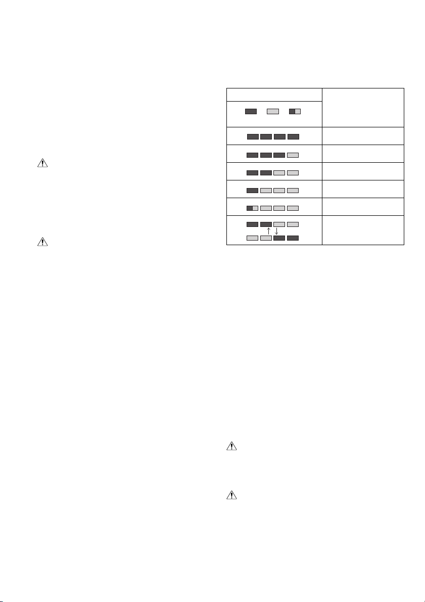
Appuyez sur le bouton CHECK pour afficher la capacité
restante de la batterie. Le témoin s’allume alors pendant
trois secondes environ.
Témoins
Capacité restante
70% à 100%
45 % à 70 %
20% à 45%
0 % à 20 %
Chargez la batterie.
Il y a peut-être un
dysfonctionnement de la
batterie.
011713
• Lorsque seul le témoin le plus bas (à côté de l’“E”)
clignote, ou lorsque aucun des témoins ne s’allume, la
capacité de la batterie est épuisée et l’outil ne peut plus
fonctionner. Le cas échéant, chargez la batterie ou
remplacez-la par une batterie complètement chargée.
• Si au moins deux témoins ne s’allument pas même
après la charge, cela signifie que la batterie a atteint la
fin de sa durée de service.
• Si les deux témoins supérieurs et les deux témoins
inférieurs s’allument alternativement, il se peut que la
batterie ait un dysfonctionnement. Contactez votre
centre de service après-vente agréé Makita.
NOTE :
• Pendant ou juste après l’utilisation de l’outil, la capacité
restante indiquée peut être inférieure au véritable
niveau de capacité.
• Suivant les conditions d’utilisation et la température
ambiante, il se peut que la capacité restante indiquée
par le témoin soit légèrement différente de la charge
réelle.
ASSEMLAGE
ATTENTION :
• Assurez-vous toujours que l’outil est hors tension et
que sa batterie est retirée avant d’effectuer tout travail
dessus.
Installation ou retrait de la chaîne
ATTENTION :
• Assurez-vous toujours que l’outil est hors tension et
que la batterie est retirée avant d’installer ou de retirer
la chaîne de scie.
• Portez toujours des gants pour installer ou retirer la
chaîne de scie.
27
Page 28

1. Pour retirer la tronçonneuse, faites glisser
légèrement le levier dans le sens de la flèche pour
qu’il puisse être libéré de la position de verrouillage,
puis placez-le à la verticale tel qu’illustré. (Fig. 7)
2. Appuyez sur le levier et, tout en le maintenant
enfoncé, tournez-le dans le sens contraire des
aiguilles d’une montre pour desserrer l’écrou jusqu’à
ce que le couvre-pignon se détache. (La pression
sur le levier le fait pénétrer dans l’écrou.) (Fig. 8)
3. Tournez la bague de réglage dans le sens contraire
des aiguilles d’une montre pour réduire la tension de
la chaîne.
4. Retirez le couvre-pignon.
5. Retirez la chaîne et le guide de chaîne de la
tronçonneuse.
6. Pour installer la chaîne, placez une de ses
extrémités sur le dessus du guide de chaîne, et
l’autre extrémité autour du pignon. (Fig. 9)
Posez alors la chaîne tel qu’illustré, car elle tourne dans
le sens de la flèche.
7. Laissez reposer le guide de chaîne dans cette
position sur la tronçonneuse.
8. Tournez la bague de réglage dans le sens contraire
des aiguilles d’une montre pour faire glisser la
broche de réglage dans le sens de la flèche.
(Fig. 10)
9. Placez le couvre-pignon sur la tronçonneuse de
sorte que la broche de réglage se trouve dans un
petit orifice du guide de chaîne. (Fig. 11)
10. Appuyez sur le levier et, tout en le maintenant
enfoncé, tournez-le complètement dans le sens des
aiguilles d’une montre pour serrer l’écrou. Faites-le
ensuite tourner d’un quart de tour dans le sens
contraire des aiguilles d’une montre pour desserrer
légèrement l’écrou. (Fig. 12)
Réglage de la tension de la chaîne
La chaîne peut se détendre au bout de plusieurs heures
d’utilisation. Vérifiez de temps à autre la tension de la
chaîne avant l’utilisation. (Fig. 13)
Redressez le levier.
Enfoncez le levier. Avec le levier enfoncé, faites-le
tourner d’un quart de tour dans le sens contraire des
aiguilles d’une montre pour desserrer légèrement l’écrou.
(La pression sur le levier le fait pénétrer dans l’écrou.)
(Fig. 14)
Tournez la bague de réglage pour ajuster la tension de la
chaîne. Saisissez la chaîne au milieu du guide de chaîne
et soulevez-la. L’espace libre entre le guide de chaîne et
l’éclisse extérieure de la chaîne doit être d’environ
2 à 4 mm. Si l’espace libre n’est pas d’environ 2 à 4 mm,
tournez légèrement la bague de réglage qui retient le
guide de chaîne. Effectuez alors le réglage avec le bout
du guide de chaîne pointant légèrement vers le haut.
(Fig. 15)
Avec le levier enfoncé, tournez-le complètement dans le
sens des aiguilles d’une montre pour serrer l’écrou
fermement. (Fig. 16)
Remettez le levier sur sa position initiale. (Fig. 17)
ATTENTION :
• Si la chaîne est trop tendue, il y a risque de bris de la
chaîne, d’usure du guide de chaîne et de bris de la
bague de réglage.
• L’installation et le retrait de la chaîne doivent être effec-
tués dans un emplacement propre, sans sciure de bois,
etc.
Adaptateur de batterie (en accessoire)
(Fig. 18 et 19)
ATTENTION :
• Avant d’utiliser l’adaptateur de batterie, veuillez lire toutes les instructions de l’outil alimenté par batterie.
• Avant de charger la batterie, retirez-la de l’adaptateur
de batterie. Il ne faut pas charger la batterie pendant
l’utilisation de l’adaptateur de batterie.
Pose ou retrait de l’adaptateur de batterie
• Mettez toujours l’outil hors tension avant d’insérer ou
de retirer l’adaptateur de batterie.
• Pour retirer l’adaptateur de batterie, faites-le glisser
hors de l’outil tout en faisant glisser le bouton sur
l’adaptateur.
• Pour insérer l’adaptateur de batterie, alignez sa languette sur la rainure à l’intérieur du carter et faites-le
glisser en place. Insérez-le à fond jusqu’à ce qu’un
léger déclic se fasse entendre. Si vous pouvez voir
l’indicateur rouge sur la partie supérieure du bouton,
cela indique que l’adaptateur n’est pas complètement
verrouillé en place.
ATTENTION :
• Insérez toujours complètement l’adaptateur de batterie
jusqu’à ce que l’indicateur rouge ne soit plus visible.
Sinon, il pourrait tomber accidentellement de l’outil, au
risque de vous blesser ou de blesser quelqu’un se trouvant près de vous.
• N’insérez pas l’adaptateur pour batterie de force. S’il
ne rentre pas facilement, c’est que vous ne l’insérez
pas correctement.
• Pour retirer la batterie de l’adaptateur ou pour l’y insérer, procédez de la même façon que pour la retirer de
l’outil ou pour l’y insérer.
• Abaissez complètement le crochet lorsque vous accrochez l’adaptateur de batterie à un ceinturon ou à un
objet similaire.
Crochet-brassard (en accessoire) (Fig. 20)
ATTENTION :
• Ne fixez pas le support du crochet-brassard à autre
chose que le cordon prolongateur. Sinon, il y a risque
d’accident ou de blessure.
L’utilisation du crochet-brassard réduit les risques de
sectionnement inattendu du cordon prolongateur lorsque
ce dernier pend librement.
Fixez fermement la bande du crochet-brassard autour de
votre bras, et faites passer le cordon prolongateur à travers le support. La longueur de la bande du crochetbrassard est réglable.
NOTE :
• Ne faites pas passer le cordon prolongateur à travers la
bande.
• Ne forcez pas l’ouverture du support. Sinon, vous risquez de le déformer et de l’abîmer.
OPÉRATION
Lubrification (Fig. 21)
La chaîne se lubrifie automatiquement pendant l’utilisation de l’outil.
Vérifiez la quantité d’huile restante par la fenêtre d’inspection du réservoir d’huile.
Pour remplir le réservoir, retirez le bouchon posé sur
l’ouverture du réservoir d’huile. La capacité du réservoir
d’huile est de 85 ml.
28
Page 29

Une fois le réservoir rempli, n’oubliez pas de visser le
bouchon du réservoir d’huile sur la tronçonneuse.
ATTENTION :
• La première fois que vous faites le plein d’huile sur la
tronçonneuse, ou lorsque vous refaites le plein après
avoir complètement vidé le réservoir d’huile, ajoutez de
l’huile jusqu’au bord inférieur du goulot de remplissage.
Autrement l’alimentation en huile risque d’être affectée.
• Pour huiler la chaîne, utilisez exclusivement de l’huile à
chaîne Makita ou une huile similaire disponible en
magasin.
• N’utilisez jamais d’huile contenant des poussières ou
particules, ni de l’huile volatile.
• Pour élaguer les arbres, utilisez une huile végétale.
L’huile minérale risquerait d’endommager les arbres.
• Ne forcez jamais la tronçonneuse lorsque vous élaguez
des arbres.
• Avant de tronçonner, assurez-vous que le bouchon du
réservoir d’huile est bien vissé en place.
Gardez la tronçonneuse à l’écart de l’arbre. Démarrez-la
et attendez que la chaîne soit bien lubrifiée.
Avant de mettre le contact, mettez le guide inférieur en
contact avec la branche à couper. Le guide de chaîne risque de trembler et vous risquez de vous blesser si vous
procédez à la coupe sans mettre le guide inférieur en
contact avec la branche.
Déplacez simplement la tronçonneuse vers le bas pour
couper la branche. (Fig. 22)
UTILISATION DE LA TRONÇONNEUSE
Un utilisateur sans expérience doit effectuer, en guise
d’entraînement minimum, des coupes de rondins sur un
chevalet ou autre appui.
Elagage des arbres
ATTENTION :
• Eloignez toutes les parties du corps de la chaîne lorsque le moteur fonctionne.
• Tenez la tronçonneuse fermement des deux mains
lorsque le moteur tourne.
• Ne vous penchez pas trop. Gardez une bonne assise
et un bon équilibre en tout temps.
Avant de mettre le contact, mettez le guide inférieur en
contact avec la branche à couper. Le guide de chaîne risque de trembler et vous risquez de vous blesser si vous
procédez à la coupe sans mettre le guide inférieur en
contact avec la branche. (Fig. 23)
Pour couper de grosses branches, commencez par faire
une entaille peu profonde sous la branche, puis terminez
la coupe en procédant par le haut. (Fig. 24)
Si vous essayez de couper les grosses branches par le
bas, la branche risque de s’affaisser et de coincer la
chaîne dans la découpe. Par ailleurs, si vous essayez de
couper les grosses branches à partir du haut sans faire
une légère entaille sous la branche, la branche risque de
se fendre. (Fig. 25)
Si vous n’arrivez pas à couper complètement la branche
d’un seul coup :
Appuyez légèrement sur la poignée et continuez à scier
et déplacez la tronçonneuse d’avant en arrière ; puis dirigez la pointe un peu plus vers le bas et terminez la
coupe en relevant la poignée. (Fig. 26)
Tronçonnage
Pour tronçonner, faites reposer le rail dentelé sur la pièce
de bois à couper, tel qu’illustré. (Fig. 27)
Avec la chaîne qui tourne, sciez dans le bois, en utilisant
la poignée supérieure pour soulever la tronçonneuse, et
la poignée avant pour la diriger.
Utilisez le rail dentelé comme pivot.
Poursuivez la coupe en appliquant une légère pression
sur la poignée avant et en relâchant légèrement la
pression à l’arrière de la tronçonneuse. Abaissez
davantage le rail dentelé sur l’arbre et soulevez encore
une fois la poignée avant.
Lorsque vous effectuez plusieurs coupes, coupez le
contact de la tronçonneuse entre chaque coupe.
ATTENTION :
• Si vous utilisez le bord supérieur du guide pour
tronçonner, la tronçonneuse risquera de dévier dans
votre direction si la chaîne se coince. Il faut donc
tronçonner avec le bord inférieur, de sorte que la
tronçonneuse dévie dans le sens opposé à votre corps.
(Fig. 28)
Si l’arbre est tendu, coupez-le d’abord par la face de
pression (A) illustrée.
Effectuez ensuite la coupe finale par la face de tension
(B) illustrée. Cela permet d’éviter que le guide ne se
coince. (Fig. 29)
Ébranchage
ATTENTION :
• L’ébranchage doit être effectué uniquement par des
personnes qui ont reçu une formation. Il y a risque de
dangereux choc en retour.
Lors de l’ébranchage, appuyez la tronçonneuse contre le
tronc si possible. Ne tronçonnez pas avec le bout du
guide, car il y a risque de choc en retour.
Prêtez une attention particulière aux branches tendues.
Ne tronçonnez pas par en dessous les branches non
soutenues.
Ne montez pas sur l’arbre tombé pour l’ébrancher.
Évidage et coupes dans le sens du grain
ATTENTION :
• L’évidage et les coupes dans le sens du grain doivent
être effectués uniquement par des personnes ayant
reçu une formation spéciale. Il y a risque de choc en
retour et de blessure.
Effectuez les coupes dans le sens du grain avec l’angle
le plus petit possible. Comme il n’est pas possible
d’utiliser le rail dentelé, effectuez la coupe le plus
prudemment possible. (Fig. 30)
Abattage
ATTENTION :
• L’abattage doit être effectué uniquement par des
personnes qui ont reçu une formation. Ce travail est
dangereux.
Respectez les réglementations locales lorsque vous
désirez abattre un arbre.
- Avant de commencer le travail d’abattage, vérifiez les
points suivants : (Fig. 31)
(1) Seules les personnes participant à l’abattage sont
présentes dans la zone de travail ;
(2) Toute personne qui participe à l’abattage doit avoir
une voie de retraite d’environ 45° de chaque côté
de l’axe d’abattage. Tenez aussi compte des
risques de trébuchement sur des câbles
électriques.
29
Page 30

(3) La base du tronc doit être exempte de corps
étrangers, racines et branches.
(4) Il ne doit y avoir personne, ni aucun objet, sur une
distance égale à 2 1/2 fois la longueur de l’arbre
dans le sens où il tombera.
- Pour chaque arbre, tenez compte des facteurs
suivants :
• Le sens de l’abattage ;
• La présence de branches arrachées ou de branches
sèches ;
• La hauteur de l’arbre ;
• La présence d’un surplomb naturel ;
• La pourriture ou non de l’arbre ;
- Tenez compte de la vitesse et de la direction du vent.
N’effectuez pas l’abattage si le vent souffle
violemment.
- Éboutage des pattes de racine : Commencez par les
plus grosses pattes. Effectuez d’abord la coupe
verticale, puis la coupe horizontale. (Fig. 32)
- Faites une entaille : L’entaille détermine le sens dans
lequel l’arbre tombera et elle l’entraîne dans ce sens. Il
faut la faire du côté où l’arbre doit tomber. Entaillez
l’arbre le plus près possible du sol. Coupez d’abord à
l’horizontale sur une profondeur de 1/5 à 1/3 du
diamètre du tronc. Évitez de faire une entaille trop
large. Effectuez ensuite la coupe à la diagonale.
- Les corrections apportées à l’entaille doivent l’être sur
toute sa longueur.
- Faites le trait d’abattage un peu plus haut que la
semelle de l’entaille. Le trait d’abattage doit être
parfaitement horizontal. Laissez environ 1/10 du
diamètre du tronc entre le trait d’abattage et l’entaille.
Les fibres de la partie non coupée du tronc jouent le
rôle de charnière. Ne coupez ces fibres en aucun cas,
car l’arbre tomberait en chute libre. Insérez des
chevilles dans le trait d’abattage au moment opportun.
(Fig. 33)
- Utilisez exclusivement des chevilles de plastique ou
d’aluminium pour garder le trait d’abattage ouvert. Il ne
faut pas utiliser de chevilles de fer.
- Tenez-vous à côté de l’arbre à abattre. Assurez-vous
qu’il y a une aire bien dégagée derrière l’arbre, sur une
plage de 45° de chaque côté par rapport à l’axe
(reportez-vous à la figure “zone d’abattage” (Fig. 31)).
Prenez garde aux chutes de branches.
- Une voie de retraite doit être prévue et nettoyée au
besoin avant de commencer la coupe. La voie de
retraite doit s’étendre derrière et en diagonale derrière
la ligne prévue pour la chute, tel qu’illustré. (Fig. 34)
Transport de l’outil (Fig. 35)
Sortez toujours la batterie de l’outil et recouvrez le guide
de chaîne avec le fourreau avant de transporter l’outil.
Recouvrez également la batterie avec le cache de la batterie.
ENTRETIEN
ATTENTION :
• Assurez-vous toujours que l’outil est hors tension et
que la batterie est retirée avant d’y effectuer tout travail
d’inspection ou d’entretien.
• Portez toujours des gants pour effectuer toute opération d’inspection ou d’entretien.
• N’utilisez jamais d’essence, benzine, diluant, alcool ou
autre produit similaire. Cela risquerait de provoquer la
décoloration, la déformation ou la fissuration de l’outil.
Affûtage de la chaîne
ATTENTION :
• Retirez toujours la batterie et portez des gants de protection lorsque vous travaillez avec la chaîne.
Affûtez la chaîne si :
- de la sciure de bois granuleuse est produite lorsque
vous coupez du bois humide ;
- la chaîne pénètre difficilement dans le bois même si
vous appliquez une forte pression ;
- le tranchant est nettement endommagé ;
- la tronçonneuse tire vers la gauche et la droite dans le
bois. Cela est dû à un affûtage inégal de la chaîne ou
au fait qu’elle est endommagée d’un côté seulement.
(Fig. 36)
Affûtez la chaîne régulièrement, mais en ne retirant
chaque fois qu’une petite quantité de matériau.
Deux ou trois coups de lime suffisent généralement pour
l’affûtage de routine. Après plusieurs affûtages de la
chaîne, faites-la affûter par un centre de réparation agréé
MAKITA.
Lime et limage
- Utilisez une lime ronde spéciale (accessoire en option)
pour l’affûtage.
- Chaîne de type 91VG et 91PX : Lime ronde pour
chaîne d’un diamètre de 4,0 mm
- Chaîne de type 90SG : Lime ronde pour chaîne d’un
diamètre de 4,5 mm
- La lime ne doit toucher le matériau que lors du limage
vers l’avant. Au retour, soulevez la lime pour ne pas
qu’elle touche le matériau.
- Affûtez d’abord le tranchant du maillon le plus court. La
longueur de ce maillon servira de dimension de la
jauge pour tous les autres maillons de la chaîne.
- Passez la lime tel qu’indiqué sur l’illustration. (Fig. 37)
- Le limage sera plus facile si vous employez un portelime (accessoire). Des symboles sont apposés sur le
porte-lime pour indiquer le bon angle d’affûtage de 30°
(alignez les symboles parallèlement à la chaîne) et les
limites de profondeur de pénétration (jusqu’au 4/5 du
diamètre de la lime).
Passez la lime tel qu’indiqué sur l’illustration. (Fig. 38)
- Une fois la chaîne affûtée, vérifiez la hauteur de la
jauge de profondeur à l’aide de l’outil de jauge de la
chaîne (accessoire en option).
- Retirez toute aspérité restante, aussi petite soit-elle, à
l’aide d’une lime plate spéciale (accessoire en option).
- Arrondissez encore une fois l’avant de la jauge de profondeur.
- Essuyez les poussières et particules de la chaîne
après avoir ajusté la hauteur de la jauge de profondeur.
Nettoyage du guide de chaîne (Fig. 39)
Les copeaux et la sciure s’accumulent dans la rainure du
guide de chaîne, ce qui la colmate et entrave la bonne
répartition de l’huile. Enlevez toujours les copeaux et la
sciure lorsque vous affûtez ou que vous remplacez la
chaîne de scie.
30
Page 31

Nettoyage de l’orifice d’évacuation en huile
Des poussières ou particules peuvent s’accumuler dans
l’orifice d’évacuation en huile pendant l’utilisation.
Les poussières ou particules accumulées dans l’orifice
d’évacuation en huile peuvent affecter l’évacuation en
huile et causer une lubrification insuffisante de la chaîne.
Lorsque l’évacuation en huile ne s’effectue pas correctement sur la partie supérieure du guide de chaîne, nettoyez l’orifice d’évacuation en huile en procédant comme
suit.
Retirez la batterie de l’outil.
Retirez le couvre-pignon et la chaîne de l’outil. (Reportez-vous à la section intitulée “Installation ou retrait de la
chaîne”.)
Retirez les poussières ou particules à l’aide d’un tournevis à tête fendue et à tige mince, ou d’un objet similaire.
(Fig. 40)
Insérez la batterie dans l’outil.
Appuyez sur la gâchette pour que les poussières et particules accumulées dans l’orifice d’alimentation en huile
soient évacuées par l’alimentation en huile. (Fig. 41)
Retirez la batterie de l’outil.
Remettez en place le couvre-pignon et la chaîne sur
l’outil.
Remplacement du pignon (Fig. 42 et 43)
Avant de poser une chaîne neuve, vérifiez l’état du
pignon.
ATTENTION :
• La chaîne neuve sera endommagée si le pignon est
usé. Le cas échéant, faites remplacer le pignon. Le
pignon doit être installé de sorte qu’il soit toujours
orienté comme indiqué sur l’illustration.
Posez toujours une bague de blocage neuve lorsque
vous remplacez le pignon.
Remplacement des charbons (Fig. 44 et 45)
Retirez et vérifiez régulièrement les charbons. Remplacez-les lorsqu’ils sont usés jusqu’au trait de limite
d’usure. Maintenez les charbons propres et en état de
glisser aisément dans les porte-charbon. Les deux charbons doivent être remplacés en même temps. N’utilisez
que des charbons identiques.
Utilisez un tournevis pour retirer les bouchons de portecharbon. Enlevez les charbons usés, insérez-en de nouveaux et revissez solidement les bouchons de portecharbon.
Rangement de l’outil
Nettoyez l’outil avant de le ranger. Essuyez les copeaux
et la sciure de bois qui recouvrent l’outil après avoir retiré
le couvre-pignon. Après avoir nettoyé l’outil, faites le tourner à vide pour lubrifier la chaîne et le guide de chaîne.
Recouvrez le guide de chaîne avec le fourreau.
Videz le réservoir d’huile et posez la tronçonneuse.
Pour maintenir la SÉCURITÉ et la FIABILITÉ du produit,
les réparations et tout autre travail d’entretien ou de
réglage doivent être effectués dans un centre de service
après-vente Makita agréé, exclusivement avec des pièces de rechange Makita.
ACCESSOIRES EN OPTION
ATTENTION :
• Ces accessoires ou pièces complémentaires sont
recommandés pour l’utilisation avec l’outil Makita spécifié dans ce mode d’emploi. L’utilisation de tout autre
accessoire ou pièce complémentaire peut comporter
un risque de blessure. N’utilisez les accessoires ou pièces qu’aux fins auxquelles ils ont été conçus.
Si vous désirez obtenir plus de détails concernant ces
accessoires, veuillez contacter le centre de service
après-vente Makita le plus près.
• Batterie et chargeur Makita authentiques
•Chaîne
• Fourreau
• Guide de chaîne complet
•Lime
• Sac de l’outil
• Adaptateur de batterie
• Crochet-brassard (à utiliser avec l’adaptateur de
batterie)
NOTE :
• Il se peut que certains éléments de la liste soient
compris dans l’emballage de l’outil en tant
qu’accessoires standard. Ils peuvent varier d’un pays à
l’autre.
ENG905-1
Bruit
Niveau de bruit pondéré A typique, déterminé selon
EN60745 :
Niveau de pression sonore (L
Niveau de puissance sonore (L
Incertitude (K) : 3,0 dB (A)
Porter des protecteurs anti-bruit
) : 87,3 dB (A)
pA
) : 95,3 dB (A)
WA
ENG900-1
Vibrations
Valeur totale de vibrations (somme de vecteur triaxial)
déterminée selon EN60745 :
Modèle BUC250, UC250D
Mode de travail : coupe du bois
Émission de vibrations (a
Incertitude (K) : 1,6 m/s
Modèle BUC300, UC300D
Mode de travail : coupe du bois
Émission de vibrations (a
Incertitude (K) : 1,5 m/s
) : 7,0 m/s2
h
2
) : 6,3 m/s2
h
2
31
Page 32

• La valeur d’émission de vibrations déclarée a été
mesurée conformément à la méthode de test standard
et peut être utilisée pour comparer les outils entre eux.
• La valeur d’émission de vibrations déclarée peut aussi
être utilisée pour l’évaluation préliminaire de l’exposition.
ENG901-1
AVERTISSEMENT :
• L’émission de vibrations lors de l’usage réel de l’outil
électrique peut être différente de la valeur d’émission
déclarée, suivant la façon dont l’outil est utilisé.
• Les mesures de sécurité à prendre pour protéger l’utilisateur doivent être basées sur une estimation de
l’exposition dans des conditions réelles d’utilisation (en
tenant compte de toutes les composantes du cycle
d’utilisation, comme par exemple le moment de sa mise
hors tension, lorsqu’il tourne à vide et le moment de
son déclenchement).
ENH030-4
Pour les pays d’Europe uniquement
Déclaration de conformité CE
Makita Corporation, en tant que fabricant responsable, déclare que la ou les machines suivantes :
Désignation de la machine :
Tronçonneuse sans Fil
N° de modèle / Type : BUC250, UC250D, BUC300,
UC300D
Spécifications : voir le tableau “SPÉCIFICATIONS”.
sont produites en série et
sont conformes aux Directives européennes suivantes :
2000/14/CE, 2006/42/CE
et qu’elles sont fabriquées conformément aux normes ou
documents normalisés suivants :
EN60745
N° certifié de l’examen de type CE 4811008.12010
L’examen de type CE pour 2006/42/CE a été effectué
par :
DEKRA Testing and Certification GmbH
Enderstrasse 92b
01277 Dresden
Allemagne
N° d’identification 2140
La documentation technique est conservée par :
Makita International Europe Ltd.
Service technique,
Michigan Drive, Tongwell,
Milton Keynes, Bucks MK15 8JD, Angleterre
La procédure d’évaluation de la conformité requise par la
Directive 2000/14/CE a été réalisée conformément à
l’Annexe V.
Niveau de puissance sonore mesuré : 95,2 dB (A)
Niveau de puissance sonore garanti : 98,0 dB (A)
31.7.2012
32
Tomoyasu Kato
Directeur
Makita Corporation
3-11-8, Sumiyoshi-cho,
Anjo, Aichi, 446-8502, JAPAN
Page 33

DEUTSCH (Originale Anleitungen)
Übersicht
1 Rote Anzeige
2 Knopf
3Akku
4 Einschaltarretierung
5 EIN-/AUS-Schalter
6 Vorderer Handschutz
7 Verriegeln
8 Entriegeln
9 Einstellschraube
10 Karabiner
(Seilbefestigungspunkt)
11 Anzeigelampen
12 Taste CHECK
13 Geringfügig verschieben
14 In Aufrechtstellung bringen
15 Hineindrücken
16 Lösen
17 Kettenraddeckel
18 Stellrad
19 Kettenrad
TECHNISCHE DATEN
Modell BUC250 UC250D BUC300 UC300D
Kettendrehzahl 8,3 m/s (500 m/min) 8,3 m/s (500 m/min)
Schwertlänge 250 mm 250 mm 300 mm 300 mm
Schwerttyp
Typ 91VG/91PX 25AP 91VG/91PX 25AP 90SG 90SG
Sägekette
Nennspannung DC 36 V DC 36 V DC 36 V DC 36 V
• Gewicht mit Akku nach EPTA-Verfahren 01/2003
Vorgesehene Verwendung
Die Maschine ist für das Schneiden von Ästen vorgesehen.
Allgemeine Sicherheitswarnungen für
Elektrowerkzeuge
WARNUNG Lesen Sie alle Sicherheitswarnungen
und Anweisungen durch. Eine Missachtung der unten
aufgeführten Warnungen und Anweisungen kann zu
einem elektrischen Schlag, Brand und/oder schweren
Verletzungen führen.
Bewahren Sie alle Warnungen und Anweisungen für
spätere Bezugnahme auf.
Teilung 3/8” 1/4” 3/8” 1/4” 3/8” 3/8”
Treibsglieder 40 60 40 60 46 46
Zähnezahl 6 9 6 9 6 6
Gesamtlänge 576 mm 589 mm 577 mm 590 mm 626 mm 627 mm
Nettogewicht 4,5 kg 4,5 kg 4,6 kg 4,6 kg
20 Einstellstift
21 Kleines Loch
22 Anziehen
23 Hebel
24 Niedrig
25 Hoch
26 Schwert
27 Sägekette
28 Adapter
29 Haken
30 Maschine
31 Gürtel
32 Armkabelhakenband
33 Halter
34 Verlängerungskabel
(Akkuadapter)
35 Adapter (Akkuadapter)
36 Öltankverschluss
37 Öltanköffnung
Umlenk-
stern-
schwert
Schnitzschwert
ENE031-2
GEA010-1
38 Ölstand-Prüffenster (zum
Auffüllen des Tanks mit Öl)
39 Ölstand-Prüffenster
40 Untere Führung
41 Fällbereich
42 Fällrichtung
43 Gefahrenzone
44 Fluchtweg
45 Sägekettenschutz
(Kettenabdeckung)
46 Vorwärtshub der Feile
47 1/5 des Feilendurchmessers
48 Kleine Staubkörner oder
Partikel
49 Schlitzschraubenzieher
50 Sicherungsring
51 Verschleißgrenze
52 Bürstenhalterkappe
53 Schraubendreher
8,3 m/s
(500 m/min)
Umlenk-
stern-
schwert
Schnitzschwert
Umlenk-
stern-
schwert
SICHERHEITSWARNUNGEN FÜR
AKKU-KETTENSÄGE
1. Halten Sie alle Körperteile während des Betriebs
der Kettensäge von der Sägekette fern. Vergewissern Sie sich vor dem Einschalten der Kettensäge, dass die Sägekette nicht mit irgendeinem
Gegenstand in Berührung ist.
Unaufmerksamkeit während des Betriebs von Kettensägen kann dazu führen, dass Ihre Kleidung oder
Körperteile von der Sägekette erfasst werden.
2. Halten Sie die Kettensäge stets mit Ihrer rechten
Hand am hinteren Griff und mit Ihrer linken Hand
am vorderen Griff. Das Halten der Kettensäge mit
vertauschter Handhaltung führt zu erhöhter Verletzungsgefahr und ist daher unbedingt zu vermeiden.
8,3 m/s
(500 m/min)
Umlenk-
stern-
schwert
GEB071-6
Ein Augenblick der
33
Page 34

3. Das Elektrowerkzeug darf nur an den isolierten
Griffflächen gehalten werden, well die Sägekette
verdeckte Leitungen berühren kann. Sägeketten,
die einen spannungsführenden Draht berühren,
machen metallene Teile des Elektrowerkzeugs
spannungsführend und könnten dem Bediener
einen elektrischen Schlag versetzen.
4. Tragen Sie eine Schutzbrille und einen Gehörschutz. Zusätzliche Schutzausrüstung für Kopf,
Hände, Beine und Füße wird empfohlen. Geeig-
nete Schutzkleidung reduziert die Verletzungsgefahr
durch fliegende Trümmer oder versehentlichen Kontakt mit der Sägekette.
5. Betreiben Sie die Kettensäge nicht in einem
Baum. Der Betrieb der Kettensäge in einer Baum-
krone kann zu Verletzungen führen.
6. Achten Sie stets auf sicheren Stand, und betreiben Sie die Kettensäge nur, wenn Sie auf einer
festen, sicheren und ebenen Fläche stehen.
Schlüpfrige oder instabile Standflächen, wie z. B.
Leitern, können zu einem Verlust der Balance oder
der Kontrolle über die Kettensäge führen.
7. Wenn Sie einen unter Spannung stehenden Ast
abschneiden, achten Sie auf Zurückschnellen.
Wenn sich die Spannung in den Holzfasern entlädt,
kann der unter Spannung stehende Ast die Bedienungsperson treffen und/oder die Kettensäge außer
Kontrolle bringen.
8. Lassen Sie beim Schneiden von Gestrüpp und
jungen Bäumen äußerste Vorsicht walten. Die
dünnen Äste können an der Sägekette hängen bleiben und gegen Sie geschleudert werden oder Sie
aus dem Gleichgewicht bringen.
9. Tragen Sie die Kettensäge nach dem Ausschalten
mit Abstand zu Ihrem Körper am vorderen Griff.
Bringen Sie zum Transportieren oder Lagern der
Kettensäge stets die Schwertschutzhülle an.
Sachgemäße Handhabung der Kettensäge reduziert
die Wahrscheinlichkeit einer versehentlichen Berührung der umlaufenden Sägekette.
10. Befolgen Sie die Anweisungen für die Schmierung, die Kettenspannung und den Austausch
von Zubehör. Eine unsachgemäß gespannte oder
geschmierte Kette kann entweder reißen oder die
Gefahr von Rückschlägen erhöhen.
11. Halten Sie die Griffe trocken, sauber und frei von
Öl und Fett.
schlüpfrig und verursachen den Verlust der Kontrolle.
12. Schneiden Sie nur Holz. Verwenden Sie die Kettensäge nicht für sachfremde Zwecke. Zum Beispiel: Verwenden Sie die Kettensäge nicht zum
Schneiden von Kunststoff, Mauerwerk oder
Nicht-Holz-Baumaterial. Der Gebrauch der Ketten-
säge für sachfremde Zwecke kann zu einer Gefahrensituation führen.
Fett- und ölverschmierte Griffe sind
13. Ursachen und Verhütung von Rückschlägen:
Rückschläge können auftreten, wenn die Nase oder
Spitze des Schwerts ein Objekt berührt, oder wenn
sich das Holz schließt und die Sägekette im Schnitt
einklemmt.
Spitzenkontakt kann in manchen Fällen eine plötzliche Gegenreaktion verursachen, so dass das
Schwert nach oben oder hinten zur Bedienungsperson geschleudert wird.
Durch Einklemmen der Sägekette entlang dem oberen Lauf des Schwerts kann das Schwert zur Bedienungsperson zurückgeschleudert werden.
Jede dieser Reaktionen kann zu einem Verlust der
Kontrolle über die Säge und daraus resultierenden
schweren Verletzungen führen. Verlassen Sie sich
nicht ausschließlich auf die in Ihre Säge eingebauten
Sicherheitsvorrichtungen. Als Kettensägenbenutzer
sollten Sie bestimmte Maßnahmen ergreifen, um Ihre
Sägearbeiten unfall- und verletzungsfrei zu halten.
Rückschlag ist das Resultat falscher Handhabung der
Maschine und/oder falscher Arbeitsverfahren oder bedingungen und kann durch Anwendung der nachstehenden Vorsichtsmaßnahmen vermieden werden:
- Halten Sie die Kettensäge beidhändig mit
festem Griff, wobei Ihre Daumen und Finger die
Griffe umschließen, und positionieren Sie Körper und Arme so, dass Sie Rückschlagkräfte
auffangen können. Rückschlagkräfte können
durch Treffen geeigneter Vorsichtsmaßnahmen
von der Bedienungsperson kontrolliert werden.
Lassen Sie die Kettensäge nicht los.
011443
- Übernehmen Sie sich nicht, und schneiden Sie
nicht oberhalb der Schulterhöhe. Dies trägt zur
Verhütung unbeabsichtigten Spitzenkontakts bei
und ermöglicht bessere Kontrolle der Kettensäge
in unerwarteten Situationen.
- Verwenden Sie nur vom Hersteller empfohlene
Schwerter und Ketten. Ungeeignete Schwerter
und Ketten können Kettenbruch und/oder Rückschlag verursachen.
- Befolgen Sie die Herstelleranweisungen zum
Schärfen und Warten der Sägekette. Eine Verringerung der Tiefenanschlaghöhe kann zu vermehrten Rückschlägen führen.
14. Stellen Sie vor Arbeitsbeginn sicher, dass die Ket-
tensäge in einwandfreiem Betriebszustand ist, und
dass ihr Zustand den Sicherheitsvorschriften entspricht. Prüfen Sie insbesondere, dass:
• Die Kettenbremse einwandfrei funktioniert;
• Die Auslaufbremse einwandfrei funktioniert;
• Schwert und Kettenraddeckel korrekt angebracht
sind;
• Die Kette geschärft und vorschriftsmäßig gespannt
worden ist;
34
Page 35

15. Schalten Sie die Kettensäge nicht mit noch
angebrachtem Kettenschutz ein. Wird die Ketten-
säge mit noch angebrachtem Kettenschutz eingeschaltet, kann der Kettenschutz nach vorn
herausgeschleudert werden, was zu Personenverletzungen und Beschädigung von Gegenständen im
Umfeld des Bedieners führen kann.
BEWAHREN SIE DIESE HINWEISE
SORGFÄLTIG AUF.
WARNUNG:
Lassen Sie sich NICHT durch Bequemlichkeit oder
Vertrautheit mit dem Produkt (durch wiederholten
Gebrauch erworben) von der strikten Einhaltung der
Sicherheitsregeln für das vorliegende Produkt abhalten. MISSBRAUCH oder Missachtung der Sicherheitsvorschriften in dieser Anleitung können
schwere Verletzungen verursachen.
ENC007-7
WICHTIGE SICHERHEITSVORSCHRIFTEN
FÜR AKKU
1. Lesen Sie vor der Benutzung des Akkus alle
Anweisungen und Warnhinweise, die an (1)
Ladegerät, (2) Akku und (3) Akkuwerkzeug angebracht sind.
2. Unterlassen Sie ein Zerlegen des Akkus.
3. Falls die Betriebszeit beträchtlich kürzer gewor-
den ist, stellen Sie den Betrieb sofort ein. Anderenfalls besteht die Gefahr von Überhitzung,
möglichen Verbrennungen und sogar einer
Explosion.
4. Falls Elektrolyt in Ihre Augen gelangt, waschen
Sie sie mit sauberem Wasser aus, und begeben
Sie sich unverzüglich in ärztliche Behandlung.
Anderenfalls können Sie Ihre Sehkraft verlieren.
5. Der Akku darf nicht kurzgeschlossen werden:
(1) Die Kontakte dürfen nicht mit leitfähigem
Material berührt werden.
(2) Lagern Sie den Akku nicht in einem Behälter
zusammen mit anderen Metallgegenständen,
wie z.B. Nägel, Münzen usw.
(3) Setzen Sie den Akku weder Wasser noch
Regen aus.
Ein Kurzschluss des Akkus verursacht starken
Stromfluss, der Überhitzung, Verbrennungen
und einen Defekt zur Folge haben kann.
6. Lagern Sie Maschine und Akku nicht an Orten,
an denen die Temperatur 50°C erreichen oder
überschreiten kann.
7. Versuchen Sie niemals, den Akku zu verbrennen,
selbst wenn er stark beschädigt oder vollkommen verbraucht ist. Der Akku kann im Feuer
explodieren.
8. Achten Sie darauf, dass der Akku nicht fallen
gelassen oder Stößen ausgesetzt wird.
9. Verwenden Sie keinen Akku, der fallen gelassen
oder erschüttert wurde.
BEWAHREN SIE DIESE HINWEISE
SORGFÄLTIG AUF.
Hinweise zur Aufrechterhaltung der maximalen
Akku-Nutzungsdauer
1. Laden Sie den Akku, bevor er vollkommen
erschöpft ist.
Schalten Sie die Maschine stets aus, und laden
Sie den Akku, wenn Sie ein Nachlassen der
Maschinenleistung feststellen.
2. Unterlassen Sie das erneute Laden eines voll
aufgeladenen Akkus. Überladen führt zu einer
Verkürzung der Nutzungsdauer des Akkus.
3. Laden Sie den Akku bei Raumtemperatur zwischen 10°C – 40°C. Lassen Sie einen heißen
Akku abkühlen, bevor Sie ihn laden.
4. Laden Sie den Akku bei längerer Nichtbenutzung
alle sechs Monate nach.
FUNKTIONSBESCHREIBUNG
VORSICHT:
• Vergewissern Sie sich vor der Durchführung von Ein-
stellungen oder Funktionsprüfungen der Maschine
stets, dass die Maschine ausgeschaltet und der Akku
abgenommen ist.
Ein- und Ausbau des Akkus (Abb. 1)
VORSICHT:
• Schalten Sie stets die Maschine aus, bevor Sie den
Akku anbringen oder abnehmen.
• Halten Sie Maschine und Akku beim Anbringen
oder Abnehmen des Akkus sicher fest.
Wenn Sie Maschine und Akku nicht sicher festhalten,
können sie Ihnen aus der Hand rutschen, was zu einer
Beschädigung der Maschine und des Akkus und zu
Körperverletzungen führen kann.
Ziehen Sie den Akku zum Abnehmen von der Maschine
ab, während Sie den Knopf an der Vorderseite des Akkus
verschieben.
Richten Sie zum Anbringen des Akkus dessen Führungsfeder auf die Nut im Gehäuse aus, und schieben
Sie den Akku hinein. Schieben Sie ihn vollständig ein, bis
er mit einem hörbaren Klicken einrastet. Falls die rote
Anzeige an der Oberseite des Knopfes sichtbar ist, ist
der Akku-Adapter nicht vollständig verriegelt.
VORSICHT:
• Schieben Sie den Akku stets bis zum Anschlag ein, bis
die rote Anzeige nicht mehr sichtbar ist. Anderenfalls
kann er aus der Maschine herausfallen und Sie oder
umstehende Personen verletzen.
• Unterlassen Sie Gewaltanwendung beim Anbringen
des Akkus. Falls der Akku nicht reibungslos hineingleitet, ist er nicht richtig ausgerichtet.
Schalterbetätigung (Abb. 2)
VORSICHT:
• Vergewissern Sie sich vor dem Einsetzen des Akkus in
die Maschine stets, dass der EIN-/AUS-Schalter ordnungsgemäß funktioniert und beim Loslassen in die
AUS-Stellung zurückkehrt.
Um eine versehentliche Schalterbetätigung zu verhindern, ist die Maschine mit einer Schalterarretierung ausgestattet.
Zum Einschalten drücken Sie den EIN-/AUS-Schalter
und gleichzeitig die Schalterarretierung. Zum Ausschalten den EIN-/AUS-Schalter loslassen.
35
Page 36

Überprüfen der Kettenbremse (Abb. 3)
Ein
Aus
Blinkt
HINWEIS:
• Falls die Kettensäge nicht anläuft, muss die
Kettenbremse gelöst werden. Ziehen Sie den vorderen
Handschutz kräftig zurück, bis Einrasten spürbar ist.
Halten Sie die Kettensäge beim Einschalten mit beiden
Händen.
Halten Sie den Obergriff mit der rechten, und den
Frontgriff mit der linken Hand. Dabei dürfen Schwert und
Kette mit keinem Gegenstand in Berührung sein.
Drücken Sie zuerst die Einschaltarretierung, dann den
EIN-/AUS-Schalter.
Die Sägekette läuft sofort an.
Schieben Sie den vorderen Handschutz mit dem Handrücken vorwärts. Die Sägekette muss zum sofortigen
Stillstand kommen.
VORS ICHT:
• Sollte die Sägekette bei der Durchführung dieser
Prüfung nicht sofort anhalten, darf die Säge unter
keinen Umständen benutzt werden. Konsultieren Sie
eine MAKITA-Reparaturwerkstatt.
Überprüfen der Auslaufbremse
Schalten Sie die Kettensäge ein.
Lassen Sie den EIN-/AUS-Schalter vollkommen los. Die
Sägekette muss innerhalb einer Sekunde zum Stillstand
kommen.
VORS ICHT:
• Sollte die Sägekette bei der Durchführung dieser
Prüfung nicht innerhalb einer Sekunde zum Stillstand
kommen, darf die Säge nicht benutzt werden.
Konsultieren Sie eine MAKITA-Reparaturwerkstatt.
Einstellen der Kettenschmierung (Abb. 4)
Die Ölpumpen-Fördermenge kann mit der Einstellschraube reguliert werden. Verwenden Sie zur Einstellung der Ölmenge den Kombischlüssel.
Karabiner (Seilbefestigungspunkt) (Abb. 5)
Der Karabiner (Seilbefestigungspunkt) dient zum Aufhängen der Maschine. Den Karabiner vor der Benutzung
herausziehen und ein Seil daran anbinden.
Akku-Schutzsystem
Lithium-Ionen-Akkus sind mit einem Schutzsystem ausgestattet. Dieses System schaltet die Stromversorgung
der Maschine automatisch ab, um die Akku-Lebensdauer
zu verlängern.
Die Maschine schaltet sich während des Betriebs automatisch ab, wenn Maschine und/oder Akku einer der folgenden Bedingungen unterliegen:
• Überlastung:
Die Maschine wird auf eine Weise benutzt, die eine
ungewöhnlich hohe Stromaufnahme bewirkt.
Lassen Sie in dieser Situation den Ein-Aus-Schalter
der Maschine los, und brechen Sie die Arbeit ab, die
eine Überlastung der Maschine verursacht hat. Betätigen Sie dann den Ein-Aus-Schalter erneut, um die
Maschine wieder zu starten.
Falls die Maschine nicht startet, ist der Akku überhitzt.
Lassen Sie den Akku in dieser Situation abkühlen,
bevor Sie den Ein-Aus-Schalter erneut betätigen.
• Niedrige Akkuspannung:
Die Akku-Restkapazität ist zu niedrig, und die
Maschine funktioniert nicht. Nehmen Sie in dieser
Situation den Akku ab, und laden Sie ihn auf.
Akku-Restkapazitätsanzeige (nur für Modelle mit
Akku BL3622A)
Der Akku BL3622A ist mit einer AkkuRestkapazitätsanzeige ausgestattet. (Abb. 6)
Drücken Sie die Taste CHECK, um die AkkuRestkapazität anzuzeigen. Daraufhin leuchten die
Anzeigelampen etwa drei Sekunden lang.
Anzeigelampen
Restkapazität
E
011713
• Wenn nur die unterste Anzeigelampe (neben “E”) blinkt
oder keine der Anzeigelampen leuchtet, ist die
Akkukapazität aufgebraucht, so dass das
Akkuwerkzeug nicht funktioniert. Laden Sie in diesen
Fällen den Akku auf, oder tauschen Sie den leeren
Akku gegen einen voll aufgeladenen aus.
• Wenn zwei oder mehr Anzeigelampen nach Abschluss
des Ladevorgangs nicht leuchten, hat der Akku das
Ende seiner Nutzungsdauer erreicht.
• Wenn die oberen und unteren zwei Anzeigelampen
abwechselnd leuchten, liegt möglicherweise eine
Funktionsstörung im Akku vor. Kontaktieren Sie Ihre
örtliche autorisierte Makita-Kundendienststelle.
HINWEIS:
• Während des Gebrauchs oder unmittelbar nach der
Benutzung des Akkuwerkzeugs kann die angezeigte
Kapazität niedriger als das tatsächliche Ladeniveau
sein.
• Abhängig von den Benutzungsbedingungen und der
Umgebungstemperatur kann die Anzeige geringfügig
von der tatsächlichen Kapazität abweichen.
F
70 bis 100%
45 bis 70%
20 bis 45%
0 bis 20%
Den Akku aufladen.
Möglicherweise liegt
eine Funktionsstörung
im Akku vor.
MONTAGE
VORSICHT:
• Vergewissern Sie sich vor der Ausführung von Arbeiten
an der Maschine stets, dass die Maschine ausgeschaltet und der Akku abgenommen ist.
Montage bzw. Demontage der Sägekette
VORSICHT:
• Vergewissern Sie sich vor der Montage bzw. Demontage der Sägekette stets, dass die Maschine ausgeschaltet und der Akku entfernt ist.
• Tragen Sie bei der Montage bzw. Demontage der Sägekette zum Schutz Ihrer Hände Arbeitshandschuhe.
36
Page 37

1. Um die Sägekette zu entfernen, den Hebel
geringfügig in Pfeilrichtung verschieben, so dass er
aus der verriegelten Stellung gelöst werden kann,
und dann in Aufrechtstellung bringen, wie in der
Abbildung gezeigt. (Abb. 7)
2. Drücken Sie den Hebel hinein, und drehen Sie ihn
im gedrückten Zustand entgegen dem
Uhrzeigersinn, um die Mutter zu lösen, bis sich der
Kettenraddeckel ablöst. (Durch Hineindrücken wird
der Hebel in die Mutter eingepasst.) (Abb. 8)
3. Drehen Sie das Stellrad entgegen dem Uhrzeigersinn,
um die Sägekettenspannung zu verringern.
4. Entfernen Sie den Kettenraddeckel.
5. Entfernen Sie die Sägekette und das Schwert von
der Kettensäge.
6. Um die Sägekette zu montieren, legen Sie das eine
Ende der Sägekette auf die Oberkante des
Schwerts und das andere Ende um das Kettenrad.
(Abb. 9)
Bringen Sie dabei die Sägekette so an, wie in der
Abbildung gezeigt, weil sie sich in Pfeilrichtung dreht.
7. Legen Sie das Schwert auf die Kettensäge.
8. Drehen Sie das Stellrad entgegen dem
Uhrzeigersinn, um den Einstellstift in Pfeilrichtung zu
schieben. (Abb. 10)
9. Setzen Sie den Kettenraddeckel auf die Kettensäge,
so dass der Einstellstift in einem der kleinen Löcher
des Schwerts ruht. (Abb. 11)
10. Drücken Sie den Hebel hinein, und drehen Sie ihn in
gedrücktem Zustand vollständig im Uhrzeigersinn,
um die Mutter anzuziehen. Drehen Sie ihn dann um
etwa eine Viertelumdrehung entgegen dem
Uhrzeigersinn, um die Mutter geringfügig zu lockern.
(Abb. 12)
Einstellen der Sägekettenspannung
Die Sägekette kann sich nach vielen Betriebsstunden
lockern. Überprüfen Sie daher die Sägekettenspannung
von Zeit zu Zeit vor dem Gebrauch. (Abb. 13)
Bringen Sie den Hebel in die Aufrechtstellung.
Drücken Sie den Hebel hinein. Drehen Sie den Hebel in
gedrücktem Zustand um eine Viertelumdrehung
entgegen dem Uhrzeigersinn, um die Mutter geringfügig
zu lockern. (Durch Hineindrücken wird der Hebel in die
Mutter eingepasst.) (Abb. 14)
Drehen Sie das Stellrad, um die Sägekettenspannung
einzustellen. Fassen Sie die Sägekette in der Mitte des
Schwerts, und heben Sie sie hoch. Der Spalt zwischen
dem Schwert und dem Zugbügel der Sägekette sollte ca.
2 – 4 mm betragen. Beträgt der Spalt nicht ca. 2 – 4 mm,
drehen Sie das Stellrad, welches das Schwert sichert,
geringfügig. Nehmen Sie dabei die Einstellung vor,
während die Spitze des Schwerts geringfügig nach oben
zeigt. (Abb. 15)
Drehen Sie den hineingedrückten Hebel vollständig im
Uhrzeigersinn, um die Mutter festzuziehen. (Abb. 16)
Bringen Sie den Hebel wieder in seine
Ausgangsstellung. (Abb. 17)
VORSICHT:
• Eine übermäßig hohe Spannung der Sägekette kann
zu einem Bruch der Sägekette, Verschleiß des
Schwerts und Bruch des Stellrads führen.
• Die Montage bzw. Demontage der Sägekette sollte an
einem sauberen Ort, der frei von Sägemehl und dergleichen ist, durchgeführt werden.
Akkuadapter (Zubehör) (Abb. 18 u. 19)
VORSICHT:
• Bitte lesen Sie vor der Benutzung des Akkuadapters
alle Anweisungen bezüglich akkubetriebener Maschinen.
• Um einen Akku zu laden, nehmen Sie ihn zuerst vom
Akkuadapter ab, und laden Sie ihn dann. Der Akku darf
nicht während der Benutzung des Akkuadapters geladen werden.
Anbringen und Abnehmen des Akkuadapters
• Schalten Sie die Maschine stets aus, bevor Sie den
Akkuadapter anbringen oder abnehmen.
• Ziehen Sie den Akkuadapter zum Abnehmen von der
Maschine ab, während Sie den Knopf am Adapter
drücken.
• Richten Sie zum Anbringen des Akkuadapters dessen
Führungsfeder auf die Nut im Gehäuse aus, und schieben Sie den Akkuadapter hinein. Schieben Sie ihn vollständig ein, bis er mit einem hörbaren Klicken
einrastet. Falls die rote Anzeige an der Oberseite des
Knopfes sichtbar ist, ist der Akkuadapter nicht vollständig verriegelt.
VORSICHT:
• Schieben Sie den Akkuadapter stets bis zum Anschlag
ein, bis die rote Anzeige nicht mehr sichtbar ist. Anderenfalls kann er aus der Maschine herausfallen und Sie
oder umstehende Personen verletzen.
• Unterlassen Sie Gewaltanwendung beim Anbringen
des Akkuadapters. Falls der Akkuadapter nicht reibungslos hineingleitet, ist er nicht richtig ausgerichtet.
• Das Verfahren zum Abnehmen oder Anbringen eines
Akkus vom bzw. am Akkuadapter ist das gleiche wie
beim Abnehmen oder Anbringen von bzw. an einer
Maschine.
• Drücken Sie den Haken sicher bis zum Anschlag nach
unten, wenn der Akkuadapter an einem Gürtel oder
einem ähnlichen Objekt eingehängt ist.
Armkabelhaken (Zubehör) (Abb. 20)
VORSICHT:
• Befestigen Sie den Halter des Armkabelhakens nur am
Verlängerungskabel. Anderenfalls kann es zu einem
Unfall oder Verletzungen kommen.
Die Verwendung des Armkabelhakens trägt dazu bei, die
Gefahr des versehentlichen Abschneidens des Verlängerungskabels, verursacht durch Lockerheit des Verlängerungskabels, zu minimieren.
Legen Sie das Armkabelhakenband sicher um Ihren
Arm, und führen Sie das Verlängerungskabel durch den
Halter. Die Länge des Armkabelhakenbands ist einstellbar.
HINWEIS:
• Führen Sie das Verlängerungskabel nicht durch das
Band.
• Öffnen Sie den Halter nicht gewaltsam. Anderenfalls
kann eine Ablenkung und Beschädigung verursacht
werden.
37
Page 38

BETRIEB
Schmierung (Abb. 21)
Die Sägekette wird während des Betriebs der Maschine
automatisch geschmiert.
Überprüfen Sie die im Öltank verbleibende Ölmenge
durch das Ölstand-Prüffenster.
Um den Tank aufzufüllen, entfernen Sie die Kappe von
der Öltanköffnung. Das Fassungsvermögen des Öltanks
beträgt 85 ml.
Schrauben Sie nach dem Auffüllen des Öltanks stets die
mitgelieferte Öltankverschluss auf die Kettensäge.
VORS ICHT:
• Wenn Sie die Kettensäge zum ersten Mal mit Öl füllen
oder den völlig leeren Öltank auffüllen, füllen Sie Öl bis
zur Unterkante des Einfüllstutzens ein. Anderenfalls
kann die Ölzuführung beeinträchtigt werden.
• Als Sägekettenöl verwenden Sie exklusives Öl für
Makita-Kettensägen oder auf dem Markt erhältliches Öl.
• Verwenden Sie keinesfalls Öl, das Staub und Fremdkörper enthält, oder leichtflüchtiges Öl.
• Verwenden Sie zum Beschneiden von Bäumen botanisches Öl. Mineralöl kann Bäume schädigen.
• Üben Sie beim Beschneiden von Bäumen niemals
Druck auf die Kettensäge aus.
• Vergewissern Sie sich vor dem Ausschneiden, dass die
mitgelieferte Öltankverschluss angebracht ist.
Halten Sie die Kettensäge vom Baum abgewandt. Starten Sie die Säge, und warten Sie, bis eine angemessene
Schmierung der Sägekette erreicht ist.
Bringen Sie die untere Führung vor dem Einschalten mit
dem zu schneidenden Ast in Berührung. Wird der Schnitt
ausgeführt, ohne die untere Führung mit dem Ast in
Berührung zu bringen, kann das Schwert flattern, was zu
einer Verletzung der Bedienungsperson führen kann.
Sägen Sie das zu schneidende Holz durch einfache
Abwärtsbewegung. (Abb. 22)
ARBEITEN MIT DER KETTENSÄGE
Anfänger sollten, als minimale Übung, Rundholzstämme
auf einem Sägebock oder einem Gestell schneiden.
Entasten
VORS ICHT:
• Führen Sie die Kettensäge so, dass sich kein Körperteil
im verlängerten Schwenkbereich der Sägekette befindet.
• Bei jeder Arbeit ist die Kettensäge mit beiden Händen
festzuhalten, nur so kann sie jederzeit sicher geführt
werden.
• Beugen Sie sich beim Betrieb nicht zu weit vor. Achten
Sie bei der Arbeit stets auf sicheren Stand.
Bringen Sie die untere Führung vor dem Einschalten mit
dem zu schneidenden Ast in Berührung. Wird der Schnitt
ausgeführt, ohne die untere Führung mit dem Ast in
Berührung zu bringen, kann das Schwert flattern, was zu
einer Verletzung der Bedienungsperson führen kann.
(Abb. 23)
Holz unter Spannung muss immer zuerst auf der Druckseite eingeschnitten werden. Erst dann kann der Trennschnitt auf der Zugseite erfolgen. (Abb. 24)
Wird der Trennschnitt auf der Druckseite durchgeführt,
kann der Ast mit der Sägekette in Berührung kommen
und sie einklemmen. Ohne Vorschnitt kann der Ast beim
Trennschnitt auf der Zugseite splittern. (Abb. 25)
Wenn das Holz nicht in einem Arbeitsgang gesägt werden kann:
Setzen Sie das Sägen unter leichter Druckausübung auf
den Griff fort und ziehen Sie die Kettensäge geringfügig
zurück; dann setzen Sie die Zackenleiste etwas tiefer an
und beenden Sie den Schnitt durch Anheben des Griffes.
(Abb. 26)
Ablängen
Um Ablängschnitte auszuführen, drücken Sie den
Krallenanschlag gegen das zu schneidende Holz, wie in
der Abbildung gezeigt. (Abb. 27)
Sägen Sie mit laufender Sägekette in das Holz, wobei
Sie die Säge mit dem Obergriff anheben und mit dem
Frontgriff führen.
Verwenden Sie den Krallenanschlag als Drehpunkt.
Setzen Sie den Schnitt fort, indem Sie leichten Druck auf
den Frontgriff ausüben und die Säge geringfügig
zurückziehen. Schieben Sie den Krallenanschlag weiter
am Holz hinunter, und heben Sie den Frontgriff erneut
an.
Wenn Sie mehrere Schnitte ausführen, schalten Sie die
Kettensäge zwischen den Schnitten aus.
VORSICHT:
• Wird die Oberkante des Schwerts zum Schneiden
verwendet, kann die Kettensäge in Ihre Richtung
abgelenkt werden, falls die Kette eingeklemmt wird.
Schneiden Sie aus diesem Grund mit der Unterkante,
so dass die Säge von Ihrem Körper weg abgelenkt
wird. (Abb. 28)
Schneiden Sie unter Spannung stehendes Holz zuerst
auf der Druckseite (A) ein.
Machen Sie dann den Endschnitt auf der
Spannungsseite (B). Dadurch wird Einklemmen des
Schwerts verhindert. (Abb. 29)
Entasten
VORSICHT:
• Entasten darf nur von geschulten Personen
durchgeführt werden. Es besteht die Gefahr von
Rückschlägen.
Stützen Sie die Kettensäge beim Entasten nach
Möglichkeit am Stamm ab. Schneiden Sie nicht mit der
Schwertspitze, weil dabei Rückschlaggefahr besteht.
Beachten Sie besonders unter Spannung stehende Äste.
Trennen Sie frei hängende Äste nicht von unten durch.
Stellen Sie sich beim Entasten nicht auf den gefällten
Stamm.
Aushöhlschnitte und Schnitte parallel zur
Faserrichtung
VORSICHT:
• Aushöhlschnitte und Schnitte parallel zur Faserrichtung
dürfen nur von besonders geschulten Personen
ausgeführt werden. Es besteht Verletzungsgefahr
durch Rückschläge.
Führen Sie Schnitte parallel zur Faserrichtung mit
möglichst flachem Winkel durch. Führen Sie den Schnitt
äußerst vorsichtig aus, da der Krallenanschlag nicht
benutzt werden kann. (Abb. 30)
38
Page 39

Fällen
VORSICHT:
• Fällen darf nur von geschulten Personen durchgeführt
werden. Die Arbeit ist gefährlich.
Beachten Sie die örtlichen Vorschriften, wenn Sie einen
Baum fällen möchten.
- Bevor Sie mit dem Fällen beginnen, stellen Sie
Folgendes sicher: (Abb. 31)
(1) Nur mit dem Fällen beschäftigte Personen dürfen
sich in der Nähe aufhalten.
(2) Für jede beteiligte Person ist eine unbehinderte
Rückweiche über einen Bereich von ungefähr 45°
auf beiden Seiten der Fällachse vorhanden.
Berücksichtigen Sie die zusätzliche Gefahr des
Stolperns über elektrische Kabel.
(3) Der Stammfuß ist frei von Fremdkörpern, Wurzeln
und Ästen.
(4) Keine Personen oder Gegenstände sind auf einer
Entfernung von 2 1/2 Baumlängen in Fallrichtung
des Baums vorhanden.
- Beachten Sie Folgendes in Bezug auf den jeweiligen
Baum:
• Neigungsrichtung,
• Lose oder dürre Äste,
• Höhe des Baums,
• Natürlicher Überhang,
• Ob der Baum morsch ist oder nicht.
- Berücksichtigen Sie die Windgeschwindigkeit und
Windrichtung. Führen Sie keine Fällarbeiten bei stark
böigem Wind aus.
- Beischneiden von Wurzelanläufen: Beginnen Sie mit
den größten Anläufen. Machen Sie zuerst den
vertikalen, dann den horizontalen Schnitt. (Abb. 32)
- Schneiden Sie einen Fallkerb: Der Fallkerb bestimmt
die Fallrichtung des Baums und führt den Baum. Er
wird auf der Seite angelegt, in deren Richtung der
Baum fallen soll. Schneiden Sie den Fallkerb so dicht
wie möglich über dem Boden. Schneiden Sie zuerst die
Kerbsohle bis zu einer Tiefe von 1/5 – 1/3 des
Stammdurchmessers. Machen Sie den Fallkerb nicht
zu groß. Schneiden Sie dann das Kerbdach.
- Schneiden Sie Korrekturen des Fallkerbs über seine
ganze Breite.
- Legen Sie den Fällschnitt etwas höher als die
Kerbsohle des Fallkerbs an. Der Fällschnitt muss
genau horizontal ausgeführt werden. Lassen Sie
ungefähr 1/10 des Stammdurchmessers zwischen
Fällschnitt und Fallkerb stehen.
Die Holzfasern im ungeschnittenen Stammteil
fungieren als Scharnier. Schneiden Sie die Fasern
unter keinen Umständen sofort durch, weil sonst der
Baum unkontrolliert fällt. Führen Sie Keile rechtzeitig in
den Fällschnitt ein. (Abb. 33)
- Nur Keile aus Kunststoff oder Aluminium werden
verwendet, um den Fällschnitt offen zu halten. Die
Verwendung von Eisenkeilen ist verboten.
- Stehen Sie seitlich vom fallenden Baum. Halten Sie
den Bereich hinter dem fallenden Baum bis zu einem
Winkel von 45° auf beiden Seiten der Baumachse frei
(siehe die Abbildung “Fällbereich” (Abb. 31)). Achten
Sie auf herunterfallende Äste.
- Bei Bedarf sollte eine Rückweiche geplant und
geräumt werden, bevor die Schnitte begonnen werden.
Die Rückweiche sollte sich schräg zur Rückseite der
erwarteten Falllinie erstrecken, wie in der Abbildung
dargestellt. (Abb. 34)
Transport (Abb. 35)
Entfernen Sie stets den Akku aus der Maschine und
schützen Sie das Schwert mit dem Sägekettenschutz,
bevor Sie die Maschine transportieren. Die Kontaktschutzkappe auf den Akku setzen.
WARTUNG
VORSICHT:
• Vergewissern Sie sich vor der Durchführung von Inspektions- oder Wartungsarbeiten stets, dass die Maschine
ausgeschaltet und der Akku abgenommen ist.
• Tragen Sie beim Ausführen von Überprüfungs- und
Instandhaltungsarbeiten unbedingt Arbeitshandschuhe.
• Verwenden Sie auf keinen Fall Benzin, Benzol, Verdünner, Alkohol oder dergleichen. Solche Mittel können
Verfärbung, Verformung oder Rissbildung verursachen.
Schärfen der Sägekette
VORSICHT:
• Nehmen Sie stets den Akku ab, und tragen Sie Schutzhandschuhe, wenn Sie Arbeiten an der Sägekette ausführen.
Schärfen Sie die Sägekette, wenn:
- beim Schneiden von feuchtem Holz mehliges Sägemehl erzeugt wird.
- die Kette selbst bei Ausübung starken Drucks nur
schwach in das Holz eindringt.
- die Schnittkante sichtbar beschädigt ist.
- die Säge im Holz nach links oder rechts zieht. Der
Grund für dieses Verhalten ist ungleichmäßige Schärfung der Sägekette, oder einseitige Beschädigung.
(Abb. 36)
Schärfen Sie die Sägekette häufig, aber tragen Sie
jedes Mal nur wenig Material ab.
Zwei bis drei Hiebe mit einer Feile sind gewöhnlich für
eine routinemäßige Nachschärfung ausreichend. Wenn
die Sägekette mehrmals nachgeschärft worden ist, lassen Sie sie bei einer MAKITA-Reparaturwerkstatt schärfen.
Feile und Feilenführung
- Verwenden Sie eine spezielle Rundfeile (Sonderzubehör) zum Schärfen.
- Sägekettentyp 91VG und 91PX: Sägeketten-Rund-
feile, Durchmesser 4,0 mm
- Sägekettentyp 90SG: Sägeketten-Rundfeile, Durch-
messer 4,5 mm
- Nur beim Vorwärtshub der Feile sollte Material abgetragen werden. Heben Sie die Feile beim Rückwärtshub
vom Material ab.
- Schärfen Sie den kürzesten Zahn zuerst. Die Länge
dieses Zahns dient dann als Sollmaß für alle übrigen
Hobelzähne der Sägekette.
- Führen Sie die Feile, wie in der Abbildung gezeigt.
(Abb. 37)
- Die Feile kann leichter geführt werden, wenn ein Feilenhalter (Zubehör) verwendet wird. Der Feilenhalter weist
Markierungen für den korrekten Schärfungswinkel von
30° auf (die Markierungen parallel zur Sägekette ausrichten) und begrenzt die Eindringtiefe (auf 4/5 des Feilendurchmessers).
39
Page 40

Führen Sie die Feile, wie in der Abbildung gezeigt.
(Abb. 38)
- Überprüfen Sie nach dem Schärfen der Kette die Höhe
des Tiefenanschlags mithilfe der Kettenmesslehre
(Sonderzubehör).
- Entfernen Sie etwaige Rauigkeiten, wie klein auch
immer, mit einer speziellen Flachfeile (Sonderzubehör).
- Runden Sie die Vorderkante des Tiefenanschlags
erneut ab.
- Waschen Sie Staub und Partikel nach der Einstellung
der Höhe des Tiefenanschlags von der Sägekette ab.
Reinigen des Schwert (Abb. 39)
Späne und Sägemehl sammeln sich in der Führungsnut
des Schwert. Der Ölfluss wird dadurch behindert und der
Lauf der Sägekette erschwert. Achten Sie beim Schärfen
oder Auswechseln der Sägekette stets darauf, Späne
und Sägemehl mit einer geeigneten Maschine zu reinigen.
Reinigen der Ölauslassöffnung
Kleine Staubpartikel oder Fremdkörper können sich während des Betriebs in der Ölauslassöffnung ansammeln.
Diese können den Ölfluss behindern und unzureichende
Schmierung auf der ganzen Sägekette verursachen.
Wenn schlechte Ölzufuhr an der Oberseite des Schwerts
auftritt, reinigen Sie die Ölauslassöffnung wie folgt.
Nehmen Sie den Akku von der Maschine ab.
Entfernen Sie den Kettenraddeckel und die Sägekette
von der Maschine. (Siehe den Abschnitt “Montage bzw.
Demontage der Sägekette”.)
Entfernen Sie kleine Staubkörner oder Partikel mit einem
Schlitzschraubenzieher mit schmalem Schaft oder
dergleichen. (Abb. 40)
Setzen Sie den Akku in die Maschine ein.
Betätigen Sie den Ein-/Aus-Schalter, um abgelagerte
Staubpartikel oder Fremdkörper durch Ablassen des Kettenöls aus der Ölauslassöffnung auszuschwemmen.
(Abb. 41)
Nehmen Sie den Akku von der Maschine ab.
Montieren Sie den Kettenraddeckel und die Sägekette
wieder an der Maschine.
Auswechseln des Kettenrads (Abb. 42 u. 43)
Bevor Sie eine neue Sägekette anbringen, überprüfen
Sie den Zustand des Kettenrads.
VORS ICHT:
• Ein verschlissenes Kettenrad beschädigt eine neue
Sägekette. Wechseln Sie in diesem Fall das Kettenrad
aus. Das Kettenrad muss so montiert werden, dass es
immer gemäß der Abbildung ausgerichtet ist.
Bringen Sie beim Auswechseln des Kettenrads stets
einen neuen Sicherungsring an.
Auswechseln der Kohlebürsten (Abb. 44 u. 45)
Die Kohlebürsten müssen regelmäßig entfernt und überprüft werden. Wenn sie bis zur Verschleißgrenze abgenutzt sind, müssen sie erneuert werden. Halten Sie die
Kohlebürsten stets sauber, damit sie ungehindert in den
Haltern gleiten können. Beide Kohlebürsten sollten
gleichzeitig erneuert werden. Verwenden Sie nur identische Kohlebürsten.
Drehen Sie die Bürstenhalterkappen mit einem Schraubendreher heraus. Nehmen Sie die abgenutzten Kohlebürsten heraus, setzen Sie die neuen ein, und drehen
Sie dann die Bürstenhalterkappen wieder ein.
Lagern der Maschine
Reinigen Sie die Maschine vor der Lagerung. Entfernen
Sie etwaige Späne und Sägemehl von der Maschine,
nachdem Sie den Kettenraddeckel abmontiert haben.
Lassen Sie die Maschine nach der Reinigung unter Nulllast laufen, um die Sägekette und das Schwert zu
schmieren.
Schützen Sie das Schwert mit dem Sägekettenschutz.
Entleeren Sie den Öltank, und lagern Sie die Kettensäge.
Um die SICHERHEIT und ZUVERLÄSSIGKEIT dieses
Produkts zu gewährleisten, sollten Reparaturen und
andere Wartungs- oder Einstellarbeiten nur von MakitaKundendienstzentren unter ausschließlicher Verwendung
von Makita-Originalersatzteilen ausgeführt werden.
SONDERZUBEHÖR
VORSICHT:
• Die folgenden Zubehörteile oder Vorrichtungen werden
für den Einsatz mit der in dieser Anleitung beschriebenen Makita-Maschine empfohlen. Die Verwendung
anderer Zubehörteile oder Vorrichtungen kann eine Verletzungsgefahr darstellen. Verwenden Sie Zubehörteile
oder Vorrichtungen nur für ihren vorgesehenen Zweck.
Wenn Sie weitere Einzelheiten bezüglich dieser Zubehörteile benötigen, wenden Sie sich bitte an Ihre MakitaKundendienststelle.
• Original-Makita-Akku und -Ladegerät
• Sägekette
• Sägekettenschutz
• Komplettes Schwert
•Feile
• Maschinentasche
• Akkuadapter
• Armkabelhaken (zusammen mit dem Akkuadapter zu
verwenden)
HINWEIS:
• Manche Teile in der Liste können als Standardzubehör
im Werkzeugsatz enthalten sein. Sie können von Land
zu Land unterschiedlich sein.
40
Page 41

ENG905-1
Geräusch
Typischer A-bewerteter Geräuschpegel ermittelt gemäß
EN60745:
Schalldruckpegel (L
Schalleistungspegel (L
Ungewissheit (K): 3,0 dB (A)
Gehörschutz tragen
): 87,3 dB (A)
pA
): 95,3 dB (A)
WA
ENG900-1
Vibration
Vibrationsgesamtwert (Drei-Achsen-Vektorsumme)
ermittelt gemäß EN60745:
Modell BUC250, UC250D
Arbeitsmodus: Schneiden von Holz
Vibrationsemission (a
Ungewissheit (K): 1,6 m/s
Modell BUC300, UC300D
Arbeitsmodus: Schneiden von Holz
Vibrationsemission (a
Ungewissheit (K): 1,5 m/s
• Der angegebene Vibrationsemissionswert wurde im
Einklang mit der Standardprüfmethode gemessen und
kann für den Vergleich zwischen Maschinen herangezogen werden.
• Der angegebene Vibrationsemissionswert kann auch
für eine Vorbewertung des Gefährdungsgrads verwen-
): 7,0 m/s
h
): 6,3 m/s
h
2
2
2
2
ENG901-1
det werden.
WARNUNG:
• Die Vibrationsemission während der tatsächlichen
Benutzung des Elektrowerkzeugs kann je nach der
Benutzungsweise der Maschine vom angegebenen
Emissionswert abweichen.
• Identifizieren Sie Sicherheitsmaßnahmen zum Schutz
des Benutzers anhand einer Schätzung des Gefährdungsgrads unter den tatsächlichen Benutzungsbedingungen (unter Berücksichtigung aller Phasen des
Arbeitszyklus, wie z. B. Ausschalt- und Leerlaufzeiten
der Maschine zusätzlich zur Betriebszeit).
ENH030-4
Nur für europäische Länder
EG-Übereinstimmungserklärung
Wir, die Firma Makita als verantwortlicher Hersteller,
erklären, dass die folgende(n) Makita-Maschine(n):
Bezeichnung der Maschine:
Akku-Kettensäge
Modell-Nr./ Typ: BUC250, UC250D, BUC300, UC300D
Technische Daten: Siehe Tabelle “TECHNISCHE
DATEN”.
der Serienproduktion entstammen und
den folgenden europäischen Richtlinien entsprechen:
2000/14/EG, 2006/42/EG
und gemäß den folgenden Standards oder standardisierten Dokumenten hergestellt werden:
EN60745
Die Zertifikat-Nr. 4811008.12010 der EG-Typenprüfung
Die EG-Typenprüfung gemäß 2006/42/EG wurde durchgeführt von:
DEKRA Testing and Certification GmbH
Enderstrasse 92b
01277 Dresden
Deutschland
Identifizierungs-Nr. 2140
Die technische Dokumentation befindet sich im Bestand
von:
Makita International Europe Ltd.
Technische Abteilung,
Michigan Drive, Tongwell,
Milton Keynes, Bucks MK15 8JD, England
Das von der Richtlinie 2000/14/EG geforderte Konformi-
tätsbewertungsverfahren war in Übereinstimmung mit
Anhang V.
Gemessener Schallleistungspegel: 95,2 dB (A)
Garantierter Schallleistungspegel: 98,0 dB (A)
31.7.2012
Tomoyasu Kato
Direktor
Makita Corporation
3-11-8, Sumiyoshi-cho,
Anjo, Aichi, 446-8502, JAPAN
41
Page 42

ITALIANO (Istruzioni originali)
Visione generale
1 Indicatore rosso
2 Pulsante
3 Cartuccia batteria
4 Bottone di sblocco
5 Interruttore a grilletto
6 Protezione anteriore per la
mano
7 Blocca
8Sblocca
9 Vite di regolazione
10 Gancio (punto di attacco fune)
11 Spie
12 Tasto CHECK
13 Spingere leggermente
14 Spostare in posizione diritta
15 Premere all’interno
16 Allentare
17 Coperchio del rocchetto
18 Ghiera di regolazione
DATI TECNICI
Modello BUC250 UC250D BUC300 UC300D
Velocità catena al minuto 8,3 m/s (500 m/min.) 8,3 m/s (500 m/min.)
Lunghezza della barra di
guida
Tipo barra guida
Catena
della
sega
Numero di denti 6 9 6 9 6 6
Lunghezza totale 576 mm 589 mm 577 mm 590 mm 626 mm 627 mm
Tensione nominale C.c. 36 V C.c. 36 V C.c. 36 V C.c. 36 V
• Peso, con batteria, secondo la Procedura EPTA 01/
2003
Utilizzo previsto
Questo utensile è progettato per il taglio dei rami.
Avvertimenti generali per la sicurezza dell’utensile
elettrico
AVVERTIMENTO Leggere tutti gli avvertimenti
per la sicurezza e le istruzioni. La mancata osservanza
degli avvertimenti e delle istruzioni può causare scosse
elettriche, incendio e/o gravi incidenti.
Conservare tutti gli avvertimenti e le istruzioni per
riferimenti futuri.
Tipo 91VG/91PX 25AP 91VG/91PX 25AP 90SG 90SG
Passo 3/8” 1/4” 3/8” 1/4” 3/8” 3/8”
Numero di
maglie
Peso netto 4,5 kg 4,5 kg 4,6 kg 4,6 kg
Barra estre-
mità anteriore
19 Rocchetto
20 Spina di regolazione
21 Foro piccolo
22 Serrare
23 Leva
24 Basso
25 Alto
26 Barra di guida
27 Catena della sega
28 Adattatore
29 Gancio
30 Utensile
31 Cinghia
32 Cinghia gancio cavo braccio
33 Supporto
34 Cavo di prolunga (adattatore
batteria)
35 Adattatore (adattatore batteria)
36 Tappo serbatoio olio
250 mm 250 mm 300 mm 300 mm
ENE031-2
GEA010-1
Barra estre-
mità anteriore
rocchetto
AVVERTENZE DI SICUREZZA PER
MOTOSEGA A BATTERIA:
1. Tenere tutte le parti del corpo lontane dalla
motosega mentre sta funzionando. Prima di
avviare la motosega, accertarsi che la catena
della sega non faccia alcun contatto. Un
momento di disattenzione durante l’utilizzo della
motosega potrebbe causare l’impigliarsi dei vestiti o
il contatto della catena della sega con il corpo.
2. Tenere sempre la motosega con la mano destra
sul manico posteriore e la mano sinistra sul
manico anteriore. Tenendo la motosega con le
mani in posizione inversa si aumenta il pericolo di
incidenti, per cui ciò non deve mai essere fatto.
Barra
rocchetto
40 60 40 60 46 46
intaglio
37 Apertura serbatoio olio
38 Finestrella di ispezione olio
(per riempire il serbatoio di olio)
39 Finestrella di ispezione olio
40 Guida inferiore
41 Area di caduta
42 Direzione di caduta
43 Zona pericolosa
44 Percorso di fuga
45 Fodero (Coperchio catena)
46 Corsa in avanti lima
47 1/5 del diametro lima
48 Polvere sottile o particelle
49 Cacciavite piatto
50 Anello di blocco
51 Segno di limite
52 Tappo portaspazzola
53 Cacciavite
8,3 m/s
(500 m/min.)
Barra
intaglio
Barra estre-
mità anteriore
rocchetto
mità anteriore
8,3 m/s
(500 m/min.)
Barra estre-
rocchetto
GEB071-6
42
Page 43

3. Tenere l’utensile elettrico soltanto per le parti di
presa isolate, perché la catena della sega
potrebbe venire a contatto con fili elettrici
nascosti. La catena della sega che viene a contatto
con un filo elettrico “sotto tensione” potrebbe mettere “sotto tensione” le parti metalliche dell’utensile
elettrico, potrebbe dare una scossa elettrica all’operatore.
4. Indossare occhiali di protezione e la protezione
della orecchie. Si consigliano anche le protezioni addizionali per la testa, le mani, le gambe e
i piedi. L’abbigliamento di protezione adeguato
riduce le lesioni causate dai frammenti volanti o dal
contatto accidentale con la catena della sega.
5. La motosega non deve essere usata stando
sugli alberi. L’utilizzo della motosega su un albero
potrebbe causare incidenti.
6. Appoggiare sempre saldamente i piedi, e far funzionare la motosega soltanto stando su una
superficie fissa, sicura e piana. Le superfici scivo-
lose o instabili, come le scale, potrebbero causare la
perdita dell’equilibrio o del controllo della motosega.
7. Quando si taglia un ramo sotto tensione, fare
attenzione ai contraccolpi. Quando la tensione
delle fibre del legno si rilascia, il ramo sotto tensione
potrebbe colpire l’operatore e/o far perdere il controllo della motosega.
8. Fare molta attenzione quando si tagliano siepi e
arboscelli. Il materiale sottile potrebbe rimanere
impigliato nella catena della sega con azione sferzante sull’operatore, o fargli perdere l’equilibrio.
9. Trasportare la motosega per il manico anteriore,
spenta e discosta dal corpo. Quando si trasporta
o si ripone la motosega, montare sempre il coperchio barra di guida.
motosega riduce il pericolo di incidenti o il contatto
accidentale con la catena della sega in funzione.
10. Seguire le istruzioni per la lubrificazione, la tensione della catena e il cambiamento degli accessori. Una catena con una tensione o lubrificazione
incorretta potrebbe rompersi o aumentare il rischio
di contraccolpi.
11. Mantenere i manici asciutti, puliti ed esenti da
olio o grasso. Il grasso e l’olio rendono i manici sci-
volosi causando una perdita di controllo.
12. Tagliare soltanto il legno. La motosega non deve
essere usata per scopi non previsti. Per esempio: la motosega non deve essere usata per
tagliare la plastica, i mattoni o il materiale di
costruzione che non è di legno. L’utilizzo della
motosega per operazioni diverse da quelle previste
potrebbe causare situazioni pericolose.
Il maneggiamento corretto della
13. Cause e prevenzione dei contraccolpi da parte
dell’operatore:
I contraccolpi si verificano quando l’estremità o
punta della barra di guida tocca un oggetto, o
quando il legno si chiude e stringe la catena della
sega nel taglio.
Il contatto della punta potrebbe in alcuni casi causare una improvvisa reazione indietro, spingendo la
barra di guida su e indietro verso l’operatore.
Se la catena della sega viene stretta lungo la parte
superiore della barra di guida, questa potrebbe
essere spinta rapidamente indietro verso l’operatore.
Queste reazioni potrebbero causare la perdita di
controllo della sega, con grande pericolo di gravi
incidenti. Non bisogna affidarsi esclusivamente ai
dispositivi di sicurezza della sega. L’utente della
motosega deve usare alcune precauzioni per mantenere il lavoro di taglio senza pericoli di incidenti o
lesioni.
I contraccolpi sono il risultato dell’utilizzo sbagliato
e/o di procedure o condizioni operative scorrette, e
possono essere evitati prendendo le precauzioni
appropriate come indicato di seguito.
- Mantenere una presa salda, con i pollici e le
dita che circondano i manici della motosega,
con entrambe le mani sulla sega, e posizionare
il corpo e le braccia in modo da permettere di
resistere alla forza dei contraccolpi. La forza dei
contraccolpi può essere controllata dall’operatore
prendendo le dovute precauzioni. Non bisogna
mollare la motosega.
011443
- Evitare di allungarsi troppo e non tagliare
sopra l’altezza della spalla. Ciò evita il contatto
involontario della punta e permette un controllo
migliore della motosega in situazioni impreviste.
- Usare soltanto le barre e catene di ricambio
specificate dal produttore. Le barre e catene di
ricambio sbagliate potrebbero causare la rottura
della catena e/o i contraccolpi.
- Seguire le istruzioni del produttore per l’affila-
tura e la manutenzione della catena della sega.
La riduzione dell’altezza del calibro di profondità
può causare un aumento dei contraccolpi.
14. Prima di iniziare il lavoro, verificare che la motosega
sia in ordine e che le sue condizioni siano conformi
alle norme di sicurezza. In particolare verificare
quanto segue:
• Il freno della catena funzioni correttamente;
• Il freno di blocco funzioni correttamente;
• La barra e il coperchio del rocchetto siano montati
correttamente;
• La catena sia stata affilata e tesa secondo
specifiche;
43
Page 44

15. Non avviare la motosega con il coperchio della
catena installato su di essa. Se si avvia la moto-
sega con il coperchio della catena installato su di
essa, si potrebbe causare l’espulsione in avanti del
coperchio con pericolo di incidenti e di danni agli
oggetti intorno all’operatore.
CONSERVATE QUESTE ISTRUZIONI.
AVV ERT IM ENT O:
NON lasciare che comodità o la familiarità d’utilizzo
con il prodotto (acquisita con l’uso ripetuto) sostituisca la stretta osservanza delle norme di sicurezza.
L’utilizzo SBAGLIATO o la mancata osservanza delle
norme di sicurezza di questo manuale di istruzioni
potrebbero causare lesioni serie.
ENC007-7
ISTRUZIONI IMPORTANTI DI SICUREZZA
PER LA CARTUCCIA DELLA BATTERIA
1. Prima di usare la cartuccia della batteria, leggere
tutte le istruzioni e le avvertenze sul (1) caricabatteria, sulla (2) batteria e sul (3) prodotto che
utilizza la batteria.
2. Non smontare la cartuccia della batteria.
3. Se il tempo di utilizzo è diventato molto corto,
smettere immediatamente di usare l’utensile.
Può risultare un rischio di surriscaldamento,
possibili ustioni e addirittura un’esplosione.
4. Se l’elettrolita va negli occhi, risciacquarli con
acqua pulita e rivolgersi immediatamente ad un
medico. Può risultare la perdita della vista.
5. Non cortocircuitare la cartuccia della batteria:
(1) Non toccare i terminali con qualche metallo
conduttivo.
(2) Evitare di conservare la cartuccia della batte-
ria in un contenitore con altri oggetti metallici
come i chiodi, le monete, ecc.
(3) Non esporre la cartuccia della batteria
all’acqua o alla pioggia.
Un cortocircuito della batteria può causare un
grande flusso di corrente, il surriscaldamento,
possibili ustioni e addirittura un guasto.
6. Non conservare l’utensile e la cartuccia della
batteria in luoghi in cui la temperatura può raggiungere o superare i 50°C.
7. Non incenerire la cartuccia della batteria anche
se è gravemente danneggiata o è completamente esaurita. La cartuccia della batteria può
esplodere e provocare un incendio.
8. Fare attenzione a non lasciar cadere o a colpire
la batteria.
9. Non usare una batteria che è caduta o che ha
subito un colpo.
CONSERVARE QUESTE ISTRUZIONI.
Suggerimenti per mantenere la durata massima
della batteria
1. Caricare la cartuccia della batteria prima che si
scarichi completamente.
Smettere sempre di usare l’utensile e caricare la
cartuccia della batteria quando si nota che la
potenza dell’utensile è diminuita.
2. Non ricaricare mai una cartuccia della batteria
completamente carica. La sovraccarica riduce la
durata della batteria.
3. Caricare la cartuccia della batteria con la temperatura ambiente da 10°C a 40°C. Lasciar raffreddare una cartuccia della batteria calda prima di
caricarla.
4. Caricare la cartuccia della batteria una volta ogni
sei mesi se non si intende usarla per un lungo
periodo di tempo.
DESCRIZIONE FUNZIONALE
ATTENZIONE:
• Accertarsi sempre che l’utensile sia spento e che la
batteria sia stata rimossa prima di regolare o di controllare il funzionamento dell’utensile.
Installazione o rimozione della cartuccia batteria
(Fig. 1)
ATTENZIONE:
• Spegnere sempre l’utensile prima di installare o di
rimuovere la batteria.
• Tenere saldamente l’utensile e la batteria quando si
installa o si rimuove la batteria.
Se non si tengono saldamente l’utensile e la cartuccia
batteria, potrebbero sfuggire di mano danneggiandosi
e causare una lesione personale.
Per rimuovere la batteria, toglierla dall’utensile spingendo allo stesso tempo il bottone sulla parte anteriore
della batteria.
Per installare la batteria, allineare l’appendice della batteria sulla scanalatura dell’alloggiamento e spingerla in
posizione. Inserirla completamente finché si blocca in
posizione con uno piccolo scatto. Se si vede l’indicatore
rosso sul lato superiore del bottone, vuol dire che la batteria non è bloccata completamente.
ATTENZIONE:
• Installare sempre completamente la batteria finché
l’indicatore rosso non è più visibile. In caso contrario,
potrebbe cadere accidentalmente fuori dall’utensile
causando un incidente all’operatore o a chi gli è vicino.
• Non installare forzatamente la batteria. Se la batteria
non scivola dentro facilmente, vuol dire che non viene
inserita correttamente.
Funzionamento dell’interruttore (Fig. 2)
ATTENZIONE:
• Prima di installare la batteria nell’utensile, controllare
sempre che l’interruttore funzioni correttamente e che
ritorni sulla posizione “OFF” quando viene rilasciato.
Per evitare che l’interruttore a grilletto venga schiacciato
accidentalmente, la motosega è dotata del bottone di
sblocco.
Per avviarla, spingere il bottone di sblocco e schiacciare
l’interruttore a grilletto. Rilasciare l’interruttore a grilletto
per fermarla.
Controllo del freno della catena (Fig. 3)
NOTA:
• Se la motosega non si avvia, è necessario liberare il
freno della catena. Tirare indietro con decisione la
protezione anteriore per la mano finché si blocca.
Per avviare la motosega, afferrarla saldamente con
ambedue le mani.
44
Page 45

Afferrare la maniglia superiore con la mano destra e la
E
F
maniglia anteriore con la mano sinistra. La barra e la
catena non devono essere in contatto con alcun oggetto.
Innanzi tutto premere il pulsante di sblocco, quindi
l’interruttore a grilletto.
La catena della sega si avvia immediatamente.
Premere in avanti la protezione anteriore per la mano
usando il dorso della mano. La catena della sega deve
bloccarsi immediatamente.
ATT E NZ IO NE :
• Se durante questa prova la catena della sega non si
dovesse arrestare immediatamente, non deve essere
usata in nessuna circostanza. Rivolgersi a un centro
specializzato di riparazione MAKITA.
Controllo del freno inerziale
Accendere la motosega.
Rilasciare completamente l’interruttore a grilletto. La
catena della sega deve arrestarsi entro un secondo.
ATT E NZ IO NE :
• Se la catena della sega non si dovesse arrestare entro
un secondo quando viene effettuata questa prova, non
deve essere usata. Rivolgersi a un centro specializzato
di riparazione MAKITA.
Regolazione della lubrificazione della catena
(Fig. 4)
È possibile regolare la mandata della pompa dell’olio
usando la vite di regolazione. La quantità di olio può
essere regolata con la chiave universale.
Gancio (punto di attacco fune) (Fig. 5)
Il gancio (punto di attacco fune) serve ad appendere
l’utensile. Prima di usare il gancio, tirarlo fuori e legarlo
con una fune.
Sistema di protezione della batteria
Le batterie agli ioni di litio sono dotate di un sistema di
protezione. Questo sistema interrompe automaticamente
la corrente al tosaerba per estendere la vita della batteria.
L’utensile si arresta automaticamente mentre funziona se
esso o la batteria vengono a trovarsi in una delle condizioni seguenti:
• Sovraccarico:
L’utensile viene usato in un modo che causa un assorbimento di corrente anormalmente alto.
In tal caso, rilasciare l’interruttore sull’utensile e interrompere l’applicazione che ha causato il sovraccarico.
Schiacciare poi di nuovo l’interruttore per riavviare
l’utensile.
Se l’utensile non si avvia, vuol dire che la batteria è
surriscaldata. In tal caso, lasciare raffreddare la batteria prima di schiacciare di nuovo l’interruttore.
• Bassa tensione della batteria:
La capacità restante della batteria è troppo bassa e
l’utensile non funziona. In tal caso, rimuovere e ricaricare la batteria.
Indicatore della capacità restante della batteria
(soltanto per i modelli con batteria BL3622A)
La batteria BL3622A è dotata dell’indicatore della
capacità restante della batteria. (Fig. 6)
Premere il tasto CHECK per vedere la capacità restante
della batteria. Le spie si accendono per tre secondi circa.
Spie
On
Off
Lampeggiante
011713
• Quando lampeggia soltanto la spia più bassa (vicina a
“E”), o se non si accende alcuna delle spie, la capacità
della batteria si è esaurita e l’utensile non funziona. In
tal caso, caricare la batteria o sostituire la batteria
scarica con un’altra completamente carica.
• Se non si accendono due o più spie anche dopo aver
completato la carica, la batteria ha raggiunto la fine
della sua vita di servizio.
• Se le due spie superiori e le due inferiori si accendono
alternativamente, si potrebbe essere verificato un
malfunzionamento della batteria. Rivolgersi al Centro di
Assistenza Makita locale autorizzato.
NOTA:
• La capacità indicata potrebbe essere inferiore al livello
reale durante l’utilizzo o immediatamente dopo che si è
usato l’utensile.
• A seconda delle condizioni di utilizzo e della
temperatura ambiente, l’indicazione potrebbe differire
leggermente dalla capacità reale.
Capacità restante
Dal 70% al 100%
Dal 45% al 70%
Dal 20% al 45%
Dal 0% al 20%
Caricare la batteria.
Si potrebbe essere
verificato un
malfunzionamento della
batteria.
MONTAGGIO
AT TE NZ IO NE :
• Accertarsi sempre che l’utensile sia spento e che la
batteria sia stata rimossa prima di qualsiasi intervento
sull’utensile.
Installazione o rimozione della catena della sega
AT TE NZ IO NE :
• Accertarsi sempre che la motosega sia spenta e che la
cartuccia batteria sia stata rimossa prima di installare o
di rimuovere la catena della sega.
• Indossare sempre i guanti per installare o rimuovere la
catena della sega.
1. Per rimuovere la motosega, spingere leggermente la
leva nella direzione della freccia in modo da
rilasciarla dalla posizione di blocco, e spostare la
leva in posizione diritta come mostrato nella
illustrazione. (Fig. 7)
2. Premere la leva e mantenendola premuta, girare in
senso antiorario per allentare il dado finché si
smonta il coperchio del rocchetto. (Premendo la leva
si inserisce nel dado.) (Fig. 8)
45
Page 46

3. Girare la ghiera di regolazione in senso antiorario
per allentare la catena della sega.
4. Smontare il coperchio del rocchetto.
5. Smontare la catena della sega e la barra di guida
dalla motosega.
6. Per montare la catena della sega, inserire un
estremo della catena nella la barra di guida e l’altro
estremo intorno al rocchetto. (Fig. 9)
In queste condizioni, montare la catena della sega come
indicato nella figura, poiché girerà nella direzione
indicata dalla freccia.
7. Inserire in posizione la barra di guida sulla motosega.
8. Girare la ghiera di regolazione in senso antiorario
per fare scorrere la spina di regolazione nella
direzione della freccia. (Fig. 10)
9. Montare il coperchio del rocchetto sulla motosega in
modo che la spina di regolazione sia inserita nel foro
piccolo nella barra di guida. (Fig. 11)
10. Premere la leva e mantenendola premuta girare
completamente in senso orario per serrare il dado.
Quindi ruotare circa di un quarto di giro in senso
antiorario per allentare un poco il dado. (Fig. 12)
Regolazione della tensione della catena della sega
Dopo molte ore di uso la catena della sega potrebbe
allentarsi. Ogni tanto, prima dell’uso, verificare la
tensione della catena della sega. (Fig. 13)
Spostare la leva in alto.
Premere la leva. Con la leva premuta, ruotare di un
quarto di giro in senso antiorario per allentare un poco il
dado. (Premendo la leva si inserisce nel dado.) (Fig. 14)
Girare la ghiera di regolazione per regolare la tensione
della catena della sega. Afferrare la catena della sega
nel mezzo della barra di guida e sollevarla. Lo spazio fra
la barra di guida e le maglie della catena della sega deve
essere di circa 2 – 4 mm. Se lo spazio non è di circa 2 –
4 mm, girare leggermente la ghiera di regolazione che
blocca la barra di guida. A questo punto, regolare
tenendo la punta della barra di guida leggermente verso
l’alto. (Fig. 15)
Con la leva premuta, girare completamente in senso
orario per serrare saldamente il dado. (Fig. 16)
Riportare la leva nella posizione originale. (Fig. 17)
ATTENZIONE:
• Una tensione eccessiva della catena della sega
potrebbe causarne la rottura, consumare la barra di
guida e provocare la rottura della ghiera di regolazione.
• L’installazione o la rimozione della catena della sega
devono essere eseguite in un luogo pulito, esente da
polvere e simili.
Adattatore batteria (accessorio) (Fig. 18 e 19)
ATTENZIONE:
• Prima di usare l’adattatore batteria, leggere tutte le
istruzioni degli utensili a batteria.
• Per caricare una cartuccia batteria, rimuoverla prima
dall’adattatore batteria e poi caricarla. Non è possibile
caricare la cartuccia batteria durante l’uso dell’adattatore batteria.
Installazione o rimozione dell’adattatore batteria
• Spegnere sempre l’utensile prima dell’inserimento o
della rimozione dell’adattatore batteria.
• Per rimuovere l’adattatore della batteria, toglierlo
dall’utensile spingendo allo stesso tempo il bottone
sull’adattatore.
• Per installare l’adattatore della batteria, allineare
l’appendice dell’adattatore della batteria sulla scanalatura dell’alloggiamento e spingerlo in posizione. Inserirlo completamente finché si blocca in posizione con
un piccolo scatto. Se l’indicatore rosso sul lato superiore del bottone è visibile, vuol dire che non è bloccato
completamente.
ATTENZIONE:
• Inserire sempre completamente l’adattatore della batteria finché l’indicatore rosso non è più visibile. In caso
contrario, potrebbe cadere accidentalmente fuori
dall’utensile causando un incidente all’operatore o a chi
gli è vicino.
• L’adattatore della batteria non deve essere installato
usando forza. Se esso non scivola dentro facilmente,
vuol dire che non viene inserito correttamente.
• Il modo di rimuovere o di installare una cartuccia batteria da o nell’adattatore batteria è lo stesso di quando lo
si rimuove o installa da o negli altri utensili.
• Premere giù saldamente il gancio finché non può
andare oltre per agganciare l’adattatore batteria alla
cintura dei pantaloni o a oggetti simili.
Gancio cavo braccio (accessorio) (Fig. 20)
ATTENZIONE:
• Il supporto del gancio del cavo del braccio deve essere
attaccato soltanto al cavo di prolunga. In caso contrario, c’è pericolo di un incidente o di lesioni.
L’uso del gancio del cavo del braccio aiuta a minimizzare
il pericolo di tagliare accidentalmente il cavo di prolunga
a causa dell’allentamento del cavo di prolunga.
Attaccare saldamente al braccio la cinghia del gancio del
cavo del braccio, e far passare il cavo di prolunga attraverso il supporto. La lunghezza della cinghia del gancio
del cavo del braccio è regolabile.
NOTA:
• Non far passare il cavo di prolunga attraverso la cinghia.
• Non forzare l’apertura del supporto. In caso contrario,
lo si potrebbe deformare danneggiandolo.
FUNZIONAMENTO
Lubrificazione (Fig. 21)
La catena della sega si lubrifica automaticamente
quando l’utensile sta funzionando.
Controllare la quantità di olio restante nel serbatoio
dell’olio attraverso la finestrella di ispezione olio.
Per rabboccare il serbatoio, togliere il tappo dall’apertura
del serbatoio dell’olio. La capacità del serbatoio dell’olio
è di 85 ml.
Dopo il rabbocco del serbatoio, avvitare sempre il tappo
serbatoio olio in dotazione alla motosega.
ATTENZIONE:
• Quando si rabbocca la motosega con l’olio catena per
la prima volta, oppure rabboccando il serbatoio dopo
che si è svuotato completamente, aggiungere l’olio fino
al bordo inferiore del bocchettone di riempimento. L’alimentazione dell’olio potrebbe altrimenti essere ostacolata.
46
Page 47

• Come olio catena della sega, usare esclusivamente
l’olio per motoseghe Makita o un olio disponibile sul
mercato.
• Non si devono mai usare oli contenenti polvere e particelle, o oli volatili.
• Per la potatura degli alberi, usare oli botanici. Gli oli
minerali potrebbero danneggiare gli alberi.
• Durante la potatura degli alberi non si deve mai forzare
la motosega.
• Prima di fare un taglio, accertarsi che il tappo serbatoio
olio in dotazione sia avvitato in posizione.
Tenere la motosega lontana dall’albero. Avviarla e aspettare finché la lubrificazione della catena della sega sia
adeguata.
Far contattare la guida inferiore con il ramo da tagliare
prima di accendere la motosega. Se si taglia senza che
la guida inferiore faccia contatto con il ramo, la barra di
guida potrebbe ondeggiare causando un incidente
all’operatore.
Segare il legno da tagliare spostando semplicemente in
giù la motosega. (Fig. 22)
USO DELLA MOTOSEGA
Chi usa l’utensile per la prima volta, dovrebbe fare un
minimo di pratica tagliando tronchi su un cavalletto o
supporto.
Potatura degli alberi
ATT E NZ IO NE :
• Tenere tutte le parti del corpo lontane dalla catena
della sega quando il motore gira.
• Tenere saldamente la motosega con entrambe le mani
mentre il motore gira.
• Non cercare di raggiungere parti lontane. Mantenere
sempre i piedi appoggiati saldamente restando bilanciati.
Far contattare la guida inferiore con il ramo da tagliare
prima di accendere la motosega. Se si taglia senza che
la guida inferiore faccia contatto con il ramo, la barra di
guida potrebbe ondeggiare causando un incidente
all’operatore. (Fig. 23)
Per tagliare i rami grossi, fare prima un taglio poco profondo dal basso e finire poi di tagliare dall’alto. (Fig. 24)
Se si cerca di tagliare i rami grossi dal basso, il ramo
potrebbe abbassarsi incastrando la catena della sega nel
taglio. Se si cerca di tagliare i rami grossi dall’alto senza
fare prima un taglio poco profondo dal basso, il ramo
potrebbe spaccarsi. (Fig. 25)
Se non è possibile tagliare con un solo movimento:
Esercitare una leggera pressione sul manico, continuare
a segare e tirare leggermente indietro la motosega, inserire il cuneo un pò più in basso e finire di tagliare alzando
il manico. (Fig. 26)
Taglio trasversale
Per il taglio trasversale, appoggiare la guida dentata
indicata nella figura sul tronco da tagliare. (Fig. 27)
Con la catena della sega in movimento, tagliare il legno,
usando la maniglia superiore per sollevare la motosega e
quella anteriore per guidarla.
Usare la guida dentata come perno.
Continuare il taglio applicando una leggera pressione
alla maniglia anteriore e alleggerendo un poco la parte
posteriore della sega. Abbassare ancora lungo il pezzo
la guida dentata e alzare di nuovo la maniglia anteriore.
Quando si operano più tagli, spegnere la motosega fra
un taglio e l’altro.
AT TE NZ IO NE :
• Se si usa per tagliare il bordo superiore della barra, la
motosega potrebbe girarsi verso l’operatore se la
catena dovesse rimanere bloccata. In tal caso, tagliare
con il bordo inferiore, affinché eventualmente la sega si
giri lontano dal corpo dell’operatore. (Fig. 28)
Tagliare i tronchi in tensione prima dal lato in pressione
(A).
Quindi effettuare il taglio finale dal lato in tensione (B).
Così facendo si evita che la catena rimanga impigliata.
(Fig. 29)
Sramatura
AT TE NZ IO NE :
• La sramatura deve essere effettuata unicamente da
operatori esperti. Si presenta il rischio di contraccolpi.
Per sramare, se possibile appoggiare la motosega sul
tronco. Non tagliare con la punta della barra, perché
presenta il rischio di contraccolpi.
Prestare particolare attenzione ai rami in tensione. Non
tagliare da sotto rami sospesi.
Durante la sramatura, non stare in piedi sul tronco
abbattuto.
Taglio nel pieno e parallelo alle venature
AT TE NZ IO NE :
• Il taglio nel pieno e parallelo alle venature deve essere
effettuato unicamente da operatori appositamente
addestrati. La possibilità di contraccolpi presenta il
rischio di lesioni.
Effettuare il taglio parallelo alle venature con il minore
angolo di inclinazione possibile. Effettuare il taglio con la
massima attenzione poiché non è possibile usare la
guida dentata. (Fig. 30)
Abbattimento
AT TE NZ IO NE :
• L’abbattimento deve essere effettuato unicamente da
operatori addestrati. È un lavoro pericoloso.
Nell’abbattere un albero, rispettare la normativa locale in
vigore.
- Prima di abbattere, verificare quanto segue: (Fig. 31)
(1) Nelle vicinanze devono essere presenti soltanto
persone coinvolte nel lavoro di abbattimento;
(2) Tutte le persone coinvolte debbono avere un
percorso di fuga libero da ostacoli di un’apertura di
almeno 45° su ciascun lato dell’asse di
abbattimento. Tenere in considerazione il rischio
aggiuntivo di caduta su linee elettriche;
(3) Alla base del tronco non siano presenti oggetti
estranei, radici e rami;
(4) Non siano presenti persone od oggetti a meno di
2 1/2 volte la lunghezza del tronco nella direzione di
caduta.
- Considerare quanto segue per quanto riguarda ogni
albero:
• Direzione di inclinazione;
• Rami rotti o secchi;
• Altezza dell’albero;
• Copertura della chioma;
• Se l’albero è secco o no.
- Tenere in considerazione la velocità e la direzione del
vento. Non abbattere alberi con vento forte.
- Taglio di radici sporgenti. Iniziare dalle radici che
sporgono maggiormente. Effettuare innanzi tutto un
taglio verticale, quindi orizzontale. (Fig. 32)
47
Page 48

- Tagliare una tacca: La tacca determina la direzione in
cui l’albero cadrà e lo guida. Deve essere effettuata sul
lato di caduta desiderato dell’albero. Effettuare la tacca
il più possibile vicino al terreno. Effettuare innanzi tutto
il taglio orizzontale a una profondità di 1/5 – 1/3 del
diametro del tronco. Non realizzare una tacca troppo
grande. Quindi tagliare in diagonale.
- Tagliare eventuali correzioni alla tacca lungo tutto lo
spessore.
- Effettuare il taglio posteriore un po’ più in alto del taglio
di base della tacca. Il taglio posteriore deve essere
precisamente orizzontale. Lasciare circa 1/10 del
diametro del tronco tra il taglio posteriore e la tacca.
Le fibre del legno nella parte non tagliata del tronco
agiscono da cardine. Non tagliare mai tutte le fibre,
altrimenti l’albero cadrà senza alcun controllo. Inserire
per tempo dei cunei nel taglio posteriore. (Fig. 33)
- Per tenere aperto il taglio posteriore usare unicamente
cunei di plastica o di alluminio. L’uso di cunei di ferro è
proibito.
- Stare a lato dell’albero in caduta. Lasciare un’area
libera dietro all’albero in caduta di 45° di apertura su
ambedue i lati dell’asse dell’albero (fare riferimento
all’illustrazione dell’area di caduta (Fig. 31)). Prestare
attenzione alla caduta di rami.
- Stabilire e liberare un percorso di fuga prima di iniziare
a tagliare. Il percorso di fuga deve essere posteriore e
diagonale rispetto alla probabile direzione di caduta
come indicato nella figura. (Fig. 34)
Trasporto della motosega (Fig. 35)
Prima di trasportare la motosega, rimuovere sempre la
cartuccia batteria e coprire la barra di guida con il fodero.
Coprire inoltre la cartuccia batteria con il coperchio della
batteria.
MANUTENZIONE
ATTENZIONE:
• Accertarsi sempre che l’utensile sia spento e che la
batteria sia stata rimossa prima dell’intervento di ispezione o manutenzione.
• Indossare sempre i guanti prima di eseguire qualsiasi
ispezione o manutenzione.
• Mai usare benzina, benzene, solventi, alcol e altre
sostanze simili. Potrebbero causare scolorimenti,
deformazioni o crepe.
Affilatura della catena della sega
ATTENZIONE:
• Rimuovere sempre la cartuccia batteria e indossare i
guanti di protezione quando si lavora con la catena
della sega.
Affilare la catena della sega se:
- Si produce una segatura farinosa quando si taglia il
legno bagnato;
- La catena penetra nel legno con difficoltà, anche se vi
si applica sopra una grande pressione;
- Il bordo di taglio è palesemente danneggiato;
- La motosega tira a destra o a sinistra nel legno. Ciò è
causato da una affilatura irregolare della catena,
oppure se la catena della sega è danneggiata su un
lato soltanto. (Fig. 36)
Affilare frequentemente la catena della sega, ma
rimuovere soltanto poco materiale ogni volta.
Per la normale riaffilatura sono generalmente sufficienti
due o tre colpi di lima. Dopo che la catena della sega è
stata riaffilata diverse volte, farla affilare in una officina di
riparazione MAKITA specializzata.
Lima e modo di guidare la lima
- Usare una speciale lima rotonda (accessorio opzionale) per l’affilatura.
- Catena sega tipo 91VG e 91PX: Lima rotonda per
catene sega, con diametro di 4,0 mm
- Catena sega tipo 90SG: Lima rotonda per catene
sega, con diametro di 4,5 mm
- La lima deve fare contatto con il materiale della catena
soltanto durante la corsa in avanti. Sollevare la lima dal
materiale durante la corsa di ritorno.
- Affilare per prima la lama più corta. La lunghezza di
questa lama diventa la dimensione di calibro di tutte le
altre lame della catena della sega.
- Guidare la lama come mostrato nella illustrazione.
(Fig. 37)
- La lima può essere guidata più facilmente se si usa un
portalima (accessorio). Sul portalima ci sono i segni
per l’angolo corretto di affilatura di 30° (allineare i segni
paralleli alla catena della sega) e limita la profondità di
penetrazione (a 4/5 del diametro della lima).
Guidare la lima come mostrato nella illustrazione.
(Fig. 38)
- Dopo aver affilato la catena, controllare l’altezza del
calibro di spessore usando l’attrezzo di calibro della
catena (accessorio opzionale).
- Rimuovere tutto il materiale sporgente, per quanto piccolo, con una speciale lima piatta (accessorio opzionale).
- Arrotondare di nuovo la parte anteriore del calibro di
spessore.
- Lavare via la polvere e le particelle dalla catena della
sega dopo aver regolato l’altezza del calibro di spessore.
Pulizia della barra di guida (Fig. 39)
Le bave e la segatura si accumulano nella cava della
barra di guida, intasandola e ostacolando il flusso
dell’olio. Togliere sempre le bave e la segatura dopo aver
affilato o rimontato la catena della sega.
Pulizia del foro di scarico dell’olio
Durante l’utilizzo, nel foro di scarico dell’olio si potrebbero
essere accumulate polvere o particelle.
La polvere o le particelle nel foro di scarico dell’olio
potrebbero ostacolare il flusso di scarico dell’olio e causare una lubrificazione insufficiente dell’intera catena
della sega.
Se sulla parte superiore della barra di guida si verifica
una scarsa alimentazione dell’olio catena, pulire il foro di
scarico dell’olio come segue.
Rimuovere la cartuccia batteria dall’utensile.
Rimuovere dall’utensile il coperchio del rocchetto e la
catena della sega. (Vedere la sezione dal titolo “Installazione o rimozione della catena della sega”.)
Togliere polvere sottile e particelle utilizzando un
cacciavite a taglio, un albero cilindrico sottile o analogo.
(Fig. 40)
Inserire la cartuccia batteria nell’utensile.
Schiacciare l’interruttore a grilletto per far uscire la polvere o particelle dal foro di scarico olio scaricando l’olio
catena. (Fig. 41)
48
Page 49

Rimuovere la cartuccia batteria dall’utensile.
Reinstallare sull’utensile il coperchio del rocchetto e la
catena della sega.
Sostituzione del rocchetto (Fig. 42 e 43)
Prima di montare una nuova catena della sega, controllare le condizioni del rocchetto.
ATT E NZ IO NE :
• Un rocchetto usurato danneggia una nuova catena
sega. In tal caso, far sostituire il rocchetto. Il rocchetto
deve essere installato in modo che sia sempre rivolto
come mostrato nella illustrazione.
Montare sempre un nuovo anello di blocco quando si
sostituisce il rocchetto.
Sostituzione delle spazzole di carbone
(Fig. 44 e 45)
Rimuovere e controllare regolarmente le spazzole di carbone. Sostituirle quando sono usurate fino al segno del
limite. Mantenere le spazzole di carbone pulite e libere di
slittare nelle portaspazzole. Entrambe le spazzole di carbone devono essere sostituite allo stesso tempo. Usare
soltanto spazzole di carbone identiche.
Usare un cacciavite per rimuovere i tappi dei portaspazzole. Estrarre le spazzole di carbone usurate, inserire le
nuove spazzole e fissare i tappi dei portaspazzole.
Immagazzinaggio
Pulire l’utensile prima di immagazzinarlo. Togliere
dall’utensile tutti i trucioli e la segatura dopo aver rimosso
il coperchio del rocchetto. Dopo aver pulito l’utensile,
farlo girare a vuoto per lubrificare la catena della sega e
la barra di guida.
Coprire la barra guida con il fodero.
Togliere l’olio dal serbatoio per svuotarlo, e posare la
motosega.
Per mantenere la SICUREZZA e l’AFFIDABILITÀ
dell’utensile, le riparazioni e qualsiasi altra manutenzione
o regolazione devono essere eseguite da un centro di
assistenza Makita autorizzato usando sempre ricambi
Makita.
ACCESSORI OPZIONALI
ATT E NZ IO NE :
• Questi accessori o attrezzi sono consigliati per l’uso
con l’utensile Makita specificato in questo manuale.
L’impiego di altri accessori o attrezzi può costituire un
rischio di lesioni alle persone. Usare gli accessori soltanto per il loro scopo prefissato.
Per ottenere maggiori dettagli su questi accessori, rivolgersi a un Centro Assistenza Makita autorizzato.
• Batteria e caricatore Makita genuini
• Catena della sega
• Fodero
• Barra di guida completa
•Lima
• Custodia utensile
• Adattatore batteria
• Gancio cavo braccio (da usare insieme con l’adattatore
batteria)
NOTA:
• Alcuni articoli nella lista potrebbero essere inclusi
nell’imballo dell’utensile come accessori standard. Essi
potrebbero differire da Paese a Paese.
ENG905-1
Rumore
Il tipico livello di rumore pesato A determinato secondo
EN60745:
Livello pressione sonora (L
Livello potenza sonora (L
Incertezza (K): 3,0 dB (A)
Indossare i paraorecchi
): 87,3 dB (A)
pA
): 95,3 dB (A)
WA
ENG900-1
Vibrazione
Il valore totale di vibrazione (somma vettore triassiale)
determinato secondo EN60745:
Modello BUC250, UC250D
Modalità di lavoro: taglio del legno
Emissione di vibrazione (a
Incertezza (K): 1,6 m/s
Modello BUC300, UC300D
Modalità di lavoro: taglio del legno
Emissione di vibrazione (a
Incertezza (K): 1,5 m/s
• Il valore di emissione delle vibrazioni dichiarato è stato
misurato conformemente al metodo di test standard, e
può essere usato per paragonare un utensile con un
altro.
• Il valore di emissione delle vibrazioni dichiarato può
anche essere usato per una valutazione preliminare
dell’esposizione.
AVVERTIMENTO:
• L’emissione delle vibrazioni durante l’uso reale
dell’utensile elettrico può differire dal valore di emissione dichiarato a seconda dei modi in cui viene usato
l’utensile.
• Identificare le misure di sicurezza per la protezione
dell’operatore basate sulla stima dell’esposizione nelle
condizioni reali d’utilizzo (tenendo presente tutte le
parti del ciclo operativo, come le volte in cui l’utensile
viene spento e quando gira a vuoto, oltre al tempo di
funzionamento).
): 7,0 m/s2
h
2
): 6,3 m/s2
h
2
ENG901-1
49
Page 50

ENH030-4
Modello per l’Europa soltanto
Dichiarazione CE di conformità
Noi della Makita Corporation, come produttori
responsabili, dichiariamo che le macchine Makita
seguenti:
Designazione della macchina: Motosega a batteria
Modello No./Tipo:
BUC250, UC250D, BUC300, UC300D
Dati tecnici: vedere la tabella “DATI TECNICI”.
sono una produzione di serie e
conformi alle direttive europee seguenti:
2000/14/CE, 2006/42/CE
E sono fabbricate conformemente ai seguenti standard o
documenti standardizzati:
EN60745
Certificato di conformità tipo CE n. 4811008.12010
L’esame del tipo CE per 2006/42/CE è stato eseguito da:
DEKRA Testing and Certification GmbH
Enderstrasse 92b
01277 Dresden
Germania
Numero di identificazione 2140
La documentazione tecnica è tenuta da:
Makita International Europe Ltd.
Assistenza tecnica,
Michigan Drive, Tongwell,
Milton Keynes, Bucks MK15 8JD, England
La procedura di determinazione della conformità richiesta dalla Direttiva 2000/14/CE è stata eseguita secondo
l’allegato V.
Livello di potenza sonora misurato: 95,2 dB (A)
Livello di potenza sonora garantito: 98,0 dB (A)
31.7.2012
50
Tomoyasu Kato
Amministratore
Makita Corporation
3-11-8, Sumiyoshi-cho,
Anjo, Aichi, 446-8502, JAPAN
Page 51

NEDERLANDS (Originele instructies)
Verklaring van algemene gegevens
1 Rode indicator
2 Knop
3 Accu
4 Ontgrendelknop
5 Trekschakelaar
6 Beschermkap van
voorhandgreep
7 Vergrendelen
8 Ontgrendelen
9 Stelschroef
10 Karabijnhaak (bevestigingsoog
voor touw)
11 Status van lampjes
12 CHECK-knop
13 Iets verschuiven
14 Rechtop zetten
15 Indrukken
16 Losdraaien
17 Afdekking van kettingwiel
TECHNISCHE GEGEVENS
Model BUC250 UC250D BUC300 UC300D
Kettingsnelheid per
minuut
Lengte van zaagblad 250 mm 250 mm 300 mm 300 mm
Type zaagblad
Type 91VG/91PX 25AP 91VG/91PX 25AP 90SG 90SG
Zaagket-
ting
Aantal zaagtanden 6 9 6 9 6 6
Totale lengte 576 mm 589 mm 577 mm 590 mm 626 mm 627 mm
Netto gewicht 4,5 kg 4,5 kg 4,6 kg 4,6 kg
Nominale spanning DC 36 V DC 36 V DC 36 V DC 36 V
• Gewicht, inclusief accu, volgens de EPTA-procedure
01/2003
Doeleinden van gebruik
Dit gereedschap is bestemd voor het afzagen van takken.
Algemene veiligheidswaarschuwingen voor
elektrisch gereedschap
WAARSCHUWING! Lees alle veiligheidswaar-
schuwingen en alle instructies. Het niet volgen van de
waarschuwingen en instructies kan leiden tot elektrische
schokken, brand en/of ernstig letsel.
Bewaar alle waarschuwingen en instructies om in de
toekomst te kunnen raadplegen.
Steek 3/8” 1/4” 3/8” 1/4” 3/8” 3/8”
Aantal
ketting-
schakels
8,3 m/s (500 m/min.) 8,3 m/s (500 m/min.)
Tandwielzaagblad
18 Stelknop
19 Kettingwiel
20 Stelpen
21 Klein gat
22 Vastdraaien
23 Hendel
24 Laag
25 Hoog
26 Zaagblad
27 Zaagketting
28 Accuadapter
29 Haak
30 Gereedschap
31 Broekriem
32 Armband
33 Snoerring
34 Verlengsnoer (accuadapter)
35 Adapter (accuadapter)
36 Dop van olietank
ENE031-2
GEA010-1
Tandwielzaagblad
VEILIGHEIDSWAARSCHUWINGEN SPECIFIEK
VOOR EEN ACCU-KETTINGZAAG:
1. Houd alle lichaamsdelen uit de buurt van de
zaagketting terwijl de kettingzaag in bedrijf is.
Alvorens de kettingzaag te starten, controleert u
dat de zaagketting niet raakt. In slechts een kort
moment van onoplettendheid tijdens het gebruik van
de kettingzaag kan uw kleding of lichaam in aanraking komen met de zaagketting.
2. Houd de kettingzaag altijd vast met uw rechterhand aan de achterhandgreep en uw linkerhand
aan de voorhandgreep. Houd de kettingzaag nooit
vast met uw handen verwisseld, omdat dan de kans
op persoonlijk letsel groter is.
Precisieblad
40 60 40 60 46 46
37 Olievulopening
38 Oliepeilglas (voor bijvullen van
olie in de tank)
39 Oliepeilglas
40 Onderkantgeleider
41 Omzagen
42 Valrichting
43 Gevarenzone
44 Vluchtroute
45 Kettingbeschermer
(Kettingdeksel)
46 Voorwaartse beweging van de vijl
47 1/5 van de diameter van de vijl
48 Kleine vuil- of stofdeeltjes
49 Platkopschroevendraaier
50 Borgring
51 Limietmarkering
52 Dop van koolborstelhouder
53 Schroevendraaier
8,3 m/s
(500 m/min.)
Precisieblad
Tandwielzaagblad
8,3 m/s
(500 m/min.)
Tandwiel-
zaagblad
GEB071-6
51
Page 52

3. Houd het elektrisch gereedschap alleen vast bij
het geïsoleerde oppervlak omdat de zaagketting
met verborgen bedrading in aanraking kan
komen. Wanneer de kettingzaag in aanraking komt
met onder spanning staande draden, zullen de nietgeïsoleerde metalen delen van het gereedschap
onder spanning komen te staan zodat de gebruiker
een elektrische schok kan krijgen.
4. Draag een veiligheidsbril en gehoorbescherming.
Verdere veiligheidsmiddelen voor hoofd, handen,
benen en voeten worden aanbevolen.
beschermende kleding verkleint de kans op persoonlijk letsel als gevolg van rondvliegend afval of
het per ongeluk aanraken van de zaagketting.
5. Werk niet met de kettingzaag in een boom. Het
gebruik van de kettingzaag terwijl u in een boom zit,
vergroot de kans op persoonlijk letsel.
6. Zorg altijd voor een stevige stand en bedien de
kettingzaag alleen terwijl u op een vaste, stabiele
en horizontale ondergrond staat. Een gladde of
instabiele ondergrond, zoals een ladder, kan leiden
tot verlies van evenwicht of controle over de kettingzaag.
7. Bij het afzagen van een tak die onder spanning
staat, let u goed op eventuele terugslag. Wan-
neer de spanning in de houtvezels vrij komt, kan de
onder spanning staande tak de gebruiker een tik
geven of ertoe leiden dat hij/zij de controle over de
kettingzaag verliest.
8. Wees uiterst voorzichtig bij het zagen van struiken en jonge boompjes. Het dunne materiaal kan
zich vasthaken aan de zaagketting en naar u toe
geslingerd worden of u uit balans brengen.
9. Draag de kettingzaag aan de voorhandgreep terwijl deze uitgeschakeld is en van uw lichaam af
gekeerd is. Bij het transporteren of opbergen
van de zaagketting moet altijd de schede om het
zaagblad worden gedaan. Een juiste behandeling
van de kettingzaag verkleint de kans op het per
ongeluk aanraken van de bewegende zaagketting.
10. Volg de instructies voor het smeren, kettingspannen, en verwisselen van accessoires. Een
verkeerd gespannen of gesmeerde ketting kan breken of verhoogt de kans op terugslag.
11. Houd de handgrepen droog, schoon en vrij van
olie en vetten. Met vet of olie bevuilde handgrepen
zijn glad en leiden tot verlies van controle over de
kettingzaag.
12. Zaag uitsluitend hout. Gebruik de kettingzaag
niet voor doeleinden waarvoor deze niet bedoeld
is. Bijvoorbeeld: gebruik de kettingzaag niet om
kunststof, steen of bouwmaterialen anders dan
hout te zagen. Het gebruik van de kettingzaag bij
andere werkzaamheden dan waarvoor deze
bedoeld is, kan leiden tot gevaarlijke situaties.
Afdoende
13. Oorzaken van terugslag en wat de gebruiker
hieraan kan doen:
Terugslag kan zich voordoen wanneer de neus of
voorrand van het zaagblad een voorwerp raakt of
wanneer het hout zich sluit en de zaagketting in de
zaagsnede vastklemt.
Zagen met alleen de punt van het zaagblad kan een
plotselinge, omgekeerde reactie veroorzaken waardoor het zaagblad omhoog geworpen wordt in de
richting van de gebruiker.
Het beknellen van de zaagketting langs de bovenrand van het zaagblad kan het zaagblad snel terugwerpen in de richting van de gebruiker.
Deze beide reacties kunnen ertoe leiden dat u de
controle over de kettingzaag verliest waardoor ernstig persoonlijk letsel kan ontstaan. Wees niet afhankelijk van alleen de veiligheidsvoorzieningen
ingebouwd in uw kettingzaag. Als gebruiker van de
kettingzaag moet u meerdere stappen ondernemen
om ervoor te zorgen dat uw zaagwerkzaamheden
zonder ongelukken of letsel verlopen.
Terugslag is het gevolg van misgebruik van het
gereedschap en/of onjuiste gebruiksprocedures of omstandigheden, en kan worden voorkomen door
goede voorzorgsmaatregelen te treffen, zoals hieronder vermeld:
- Houd de kettingzaag stevig vast, met de dui-
men en vingers rondom de handgrepen van de
kettingzaag, met beide handen en positioneer
uw lichaam en armen zodanig dat u een eventuele terugslag kan opvangen. De kracht van
een terugslag kan worden opgevangen door de
gebruiker mits de juiste voorzorgsmaatregelen
getroffen worden. Laat de kettingzaag nooit los.
011443
- Reik niet te ver en zaag nooit boven schouder-
hoogte. Dit helpt te voorkomen dat de punt van
het zaagblad per ongeluk iets raakt en biedt een
betere controle van de kettingzaag in onverwachte
situaties.
- Gebruik bij het vervangen van het zaagblad of
de zaagketting uitsluitend onderdelen die zijn
opgegeven door de fabrikant. Vervanging door
een verkeerd zaagblad of zaagketting kan ertoe
leiden dat de zaagketting breekt en/of terugslaat.
- Volg de instructies van de fabrikant over het
slijpen en onderhouden van de zaagketting.
Het verlagen van de hoogte van de dieptevoeler
kan leiden tot toegenomen terugslag.
52
Page 53

14. Alvorens met het werk te beginnen, controleert u dat
de kettingzaag zich in goede werkende staat
bevindt, en dat deze voldoet aan de
veiligheidsregels. Controleer met name dat:
• De kettingrem goed werkt;
• De uitlooprem goed werkt;
• Het zaagblad en de afdekking van kettingwiel
goed zijn gemonteerd;
• De ketting is geslepen en gespannen
overeenkomstig de regels;
15. Start de kettingzaag niet terwijl de schede om
het zaagblad is geplaatst. Als de kettingzaag wordt
gestart terwijl de schede om het zaagblad is
geplaatst, kan de schede naar voren worden weggeworpen, waardoor in de buurt van de operator persoonlijk letsel en materiële schade kan worden
veroorzaakt.
BEWAAR DEZE VOORSCHRIFTEN.
WAARSCHUWING:
Laat u NIET misleiden door een vals gevoel van comfort en bekendheid met het gereedschap (na veelvuldig gebruik) en neem alle veiligheidsvoorschriften
van het betreffende gereedschap altijd strikt in acht.
VERKEERD GEBRUIK of het niet naleven van de veiligheidsvoorschriften in deze gebruiksaanwijzing
kan leiden tot ernstige verwondingen.
ENC007-7
BELANGRIJKE VEILIGHEIDSVOORSCHRIFTEN
VOOR ACCU
1. Lees alle voorschriften en waarschuwingen op
(1) de acculader, (2) de accu, en (3) het product
waarvoor de accu wordt gebruikt, aandachtig
door alvorens de acculader in gebruik te nemen.
2. Neem de accu niet uit elkaar.
3. Als de gebruikstijd van een opgeladen accu aanzienlijk korter is geworden, moet u het gebruik
ervan onmiddellijk stopzetten. Voortgezet
gebruik kan oververhitting, brandwonden en
zelfs een ontploffing veroorzaken.
4. Als er elektrolyt in uw ogen is terechtgekomen,
spoel dan uw ogen met schoon water en roep
onmiddellijk de hulp van een dokter in. Elektrolyt
in de ogen kan blindheid veroorzaken.
5. Voorkom kortsluiting van de accu:
(1) Raak de accuklemmen nooit aan met een
geleidend materiaal.
(2) Bewaar de accu niet in een bak waarin
andere metalen voorwerpen zoals spijkers,
munten e.d. worden bewaard.
(3) Stel de accu niet bloot aan water of regen.
Kortsluiting van de accu kan oorzaak zijn van
een grote stroomafgifte, oververhitting, brandwonden, en zelfs defecten.
6. Bewaar het gereedschap en de accu niet op
plaatsen waar de temperatuur kan oplopen tot
50°C of hoger.
7. Werp de accu nooit in het vuur, ook niet wanneer
hij zwaar beschadigd of volledig versleten is. De
accu kan namelijk ontploffen in het vuur.
8. Wees voorzichtig dat u de accu niet laat vallen
en hem niet blootstelt aan schokken of stoten.
9. Gebruik een accu niet meer nadat deze is gevallen of gestoten.
BEWAAR DEZE VOORSCHRIFTEN.
Tips voor een maximale levensduur van de accu
1. Laad de accu op voordat hij volledig ontladen is.
Stop het gebruik van het gereedschap en laad de
accu op telkens wanneer u vaststelt dat het vermogen van het gereedschap is afgenomen.
2. Laad een volledig opgeladen accu nooit opnieuw
op. Als u de accu te veel oplaadt, zal hij minder
lang meegaan.
3. Laad de accu op bij een kamertemperatuur tussen 10°C en 40°C. Laat een warme accu afkoelen
alvorens hem op te laden.
4. Laad de accu zeker elk half jaar een keer op, ook
als u deze geruime tijd lang niet gebruikt.
BESCHRIJVING VAN DE FUNCTIES
LET OP:
• Zorg altijd dat het gereedschap is uitgeschakeld en de
accu ervan is verwijderd alvorens de functies op het
gereedschap af te stellen of te controleren.
Installeren of verwijderen van de accu (Fig. 1)
LET OP:
• Schakel altijd het gereedschap uit voordat u de accu
aanbrengt of verwijdert.
• Houd het gereedschap en de accu stevig vast wan-
neer u de accu aanbrengt of verwijdert.
Als u het gereedschap en de accu niet stevig vasthoudt, zou er iets uit uw handen kunnen glippen, met
mogelijke schade aan het gereedschap of de accu en
kans op lichamelijk letsel.
Om de accu te verwijderen, schuift u deze uit het gereedschap los terwijl u de knop voorop de accu ingedrukt
houdt.
Voor het aanbrengen van de accu plaatst u de tong van
de accu in de groef van de behuizing en schuift u de accu
op zijn plaats. Schuif de accu er altijd volledig in totdat
die op zijn plaats vast klikt. Wanneer de rode indicator op
de bovenkant van de knop nog zichtbaar is, zit de accu
niet volledig erin.
LET OP:
• Schuif de accu volledig erin totdat de rode indicator niet
meer zichtbaar is. Als u dit nalaat, zou de accu uit het
gereedschap kunnen vallen en uzelf of anderen kunnen verwonden.
• Druk de accu er niet met kracht in. Als de accu er niet
soepel in gaat, houdt u die waarschijnlijk in de verkeerde stand.
Werking van de trekschakelaar (Fig. 2)
LET OP:
• Alvorens de accu in het gereedschap te installeren,
controleert u eerst of de trekkerschakelaar goed werkt
en na loslaten terugkeert naar de uit-stand.
Deze machine is voorzien van een ontgrendelknop, om
te voorkomen dat de trekschakelaar per ongeluk wordt
ingedrukt.
Om de machine te starten, drukt u de ontgrendelknop in
en daarna drukt u de trekschakelaar in. Om de machine
te stoppen, laat u de trekschakelaar los.
53
Page 54

De werking van de kettingrem controleren (Fig. 3)
Aan
Uit
Knipperen
OPMERKING:
• Als de kettingzaag niet kan worden gestart, moet u de
kettingrem loszetten. Trek de beschermkap van de
voorhandgreep naar achteren tot u voelt dat deze
aangrijpt.
Houd de kettingzaag met beide handen vast bij het
inschakelen.
Houd de bovenhandgreep met uw rechterhand vast en
de voorhandgreep met uw linkerhand. Het zaagblad en
de ketting mogen geen enkel voorwerp aanraken.
Druk eerst de uit-vergrendelknop in en knijp daarna de
aan/uit-schakelaar in.
De zaagketting begint onmiddellijk te draaien.
Duw de beschermkap van de voorhandgreep naar voren
met de rug van uw hand. De zaagketting moet onmiddellijk tot stilstand komen.
LET OP:
• Als de zaagketting niet onmiddellijk tot stilstand komt
wanneer deze controle wordt uitgevoerd, mag de
kettingzaag onder geen beding worden gebruikt. Neem
contact op met een in MAKITA gespecialiseerde
reparatiedienst.
De uitlooprem controleren
Schakel de kettingzaag in.
Laat de aan/uit-schakelaar helemaal los. De zaagketting
moet binnen een seconde tot stilstand komen.
LET OP:
• Als de zaagketting niet binnen een seconde tot
stilstand komt wanneer deze controle wordt uitgevoerd,
mag de kettingzaag niet worden gebruikt. Neem
contact op met een in MAKITA gespecialiseerde
reparatiedienst.
De kettingsmering instellen (Fig. 4)
U kunt de toevoersnelheid van de oliepomp instellen met
behulp van de stelschroef. De hoeveelheid olie kan
worden ingesteld met behulp van een moersleutel.
Karabijnhaak (bevestigingsoog voor touw) (Fig. 5)
De karabijnhaak (bevestigingsoog voor touw) wordt
gebruikt om het gereedschap op te hangen. Als u de
karabijnhaak wilt gebruiken, trekt u deze naar buiten en
bindt u er een touw aan vast.
Accubeveiligingssysteem
Lithiumionenaccu’s zijn voorzien van een beveiligingssysteem. Dat systeem kan automatisch de stroomtoevoer van het apparaat afsluiten om de levensduur van de
accu te verlengen.
Het gereedschap kan tijdens gebruik automatisch stoppen wanneer het gereedschap en/of de accu aan één
van de volgende omstandigheden wordt blootgesteld:
• Overbelasting:
Als het gereedschap wordt gebruikt op een manier die
een abnormaal hoge stroomsterkte vergt.
In dat geval laat u de trekschakelaar van het gereedschap los en verhelpt u de oorzaak van de overbelasting. Vervolgens drukt u de trekschakelaar weer in om
het gereedschap te herstarten.
Als het gereedschap niet start, kan de accu oververhit
zijn. In dat geval laat u de accu even afkoelen voordat u
de trekschakelaar opnieuw indrukt.
• Onvoldoende accuspanning:
Als de resterende accuspanning onvoldoende is, zal
het gereedschap niet starten. In dat geval verwijdert u
de accu en laadt u die opnieuw op.
Aanduiding van de resterende acculading (alleen
bij modellen met accu type BL3622A)
De accu van type BL3622A is voorzien van een
resterende acculadingsaanduiding. (Fig. 6)
Druk op de CHECK-knop om de resterende acculading
te zien. Dan gaan de lampjes ongeveer drie seconden
lang branden.
Status van lampjes
Resterende lading
E
011713
• Wanneer alleen het onderste lampje knippert (naast de
letter “E”), of wanneer geen van de lampjes brandt, is
de acculading leeg en werkt het gereedschap niet
meer. In dit geval, laadt u de accu op of vervangt u de
lege accu door een volledig opgeladen accu.
• Wanneer twee of meer lampjes niet branden, ook niet
nadat het opladen voltooid is, heeft de accu het einde
van zijn levensduur bereikt.
• Wanneer de bovenste twee en de onderste twee
lampjes beurtelings branden, kan een storing in de
accu opgetreden zijn. Neem contact op met uw
dichtstbijzijnde erkende Makita-servicecentrum.
OPMERKING:
• Tijdens of direct na gebruik van het gereedschap kan
de aangegeven acculading minder zijn dan de
werkelijke lading.
• Afhankelijk van de gebruiksomstandigheden en de
omgevingstemperatuur, kan de aanduiding iets
verschillen van de werkelijke acculading.
F
70% t/m 100%
45% t/m 70%
20% t/m 45%
0% t/m 20%
Laad de accu op.
Er kan een storing in de
accu zijn opgetreden.
INEENZETTEN
LET OP:
• Controleer altijd of het gereedschap is uitgeschakeld
en de accu ervan is verwijderd alvorens enig werk aan
het gereedschap uit te voeren.
Aanbrengen of verwijderen van de zaagketting
LET OP:
• Controleer altijd of de machine is uitgeschakeld en de
accu is verwijderd alvorens de zaagketting aan te brengen of te verwijderen.
• Draag altijd handschoenen wanneer u de zaagketting
aanbrengt of verwijdert.
54
Page 55

1. Om de zaagketting te verwijderen, verschuift u de
hendel iets in de richting van de pijl zodat deze
wordt ontgrendeld uit de vergrendelde stand, en zet
u de hendel rechtop, zoals aangegeven in de
afbeelding. (Fig. 7)
2. Druk de hendel in en draai de ingedrukte hendel
linksom om de moer los te draaien tot de afdekking
van kettingwiel los komt. (Door de hendel in te drukken grijpt deze aan op de moer.) (Fig. 8)
3. Draai de stelknop linksom om de spanning van de
zaagketting af te halen.
4. Verwijder de afdekking van kettingwiel.
5. Haal de zaagketting en zaagblad van de kettingzaag
af.
6. Om de zaagketting te monteren, plaatst u een
uiteinde van de zaagketting rond de voorkant van
het zaagblad en het andere uiteinde rond het
kettingwiel. (Fig. 9)
Monteer op dat moment de zaagketting zoals
aangegeven in de afbeelding omdat deze draait in de
richting van de pijl.
7. Leg het zaagblad op zijn plaats op de kettingzaag.
8. Draai de stelknop linksom zodat de stelpen in de
richting van de pijl verschuift. (Fig. 10)
9. Leg de afdekking van kettingwiel op de kettingzaag
zodanig dat de stelpen in een klein gat in het
zaagblad steekt. (Fig. 11)
10. Druk de hendel in en draai de ingedrukte hendel zo
ver mogelijk rechtsom om de moer vast te draaien.
Draai daarna de hendel een kwartslag linksom om
de moer iets los te draaien. (Fig. 12)
De kettingspanning instellen
De zaagketting kan na vele gebruiksuren los gaan zitten.
Controleer regelmatig de kettingspanning vóór gebruik.
(Fig. 13)
Zet de hendel rechtop.
Druk de hendel in. Draai de ingedrukte hendel een kwart
slag linksom om de moer iets los te draaien. (Door de
hendel in te drukken grijpt deze aan op de moer.)
Draai de stelknop om de kettingspanning in te stellen.
Pak de zaagketting in het midden van het zaagblad vast
en trek deze omhoog. De opening tussen het zaagketting
en de rand van het zaagblad moet ongeveer 2 tot 4 mm
zijn. Als de opening niet ongeveer 2 tot 4 mm is, draait u
de stelknop waarmee het zaagblad is vastgezet iets.
Zorg ervoor dat op dat moment de punt van het zaagblad
iets omhoog wijst. (Fig. 15)
Draai de ingedrukte hendel zo ver mogelijk rechtsom om
de moet stevig vast te draaien. (Fig. 16)
Zet de hendel terug in de oorspronkelijke stand. (Fig. 17)
(Fig. 14)
LET OP:
• Door een buitensporig hoge kettingspanning kan de
zaagketting breken, het zaagblad slijten en de stelknop
afbreken.
• Het monteren en verwijderen van de zaagketting dient
te gebeuren op een schone plaats zonder zaagsel, enz.
Accuadapter (accessoire) (Fig. 18 en 19)
LET OP:
• Alvorens de accuadapter te gebruiken, leest u eerst
alle instructies voor gereedschappen die op een accu
werken.
• Als u een accu wilt opladen, verwijdert u hem eerst
vanaf de accuadapter en laadt u hem daarna op. Het is
niet toegestaan de accu op te laden terwijl deze in de
accuadapter is aangebracht.
De accuadapter aanbrengen en verwijderen
• Schakel het gereedschap altijd uit voordat u de accuadapter aanbrengt of verwijdert.
• Om de accuadapter te verwijderen, schuift u die van
het gereedschap af terwijl u de knop op de adapter verschoven houdt.
• Om de accuadapter te bevestigen, plaatst u de tong
van de accuadapter in de groef van de behuizing en
schuift u de accuadapter op zijn plaats. Helemaal aanschuiven totdat de adapter met een lichte klik vergrendelt. Als de rode indicator bovenop de knop nog
zichtbaar is, zit de accuadapter niet volledig erin.
LET OP:
• Schuif de accuadapter altijd volledig erin totdat de rode
indicator niet meer zichtbaar is. Als u dit nalaat, zou de
accuadapter uit het apparaat kunnen vallen en uzelf of
anderen kunnen verwonden.
• Druk de accuadapter er niet met kracht in. Als de adapter er niet soepel in gaat, houdt u die waarschijnlijk in
de verkeerde stand.
• De procedure voor het aanbrengen of verwijderen van
de accu op of van de accuadapter is dezelfde als die
voor het aanbrengen of verwijderen van de accu op of
van het gereedschap.
• Druk de haak stevig zo ver mogelijk omlaag wanneer u
de accuadapter aan een broekriem of iets soortgelijks
haakt.
Armbandhaak (accessoire) (Fig. 20)
LET OP:
• Bevestig niets anders dan het verlengsnoer aan de
snoerring van de armbandhaak. Als u dat toch doet,
kan dit leiden tot een ongeval of persoonlijk letsel.
Het gebruik van de armbandhaak draagt bij aan het verkleinen van de kans op het per ongeluk doorsnijden van
het verlengsnoer als gevolg van een loshangend verlengsnoer.
Bevestig de armband stevig om uw arm en duw het verlengsnoer in de snoerring. De lengte van de armband
kan worden afgesteld.
OPMERKING:
• Het verlengsnoer mag niet onder de armband zitten.
• Forceer de opening van de snoerring niet. Als u dit toch
doet, kan deze worden vervormd en beschadigd.
55
Page 56

BEDIENING
Smeren (Fig. 21)
De zaagketting wordt automatisch gesmeerd tijdens het
gebruik van de kettingzaag.
Controleer hoeveel olie er nog in de olietank zit door naar
het oliepeilglas te kijken.
Om de olietank bij te vullen, draait u de dop van de olievulopening van de olietank af. De inhoud van de olietank
is 85 ml.
Draai na het bijvullen van de olietank altijd de dop van de
olietank van de kettingzaag.
LET OP:
• Wanneer u de kettingzaag voor het eerst vult met kettingolie, of de olietank bijvult nadat deze geheel leeg is
geraakt, vult u olie bij tot aan de onderrand van de vulnek. Anders kan de olietoevoer gehinderd worden.
• Als kettingolie gebruikt u een olie exclusief voor Makitakettingzagen of een in de winkel verkrijgbare kettingolie.
• Gebruik nooit olie verontreinigd met vuil- en stofdeeltjes of vluchtige olie.
• Gebruik botanische olie voor het snoeien van bomen.
Minerale olie kan de bomen beschadigen.
• Dwing de kettingzaag nooit tijdens het snoeien van
bomen.
• Voordat u de kettingzaag uitzet, controleert u of de bijgeleverde dop van de olietank is gedraaid.
Houd de kettingzaag uit de buurt van de boom. Start de
kettingzaag en wacht tot de zaagketting voldoende
gesmeerd is.
Breng de onderkantgeleider in aanraking met de tak die
u wilt afzagen alvorens de kettingzaag in te schakelen.
Als u begint te zagen zonder eerst de onderkantgeleider
in aanraking te brengen met de tak die u wilt afzagen kan
het zaagblad gaan schommelen, waardoor letsel van de
gebruiker kan worden veroorzaakt.
Zaag het hout door de kettingzaag omlaag te bewegen.
(Fig. 22)
WERKEN MET DE KETTINGZAAG
Als minimale voorbereiding dient een beginnende gebruiker eerst te oefenen door stammen te zagen op een
schraag of bok.
Snoeien van bomen
LET OP:
• Houd alle delen van uw lichaam uit de buurt van de
zaagketting wanneer de motor draait.
• Houd de kettingzaag stevig vast met beide handen
wanneer de motor draait.
• Reik niet te ver. Zorg ervoor dat u altijd stevige steun
voor de voeten hebt en uw evenwicht behoudt.
Breng de onderkantgeleider in aanraking met de tak die
u wilt afzagen alvorens de kettingzaag in te schakelen.
Als u begint te zagen zonder eerst de onderkantgeleider
in aanraking te brengen met de tak die u wilt afzagen kan
het zaagblad gaan schommelen, waardoor letsel van de
gebruiker kan worden veroorzaakt. (Fig. 23)
Voor het zagen van dikke takken moet u eerst een
ondiepe ondersnede maken en dan de rest van de snede
van boven af zagen. (Fig. 24)
Wanneer u dikke takken vanaf de onderkant van de tak
probeert af te zagen, kan de tak zich sluiten zodat de
zaagketting in de zaagsnede vastgeklemd raakt. Wanneer u dikke takken vanaf de bovenkant probeert af te
zagen zonder een ondiepe snede van onderen te maken,
kan de tak splinteren. (Fig. 25)
Indien u niet in één keer recht door het hout kunt zagen:
Oefen lichte druk uit op het handvat en ga door met
zagen en trek de kettingzaag een beetje terug; breng de
spijkers een beetje lager aan en zaag de rest van de
snede door het handvat omhoog te brengen. (Fig. 26)
Afzagen
Plaats bij het afzagen de getande kam op het hout
waarin u wilt zagen, zoals aangegeven in de afbeelding.
(Fig. 27)
Zaag met draaiende zaagketting in het hout en til de
bovenhandgreep op terwijl u met de voorhandgreep het
zagen geleidt.
Gebruik op deze manier de getande kam als
scharnierpunt.
Vervolg de zaagsnede door licht op de voorhandgreep te
drukken en de kettingzaag iets terug te trekken. Plaats
de getande kam lager tegen het hout en til de
voorhandgreep weer op.
Als u meerdere zaagsneden maakt, schakelt u de
kettingzaag uit tussen de zaagsneden.
LET OP:
• Als de zaagketting langs de bovenrand van het
zaagblad wordt gebruikt om te zagen, kan de
kettingzaag in uw richting worden bewogen als de
ketting klem komt te zitten. Om deze reden moet u met
de onderrand van het zaagblad zagen zodat de
kettingzaag van uw lichaam af wordt bewogen.
(Fig. 28)
Als hout onder spanning staat, zaagt u eerst de kant met
de trekkracht (A).
Maak de eindsnede aan de kant met de duwkracht (B).
Hiermee voorkomt u dat het zaagblad bekneld raakt.
(Fig. 29)
Takken afzagen
LET OP:
• Takken afzagen mag uitsluitend worden uitgevoerd
door ervaren personen. Door het risico van terugslag
kan een gevaarlijke situatie ontstaan.
Ondersteun bij het afzagen van takken zo mogelijk de
kettingzaag op de boomstam. Zaag niet met de punt van
het zaagblad omdat hierdoor de kans op terugslag
ontstaat.
Let met name goed op bij takken die onder spanning
staan. Zaag geen takken vanaf de onderkant als deze
niet worden ondersteund.
Ga bij het afzagen van takken niet bovenop de
omgezaagde boomstam staan.
Inzagen en in de richting van de houtnerf zagen
LET OP:
• Inzagen en in de richting van de houtnerf zagen mag
uitsluitend worden uitgevoerd door personen met
speciale training. Het risico van terugslag vormt een
kans op letsel.
Als u in de richting van de houtnerf zaagt, moet de hoek
zo klein mogelijk zijn. Voer het zagen zo voorzichtig
mogelijk uit, want de getande kam kan niet worden
gebruikt. (Fig. 30)
56
Page 57

Omzagen
LET OP:
• Omzagen mag uitsluitend worden uitgevoerd door
getrainde personen. Het werk is gevaarlijk.
Houd u aan de plaatselijke regelgeving als u een boom
wilt omzagen.
- Voordat u met het omzagen begint, controleert u de
volgende punten: (Fig. 31)
(1) Uitsluitend de personen die betrokken zijn bij het
omzagen mogen zich in de buurt bevinden;
(2) Iedere betrokken persoon moet een ongehinderde
vluchtroute hebben door een gebied van ongeveer
45° aan weerskanten van de vallijn. Let op het
risico van struikelen over elektrische snoeren;
(3) De voet van de stam met vrij zijn van vreemde
voorwerpen, wortels en takken;
(4) Binnen een afstand van 2 1/2 keer de lengte van de
boom mogen zich geen personen of voorwerpen
bevinden in de richting waarin de boom zal vallen.
- Let met betrekking tot ieder boom op de volgende
punten:
• De richting waarin de boom overhelt;
• Losse of droge takken;
• Hoogte van de boom;
• Natuurlijke overhang;
• Of de boom verrot is of niet.
- Let op de windsnelheid en -richting. Zaag geen bomen
om als er sterke rukwinden zijn.
- Afkorten van worteluitwassen: Begin met de grootste
uitwassen. Maak eerst de verticale zaagsnede en
daarna de horizontale zaagsnede. (Fig. 32)
- Zaag een inkeping: De inkeping bepaalt de richting
waarin de boom valt en geleidt de val. De inkeping
wordt gemaakt aan de kant waarheen de boom moet
vallen. Maak de inkeping zo dicht mogelijk bij de grond.
Maak eerst de horizontale zaagsnede tot een diepte
van 1/5 tot 1/3 van de stamdiameter. Maak de inkeping
niet te groot. Maak vervolgens de diagonale
zaagsnede.
- Maak eventuele correcties aan de inkeping over de
gehele breedte ervan.
- Maak de zaagsnede aan de achterkant iets hoger dan
de horizontale zaagsnede van de inkeping. De
zaagsnede aan de achterkant moet precies horizontaal
zijn. Laat ongeveer 1/10 van de stamdiameter over
tussen de zaagsnede aan de achterkant en de inkeping.
De houtvezels in het niet-doorgezaagde deel van de
stam werken als een scharnier. Zaag niet de volledige
diameter van de stam door omdat dan de boom
ongecontroleerd zal vallen. Plaats bijtijds wiggen in de
achterkant
- Alleen kunststof- of aluminiumwiggen mogen worden
gebruikt om de
wiggen mogen niet worden gebruikt.
- Ga aan de zijkant van de vallende boom staan. Houd
aan de achterkant van de vallende boom een gebied
vrij met een hoek van 45° aan weerskanten van de
vallijn (zie bij “Omzagen” Fig. 31). Let goed op vallende
takken.
- U dient een vluchtroute te plannen en eventueel vrij te
maken voordat u met het zagen begint. De vluchtroute
moet diagonaal naar achteren lopen weg van de
valrichting, zoals aangegeven in de afbeelding.
(Fig. 34)
. (Fig. 33)
achterkant
open te houden. IJzeren
Dragen van de machine (Fig. 35)
Verwijder altijd de accu uit het gereedschap en plaats de
kettingbeschermer op het zaagblad alvorens het gereedschap te gaan dragen. Plaats ook het accudeksel op de
accu.
ONDERHOUD
LET OP:
• Zorg altijd dat het gereedschap is uitgeschakeld en de
accu ervan is verwijderd alvorens te beginnen met
onderhoud of inspectie.
• Draag voor inspectie- of onderhoudswerkzaamheden
altijd handschoenen.
• Gebruik nooit benzine, wasbenzine, thinner, alcohol en
dergelijke. Hierdoor het verkleuring, vervormingen en
barsten worden veroorzaakt.
De zaagketting slijpen
LET OP:
• Haal altijd de accu van het gereedschap af en draag
altijd veiligheidshandschoenen wanneer u werkzaamheden uitvoert aan de zaagketting.
Slijp de zaagketting als:
- Poederachtig zaagsel wordt geproduceerd tijdens het
zagen van vochtig hout;
- De zaagketting moeizaam in het hout binnendringt,
zelfs wanneer hoge druk wordt uitgeoefend;
- De zaagsnede duidelijk beschadigd is;
- De kettingzaag naar links of rechts trekt in het hout. De
reden hiervan is een ongelijkmatige scherpte van de
zaagketting, of een beschadiging aan slechts een kant.
(Fig. 36)
Slijp de zaagketting veelvuldig, maar slijp iedere keer
slechts een weinig materiaal weg.
Twee of drie bewegingen met een vijl zijn doorgaans voldoende voor regelmatig bijslijpen. Als de zaagketting
meerdere malen is bijgeslepen, laat u deze een keer slijpen door een in MAKITA gespecialiseerde reparatiedienst.
Vijl en vijlbeweging
- Gebruik een speciale ronde vijl (optioneel accessoire)
voor het aanscherpen.
- Zaagketting type 91VG en 91PX: Ronde vijl voor
zaagketting, diameter 4,0 mm
- Zaagketting type 90SG: Ronde vijl voor zaagketting,
diameter 4,5 mm
- De vijl mag alleen tijdens de voorwaartse beweging
met het materiaal in aanraking komen. Til de vijl van
het materiaal af tijdens de achterwaartse beweging.
- Slijp eerst het kortste mes. De lengte van dit mes is
vervolgens de maatstaf voor alle andere messen op de
zaagketting.
- Beweeg de vijl zoals aangegeven in de afbeelding.
(Fig. 37)
- De vijl kan gemakkelijker worden bewogen als een vijlhouder (accessoire) wordt gebruikt. Op de vijlhouder
staan merktekens voor de juiste slijphoek van 30° (lijn
de merktekens parallel uit met de zaagketting) en
beperkt de diepte waartoe de vijl doordringt (tot 4/5 van
de vijldiameter).
57
Page 58

Beweeg de vijl zoals aangegeven in de afbeelding.
(Fig. 38)
- Nadat de zaagketting is geslepen, controleert u de
hoogte van de dieptemeter met behulp van het kettingmeetgereedschap (optionele accessoire).
- Verwijder eventueel uitstekend materiaal, ongeacht
hoe klein, met een speciale platte vijl (optionele accessoire).
- Maak de voorkant van de dieptevoeler weer rond.
- Spoel vuil- en stofdeeltjes van de zaagketting af na het
instellen van de hoogte van de dieptemeter.
Reinigen van het zaagblad (Fig. 39)
Schilfertjes en zaagsel zullen in de groef van het zaagblad blijven zitten, zodat de groef verstopt raakt en de
oliestroom wordt belemmerd. Verwijder altijd schilfertjes
en zaagsel uit de groef wanneer u de zaagketting aanscherpt of vervangt.
De olieuitstroomopening schoonmaken
Kleine vuil- of stofdeeltjes kunnen zich tijdens gebruik
ophopen in de olieuitstroomopening.
Kleine vuil- of stofdeeltjes die zich in de olieuitstroomopening hebben verzameld kunnen het uitstromen van de
olie belemmeren waardoor de hele kettingzaag onvoldoende wordt gesmeerd.
Wanneer onvoldoende toevoer van kettingolie optreedt
aan het uiteinde van het zaagblad, maakt u de olieuitstroomopening als volgt schoon.
Verwijder de accu van het gereedschap.
Verwijder de afdekking van kettingwiel en de zaagketting
van het gereedschap. (Raadpleeg het gedeelte getiteld
“Aanbrengen of verwijderen van de zaagketting”.)
Verwijder het stof en de kleine deeltjes met behulp van
een platkopschroevendraaier met een dunne steel of iets
dergelijks. (Fig. 40)
Steek de accu in het gereedschap.
Knijp de aan/uit-schakelaar in om opgehoopte vuil- en
stofdeeltjes uit de olieuitstroomopening te persen door
kettingolie te doen stromen. (Fig. 41)
Verwijder de accu van het gereedschap.
Monteer de afdekking van kettingwiel en de zaagketting
weer op het gereedschap.
Het kettingwiel vervangen (Fig. 42 en 43)
Controleer de conditie van het kettingwiel voordat u een
nieuwe zaagketting monteert.
LET OP:
• Een versleten kettingwiel beschadigt de nieuw zaagketting. Vervang in dat geval eerst het kettingwiel. Het kettingwiel moet worden gemonteerd in de richting
aangegeven in de afbeelding.
Monteer bij het vervangen van het kettingwiel altijd een
nieuwe borgring.
Vervangen van de koolborstels (Fig. 44 en 45)
Verwijder en controleer regelmatig de koolborstels. Vervang de koolborstels wanneer ze tot aan de limietmarkering versleten zijn. Houd de koolborstels schoon zodat ze
goed in de houders glijden. Beide koolborstels dienen
tegelijkertijd te worden vervangen. Gebruik uitsluitend
identieke koolborstels.
Gebruik een schroevendraaier om de doppen van de
koolborstelhouders te verwijderen. Haal de versleten borstels eruit, steek de nieuwe erin, en zet de doppen weer
goed vast.
Het gereedschap bewaren
Reinig het gereedschap voordat u het opbergt. Haal de
afdekking van kettingwiel eraf en verwijder zaagsel en
houtsnippers vanaf het gereedschap. Laat na het
schoonmaken het gereedschap onbelast draaien om de
zaagketting en het zaagblad te smeren.
Plaats de kettingbeschermer op het zaagblad.
Verwijder de olie uit de olietank zodat deze leeg is en leg
de kettingzaag weg.
Om de VEILIGHEID en BETROUWBAARHEID van het
gereedschap te handhaven, dienen alle reparaties,
onderhoud of afstellingen te worden uitgevoerd door een
erkend Makita servicecentrum, en dit uitsluitend met
gebruikmaking van originele Makita vervangingsonderdelen.
OPTIONELE ACCESSOIRES
LET OP:
• Deze accessoires of hulpstukken worden aanbevolen
voor gebruik met het Makita gereedschap dat in deze
gebruiksaanwijzing is beschreven. Bij gebruik van
andere accessoires of hulpstukken bestaat er gevaar
voor persoonlijke verwonding. Gebruik de accessoires
of hulpstukken uitsluitend voor hun bestemde doel.
Raadpleeg het dichtstbijzijnde Makita Servicecentrum
voor verder advies of bijzonderheden omtrent deze
accessoires.
• Originele Makita accu en accu-oplader
• Zaagketting
• Kettingbeschermer
• Compleet zaagblad
• Vijl
• Gereedschapetui
• Accuadapter
• Armbandhaak (te gebruiken in combinatie met de
accuadapter)
OPMERKING:
• Sommige van de onderdelen in deze lijst kunnen bijgeleverd zijn als standaard-accessoires. Deze accessoires kunnen per land verschillend zijn.
58
Page 59

ENG905-1
Geluidsniveau
De typisch, A-gewogen geluidsniveaus vastgesteld volgens EN60745:
Geluidsdrukniveau (L
Geluidsvermogenniveau (L
Onnauwkeurigheid (K): 3,0 dB (A)
Draag oorbeschermers
): 87,3 dB (A)
pA
): 95,3 dB (A)
WA
ENG900-1
Trilling
De totaalwaarde van de trillingen (triaxiale vectorsom)
vastgesteld volgens EN60745:
Model BUC250, UC250D
Gebruikstoepassing: zagen in hout
Trillingsemissie (a
Onnauwkeurigheid (K): 1,6 m/s
Model BUC300, UC300D
Gebruikstoepassing: zagen in hout
Trillingsemissie (a
Onnauwkeurigheid (K): 1,5 m/s
• De opgegeven trillingsemissiewaarde is gemeten volgens de standaardtestmethode en kan worden gebruikt
om dit gereedschap te vergelijken met andere gereedschappen.
• De opgegeven trillingsemissiewaarde kan ook worden
gebruikt voor een beoordeling vooraf van de blootstel-
): 7,0 m/s2
h
): 6,3 m/s2
h
2
2
ENG901-1
ling.
WAARSCHUWING:
• De trillingsemissie tijdens het gebruik van het elektrisch
gereedschap in de praktijk kan verschillen van de
opgegeven trillingsemissiewaarde afhankelijk van de
manier waarop het gereedschap wordt gebruikt.
• Zorg ervoor dat veiligheidsmaatregelen worden getroffen ter bescherming van de operator die zijn gebaseerd
op een schatting van de blootstelling onder praktijkomstandigheden (rekening houdend met alle fasen van de
bedrijfscyclus, zoals de tijdsduur gedurende welke het
gereedschap is uitgeschakeld en stationair draait,
naast de ingeschakelde tijdsduur).
ENH030-4
Alleen voor Europese landen
EU-Verklaring van Conformiteit
Wij, Makita Corporation, als de verantwoordelijke
fabrikant, verklaren dat de volgende Makitamachine(s):
Aanduiding van de machine:
Accu-kettingzaag
Modelnr./Type: BUC250, UC250D, BUC300, UC300D
Technische gegevens: zie de tabel “TECHNISCHE
GEGEVENS”.
in serie zijn geproduceerd en
Voldoen aan de volgende Europese richtlijnen:
2000/14/EC, 2006/42/EC
En zijn gefabriceerd in overeenstemming met de volgende normen of genormaliseerde documenten:
EN60745
Verklaringsnr. van EU-typeonderzoek 4811008.12010
Het EU-typeonderzoek volgens 2006/42/EC werd uitgevoerd door:
DEKRA Testing and Certification GmbH
Enderstrasse 92b
01277 Dresden
Duitsland
Identificatienr. 2140
De technische documentatie wordt bewaard door:
Makita International Europe Ltd.
Technische afdeling,
Michigan Drive, Tongwell,
Milton Keynes, Bucks MK15 8JD, Engeland
De conformiteitsbeoordelingsprocedure vereist door
Richtlijn 2000/14/EC was in Overeenstemming met
annex V.
Gemeten geluidsvermogenniveau: 95,2 dB (A)
Gegarandeerd geluidsvermogenniveau: 98,0 dB (A)
31.7.2012
Tomoyasu Kato
Directeur
Makita Corporation
3-11-8, Sumiyoshi-cho,
Anjo, Aichi, 446-8502, JAPAN
59
Page 60

ESPAÑOL (Instrucciones originales)
Explicación de los dibujos
1 Indicador rojo
2Botón
3 Cartucho de batería
4 Botón de seguro
5 Gatillo interruptor
6 Protector de la mano delantera
7 Bloquear
8 Desbloquear
9 Tornillo de regulación
10 Mosquetón (punto de sujeción
de la cuerda)
11 Lámparas indicadoras
12 Botón CHECK
13 Deslice ligeramente
14 Mueva a la posición vertical
15 Presionar hacia dentro
16 Aflojar
17 Cubierta del piñón
18 Dial de ajuste
19 Piñón
ESPECIFICACIONES
Modelo BUC250 UC250D BUC300 UC300D
Velocidad de la sierra por minuto 8,3 m/s (500 m/min.) 8,3 m/s (500 m/min.)
Longitud de la placa de guía 250 mm 250 mm 300 mm 300 mm
Tipo de placa de guía
Tipo
Cadena de
sierra
Número de dientes 6969 6 6
Longitud total 576 mm 589 mm 577 mm 590 mm 626 mm 627 mm
Peso neto 4,5 kg 4,5 kg 4,6 kg 4,6 kg
Tensión nominal CC 36 V CC 36 V CC 36 V CC 36 V
• Peso, con el cartucho de batería, de acuerdo con el
procedimiento EPTA 01/2003
Uso previsto
Esta herramienta ha sido prevista para cortar ramas.
Advertencias de seguridad generales para
herramientas eléctricas
¡ADVERTENCIA! Lea todas las advertencias de
seguridad y todas las instrucciones. Si no sigue todas
las advertencias e instrucciones podrá ocasionar una
descarga eléctrica, un incendio y/o heridas graves.
Guarde todas las advertencias e instrucciones para
futuras referencias.
Paso 3/8” 1/4” 3/8” 1/4” 3/8” 3/8”
N.° de eslabones de
arrastre
20 Pasador de ajuste
21 Agujero pequeño
22 Apretar
23 Palanca
24 Baja
25 Alta
26 Placa de guía
27 Cadena de sierra
28 Adaptador
29 Gancho
30 Herramienta
31 Correa
32 Banda del gancho de brazo
para cable
33 Soporte
34 Cable de extensión (Adaptador
de batería)
35 Adaptador (Adaptador de
batería)
36 Tapón del depósito de aceite
Placa de
morro de
piñón
91VG/
91PX
Placa de
tallar
25AP
40 60 40 60 46 46
ENE031-2
GEA010-1
Placa de
morro de
piñón
91VG/
91PX
ADVERTENCIAS DE SEGURIDAD PARA LA
ELECTROSIERRA INALÁMBRICA:
1. Mantenga todas las partes del cuerpo alejadas
de la cadena de sierra cuando esté siendo utilizada la electrosierra. Antes de poner en marcha
la electrosierra, asegúrese de que la cadena de
sierra no está en contacto con nada. Un momento
de desatención mientras se están utilizando sierras
de cadena puede dar lugar a que la cadena de sierra se enrede en sus ropas o cuerpo.
37 Abertura del depósito de aceite
38 Ventanilla de inspección
del aceite (para rellenar el
depósito con aceite)
39 Ventanilla de inspección
del aceite
40 Guía inferior
41 Área de caída
42 Dirección de caída
43 Zona de peligro
44 Ruta de escape
45 Funda (cubierta de la cadena)
46 Movimiento de avance de la lima
47 1/5 del diámetro de la lima
48 Polvo fino o partículas
49 Destornillador de punta ranurada
50 Anillo de bloqueo
51 Marca límite
52 Tapón portaescobillas
53 Destornillador
8,3 m/s
(500 m/min.)
Placa de
tallar
25AP 90SG 90SG
Placa de
morro de
piñón
8,3 m/s
(500 m/min.)
Placa de
morro de
piñón
GEB071-6
60
Page 61

2. Sujete siempre la electrosierra con la mano
derecha en el asidero trasero y la mano
izquierda en el asidero delantero. Si sujeta la
electrosierra con las manos al contrario aumentará
el riesgo de producirse heridas personales y por ello
nunca deberá hacerse.
3. Sujete la herramienta eléctrica por las superficies de asimiento aisladas solamente, porque la
cadena de sierra puede entrar en contacto con
cableado oculto. El contacto de la cadena de sierra
con un cable con corriente hará que la corriente circule por las partes metálicas expuestas de la herramienta eléctrica y podrá soltar una descarga
eléctrica al operario.
4. Póngase gafas de seguridad y protección para
los oídos. También es recomendable utilizar
equipo protector para la cabeza, las manos, las
piernas y los pies. La ropa de protección adecuada
reducirá las heridas personales debidas a los restos
que salen despedidos o al contacto accidental con
la cadena de sierra.
5. No utilice la electrosierra subido a un árbol. La
utilización de una electrosierra mientras está subido
en un árbol puede resultar en heridas personales.
6. Mantenga siempre los pies sobre suelo adecuado y utilice la electrosierra solamente
cuando esté sobre una superficie fija, segura y
nivelada. Las superficies resbaladizas e inestables
tales como escaleras de mano pueden ocasionar
una perdida del equilibrio o del control de la electrosierra.
7. Cuando corte una rama que esté bajo tensión,
manténgase alerta por si retrocede de repente.
Cuando se libera la tensión en las fibras de madera
la rama bajo tensión puede golpear al operario y/o
descontrolar la electrosierra.
8. Extreme las precauciones cuando corte maleza
y árboles jóvenes. El material delgado puede
engancharse en la cadena de sierra y producir un
latigazo hacia usted o hacerle perder el equilibrio.
9. Transporte la electrosierra agarrándola por la
empuñadura delantera teniéndola apagada y alejada de su cuerpo. Cuando transporte o almacene la electrosierra, coloque siempre la
cubierta de la placa de guía. Un manejo correcto
de la electrosierra reducirá la posibilidad de un contacto accidental con la cadena de sierra.
10. Siga las instrucciones para lubricar, tensar la
cadena y cambiar los accesorios. Una cadena
tensada o lubricada incorrectamente podrá romperse o aumentar la probabilidad de que se produzca un retroceso brusco.
11. Mantenga las empuñaduras secas, limpias y
libres de aceite y grasa. Las empuñaduras gra-
sientas o aceitosas son resbaladizas y pueden ocasionar la pérdida del control.
12. Corte madera solamente. No utilice la electrosierra con fines para los que no ha sido prevista.
Por ejemplo: No utilice la electrosierra para cortar plástico, mampostería ni materiales de construcción que no sean de madera. La utilización de
la electrosierra para operaciones distintas de las
previstas podrá ponerle en una situación peligrosa.
13. Causas y prevención de retrocesos bruscos:
El retroceso brusco podrá ocurrir cuando el morro o
la punta de la placa de guía toca un objeto, o
cuando la madera se cierra y aprisiona la cadena de
sierra en la hendidura del corte.
El contacto de la punta puede ocasionar en algunos
casos una reacción brusca hacia atrás, golpeando
la placa de guía hacia arriba y hacia atrás en dirección del operario.
El aprisionamiento de la cadena de sierra a lo largo
de la parte superior de la placa de guía puede
empujar la placa de guía rápidamente hacia atrás
en dirección del operario.
Cualquiera de estas reacciones puede hacerle perder el control de la sierra y resultar en heridas personales de gravedad. No dependa exclusivamente
de los dispositivos de seguridad incorporados en la
sierra. Como usuario de una electrosierra, deberá
tomar varias medidas para mantener sus tareas de
corte libres de accidentes o heridas.
Los retrocesos bruscos se deben a un mal uso de la
herramienta y/o a procedimientos o condiciones de
trabajo incorrectos y pueden evitarse tomando las
precauciones indicadas a continuación:
- Mantenga la electrosierra sujetada firmemente,
con los pulgares y los dedos rodeando las
empuñaduras, con ambas manos en la sierra y
posicionando su cuerpo y brazos de forma que
pueda resistir las fuerzas del retroceso brusco.
El operario puede controlar las fuerzas del retroceso brusco tomando las precauciones apropiadas. No suelte la electrosierra.
011443
- No corte donde no llegue ni a una altura supe-
rior a la de sus hombros. Esto le ayudará a evitar que la punta toque algo sin querer y le
permitirá controlar mejor la electrosierra en situaciones inesperadas.
-
Utilice solamente placas y cadenas de repuesto
especificadas por el fabricante.
cadenas de repuesto incorrectas pueden ocasionar la rotura de la cadena y/o retrocesos bruscos.
- Siga las instrucciones de afilado y manteni-
miento del fabricante para la cadena de sierra.
La disminución de la altura del calibre de profundidad puede ocasionar un aumento de los retrocesos bruscos.
Las barras y
61
Page 62

14. Antes de comenzar a trabajar, compruebe que la
electrosierra está en perfecto estado de
funcionamiento y que su condición cumple con las
normas de seguridad. Compruebe especialmente
que:
• El freno de cadena está funcionando
debidamente;
• El freno de retención está funcionando
debidamente;
• La placa y la cubierta del piñón están colocadas
correctamente;
• La cadena ha sido afilada y tensada de acuerdo
con las normas;
15. No ponga en marcha la electrosierra con la
cubierta de la cadena instalada en ella. Si pone
en marcha la electrosierra con la cubierta de la
cadena instalada en ella, la cubierta de la cadena
podrá salir despedida hacia adelante resultando en
heridas personales y daños a objetos alrededor del
operario.
GUARDE ESTAS INSTRUCCIONES.
ADVERTENCIA:
NO deje que la comodidad o familiaridad con el producto (a base de utilizarlo repetidamente) sustituya
la estricta observancia de las normas de seguridad
para el producto en cuestión. El MAL USO o el no
seguir las normas de seguridad establecidas en este
manual de instrucciones podrá ocasionar graves
heridas personales.
ENC007-7
INSTRUCCIONES DE SEGURIDAD
IMPORTANTES
PARA CARTUCHO DE BATERÍA
1. Antes de utilizar el cartucho de batería, lea todas
las instrucciones e indicaciones de precaución
sobre (1) el cargador de baterías, (2) la batería, y
(3) el producto con el que se utiliza la batería.
2. No desarme el cartucho de batería.
3. Si el tiempo de uso del cartucho de batería se
acorta demasiado, deje de usarlo inmediatamente. Podría resultar en un riesgo de recalentamiento, posibles quemaduras e incluso una
explosión.
4. Si entra electrólito en sus ojos, aclárelos con
agua limpia y vea a un médico inmediatamente.
Existe el riesgo de poder perder la vista.
5. No cortocircuite el cartucho de batería:
(1) No toque los terminales con ningún material
conductor.
(2) Evite guardar el cartucho de batería en un
cajón junto con otros objetos metálicos,
tales como clavos, monedas, etc.
(3) No exponga el cartucho de batería al agua ni
a la lluvia.
Un cortocircuito en la batería puede producir
una gran circulación de corriente, un recalentamiento, posibles quemaduras e incluso una
rotura de la misma.
6. No guarde la herramienta ni el cartucho de batería en lugares donde la temperatura pueda
alcanzar o exceder los 50°C.
7. Nunca incinere el cartucho de batería incluso en
el caso de que esté dañado seriamente o ya no
sirva en absoluto.
El cartucho de batería puede explotar si se tira al
fuego.
8. Tenga cuidado de no dejar caer ni golpear el cartucho de batería.
9. No utilice una batería que haya dejado caer o
golpeado.
GUARDE ESTAS INSTRUCCIONES.
Consejos para alargar al máximo la vida de
servicio de la batería
1. Cargue el cartucho de batería antes de que se
descargue completamente.
Pare siempre la operación y cargue el cartucho
de batería cuando note menos potencia en la
herramienta.
2. No cargue nunca un cartucho de batería que
esté completamente cargado.
La sobrecarga acortará la vida de servicio de la
batería.
3. Cargue el cartucho de batería a temperatura
ambiente de 10°C – 40°C. Si un cartucho de
batería está caliente, déjelo enfriar antes de cargarlo.
4. Cargue el cartucho de batería una vez cada seis
meses si no lo utiliza durante un periodo de
tiempo prolongado.
DESCRIPCIÓN DEL FUNCIONAMIENTO
PRECAUCIÓN:
• Asegúrese siempre de que la herramienta esté apa-
gada y el cartucho de batería extraído antes de realizar
cualquier ajuste o comprobación en la herramienta.
Instalación o extracción del cartucho de batería
(Fig. 1)
PRECAUCIÓN:
• Apague siempre la herramienta antes de la instalación
o extracción del cartucho de batería.
• Sujete la herramienta y el cartucho de batería fir-
memente cuando instale o extraiga el cartucho de
batería.
Si no sujeta la herramienta y el cartucho de batería firmemente podrán caérsele de las manos y resultar en
daños a la herramienta y cartucho de batería y heridas
personales.
Para extraer el cartucho de batería, deslícelo de la herramienta a la vez que desliza el botón de la parte frontal
del cartucho.
Para instalar el cartucho de batería, alinee la lengüeta
del cartucho de batería con la ranura de la carcasa y
deslícelo hasta que encaje en su sitio. Insértelo a tope
hasta que se bloquee en su sitio produciendo un
pequeño chasquido. Si puede ver el indicador rojo en el
lado superior del botón, no estará bloqueado completamente.
PRECAUCIÓN:
• Instale siempre el cartucho de batería completamente
hasta que no pueda verse el indicador rojo. En caso
contrario, podrá caerse accidentalmente de la herramienta y ocasionarle heridas a usted o a alguien que
esté cerca de usted.
62
Page 63

• No instale el cartucho de batería empleando fuerza. Si
Encendida
Apagada
Parpadeo
E
F
el cartucho no se desliza al interior fácilmente, será
porque no está siendo insertado correctamente.
Accionamiento del interruptor (Fig. 2)
PRECAUCIÓN:
• Antes de instalar el cartucho de batería en la herramienta, compruebe siempre para cerciorarse de que el
gatillo interruptor se acciona debidamente y que vuelve
a la posición “OFF” cuando lo suelta.
Para evitar que el gatillo interruptor sea apretado accidentalmente se ha provisto un botón de seguro.
Para poner en marcha la herramienta, meta el botón de
seguro y apriete el gatillo interruptor. Para parar la herramienta suelte el gatillo interruptor.
Comprobación del freno de cadena (Fig. 3)
NOTA:
• Si la electrosierra no se puede poner en marcha,
deberá soltar el freno de cadena. Tire del protector de
la mano delantera hacia atrás firmemente hasta que
sienta que se acciona.
Sujete la electrosierra con ambas manos cuando la
encienda.
Sujete la empuñadura principal con la mano derecha y la
empuñadura delantera con la izquierda. La placa y la
cadena no deberán hacer contacto con ningún objeto.
Primero presione el botón de seguro, después apriete el
gatillo interruptor.
La cadena de sierra se pone en marcha inmediatamente.
Presione el protector de la mano delantera hacia delante
utilizando la parte trasera de su mano. La cadena de sierra deberá pararse de inmediato.
PRECAUCIÓN:
• Si la cadena de sierra no se detiene inmediatamente
cuando realice esta prueba, la sierra no deberá ser
utilizada bajo ninguna circunstancia. Consulte con un
taller de reparación especializado de MAKITA.
Comprobación del freno de retención
Encienda la electrosierra.
Suelte el gatillo interruptor completamente. La cadena
de sierra deberá pararse de inmediato en un segundo.
PRECAUCIÓN:
• Si la cadena de sierra no se detiene en un segundo
cuando realice esta prueba, la sierra no deberá ser
utilizada. Consulte con un taller de reparación
especializado de MAKITA.
Ajuste de la lubricación de la cadena (Fig. 4)
Puede ajustar el ritmo de alimentación de la bomba de
aceite con el tornillo de regulación. La cantidad de aceite
puede ser regulada utilizando la llave universal.
Mosquetón (punto de sujeción de la cuerda) (Fig. 5)
El mosquetón (punto de sujeción de la cuerda) se usa
para colgar la herramienta. Antes de utilizar el
mosquetón, sáquelo y átelo con una cuerda.
Sistema de protección de la batería
Las baterías de litio-ión están equipadas con un sistema
de protección. Este sistema corta automáticamente la
alimentación de la herramienta para alargar la vida útil
de la batería.
La herramienta se detendrá automáticamente durante la
operación si la herramienta y/o la batería son puestas en
una de las condiciones siguientes:
• Sobrecargada:
La herramienta es utilizada de una manera que da
lugar a que tenga que absorber una corriente anormalmente alta.
En esta situación, suelte el gatillo interruptor de la
herramienta y detenga la tarea que ocasiona la sobrecarga de la herramienta. Después apriete el gatillo
interruptor otra vez para volver a ponerla en marcha.
Si la herramienta no se pone en marcha, la batería
estará recalentada. En esta situación, deje que la batería se enfríe antes de apretar el gatillo interruptor otra
vez.
• Tensión baja en la batería:
La capacidad de batería restante es muy baja y la
herramienta no funcionará. En esta situación, extraiga
la batería y vuelva a cargarla.
Indicador de capacidad de batería restante
(solamente para modelos con batería BL3622A)
La batería BL3622A está equipada con el indicador de
capacidad de batería restante. (Fig. 6)
Presione el botón CHECK para indicar la capacidad de
batería restante. Entonces las lámparas indicadoras se
iluminarán durante tres segundos aproximadamente.
Lámparas indicadoras
Capacidad restante
70% a 100%
45% a 70%
20% a 45%
0% a 20%
Cargue la batería.
Es posible que la
batería no funcione
bien.
011713
• Cuando solamente parpadee la lámpara indicadora
más baja (junto a la “E”), o cuando ninguna de las
lámparas indicadoras se encienda, la capacidad de la
batería se habrá agotado y la herramienta no
funcionará. En estos casos, cargue la batería o
reemplace la batería agotada con una completamente
cargada.
• Cuando dos o más lámparas indicadoras no se
enciendan incluso después de haberse completado la
carga, la batería habrá alcanzado el final de su vida de
servicio.
• Cuando las dos lámparas indicadoras superiores o
inferiores se enciendan alternativamente, es posible
que la batería no esté funcionando bien. Póngase en
contacto con el centro de servicio autorizado de Makita
local.
63
Page 64

NOTA:
• La capacidad indicada podrá ser inferior que el nivel
actual durante el uso o inmediatamente después de
utilizar la herramienta.
• Dependiendo de las condiciones de utilización y la
temperatura ambiente, es posible que la indicación
varíe ligeramente de la capacidad real.
MONTAJE
PRECAUCIÓN:
• Asegúrese siempre de que la herramienta esté apagada y el cartucho de batería extraído antes de realizar
cualquier trabajo en la herramienta.
Instalación o extracción de la cadena de sierra
PRECAUCIÓN:
• Asegúrese siempre de que la herramienta esté apagada y que el cartucho de batería haya sido retirado
antes de instalar o extraer la cadena de sierra.
• Póngase siempre guantes cuando vaya a instalar o
extraer la cadena de sierra.
1. Para quitar la cadena de sierra, deslice ligeramente
la palanca en la dirección de la flecha para poderla
liberar de la posición bloqueada y mueva la palanca
a la posición vertical como se muestra en la figura.
(Fig. 7)
2. Presione la palanca y con la palanca presionada
hacia dentro, gírela hacia la izquierda para aflojar la
tuerca hasta que se suelte la cubierta del piñón. (Al
presionar la palanca hacia dentro, la palanca encaja
en la tuerca.) (Fig. 8)
3. Gire el dial de ajuste hacia la izquierda para aflojar
la tensión de la cadena de sierra.
4. Quite la cubierta del piñón.
5. Quite la cadena de sierra y la placa de guía de la
electrosierra.
6. Para instalar la cadena de sierra, encaje un extremo
de la cadena de sierra encima de la placa de guía y
el otro extremo de la misma alrededor del piñón.
(Fig. 9)
En este momento, encaje la cadena de sierra como se
muestra en la figura porque gira en dirección de la flecha.
7. Apoye la placa de guía en su sitio sobre la
electrosierra.
8. Gire el dial de ajuste hacia la izquierda para deslizar
el pasador de ajuste en la dirección de la flecha.
(Fig. 10)
9. Ponga la cubierta del piñón encima de la
electrosierra de forma que el pasador de ajuste
quede posicionado en un agujero pequeño de la
placa de guía. (Fig. 11)
10. Presione hacia dentro la palanca y con la palanca
bajada gírela a tope hacia la derecha para apretar la
tuerca. Después gírela aproximadamente un cuarto
de vuelta hacia la izquierda para aflojar la tuerca
ligeramente. (Fig. 12)
Ajuste de la tensión de la cadena de sierra
Es posible que la cadena de sierra se afloje después de
muchas horas de utilización. Compruebe de vez en
cuando la tensión de la cadena de sierra antes de
utilizarla. (Fig. 13)
Mueva la palanca a la posición vertical.
Presione hacia dentro la palanca. Con la palanca bajada,
gírela un cuarto de vuelta hacia la izquierda para aflojar
la tuerca ligeramente. (Al presionar la palanca hacia
dentro, la palanca encaja en la tuerca.) (Fig. 14)
Gire el dial de ajuste para ajustar la tensión de la cadena
de sierra. Agarre la cadena de sierra en la mitad de la
placa de guía y levántela. La holgura entre la placa de
guía y la cinta de conexión de la cadena de sierra deberá
ser aprox. 2 – 4 mm. Si la holgura no es aprox. 2 – 4 mm,
gire ligeramente el dial de ajuste que sujeta la placa de
guía. En este momento, ajuste con la punta de la placa
de guía apuntando ligeramente hacia arriba. (Fig. 15)
Con la palanca bajada, gírela a tope hacia la derecha
para apretar la tuerca firmemente. (Fig. 16)
Vuelva a poner la palanca en su posición original.
(Fig. 17)
PRECAUCIÓN:
• Una excesiva tensión de la cadena de sierra puede
ocasionar la rotura de la cadena de sierra, desgaste de
la placa de guía y rotura del dial de ajuste.
• La instalación o extracción de la cadena de sierra
deberá hacerse en un lugar limpio libre de serrín y sustancias similares.
Adaptador de batería (Accesorio) (Fig. 18 y 19)
PRECAUCIÓN:
• Antes de utilizar el adaptador de batería, lea todas las
instrucciones de las herramientas que utilicen batería.
• Cuando vaya a cargar el cartucho de batería, primero
extráigalo del adaptador de batería y después cárguelo. No está permitido cargar el cartucho de batería
mientras se está utilizando el adaptador de batería.
Instalación o extracción del adaptador de batería
• Apague siempre la herramienta antes de insertar o
extraer el adaptador de batería.
• Para quitar el adaptador de batería, deslícelo de la
herramienta mientras desliza el botón del adaptador.
• Para instalar el adaptador de batería, alinee la lengüeta del adaptador de batería con la ranura de la carcasa y deslícelo hasta que encaje en su sitio. Insértelo
a tope hasta que se bloquee en su sitio produciendo un
pequeño chasquido. Si puede ver el indicador rojo en
el lado superior del botón, no estará bloqueado completamente.
PRECAUCIÓN:
• Instale siempre el adaptador de batería completamente hasta que no pueda verse el indicador rojo. En
caso contrario, podrá caerse accidentalmente de la
herramienta y ocasionarle heridas a usted o a alguien
que esté cerca de usted.
• No instale el adaptador de batería empleando fuerza.
Si el adaptador no se desliza al interior fácilmente, será
porque no está siendo insertado correctamente.
• La forma de extraer o instalar un cartucho de batería
de o en el adaptador de batería es el mismo que el de
extraerlo o instalarlo de o en las herramientas.
• Presione hacia abajo el gancho firmemente a fondo
cuando el adaptador de batería esté enganchado en el
cinturón y objetos similares.
64
Page 65

Gancho de brazo para cable (Accesorio) (Fig. 20)
PRECAUCIÓN:
• No coloque el soporte del gancho de brazo para cable
en nada que no sea el cable de extensión. En caso
contrario podrá ocasionar un accidente o heridas personales.
La utilización del gancho de brazo para cable minimiza el
riesgo de cortar el cable de extensión inesperadamente
a causa de un aflojamiento del cable de extensión.
Coloque firmemente la banda del gancho de brazo para
cable poniéndola alrededor de su brazo y pase el cable
de extensión a través del soporte. La longitud de la
banda del gancho de brazo para cable es ajustable.
NOTA:
• No pase el cable de extensión a través de la banda.
• No fuerce la abertura del soporte. En caso contrario
podrá ocasionar una desviación y dañarlo.
OPERACIÓN
Lubricación (Fig. 21)
La cadena de sierra se lubrica automáticamente cuando
la herramienta está funcionando.
Compruebe la cantidad restante de aceite en el depósito
de aceite a través de la ventanilla de inspección del
aceite.
Para rellenar el depósito, quite el tapón de la abertura del
depósito de aceite. La capacidad del depósito de aceite
es de 85 ml.
Después de rellenar el depósito, rosque siempre el tapón
del depósito de aceite en la electrosierra.
PRECAUCIÓN:
• Cuando llene la electrosierra con aceite de cadena por
primera vez, o rellene el depósito después de haberse
vaciado completamente, añada aceite hasta el borde
inferior de la boca de llenado. De lo contrario el suministro de aceite podrá verse afectado.
• Como aceite de cadena de sierra, utilice aceite exclusivamente para sierras de cadena Makita o aceite disponible en el comercio.
• No utilice nunca aceite que contenga polvo y partículas
o aceite volátil.
• Cuando pode árboles, utilice aceite botánico. El aceite
mineral puede dañar los árboles.
• No fuerce nunca la electrosierra cuando pode árboles.
• Antes de ponerse a cortar, asegúrese de que el tapón
del depósito de aceite suministrado está roscado en la
boca de llenado.
Sujete la electrosierra alejado del árbol. Arránquela y
espere hasta que la lubricación de la cadena de sierra
sea apropiada.
Ponga la guía inferior en contacto con la rama que quiere
cortar antes de poner en marcha. Si corta sin poner la
guía inferior en contacto con la rama, la placa de guía
podrá bambolear, resultando en heridas al operario.
Sierre la madera que quiere cortar simplemente moviéndola hacia abajo. (Fig. 22)
TRABAJO CON LA ELECTROSIERRA
El que utilice por primera vez la herramienta deberá,
como práctica mínima, realizar corte de troncos sobre un
caballete de aserrar o un soporte.
Podado de árboles
PRECAUCIÓN:
• Mantenga todas las partes del cuerpo alejadas de la
cadena de sierra cuando el motor esté en marcha.
• Sujete la electrosierra firmemente con ambas manos
cuando el motor esté en marcha.
• No se acerque demasiado. Pise siempre sobre suelo
firme y mantenga un buen equilibrio.
Ponga la guía inferior en contacto con la rama que quiere
cortar antes de poner en marcha. Si corta sin poner la
guía inferior en contacto con la rama, la placa de guía
podrá bambolear, resultando en heridas al operario.
(Fig. 23)
Cuando vaya a cortar ramas gruesas, haga un ligero
corte por debajo y luego realice el corte final por arriba.
(Fig. 24)
Si intenta cortar ramas gruesas por abajo, la presión de
la rama podrá oprimir la cadena de sierra. Si intenta cortar ramas gruesas por arriba sin haber hecho antes un
ligero corte por debajo, la rama se astillará. (Fig.25)
Si no puede cortar de una sola pasada un trozo de
madera:
Aplique una ligera presión sobre la empuñadura, continúe serrando y desplace la electrosierra un poco hacia
atrás; luego ponga los dientes un poco más abajo y termine el corte elevando la empuñadura. (Fig.26)
Tronzado
Para cortes de tronzado, apoye el riel dentado mostrado
en la figura en la madera que quiere cortar. (Fig. 27)
Con la cadena de sierra girando, sierra la madera,
utilizando la empuñadura principal para levantar la sierra
y la delantera para guiarla.
Utilice el riel dentado como pivote.
Continúe el corte aplicando una ligera presión a la
empuñadura delantera, aliviando ligeramente la parte
trasera de la sierra. Mueva el riel dentado más abajo en
la madera y suba la empuñadura delantera otra vez.
Cuando haga varios cortes, apague la electrosierra entre
un corte y otro.
PRECAUCIÓN:
• Si utiliza el borde superior de la placa para cortar, la
electrosierra podrá desviarse hacia usted si la cadena
se atranca. Por esta razón, corte con el borde inferior,
de forma que la sierra se desvíe en dirección contraria
a su cuerpo. (Fig. 28)
Corte la madera que esté bajo tensión en el lado de
presión (A) primero.
Después haga el corte final en el lado de tensión (B). De
esta forma evitará que la placa quede atrancada.
(Fig. 29)
Desrame
PRECAUCIÓN:
• El desrame deberá ser realizado solamente por
personas capacitadas. Existe el riesgo de que se
produzca un retroceso brusco.
Cuando desrame, apoye la electrosierra en el tronco si
es posible. No corte con la punta de la placa, porque
corre el riesgo de que se produzca un retroceso brusco.
Preste especial atención a las ramas que estén bajo
tensión. No corte desde abajo ramas que no estén
apoyadas.
No se suba encima del tronco talado cuando desrame.
65
Page 66

Cortes de ahondamiento y paralelo al grano
PRECAUCIÓN:
• Los cortes de ahondamiento y paralelo al grano
deberán ser realizados solamente por personas con
adiestramiento especial. La posibilidad de un retroceso
brusco presenta un riesgo de sufrir heridas.
Realice los cortes paralelos al grano con el menor
ángulo posible. Realice el corte con el mayor cuidado
posible, porque no se puede utilizar el riel dentado.
(Fig. 30)
Tal ado
PRECAUCIÓN:
• El trabajo de talado deberá ser realizado solamente
por personas capacitadas. El trabajo es peligroso.
Observe las normas locales si quiere talar un árbol.
- Antes de comenzar el trabajo de talado, asegúrese de
que: (Fig. 31)
(1) Solamente se encuentran en el lugar las personas
que van a intervenir en la operación de talado;
(2) Cualquier persona que vaya a intervenir tenga una
ruta de escape sin obstrucciones a través de un
rango de aproximadamente 45° a cada lado del eje
de caída del árbol. Considere el riesgo adicional de
tropezar con cables eléctricos;
(3) La base del tronco está libre de objetos extraños,
raíces y ramas;
(4) No haya personas ni objetos en una distancia de
2 1/2 veces la longitud del árbol en la dirección en
la que va a caer el árbol.
- Considere lo siguiente con relación a cada árbol:
• Dirección de inclinación;
• Ramas sueltas o secas;
• Altura del árbol;
• Proyección natural;
• Si el árbol está podrido o no.
- Considere la velocidad y dirección del viento. No
realice tareas de talar si hay fuertes ráfagas de viento.
- Recortado de abultamientos de raíces: Comience con
los abultamientos más grandes. Realice el corte
vertical primero, después el corte horizontal. (Fig. 32)
- Corte una muesca: La muesca determina la dirección
en la que va a caer el árbol, y lo guía. Se hace en el
lado hacia el que va a caer el árbol. Corte la muesca lo
más cerca posible del suelo. Primero haga un corte
horizontal de una profundidad de 1/5 a 1/3 del diámetro
del tronco. No haga la muesca demasiado grande.
Después haga el corte diagonal.
- Corte cualquier corrección que haga a la muesca en
toda su anchura.
- Haga el corte trasero de tala un poco más arriba que el
corte de la base de la muesca. El corte trasero de tala
deberá ser exactamente horizontal. Deje
aproximadamente 1/10 del diámetro del tronco entre el
corte trasero de tala y la muesca.
Las fibras de madera de la porción de tronco sin cortar
actúan como una bisagra. No corte directamente a
través de las fibras bajo ninguna circunstancia, porque
de lo contrario el árbol caerá sin control. Inserte cuñas
en el corte trasero a su debido tiempo. (Fig. 33)
- Solamente deberán utilizarse cuñas de plástico o
aluminio para mantener el corte trasero abierto. La
utilización de cuñas de acero está prohibida.
- Póngase al costado del lado por el que va a caer el
árbol. Mantenga un área despejada por detrás de
donde va a caer el árbol de un ángulo de 45° a cada
lado del eje del árbol (consulte la figura del “área de
caída” (Fig. 31)). Preste atención a las ramas que
caen.
- Antes de comenzar a cortar será necesario planear
una ruta de escape y despejarla. La ruta de escape
deberá extenderse hacia atrás y diagonalmente a la
parte trasera de la línea de caída esperada como se
muestra en la figura. (Fig. 34)
Para transportar la herramienta (Fig. 35)
Retire siempre el cartucho de batería de la herramienta y
cubra la placa de guía con la funda antes de transportar
la herramienta. Tape también el cartucho de batería con
la tapa de batería.
MANTENIMIENTO
PRECAUCIÓN:
• Asegúrese siempre de que la herramienta esté apagada y el cartucho de batería extraído antes de intentar
realizar una inspección o mantenimiento.
• Póngase guantes siempre que vaya a realizar cualquier trabajo de inspección o mantenimiento.
• No utilice nunca gasolina, bencina, disolvente, alcohol
o similares. Podría producir descolocación, deformación o grietas.
Afilado de la cadena de sierra
PRECAUCIÓN:
• Extraiga siempre el cartucho de batería y póngase
guantes de seguridad cuando vaya a realizar tareas en
la cadena de sierra.
Afile la cadena de sierra cuando:
- Se produzca serrín granuloso al cortar madera
húmeda;
- La cadena penetre la madera con dificultad, aún
cuando se aplica fuerte presión;
- El borde cortante esté obviamente dañado;
- La sierra tire hacia la izquierda o hacia la derecha en la
madera. La razón de este comportamiento es un afilado desigual de la cadena de sierra, o daño en un solo
lado. (Fig. 36)
Afile la cadena de sierra con frecuencia, pero rebaje
solamente una mínima cantidad de material cada
vez.
Dos o tres pasadas con una lima son generalmente suficientes para un reafilado rutinario. Cuando la cadena de
sierra haya sido reafilada varias veces, llévela a un taller
de reparación de MAKITA para que la afile un especialista.
66
Page 67

Lima y guía de limado
- Utilice una lima redonda especial (accesorio opcional)
para afilar.
- Tipo de cadena de sierra 91VG y 91PX: Lima
redonda para cadena de sierra, diámetro 4,0 mm
- Tipo de cadena de sierra 90SG: Lima redonda para
cadena de sierra, diámetro 4,5 mm
- La lima solamente deberá tocar el material en el movimiento de avance. Levante la lima del material en el
movimiento de retroceso.
- Afile primero la cuchilla más corta. La longitud de esta
cuchilla es entonces la dimensión del calibre para
todas las demás cuchillas de la cadena de sierra.
- Guíe la lima como se muestra en la figura. (Fig. 37)
- La lima podrá ser guiada más fácilmente si se emplea
un soporte de lima (accesorio). El soporte de lima tiene
marcas para el ángulo de afilado correcto de 30° (alinee las marcas paralelas a la cadena de sierra) y limita
la profundidad de penetración (a 4/5 del diámetro de la
lima).
Guíe la lima como se muestra en la figura. (Fig. 38)
- Una vez afilada la cadena, compruebe la altura del
calibre de profundidad utilizando la herramienta de
calibre de cadena (accesorio opcional).
- Quite cualquier material que sobresalga, por pequeño
que sea, con una lima plana especial (accesorio opcional).
- Redondee la parte frontal del calibre de profundidad
otra vez.
- Limpie el polvo y las partículas de la cadena de sierra
después de ajustar la altura del calibre de profundidad.
Limpieza de la placa de guía (Fig. 39)
En la acanaladura de la placa de guía se acumularán
virutas y serrín, obstruyéndola e impidiendo que fluya el
aceite. Cuando afile o cambie la cadena de sierra, limpie
siempre las virutas y el serrín.
Limpieza del agujero de descarga de aceite
Durante la operación puede acumularse polvo fino o partículas en el agujero de descarga de aceite.
El polvo fino o las partículas acumulados en el agujero
de descarga aceite pueden obstaculizar el flujo de descarga de aceite y ocasionar una lubricación insuficiente
en toda la cadena de sierra.
Cuando se produzca un deficiente suministro de aceite
de cadena en la parte superior de la placa de guía, limpie el agujero de descarga de aceite de la forma
siguiente.
Quite el cartucho de batería de la herramienta.
Quite la cubierta del piñón y la cadena de sierra de la
herramienta. (Consulte la sección titulada “Instalación o
extracción de la cadena de sierra”.)
Quite el polvo fino o partículas utilizando un
destornillador de punta ranurada con cuerpo espigado o
similar. (Fig. 40)
Inserte el cartucho de batería en la herramienta.
Apriete el gatillo interruptor para retirar el polvo o las partículas acumulados en el agujero de descarga de aceite
descargando aceite de cadena. (Fig. 41)
Quite el cartucho de batería de la herramienta.
Vuelva a instalar la cubierta del piñón y la cadena de sierra en la herramienta.
Reemplazo del piñón (Fig. 42 y 43)
Antes de colocar una cadena de sierra nueva, compruebe la condición del piñón.
PRECAUCIÓN:
• Un piñón desgastado dañará una cadena de sierra
nueva. En este caso pida que le reemplacen el piñón.
El piñón tiene que ser instalado de forma que siempre
quede orientado como se muestra en la figura.
Coloque siempre un anillo de bloqueo nuevo cuando
reemplace el piñón.
Reemplazo de las escobillas de carbón
(Fig. 44 y 45)
Extraiga e inspeccione las escobillas de carbón regularmente. Reemplácelas cuando se hayan desgastado
hasta la marca límite. Mantenga las escobillas de carbón
limpias de forma que entren libremente en los portaescobillas. Deberán reemplazarse ambas escobillas de carbón al mismo tiempo. Utilice únicamente escobillas de
carbón idénticas.
Utilice un destornillador para quitar los tapones portaescobillas. Extraiga las escobillas desgastadas, inserte las
nuevas y vuelva a colocar los tapones portaescobillas.
Almacenamiento de la herramienta
Limpie la herramienta antes de almacenarla. Quite todas
las virutas y serrín de la herramienta después de quitar
la cubierta del piñón. Después de limpiar la herramienta,
póngala en marcha sin carga para lubricar la cadena de
sierra y la placa de guía.
Cubra la placa de guía con la funda.
Extraiga el aceite del depósito de aceite hasta vaciarlo y
ponga la electrosierra.
Para mantener la SEGURIDAD y la FIABILIDAD del producto, las reparaciones y cualquier otro mantenimiento o
ajuste deberán ser realizados por los centros de servicio
autorizado de Makita, siempre con piezas de repuesto
de Makita.
ACCESORIOS OPCIONALES
PRECAUCIÓN:
• Estos accesorios o aditamentos están recomendados
para su uso con la herramienta Makita especificada en
este manual. El uso de cualquier otro accesorio o aditamento puede suponer un riesgo de lesiones personales. Utilice el accesorio o aditamento exclusivamente
para su uso declarado.
Si necesita información más detallada sobre estos accesorios, consulte con su centro local de servicio de
Makita.
• Batería y cargador genuinos de Makita
• Cadena de sierra
• Funda
• Placa de guía completa
•Lima
• Bolsa de herramientas
• Adaptador de batería
• Gancho de brazo para cable (para usarlo junto con el
adaptador de batería)
NOTA:
• Algunos elementos de la lista podrán estar incluidos en
el paquete de la herramienta como accesorios
estándar. Pueden variar de un país a otro.
67
Page 68

ENG905-1
Ruido
El nivel de ruido A-ponderado típico determinado de
acuerdo con la norma EN60745:
Nivel de presión sonora (L
Nivel de potencia sonora (L
Incerteza (K): 3,0 dB (A)
Póngase protectores en los oídos
): 87,3 dB (A)
pA
): 95,3 dB (A)
WA
ENG900-1
Vibración
El valor total de la vibración (suma de vectores triaxiales)
determinado de acuerdo con la norma EN60745:
Modelo BUC250, UC250D
Modo de trabajo: corte de madera
Emisión de vibración (a
Incerteza (K): 1,6 m/s
Modelo BUC300, UC300D
Modo de trabajo: corte de madera
Emisión de vibración (a
Incerteza (K): 1,5 m/s
• El valor de emisión de vibración declarado ha sido
medido de acuerdo con el método de prueba estándar
y se puede utilizar para comparar una herramienta con
otra.
• El valor de emisión de vibración declarado también se
puede utilizar en una valoración preliminar de exposi-
): 7,0 m/s2
h
2
): 6,3 m/s2
h
2
ENG901-1
ción.
ADVERTENCIA:
• La emisión de vibración durante la utilización real de la
herramienta eléctrica puede variar del valor de emisión
declarado dependiendo de las formas en las que la
herramienta sea utilizada.
• Asegúrese de identificar medidas de seguridad para
proteger al operario que estén basadas en una estimación de la exposición en las condiciones reales de utilización (teniendo en cuenta todas las partes del ciclo
operativo tal como las veces cuando la herramienta
está apagada y cuando está funcionando en vacío
además del tiempo de gatillo).
ENH030-4
Para países europeos solamente
Declaración de conformidad CE
Makita Corporation como fabricante responsable
declara que la(s) siguiente(s) máquina(s) de Makita:
Designación de máquina:
Electrosierra Inalámbrica
Modelo N°/Tipo: BUC250, UC250D, BUC300, UC300D
Especificaciones: consulte la tabla de “ESPECIFICACIONES”.
son producidas en serie y
Cumplen con las directivas europeas siguientes:
2000/14/EC, 2006/42/EC
Y que están fabricadas de acuerdo con las normas o
documentos normalizados siguientes:
EN60745
N.° de certificado del examen de tipo CE 4811008.12010
El examen de tipo EC según 2006/42/EC fue realizado
por:
DEKRA Testing and Certification GmbH
Enderstrasse 92b
01277 Dresden
Alemania
N.° de identificación 2140
Los documentos técnicos los guarda:
Makita International Europe Ltd.
Departamento técnico,
Michigan Drive, Tongwell,
Milton Keynes, Bucks MK15 8JD, Inglaterra
El procedimiento de valoración de conformidad requerido por la Directiva 2000/14/EC ha sido realizado de
acuerdo con el anexo V.
Nivel de potencia de sonido medido: 95,2 dB (A)
Nivel de potencia de sonido garantizado: 98,0 dB (A)
31.7.2012
Tomoyasu Kato
Director
Makita Corporation
3-11-8, Sumiyoshi-cho,
Anjo, Aichi, 446-8502, JAPAN
68
Page 69

PORTUGUÊS (Instruções originais)
Explicação geral
1 Indicador vermelho
2 Botão
3 Bateria
4 Botão de bloqueio
5 Gatilho do interruptor
6 Protector frontal das mãos
7 Bloquear
8 Desbloquear
9 Parafuso de regulação
10 Gancho (para prender a corda)
11 Lâmpadas indicadoras
12 Botão CHECK
13 Deslizar ligeiramente
14 Mover para a posição vertical
15 Pressionar
16 Desapertar
17 Cobertura da roda dentada
18 Selector de ajuste
19 Roda dentada
ESPECIFICAÇÕES
Modelo BUC250 UC250D BUC300 UC300D
Velocidade da corrente por
Corrente da
electroserra
• Peso, com a bateria, de acordo com o Procedimento 01/
2003 da EPTA (European Power Tool Association)
Utilização a que se destina
A ferramenta foi concebida para cortar ramos.
Avisos gerais de segurança para ferramentas
eléctricas
todas as instruções. O não cumprimento de todos os
avisos e instruções pode originar choque eléctrico,
incêndio e/ou ferimentos graves.
Guarde todos os avisos e instruções para futuras
referências.
minuto
Comprimento da espada 250 mm 250 mm 300 mm 300 mm
Tipo da espada
Tipo 91VG/91PX 25AP 91VG/91PX 25AP 90SG 90SG
Passo3/8”1/4”3/8”1/4”3/8”3/8”
Número de
elos motor
Número de dentes 696966
Comprimento total 576 mm 589 mm 577 mm 590 mm 626 mm 627 mm
Peso líquido 4,5 kg 4,5 kg 4,6 kg 4,6 kg
Voltagem nominal 36 V CC 36 V CC 36 V CC 36 V CC
AVISO! Leia todas os avisos de segurança e
20 Pino de ajuste
21 Pequeno orifício
22 Apertar
23 Alavanca
24 Baixa
25 Alta
26 Espada
27 Corrente da electroserra
28 Adaptador
29 Gancho
30 Ferramenta
31 Cinta
32 Correia do gancho para o cabo
33 Suporte
34 Cabo de extensão (adaptador
da bateria)
35 Adaptador (adaptador da bate-
ria)
36 Tampa do tanque de óleo
8,3 m/s (500 m/min.) 8,3 m/s (500 m/min.)
Espada de
roda den-
tada
40 60 40 60 46 46
Espada de
talhar
ENE031-2
GEA010-1
Espada de
roda den-
tada
INSTRUÇÕES DE SEGURANÇA PARA A
MOTOSSERRA A BATERIA:
1. Mantenha todo o seu corpo afastado da corrente
da electroserra quando a motosserra estiver a
funcionar. Antes de ligar a motosserra, certifique-se de que a corrente da electroserra não
esteja em contacto com nada. Um momento de
distracção ao funcionar com a electroserra pode
prender as roupas ou o corpo na corrente da electroserra.
2. Segure sempre a motosserra com a mão direita
na pega traseira e a mão esquerda na pega frontal. Segurar a motosserra com as mãos ao contrário
da configuração indicada aumenta o risco de ferimentos pessoais e não deve nunca ser feito.
37 Boca do tanque de óleo
38 Visor de inspecção do óleo
(para encher o tanque de óleo)
39 Visor de inspecção do óleo
40 Espada inferior
41 Área de queda
42 Direcção da queda
43 Zona de perigo
44 Caminho de fuga
45 Capa (Cobertura da corrente)
46 Impulso da lima para a frente
47 1/5 do diâmetro da lima
48 Pó fino ou partículas
49 Chave de fenda
50 Anel de trava
51 Marca limite
52 Tampa do porta escovas
53 Chave de parafusos
8,3 m/s
(500 m/
min.)
Espada de
talhar
Espada de
roda den-
tada
8,3 m/s
(500 m/
Espada de
roda den-
min.)
tada
GEB071-6
69
Page 70

3. Segure a ferramenta eléctrica somente pelas
pegas isoladas, pois a corrente da electroserra
pode fazer contacto com fios ocultos. O contacto
da corrente da electroserra com um fio “ligado”
poderá carregar as partes metálicas da ferramenta
e causar choque eléctrico no operador.
4. Use óculos de protecção e protectores para os
ouvidos. É recomendável a utilização de protectores para a cabeça, mãos, pernas e pés. Vestuá-
rio de protecção adequado reduz o risco de
ferimentos causados por detritos que saltam ou contacto acidental com a corrente da electroserra.
5. Não funcione com a motosserra em uma árvore.
Funcionar com a motosserra em cima de uma
árvore pode provocar ferimentos pessoais.
6. Mantenha sempre os pés bem firmes e em equilíbrio e utilize a motosserra somente quando estiver sobre uma superfície fixa, segura e nivelada.
Superfícies escorregadias ou instáveis como escadas podem causar perda de equilíbrio ou do controlo da motosserra.
7. Ao cortar um ramo que esteja com alguma tensão, tenha cuidado com a volta do ramo para
trás. Quando a tensão nas fibras da madeira é alivi-
ada, o ramo pode voltar e bater no operador e/ou
causar a perda de controlo da electroserra.
8. Tenha muito cuidado especialmente quando
está a cortar arbustos e brotos. O material fino
pode ficar preso na corrente da electroserra e ser
atirado no operador ou causar a perda de equilíbrio.
9. Transporte a motosserra desligada segurando-a
pela pega frontal e afastada de si. Ao transportar
ou guardar a motosserra, sempre cubra a
espada com a capa. O manuseio adequado da
electroserra reduz o risco de contacto acidental com
a corrente da electroserra em movimento.
10. Siga as instruções para lubrificação, regulação
da tensão e troca de acessórios. Uma corrente
mal lubrificada ou cuja tensão não esteja devidamente regulada pode quebrar ou aumentar a probabilidade de recuo.
11. Mantenha a pegas secas, limpas e sem óleo ou
graxa. Pegas oleosas são escorregadias e causam
a perda de controlo.
12. Corte somente madeira. Não utilize a motosserra
para finalidades diferentes. Por exemplo: não
utilize a motosserra para cortar plástico, alvenaria ou materiais de construção que não sejam
madeira. O uso da motosserra para operações dife-
rentes daquelas para as quais ela foi concebida
pode resultar em situações perigosas.
13. Causas de recuo e como o operador pode prevenir:
O recuo pode ocorrer quando a ponta da espada faz
contacto com um objecto ou quando a madeira comprime e prende a corrente da electroserra no corte.
Em alguns casos, o contacto da ponta causa uma
acção inversa repentina, propulsionando a espada
para cima e para trás na direcção do operador.
Se a corrente da electroserra ficar presa na ponta
da espada, a espada pode pular de repente para
trás na direcção do operador.
Qualquer uma dessas reacções pode causar a
perda de controlo da electroserra e provocar graves
ferimentos pessoais. Não confie exclusivamente nos
mecanismos de segurança incorporados na electroserra. Como um utilizador de motosserra, deverá
tomar as medidas necessárias para que o seu trabalho de cortar seja seguro e livre de acidentes ou
ferimentos.
O recuo é o resultado de uso impróprio da electroserra e/ou condições ou procedimentos incorrectos
para o funcionamento e pode ser evitado tomandose as medidas de precaução relacionadas abaixo:
- Segure a motosserra com firmeza, com todos
os dedos a circundar as pegas e as duas mãos
na electroserra, e posicione-se de forma que o
seu corpo e braço permita a resistir as forças
de um recuo. O operador poderá controlar as for-
ças do recuo se tomar as devidas precauções.
Não deixe a motosserra sem atendimento.
011443
- Não se incline e não corte nada acima da altura
dos próprios ombros. Isso ajuda a evitar o contacto acidental da ponta e possibilita maior controlo da motosserra em situações imprevistas.
- Utilize somente espadas e correntes de reposi-
ção especificadas pelo fabricante. A substituição de espadas e correntes incorrectas pode
causar a quebra da corrente e/ou recuo.
- Siga as instruções do fabricante para afia-
mento e manutenção da corrente da electroserra. Diminuição da altura do limitador de
profundidade pode provocar o aumento de recuos.
14. Antes de iniciar o trabalho, verifique se a motosserra
está em condições próprias para o trabalho e em
conformidade com os regulamentos de segurança.
Verifique especialmente se:
• O freio da corrente está funcionar correctamente;
• O freio de inactividade está funcionar
correctamente;
• A espada e cobertura da roda dentada estão
correctamente afixadas;
• A corrente foi afiada e tensionada de acordo com
os regulamentos.
15. Não ligue a electroserra se a cobertura da corrente estiver instalada. Se ligar a electroserra com
a cobertura da corrente instalada, a cobertura da
corrente pode ser lançada para a frente e provocar
ferimentos pessoais e danos a objectos nas proximidades do operador.
GUARDE ESTAS INSTRUÇÕES.
70
Page 71

AVISO:
NÃO permita que conforto ou familiaridade com o
produto (adquirido com o uso repetido) substitua a
aderência estrita às regras de segurança da ferramenta. MÁ INTERPRETAÇÃO ou não seguimento das
regras de segurança estabelecidas neste manual de
instruções pode causar danos pessoais sérios.
ENC007-7
IMPORTANTES INSTRUÇÕES DE SEGURANÇA
PARA BATERIA
1. Antes de utilizar a bateria, leia todas as instru-
ções e etiquetas de precaução no (1) carregador
de bateria (2) bateria e (3) produto que utiliza a
bateria.
2. Não abra a bateria.
3. Se o tempo de funcionamento se tornar excessi-
vamente curto, pare o funcionamento imediatamente. Pode resultar em sobreaquecimento,
possíveis queimaduras e mesmo explosão.
4. Se entrar electrólito nos seus olhos, lave-os com
água e consulte imediatamente um médico.
Pode resultar em perca de visão.
5. Não curte-circuite a bateria:
(1) Não toque nos terminais com qualquer mate-
rial condutor.
(2) Evite guardar a bateria juntamente com
outros objectos metálicos tais como pregos,
moedas, etc.
(3) Não exponha a bateria à água ou chuva.
Um curto-circuito pode ocasionar um enorme
fluxo de corrente, sobreaquecimento, possíveis
queimaduras e mesmo estragar-se.
6. Não guarde a ferramenta e a bateria em locais
onde a temperatura pode atingir ou exceder 50°C.
7. Não queime a bateria mesmo que esteja estragada ou completamente gasta. A bateria pode
explodir no fogo.
8. Tenha cuidado para não deixar cair ou dar pancadas na bateria.
9. Não utilize uma bateria que tenha sido derrubada ou batida.
GUARDE ESTAS INSTRUÇÕES.
Conselhos para manter a máxima vida útil da
bateria
1. Carregue a bateria antes que esteja completamente descarregada.
Pare sempre o funcionamento da ferramenta e
carregue a bateria quando notar menos poder na
ferramenta.
2. Nunca carregue uma bateria completamente carregada. Carregamento excessivo diminui a vida
útil da bateria.
3. Carregue a bateria à temperatura ambiente de
10°C – 40°C. Deixe que uma bateria quente arrefeça antes de a carregar.
4. Carregue a bateria uma vez a cada seis meses
se não for utilizá-la por um longo período de
tempo.
DESCRIÇÃO FUNCIONAL
PRECAUÇÃO:
• Certifique-se sempre de que a ferramenta está desligada e a bateria retirada antes de regular ou verificar
qualquer função na ferramenta.
Instalação ou extracção da bateria (Fig.1)
PRECAUÇÃO:
• Desligue sempre a ferramenta antes de instalar ou retirar o cartucho da bateria.
• Segure firmemente na ferramenta e no cartucho da
bateria quando instalar ou retirar o cartucho da
bateria.
Ao não segurar firmemente na ferramenta e bateria
pode fazer com que escorreguem das suas mãos e
resultar em danos para a ferramenta e bateria e ferimento pessoal.
Para retirar o cartucho da bateria, deslize-o da ferramenta enquanto desliza o botão na parte da frente do
cartucho.
Para instalar o cartucho da bateria, alinhe a lingueta no
cartucho da bateria com o entalhe na caixa e deslize-o
para o lugar. Insira-o por completo até bloquear no lugar
com um pequeno estalido. Se conseguir ver o indicador
vermelho no lado superior do botão, não está bloqueado
completamente.
PRECAUÇÃO:
• Instale sempre o cartucho da bateria por completo até
o indicador vermelho não ser visto. Se isso não acontecer, pode cair acidentalmente da ferramenta, causando-lhe ferimentos a si ou alguém perto de si.
• Não instale o cartucho da bateria fazendo força. Se o
cartucho não deslizar facilmente, não está a ser inserido correctamente.
Interruptor (Fig.2)
PRECAUÇÃO:
• Antes de instalar a bateria na ferramenta, verifique
sempre se o gatilho do interruptor funciona normalmente e volta para a posição de desligado quando
libertado.
Para evitar que o gatilho seja acidentalmente pressionado existe um botão de bloqueio.
Para ligar a electroserra, pressione o botão de bloqueio e
carregue no gatilho. Liberte o gatilho para parar.
Verificar o freio da corrente (Fig. 3)
NOTA:
• Se a motosserra não ligar, deve-se soltar o freio da
corrente. Puxe o protector frontal das mãos firmemente
para trás até sentir que engatou.
Segure a motosserra com as duas mãos quando a liga.
Segure a pega superior com a mão direita e a frontal
com a mão esquerda. A espada e a corrente não devem
tocar em nenhum objecto.
Primeiro pressione o botão de bloqueio e depois o
gatilho do interruptor.
A corrente da electroserra liga imediatamente.
Pressione o protector frontal das mãos para a frente com
a parte de trás da sua mão. A corrente da electroserra
deve parar imediatamente.
71
Page 72

PRECAUÇÃO:
Acesa
Apagada
Piscando
E
F
• Se a corrente da electroserra não parar imediatamente
ao efectuar este teste, a serra não deve ser utilizada de
maneira nenhuma. Consulte um centro de assistência
especializada MAKITA.
Verificar o freio de inactividade
Ligue a motosserra.
Solte o gatilho do interruptor completamente. A corrente
da electroserra deve parar completamente dentro de um
segundo.
PRECAUÇÃO:
• Se a corrente da electroserra não parar dentro de um
segundo ao efectuar este teste, a serra não deve ser
utilizada. Consulte um centro de assistência
especializada MAKITA.
Regular a lubrificação da corrente (Fig. 4)
Pode regular o fluxo de óleo com o parafuso de
regulação. A quantidade de óleo pode ser regulada com
uma chave universal.
Gancho (para prender a corda) (Fig. 5)
O gancho (para prender a corda) é utilizado para
pendurar a ferramenta. Antes de utilizar o gancho, puxeo para fora e amarre a corda.
Sistema de protecção da bateria
As baterias de íões de lítio são equipadas com um sistema de protecção. Este sistema desactiva o fornecimento de energia automaticamente a fim de prolongar a
vida útil da bateria.
A ferramenta para automaticamente durante o funcionamento se a mesma e/ou bateria se encontrar em uma
das seguintes circunstâncias.
• Sobrecarga:
A ferramenta funcionou de maneira que puxa corrente
elevada demais.
Nesse caso, liberte o gatilho do interruptor da ferramenta para parar a operação que provocou a sobrecarga da ferramenta. A seguir, carregue no gatilho do
interruptor outra vez para ligar.
Se a ferramenta não ligar, a bateria está superaquecida. Nesse caso, aguarde até a bateria arrefecer
antes de carregar no gatilho do interruptor outra vez.
• Baixa tensão da bateria:
A carga restante da bateria está baixa demais e a ferramenta não funciona. Nesse caso, retire a bateria e
recarregue-a.
Indicador da capacidade restante da bateria
(apenas para os modelos com a bateria BL3622A)
A bateria BL3622A é equipada com um indicador de
capacidade restante da bateria. (Fig. 6)
Carregue no botão CHECK para indicar a capacidade
restante da bateria. A lâmpada indicadora se acenderá
por aprox. três segundos.
Lâmpadas indicadoras
Capacidade restante
70% a 100%
45% a 70%
20% a 45%
0% a 20%
Recarregue a bateria.
A bateria pode estar
avariada.
011713
• Quando apenas a lâmpada indicadora inferior (próxima
ao “E”) piscar, ou se nenhuma lâmpada acender, a
capacidade da bateria acabou e a ferramenta não
funcionará. Nesses casos, recarregue a bateria ou
troque-a por uma completamente carregada.
• Se duas ou mais lâmpadas indicadoras não
acenderem mesmo depois que a carga estiver
completa, a vida útil da bateria chegou ao fim.
• Se as duas lâmpadas indicadoras superiores e
inferiores acenderem alternadamente, a bateria pode
estar avariada. Entre em contacto com o centro
autorizado de assistência local da Makita.
NOTA:
• A capacidade indicada pode ser mais baixa do que o
nível real durante ou logo após a utilização da
ferramenta.
• A indicação pode variar ligeiramente da capacidade
real segundo as condições de utilização e a
temperatura ambiente.
ASSEMBLAGEM
PRECAUÇÃO:
• Certifique-se sempre de que a ferramenta está desligada e a bateria retirada antes de executar qualquer
manutenção na ferramenta.
Instalação ou extracção da corrente da
electroserra
PRECAUÇÃO:
• Certifique-se sempre de que a electroserra está desligada e a bateria retirada antes de colocar ou retirar a
corrente da electroserra.
• Use sempre luvas quando colocar ou retirar a corrente
da electroserra.
1. Para remover a corrente, deslize ligeiramente a
alavanca na direcção na seta para que possa ser
libertada da posição de bloqueio e mova-a para a
posição vertical, como mostrado na ilustração.
(Fig. 7)
72
Page 73

2. Pressione a alavanca e, com a alavanca nessa
posição, rode-a para a esquerda para desapertar a
porca até que a cobertura da roda dentada se
desprenda. (Pressionar a alavanca encaixa-a na
porca.) (Fig. 8)
3. Rode o selector de regulação para a esquerda para
diminuir a tensão da corrente da electroserra.
4. Retire a cobertura da roda dentada.
5. Retire a corrente da electroserra e a espada da
motosserra.
6. Para instalar a corrente da electroserra, encaixe
uma ponta da corrente da electroserra na ponta da
espada e a outra ao redor da roda dentada. (Fig. 9)
Encaixe a corrente da electroserra como ilustrado na
figura porque ela roda no sentido da seta.
7. Coloque a espada na motosserra.
8. Rode o selector de regulação para a esquerda para
deslizar o pino de ajuste na direcção da seta.
(Fig. 10)
9. Coloque a cobertura da roda dentada na motosserra
de maneira que o pino de ajuste fique posicionado
no pequeno orifício da espada. (Fig. 11)
10. Pressione a alavanca e, com a mesma na posição
de pressionada, rode completamente para a direita
para apertar a porca. Em seguida, rode-a para a
esquerda um quarto de volta para desapertar a
porca ligeiramente. (Fig. 12)
Regular a tensão da corrente da electroserra
A corrente da electroserra pode ficar frouxa após muitas
horas de utilização. Verifique de vez em quando a tensão
da corrente da electroserra antes de utilizar a serra.
(Fig. 13)
Mova a alavanca para cima.
Pressione a alavanca. Com a alavanca pressionada,
rode-a para a esquerda um quarto de volta para
desapertar a porca ligeiramente. (Pressionar a alavanca
encaixa-a na porca.) (Fig. 14)
Rode o selector de regulação para ajustar a tensão da
corrente da electroserra. Agarre a corrente da
electroserra na metade da espada e levante-a. O
intervalo entre a espada e a braçadeira da corrente da
electroserra deve ser de aprox. 2 a 4 mm. Se o intervalo
não for cerca de 2 a 4 mm, rode ligeiramente o selector
de regulação que prende a espada. Ajuste com a ponta
da espada ligeiramente apontada para cima. (Fig. 15)
Com a alavanca pressionada, rode-a completamente
para a direita para apertar a porca com firmeza. (Fig. 16)
Coloque a alavanca de volta na sua posição original.
(Fig. 17)
PRECAUÇÃO:
• Uma corrente da electroserra com tensão
excessivamente alta pode quebrar, provocar o
desgaste da espada e avariar o selector de regulação.
• A instalação ou remoção da corrente da electroserra
deve ser realizada num local limpo, sem pó de serra,
etc.
Adaptador da bateria (acessório) (Fig. 18 e 19)
PRECAUÇÃO:
• Antes de utilizar o adaptador da bateria, leia todas as
instruções sobre ferramentas que utilizam bateria.
• Para carregar a bateria, primeiro retire-a do adaptador
e carregue-a. Não é possível carregar a bateria
enquanto utiliza o adaptador da bateria.
Instalação ou extracção do adaptador da bateria
• Desligue sempre a ferramenta antes de colocar ou retirar o adaptador da bateria.
• Para retirar o adaptador da bateria, tire-o da ferramenta deslizando o botão do adaptador da bateria.
• Para instalar o adaptador da bateria, alinhe a lingueta
do adaptador com a ranhura na caixa e deslize-o no
lugar. Coloque-o completamente até que faça um clique e se trave no lugar. Se conseguir ver o indicador
vermelho no lado superior do botão, não está completamente colocado.
PRECAUÇÃO:
• Sempre instale o adaptador da bateria completamente
até que não possa ver o indicador vermelho. Se assim
não for, o adaptador pode cair acidentalmente da ferramenta ferindo-o a si ou alguém próximo.
• Não force a instalação do adaptador da bateria. Se o
adaptador da bateria não deslizar facilmente é porque
não foi colocado correctamente.
• A maneira de instalar ou retirar a bateria do adaptador
é a mesma que quando instalando ou retirando-a das
ferramentas.
• Pressione o gancho com firmeza para baixo o máximo
possível para enganchar o adaptador da bateria na
cinta ou objectos semelhantes.
Gancho para o cabo (acessório) (Fig. 20)
PRECAUÇÃO:
• Não afixe o suporte do gancho para o cabo em nada
excepto no cabo de extensão. Do contrário, poderá
provocar um acidente ou ferimentos pessoais.
Utilizar o gancho para o cabo ajuda a minimizar o risco
de cortar o cabo de extensão inesperadamente se este
estiver frouxo.
Prenda firmemente a correia do gancho para o cabo
colocando-a no seu braço e passando o cabo de extensão através do suporte. O comprimento da correia do
gancho para o cabo é ajustável.
NOTA:
• Não passe o cabo de extensão através da correia.
• Não force a abertura do suporte. Caso contrário pode
provocar a deflexão e danificá-la.
73
Page 74

FUNCIONAMENTO
Lubrificação (Fig. 21)
A corrente da electroserra é lubrificada automaticamente
ao funcionar com a ferramenta.
Verifique a quantidade de óleo restante no tanque através do visor de inspecção.
Retire a tampa do tanque de óleo para encher o tanque.
A capacidade do tanque é 85 ml.
Depois de encher, sempre feche a tampa do tanque de
óleo da motosserra.
PRECAUÇÃO:
• Ao colocar óleo de corrente na electroserra pela primeira vez ou quando encher o tanque após o mesmo
estar completamente vazio, adicione o óleo até a borda
inferior do gargalo de enchimento. Caso contrário, o
fornecimento de óleo pode ser prejudicado.
• Utilize óleo exclusivo para electroserras Makita ou
outros óleos disponíveis no mercado como óleo de
lubrificação.
• Nunca utilize óleo com poeira ou partículas nem óleo
volátil.
• Utilize sempre óleo vegetal quando podar árvores. O
óleo mineral pode danificar as árvores.
• Nunca force a motosserra ao podar árvores.
• Antes de começar a podar, certifique-se de que a
tampa do tanque de óleo está fechada.
Segure a motosserra afastada da árvore. Ligue-a e
aguarde até que a corrente da electroserra seja lubrificada adequadamente.
Aproxime da espada inferior até tocar o ramo a cortar
antes de ligar a electroserra. Cortar sem antes tocar o
ramo com a espada inferior pode causar a oscilação da
espada e ferir o operador.
Corte a madeira simplesmente movendo a ferramenta
para baixo. (Fig. 22)
TRABALHAR COM A MOTOSSERRA
Os utilizadores iniciantes devem antes praticar e cortar
troncos sobre um cavalete de serra ou suporte.
Podar árvores
PRECAUÇÃO:
• Mantenha todo o seu corpo afastado da corrente da
electroserra quando o motor estiver a funcionar.
• Segure a motosserra firmemente com as duas mãos
quando o motor estiver a funcionar.
• Não se incline. Mantenha sempre os pés firmes e em
equilíbrio.
Aproxime da espada inferior até tocar o ramo a cortar
antes de ligar a electroserra. Cortar sem antes tocar o
ramo com a espada inferior pode causar a oscilação da
espada e ferir o operador. (Fig. 23)
Quando cortar ramos grossos, faça primeiro um corte
pouco profundo por baixo e em seguida faça o corte final
a partir de cima. (Fig. 24)
Se tentar cortar ramos grossos por baixo, o ramo pode
dobrar-se sobre a corrente da electroserra e prendê-la.
Se tentar cortar ramos grossos por cima sem ter feito um
corte pouco profundo por baixo, o ramo pode estilhaçarse. (Fig.25)
Se não conseguir cortar a madeira completamente com
um simples corte:
Exerça uma pressão ligeira na pega e continue a serrar e
recue a motosserra um pouco; em seguida coloque a
ponta um pouco mais baixa e acabe o corte levantando a
pega. (Fig. 26)
Cortes transversais
Para cortes transversais, coloque o trilho dentado na
madeira a ser cortada como ilustrado na figura. (Fig. 27)
Com a corrente da electroserra a funcionar, serre a
madeira utilizando a pega superior para elevar a serra e
a frontal para guiá-la.
Utilize o trilho dentado como um pivô.
Continue a serrar pressionando levemente a pega frontal
e inclinando a serra um pouco para trás. Mova o trilho
dentado mais fundo na madeira e levante a pega frontal
outra vez.
Ao executar diversos cortes, desligue a motosserra entre
os cortes.
PRECAUÇÃO:
• Se utilizar a borda superior da espada para cortar, a
motosserra pode ser impulsionada na sua direcção se
a corrente ficar presa. Por isso, corte com a borda
inferior para que, se ocorrer, a serra seja impulsionada
para o lado oposto a si. (Fig. 28)
Se a madeira estiver sob tensão, corte primeiro o lado
sob pressão (A).
Em seguida execute o corte final no lado de tensão (B).
Isto evita que a espada fique presa. (Fig. 29)
Cortar ramos
PRECAUÇÃO:
• O corte de ramos deve ser executado somente por
pessoal treinado. Há alto perigo de recuo.
Quando corta ramos, procure apoiar a motosserra no
tronco, se possível. Não utilize a ponta da espada para
cortar, pois isso provoca o risco de recuo.
Tenha muita cautela com os ramos que tenham tensão.
Não corte por baixo os ramos livres.
Não fique de pé sobre o tronco derrubado quando corta
ramos.
Cortes profundos e paralelos à fibra
PRECAUÇÃO:
• Os cortes profundos e paralelos à fibra devem ser
executados somente por pessoal com treinamento
especial. A possibilidade de recuo provoca o risco de
ferimentos.
Execute os cortes paralelos à fibra num ângulo o mais
raso possível. Execute o corte com o máximo cuidado,
pois não é possível utilizar o trilho dentado. (Fig. 30)
74
Page 75

Abate de árvores
PRECAUÇÃO:
• O trabalho de abate de árvores deve ser executado
somente por pessoal treinado. Este trabalho é muito
perigoso.
Observe os regulamentos locais se desejar abater uma
árvore.
- Antes de começar o abate de árvores, certifique-se de
que: (Fig. 31)
(1) Somente pessoas envolvidas na operação de
abate de árvores estejam nas proximidades;
(2) Todas as pessoas envolvidas tenham um caminho
para afastar-se com distância de cerca de 45° em
cada lado do eixo de queda. Considere também o
risco adicional de tropeçar nos fios eléctricos;
(3) A base do tronco esteja livre de objectos estranhos,
raízes e ramos;
(4) Não há pessoas nem objectos em uma distância
de 2 1/2 vezes a altura da árvore na direcção que a
árvore vai cair.
- Considere o seguinte com respeito a cada árvore:
• Direcção da inclinação;
• Ramos soltos ou secos;
• Altura da árvore;
• Saliência natural;
• Se a árvore está podre ou não.
- Tenha em conta a direcção e a velocidade do vento.
Não corte árvores se estiver a ventar demais.
- Corte de raízes salientes: Comece com a raiz maior.
Primeiro execute o corte vertical e depois o horizontal.
(Fig. 32)
- Corte o entalhe: O entalhe determina a direcção da
queda e guia a árvore. O entalhe deve ser executado
no lado que a árvore cairá. Corte o entalhe perto do
solo o máximo possível. Primeiro faça o corte
horizontal com uma profundidade cerca de 1/5 a 1/3 do
diâmetro do tronco. Não faça o entalhe grande demais.
Em seguida, faça o corte diagonal.
- Quando corrige o corte, faça sempre em toda a
extensão da largura do entalhe.
- Faça o corte de trás um pouco mais alto do que o corte
inferior do entalhe. O corte de trás deve ser
exactamente horizontal. Deixe uma distância
aproximada de 1/10 do diâmetro do tronco entre o
corte de trás e o entalhe.
As fibras da madeira na parte não cortada do tronco
funcionam como uma dobradiça. Nunca, sob nenhuma
circunstância, corte completamente as fibras, ou a
árvore cairá sem controlo. Coloque cunhas no corte de
trás a tempo. (Fig. 33)
- Deve-se utilizar somente cunhas de alumínio ou de
plástico para manter o corte de trás aberto. A utilização
de cunhas de ferro não é permitida.
- Fique sempre ao lado da árvore a cair. Mantenha uma
zona livre atrás da árvore a cair com um ângulo de 45°
em cada um dos lados do eixo da árvore (consulte a
ilustração “Área de queda” (Fig. 31)). Tenha cuidado
com os ramos a cair.
- Antes de começar a cortar, deve-se planear e abrir um
caminho de fuga, como necessário. O caminho de fuga
deve estender-se diagonalmente para trás da linha da
queda, como indicado na ilustração. (Fig. 34)
Transporte da electroserra (Fig. 35)
Retire sempre a bateria e cubra a espada com capa
antes de transportar a electroserra. Cubra a bateria com
a respectiva tampa.
MANUTENÇÃO
PRECAUÇÃO:
• Certifique-se sempre de que a ferramenta está desligada e a bateria retirada antes de tentar executar qualquer inspecção ou manutenção.
• Use sempre luvas quando executar qualquer inspecção ou manutenção.
• Nunca utilize gasolina, benzina, diluente, álcool ou produtos semelhantes. Pode ocorrer a descoloração,
deformação ou rachaduras.
Afiação da corrente da electroserra
PRECAUÇÃO:
• Sempre retire a bateria e utilize luvas de segurança ao
efectuar a manutenção da corrente da electroserra.
Afiar a corrente da electroserra quando:
- O pó de serragem produzido ao serrar madeira húmida
parece farinha.
- A corrente penetra na madeira com dificuldade,
mesmo que exerça bastante pressão.
- O fio do corte está obviamente danificado;
- A serra puxa para a esquerda ou direita ao serrar a
madeira. Isto é devido à afiação irregular da corrente
da electroserra ou danos a um dos lados. (Fig. 36)
Afiar a corrente da electroserra frequentemente, mas
sem remover muito material.
Normalmente, duas ou três passadas da lima será o suficiente para afiação regular. Leve a corrente da electroserra para ser afiada num centro especializado MAKITA
se já a afiou várias vezes.
Limas e como trabalhar com elas
- Use uma lima redonda especial (acessório opcional)
para afiar.
- Corrente de serra tipos 91VG e 91PX: Lima redonda
para correntes, de 4,0 mm de diâmetro
- Corrente de serra tipo 90SG: Lima redonda para cor-
rentes, de 4,5 mm de diâmetro
- A lima deve desbastar o material somente quando
empurrada para a frente. Levante a lima quando trazendo-a de volta para trás.
- Afie a aresta de corte mais curta primeiro. O comprimento desta aresta de corte torna-se o padrão para
todas as outras da corrente da electroserra.
- Movimente a lima como indicado na ilustração.
(Fig. 37)
- O movimento da lima torna-se mais fácil se utilizar um
porta-limas (acessório). O porta-limas é marcado com
o ângulo de afiação correcto de 30° (alinhar as marcas
paralelas com a corrente da electroserra) e limita a
profundidade de penetração (aos 4/5 do diâmetro da
lima).
75
Page 76

Movimente a lima como indicado na ilustração. (Fig. 38)
- Depois de afiar a corrente, verifique a altura do limitador de profundidade utilizando um calibrador de corrente (acessório opcional).
- Retire qualquer material saliente, por menor que seja,
com uma lima chata especial (acessório opcional).
- Arredonde a frente do limitador de profundidade outra
vez.
- Lave a poeira e as partículas da corrente da electroserra depois de regular a altura do limitador de profundidade.
Limpar a espada (Fig. 39)
Partículas e pó da electroserra acumulam-se na ranhura
da espada obstruindo e diminuindo o fluxo do óleo.
Retire sempre as partículas e o pó quando afiar ou substituir a corrente da electroserra.
Limpeza do orifício de saída de óleo
Pó fino ou partículas podem se acumular no orifício de
saída de óleo do durante o funcionamento.
Pó fino ou partículas acumuladas no orifício de saída
podem prejudicar o fluxo de óleo e resultar em lubrificação insuficiente da corrente da electroserra inteira.
Se ocorrer a dispensa insuficiente de óleo da corrente no
topo da espada, limpe o orifício de saída como a seguir:
Retire a bateria da ferramenta.
Retire a cobertura da roda dentada e a corrente da electroserra. (Consulte a secção intitulada “Instalação ou
extracção da corrente da electroserra”.)
Limpe o pó fino ou partículas com uma chave de fenda
com ponta alongada ou dispositivo semelhante. (Fig. 40)
Coloque a bateria na ferramenta.
Aperte o gatilho do interruptor para expelir óleo a fim de
remover a poeira e partículas acumuladas no orifício de
saída de óleo. (Fig. 41)
Retire a bateria da ferramenta.
Reinstale a cobertura da roda dentada e a corrente da
electroserra.
Substituição da roda dentada (Fig. 42 e 43)
Antes de instalar uma corrente da electroserra nova,
verifique a condição da roda dentada.
PRECAUÇÃO:
• Uma roda dentada gasta danificará a corrente da electroserra nova. Substitua a roda dentada quando estiver
gasta. A roda dentada deve ser instalada de modo que
fique de acordo com a ilustração.
Sempre coloque um anel de trava novo ao substituir a
roda dentada.
Substituição das escovas de carvão (Fig. 44 e 45)
Retire e inspeccione as escovas de carvão regularmente. Substitua-as quando estiverem gastas até à
marca limite. Mantenha as escovas de carvão limpas e a
deslizarem livremente nos suportes. As duas escovas de
carvão devem ser substituídas ao mesmo tempo. Utilize
só escovas de carvão idênticas.
Utilize uma chave de parafusos para retirar as tampas do
porta escovas. Tire as escovas gastas, coloque as novas
e prenda as tampas do porta escovas.
Armazenar a ferramenta
Limpe a ferramenta antes de armazenar. Limpe as partículas e o pó da electroserra depois de retirar a cobertura
da roda dentada. Depois de limpa, funcione-a em vazio
para lubrificar a corrente da electroserra e a espada.
Cubra a espada com a capa.
Esvazie o tanque de óleo e coloque a motosserra.
Para manter a SEGURANÇA e a FIABILIDADE da ferramenta, as reparações e a manutenção ou as afinações
só devem ser efectuadas num Centro de Assistência oficial Makita, utilizando sempre peças de substituição
Makita.
ACESSÓRIOS OPCIONAIS
PRECAUÇÃO:
• Estes acessórios ou peças são recomendados para
utilização com a ferramenta Makita especificada neste
manual. A utilização de outros acessórios ou peças
pode ser perigosa para as pessoas. Utilize apenas
acessórios ou peças para os fins indicados.
Se precisar de ajuda para obter mais informações relativas a estes acessórios, entre em contacto com o centro
de assistência Makita local.
• Bateria e carregador originais da Makita
• Corrente da electroserra
• Capa
• Espada completa
•Lima
• Bolsa da ferramenta
• Adaptador da bateria
• Gancho para o cabo (para utilização junto com o
adaptador da bateria)
NOTA:
• Alguns itens da lista podem estar incluídos na
embalagem da ferramenta como acessórios padrão.
Eles podem variar de país para país.
ENG905-1
Ruído
A característica do nível de ruído A determinado de
acordo com EN60745:
Nível de pressão de som (L
Nível de potência de som (L
Variabilidade (K): 3,0 dB (A)
Utilize protectores para os ouvidos
): 87,3 dB (A)
pA
): 95,3 dB (A)
WA
ENG900-1
Vibração
O valor total da vibração (soma vectorial tri-axial) determinado de acordo com EN60745:
Modelo BUC250, UC250D
Modo de trabalho: cortar madeira
Emissão de vibração (a
Variabilidade (K): 1,6 m/s
Modelo BUC300, UC300D
Modo de trabalho: cortar madeira
Emissão de vibração (a
Variabilidade (K): 1,5 m/s
): 7,0 m/s2
h
2
): 6,3 m/s2
h
2
76
Page 77

• O valor da emissão de vibração indicado foi medido de
acordo com o método de teste padrão e pode ser utilizado para comparar duas ferramentas.
• O valor da emissão de vibração indicado pode também
ENG901-1
ser utilizado na avaliação preliminar da exposição.
AVISO:
• A emissão de vibração durante a utilização real da ferramenta eléctrica pode diferir do valor de emissão indicado, dependendo das formas como a ferramenta é
utilizada.
• Certifique-se de identificar as medidas de segurança
para protecção do operador que sejam baseadas em
uma estimativa de exposição em condições reais de
utilização (considerando todas as partes do ciclo de
operação, tal como quando a ferramenta está desligada e quando está a funcionar em marcha lenta além
do tempo de accionamento).
ENH030-4
Só para países Europeus
Declaração de conformidade CE
Nós, a Makita Corporation, fabricante responsável,
declaramos que a(s) seguinte(s) ferramenta(s)
Makita:
Designação da ferramenta:
Motosserra a Bateria
Modelo n°/Tipo: BUC250, UC250D, BUC300, UC300D
Especificações: consulte a tabela “ESPECIFICAÇÕES”.
são de produção de série e
Em conformidade com as seguintes directivas europeias:
2000/14/EC, 2006/42/EC
E estão fabricadas de acordo com as seguintes normas
ou documentos normativos:
EN60745
N° de certificado do exame de tipo CE 4811008.12010
Exame EC de tipo efectuado em conformidade com a
2006/42/EC por:
DEKRA Testing and Certification GmbH
Enderstrasse 92b
01277 Dresden
Alemanha
Identificação N° 2140
A documentação técnica é mantida pelo:
Makita International Europe Ltd.
Departamento técnico,
Michigan Drive, Tongwell,
Milton Keynes, Bucks MK15 8JD, Inglaterra
Os procedimentos de avaliação da conformidade requeridos pela directiva 2000/14/EC foram efectuados de
acordo com o anexo V.
Nível de potência sonora medido: 95,2 dB (A)
Nível de potência sonora garantido: 98,0 dB (A)
31.7.2012
Tom oya s u K a t o
Director
Makita Corporation
3-11-8, Sumiyoshi-cho,
Anjo, Aichi, 446-8502, JAPAN
77
Page 78

DANSK (Oprindelige anvisninger)
Illustrationsoversigt
1 Rød indikator
2 Knap
3Akku
4 Låseknap
5 Afbryderknap
6 Frontkappe
7Lås
8Frigør
9 Justérskrue
10 Karabinhage
(fastgørelsespunkt til reb)
11 Indikatorlamper
12 CHECK knap
13 Skyd en smule i stilling
14 Flyt til opret stilling
15 Tryk ind
16 Løsn
17 Kædehjulsdæksel
18 Justeringsdrejeknap
SPECIFIKATIONER
Model BUC250 UC250D BUC300 UC300D
Kædehastighed per minut 8,3 m/s (500 m/min.) 8,3 m/s (500 m/min.)
Sværdlængde 250 mm 250 mm 300 mm 300 mm
Sværdtype
Sav-
kæde
Mærkespænding DC 36 V DC 36 V DC 36 V DC 36 V
• Vægt inklusive akku, i henhold til EPTA-Procedure 01/
2003
Tilsigtet anvendelse
Maskinen er beregnet til at save grene.
Almindelige sikkerhedsregler for el-værktøj
ADVARSEL! Læs alle sikkerhedsadvarsler og alle
sikkerhedsinstruktioner. Hvis nedenstående advarsler
og instruktioner ikke overholdes, kan resultatet blive
elektrisk stød, brand og/eller alvorlig personskade.
Gem alle advarsler og instruktioner til fremtidig reference.
Type 91VG/91PX 25AP 91VG/91PX 25AP 90SG 90SG
Stigning 3/8” 1/4” 3/8” 1/4” 3/8” 3/8”
Antal drivled 40 60 40 60 46 46
Antal tænder 696966
Længde 576 mm 589 mm 577 mm 590 mm 626 mm 627 mm
Nettovægt 4,5 kg 4,5 kg 4,6 kg 4,6 kg
19 Kædehjul
20 Justeringspind
21 Lille hul
22 Stram
23 Arm
24 Lav
25 Høj
26 Sværd
27 Savkæde
28 Adapter
29 Krog
30 Maskine
31 Rem
32 Armledningskrogbånd
33 Holder
34 Forlængerledning
(akku-adapter)
35 Adapter (akku-adapter)
36 Olietankhætte
Kædehjul-
spids
ringsstang
Udskæ-
ENE031-2
GEA010-1
37 Olietankåbning
38 Olieinspektionsrude
(til opfyldning af tanken med olie)
39 Olieinspektionsrude
40 Nedre del af sværdet
41 Fældningsområde
42 Fældningsretning
43 Farezone
44 Flugtvej
45 Skede (sværdbeskytter)
46 Fremadstrygning af fil
47 1/5 af fildiameter
48 Små støvpartikler
49 Kærvskruetrækker
50 Låsering
51 Slidmarkering
52 Kulholderdæksel
53 Skruetrækker
8,3 m/s
Kædehjul-
spids
Udskæ-
ringsstang
(500 m/min.)
Kædehjul-
spids
(500 m/min.)
Kædehjul-
SIKKERHEDSADVARSLER FOR
AKKU-KÆDESAV:
1. Hold alle kropsdele på god afstand af savkæden,
når kædesaven er i gang. Sørg for, inden kædesaven startes, at savkæden ikke er i kontakt med
noget. Et øjebliks uopmærksomhed under anven-
delse af kædesaven kan bevirke, at Deres tøj eller
kropsdele kommer i kontakt med savkæden.
2. Hold altid i kædesaven med højre hånd på det
bageste håndtag og venstre hånd på det forreste
håndtag. Hvis De holder i kædesaven med omvendt
placering af hænderne, vil risikoen for tilskadekomst
blive øget, hvorfor dette aldrig bør gøres.
8,3 m/s
spids
GEB071-6
78
Page 79

3. Hold altid kun i maskinen i de isolerede grebflader, da savkæden kan komme i berøring med
skjulte ledninger. En savkæde, der kommer i berø-
ring med en strømførende ledning, kan gøre de
udsatte metaldele på maskinen strømførende, hvilket kan give operatøren elektrisk stød.
4. Bær altid sikkerhedsbriller og høreværn. Anvendelse af yderligere beskyttelsesudstyr til hoved,
hænder, ben og fødder anbefales. Fyldestgørende
beskyttelsestøj vil reducere risikoen for tilskadekomst, som er forårsaget af flyvende afskær eller
utilsigtet kontakt med savkæden.
5. Anvend ikke kædesaven i et træ. Anvendelse af
kædesaven oppe i et træ kan resultere i tilskadekomst.
6. Oprethold altid et hensigtsmæssigt fodfæste og
anvend kun kædesaven, når De står på en fast,
sikker og plan flade. Glatte og ustabile flader, som
for eksempel stiger, kan medføre at man mister
balancen eller herredømmet over kædesaven.
7. Når man skærer en gren, der er spændt, skal
man være på vagt mod tilbageslag. Når træfibre-
nes spænding udløses, kan den spændte gren
ramme operatøren og/eller slynge kædesaven ud af
kontrol.
8. Udvis den største forsigtighed, når De skærer
krat og unge træer. Det tynde materiale kan blive
fanget i savkæden og blive slynget mod Dem eller
slå Dem ud af balance.
9. Bær altid kædesaven i det forreste håndtag med
kædesaven slukket og vendende bort fra kroppen. Når kædesaven transporteres eller lægges
til opbevaring, skal sværdbeskytteren altid sættes på. Korrekt håndtering af kædesaven vil redu-
cere sandsynligheden for utilsigtet kontakt med den
kørende savkæde.
10. Følg instruktionerne for smøring, kædespænding og udskiftning af ekstraudstyr. En fejlagtigt
spændt eller smurt kæde kan enten knække, eller
risikoen for tilbageslag kan øges.
11. Hold håndtagene tørre,rene og fri for olie og fedt.
Fedtede, olieglatte håndtag er glatte og kan bevirke,
at herredømmet over saven mistes.
12. Skær kun i træ. Anvend ikke kædesaven til andre
formål end dem, den er beregnet til. Anvend for
eksempel ikke kædesaven til at skære i plastic,
murværk eller byggematerialer, som ikke er af
træ. Anvendelse af kædesaven til andre formål end
de tilsigtede kan resultere i farlige situationer.
13. Årsager til tilbageslag og hvordan operatøren
kan forhindre det:
Tilbageslag kan opstå, hvis næsen eller spidsen af
sværdet berører en genstand eller hvis træet lukker
sammen og klemmer savkæden fast i snittet.
Spidskontakt kan i visse tilfælde forårsage en pludselig baglæns reaktion, hvorved sværdet trykkes op
og tilbage mod operatøren.
Hvis savkæden klemmes fast langs sværdets overside, kan sværdet blive presset hurtigt tilbage mod
operatøren.
Begge disse reaktioner kan bevirke, at De mister
herredømmet over saven, hvilket kan resultere i
alvorlig tilskadekomst. Stol ikke udelukkende på de
sikkerhedsanordninger, som er indbygget i saven.
Som bruger af en kædesav, bør De tage adskillige
forholdsregler for at forhindre, at ulykker og tilskadekomst opstår under skærearbejdet.
Tilbageslag er et resultat af misbrug og/eller forkert
anvendelse af saven eller ukorrekte forhold og kan
undgås ved at de herunder anviste sikkerhedsforskrifter overholdes:
- Hold godt fast i kædesaven med tommelfingre
og de andre fingre omkring savens håndtag og
med begge hænder på saven, således at tilbageslag modvirkes. Tilbageslag kan forhindres af
operatøren, hvis de rigtige forholdsregler tages.
Slip ikke kædesaven.
011443
- Ræk ikke over og skær ikke over skulderhøjde.
Dette bidrager til at forebygge utilsigtet spidskontakt og muliggør en bedre beherskelse af kædesaven i uventede situationer.
- Anvend udelukkende udskiftningssværd og -
kæder, som er specificeret af fabrikanten. Forkerte udskiftningssværd og udskiftningskæder kan
medføre brud på kæden og/eller tilbageslag.
- Følg fabrikantens anvisninger for skærpelse
og vedligeholdelse af savkæden. Mindskning af
dybdemålerhøjden kan føre til øget tilbageslag.
14. Kontroller, inden arbejdet påbegyndes, at
kædesaven er i korrekt arbejdstilstand og at dens
tilstand opfylder betingelserne i
sikkerhedsregulativerne. Kontroller specielt at:
• Kædebremsen fungerer ordentligt.
• Stopbremsen fungerer ordentligt.
• Styret og kædehjulsdækslet er korrekt monteret.
• Kæden er blevet skærpet og spændt i
overensstemmelse med regulativerne.
15. Start ikke kædesaven med kædedækslet monteret. Hvis kædesaven startes med kædedækslet
monteret, kan det bevirke, at kædedækslet slynges
fremad med personskade og skade på genstande
omkring operatøren som resultat.
GEM DISSE FORSKRIFTER.
ADVARSEL:
LAD IKKE bekvemmelighed eller kendskab til produktet (opnået gennem gentagen brug) forhindre, at
sikkerhedsforskrifterne for produktet nøje overholdes. MISBRUG eller forsømmelse af at følge de i
denne brugsvejledning givne sikkerhedsforskrifter
kan føre til, at De kommer alvorligt til skade.
79
Page 80

ENC007-7
VIGTIGE SIKKEHEDSFORSKRIFTER
FOR AKKU
1. Læs alle instruktioner og advarselsmærkater på
(1) akku opladeren, (2) akku og (3) produktet,
som anvender akku.
2. Lad være med at skille batteripatronen ad.
3. Hold straks op med at anvende opladeren, hvis
brugstiden er blevet stærkt afkortet. Fortsat
anvendelse kan resultere i risiko for overophedning, forbrændinger og endog eksplosion.
4. Hvis du har fået elektrolytvæske i øjnene, skal
du straks skylle den ud med rent vand og derefter øjeblikkeligt søge lægehjælp. I modsat fald
kan resultatet blive, at du mister synet.
5. Vær påpasselig med ikke at komme til at kortslutte akkuen:
(1) Rør ikke ved terminalerne med noget ledende
materiale.
(2) Undgå at opbevare akkuen i en beholder
sammen med andre genstande af metal, som
for eksempel søm, mønter og lignende.
(3) Udsæt ikke akkuen for vand eller regn.
Kortslutning af akkuen kan være årsag til en
kraftig øgning af strømmen, overophedning,
mulige forbrændinger og endog maskinstop.
6. Opbevar ikke værktøj og akkuen på et sted, hvor
temperaturen kan nå eller overstige 50°C.
7. Lad være med at brænde akkuen, selv ikke i tilfælde, hvor det har lidt alvorlig skade eller er
fuldstændig udtjent. Akkuen kan eksplodere,
hvis man forsøger at brænde den.
8. Lad være med at brænde akkuen eller udsætte
det for stød.
9. Anvend ikke er akku, der er blevet tabt eller
udsat for stød.
GEM DENNE BRUGSANVISNING.
Tips til opnåelse af maksimal akku-levetid
1. Oplad altid akkuen, inden den er helt afladet.
Stop altid værktøj og oplad akkuen, hvis det
bemærkes, at maskineffekten er dalende.
2. Genoplad aldrig en fuldt opladet akku. Overopladning vil afkorte akkuens levetid.
3. Oplad akkuen ved stuetemperatur ved 10°C –
40°C. Lad altid en varm akku få tid til at køle af,
inden den oplades.
4. Oplad akkuen en gang hver sjette måned, hvis
den ikke anvendes i et længere tidsrum.
FUNKTIONSBESKRIVELSE
FORSIGTIG:
• Sørg altid for at værktøjet er slukket, og at akkuen er
taget ud, før der udføres justering eller kontrol af funktioner på værktøj.
Montering og afmontering af akku (Fig. 1)
FORSIGTIG:
• Sluk altid for værktøjet, inden De installerer eller fjerner
akkuen.
• Hold godt fast i værktøjet og akkuen, når akkuen
installeres eller fjernes.
Forsømmelse af at holde maskinen og akkuen fast kan
bevirke, at de glider af hænde med beskadigelse af
maskinen og akkuen og tilskadekomst til følge.
For at fjerne akkuen, skal man skyde den fra værktøjet,
idet man skyder knappen på forsiden af akkuen i stilling.
For at installere akkuen, skal man sætte tungen på
akkuen ud for rillen i huset og skyde den på plads. Sæt
den hele vejen ind, så den låses på plads med et lille klik.
Hvis den røde indikator på oversiden af knappen er synlig, betyder det, at den ikke er helt låst.
FORSIGTIG:
• Sæt altid akkuen helt ind, så den røde indikator ikke
kan ses. Hvis den ikke er sat helt ind, kan den ved et
uheld falde ud af værktøjet, hvorved omkringstående
eller De selv kan komme til skade.
• Sæt ikke akkuen i med magt. Hvis akkuen ikke glider
nemt på plads, betyder det, at den ikke sættes korrekt i.
Afbryderknapbetjening (Fig. 2)
FORSIGTIG:
• Inden akkuen sættes ind i maskinen, skal man altid
kontrollere, at afbryderkontakten fungerer korrekt og
returnerer til stilling “OFF”, når den slippes.
For at forhindre utilsigtet indtrykning af afbryderknappen
er værktøj forsynet med en låseknap.
For at starte værktøjet trykkes låseknappen ind, hvorefter
der trykkes på afbryderknappen. Slip afbryderknappen
for at standse.
Kontrol af kædebremsen (Fig. 3)
BEMÆRK:
• Hvis kædesaven ikke starter, skal kædebremsen
udløses. Træk frontkappen godt bagud, indtil det
mærkes, at den er i indgreb.
Hold kædesaven med begge hænder, når De starter den.
Hold det øverste håndtag med højre hånd og det forreste
håndtag med venstre hånd. Sværdet og kæden må ikke
være i berøring med nogen genstand.
Tryk først på låseknappen efterfulgt af afbryderknappen.
Savkæden starter øjeblikkeligt.
Tryk frontkappen fremad med håndryggen. Savkæden
skal stoppe umiddelbart.
FORSIGTIG:
• Hvis savkæden ikke stopper umiddelbart, når denne
test udføres, må saven ikke under nogen
omstændigheder anvendes. Rådfør Dem med en
MAKITA-forretning, der er specialist i reparationer.
Kontrol af stopbremsen
Tænd for kædesaven.
Frigør afbryderknappen helt. Savkæden skal være helt
stoppet inden for et sekund.
FORSIGTIG:
• Hvis savkæden ikke er helt stoppet inden for et sekund,
når denne test udføres, må saven ikke anvendes.
Rådfør Dem med en MAKITA-forretning, der er
specialist i reparationer.
80
Page 81

Justering af kædesmøringen (Fig. 4)
Til
Fra
Blinkende
Det er muligt at justere pumpens fremføringsforhold med
justeringsskruen. Mængden af olie kan justeres med
universalnøglen.
Karabinhage (fastgørelsespunkt til reb) (Fig. 5)
Karabinhage (fastgørelsespunkt til reb) anvendes til
ophængning af værktøj. Inden karabinhagen tages i
brug, skal den trækkes ud og bindes med et reb.
Akku-beskyttelsessystem
Lithium-ion akkuer er udstyret med et beskyttelsessystem. Dette system afbryder automatisk strømmen til
maskinen, således at akku-levetiden forlænges.
Maskinen stopper automatisk under driften, hvis den og/
eller akkuen kommer i en af følgende situationer:
• Overbelastet:
Maskinen anvendes på en måde, der bevirker, at den
forbruger abnormt høj strøm.
Slip i denne situation afbryderknappen på maskinen og
stop den anvendelse, der bevirkede, at maskinen blev
overbelastet. Tryk derefter afbryderknappen ind igen
for at starte igen.
Hvis maskinen ikke starter, er akkuen overophedet.
Lad i dette tilfælde akkuen køle af, inden afbryderknappen trykkes ind igen.
• Lav akku-spænding:
Den tilbageværende akku-kapacitet er for lav, og
maskinen vil ikke fungere. Fjern i denne situation
akkuen fra maskinen og oplad den.
Indikator for tilbageværende akku-kapacitet (kun
modeller med akku BL3622A)
Akku BL3622A er udstyret med en indikator for
tilbageværende akku-kapacitet. (Fig. 6)
Tryk på CHECK-knappen for at vise akkuens
tilbageværende kapacitet. Indikatorlamperne vil derefter
lyse i omkring tre sekunder.
E
011713
Indikatorlamper
F
Tilbageværende
kapacitet
70% til 100%
45% til 70%
20% til 45%
0% til 20%
Oplad akkuen.
Akkuen kan have
fejlfungeret.
• Hvis kun den nederste indikatorlampe (ved siden af
“E”) blinker, eller hvis ingen af indikatorlamperne lyser,
betyder det, at akku-kapaciteten er udtjent og
maskinen ikke vil fungere. Oplad i sådanne tilfælde
akkuen eller skift den udtjente akku ud med en fuldt
opladet akku.
• Hvis to eller flere indikatorlamper ikke lyser, selv efter
at opladningen er færdig, har akkuen nået slutningen af
sin levetid.
• Hvis de to øverste og to nederste indikatorlamper lyser
skiftevis, kan akkuen have fungeret forkert. Kontakt et
autoriseret Makita service-center.
BEMÆRK:
• Den angivne kapacitet kan være lavere end det faktiske
niveau under brug eller umiddelbart efter at maskinen
har været anvendt.
• Afhængigt af brugsforholdene og den omgivende
temperatur, kan angivelsen afvige en smule fra den
faktiske kapacitet.
SAMLING
FORSIGTIG:
• Sørg altid for at maskinen er slukket, og at akkuen er
taget ud, før der udføres noget arbejde på maskinen.
Montering og afmontering af savkæde
FORSIGTIG:
• Kontrollér altid, at værktøjet er slået fra, og at akkuen er
fjernet, før De monterer eller afmonterer savkæden.
• Bær altid beskyttelseshandsker, når De monterer eller
afmonterer savkæden.
1. For at fjerne savkæden, skal man skyde armen en
smule i pilens retning, så den kan frigøres fra den
låste stilling, og derefter flytte armen til opret stilling
som vist på illustrationen. (Fig. 7)
2. Tryk på armen og drej den, med armen trykket ind,
mod uret for at løsne møtrikken, indtil
kædehjulsdækslet går af. (Indtrykning af armen fører
til, at den passer ind i møtrikken). (Fig. 8)
3. Drej justeringsdrejeknappen mod uret for at udløse
savkædens spænding.
4. Tag kædehjulsdækslet af.
5. Fjern savkæden og sværdet fra kædesaven.
6. Savkæden monteres ved at man anbringer den ene
ende af den øverst på sværdet og den anden ende
af den omkring kædehjulet. (Fig. 9)
Anbring på dette tidspunkt savkæden som vist på
illustrationen, da den roterer i retningen vist med pilen.
7. Anbring sværdet på plads på kædesaven.
8. Drej justeringsdrejeknappen mod uret for at flytte
justeringspinden i pilens retning. (Fig. 10)
9. Anbring kædehjulsdækslet på kædesaven, således
at justeringspinden er placeret i et lille hul i sværdet.
(Fig. 11)
10. Tryk armen ind og, med armen trykket ind,
strammes møtrikken ved at dreje armen hele vejen i
retningen med uret. Udfør derefter en kvart
omdrejning i retningen mod uret for at løsne
møtrikken en smule. (Fig. 12)
81
Page 82

Indstilling af savkædens spænding
Savkæden kan blive løs efter mange timers brug.
Kontroller fra tid til anden savkædens spænding inden
brug. (Fig. 13)
Flyt armen til den oprette stilling.
Tryk armen ind. Udfør, med armen trykket ind, en kvart
omdrejning mod uret for at løsne møtrikken en smule.
(Indtrykning af armen fører til, at den passer ind i
møtrikken). (Fig. 14)
Drej justeringsdrejeknappen for at justere savkædens
spænding. Tag fat i savkæden midt på sværdet og løft op.
Mellemrummet mellem sværdet og forbindelsesleddet
skal være cirka 2 – 4 mm. Hvis mellemrummet ikke er
cirka 2 – 4 mm, skal De dreje en smule på drejeknappen,
der fastgør sværdet. Justér på dette tidspunkt med
spidsen på sværdet pegende en smule opad. (Fig. 15)
Med armen trykket ind, drejes den hele vejen med uret
for at stramme møtrikken godt. (Fig. 16)
Sæt armen tilbage til dens udgangsstilling. (Fig. 17)
FORSIGTIG:
• Ekstrem høj spænding på savkæden kan bevirke, at
den brækker, at sværdet nedslides og at
justeringsdrejeknappen brækker.
• Installation og aftagning af savkæden bør udføres på et
ryddeligt sted, sov er fri for savsmuld og lignende.
Akku-adapter (tilbehør) (Fig. 18 og 19)
FORSIGTIG:
• Læs alle instruktionerne om maskiner, der betjener sig
af akkuer, inden akku-adapteren anvendes.
• Når De oplader en akku, skal De først fjerne den fra
akku-adapteren og derefter oplade den. Det er ikke
muligt at oplade akkuen, mens akku-adapteren anvendes.
Montering og afmontering af akku-adapteren
• Sluk altid for maskinen, inden akku-adapteren sættes i
eller tages ud.
• Akku-adapteren fjernes ved at man skyder den fra
maskinen, idet man skyder knappen på adapteren i stilling.
• Akku-adapteren monteres ved at man sætter tungen
på akku-adapteren ud for rillen i huset og lader den
glide på plads. Sæt den helt ind, så den låses på plads
med et lille klik. Hvis De kan se den røde indikator på
oversiden af knappen, betyder det, at den ikke er helt
låst.
FORSIGTIG:
• Sæt altid akku-adapteren helt ind, indtil den røde indikator ikke mere er synlig. Hvis den ikke sættes helt ind,
kan den ved et uheld falde ud af maskinen, hvorved
omkringstående personer og De selv kan komme til
skade.
• Brug ikke magt, når akku-adapteren sættes i. Hvis
adapteren ikke glider nemt ind, betyder det, at den ikke
sættes korrekt ind.
• Den måde, hvorpå man fjerner eller installerer en akku
fra/på akku-adapteren, er den samme som den, der
anvendes til at fjerne eller installere den fra/på maskinen.
• Tryk krogen godt ned så langt som den kan komme,
når akku-adapteren er sat på livremmen eller et lignende sted.
Armledningskrog (tilbehør) (Fig. 20)
FORSIGTIG:
• Monter ikke armledningskrogens holder på andet end
forlængerledningen. Forsømmelse af dette kan medføre ulykker og/eller personskade.
Anvendelse af armledningskrogen bidrager til at minimere risikoen for utilsigtet at skære forlængerledningen
af, hvilket forårsages af den løse forlængerledning.
Fastgør armledningskrogbåndet godt omkring armen og
før forlængerledningen gennem holderen. Længden af
armledningskrogbåndet er justerbar.
BEMÆRK:
• Før ikke forlængerledningen gennem båndet.
• Tving ikke holderen åben. Dette kan føre til deflektion
og beskadige den.
ANVENDELSE
Smøring (Fig. 21)
Savkæden smøres automatisk, når værktøjet er i brug.
Kontroller mængden af tilbageværende olie i olietanken
gennem olieinspektionsruden.
For at fylde tanken op, skal man tage hætten af olietankåbningen. Olietankens kapacitet er 85 ml.
Når tanken er fyldt op, skal man altid skrue den medfølgende olietankhætte på kædesaven.
FORSIGTIG:
• Når kædesaven for første gang fyldes op med kædeolie, eller tanken fyldes op igen, efter at den er blevet
helt tom, skal der påfyldes olie op til bundkanten af
påfyldningsstudsen. Hvis dette ikke gøres, kan olieforsyningen blive mangelfuld.
• Mht. savkædeolie, skal der udelukkende anvendes olie
beregnet til Makita-kædesave eller olie, som fås i handelen.
• Anvend aldrig olie, som indeholder snavs og partikler
eller flygtig olie.
• Ved beskæring af træer skal der anvendes planteolie.
Anvendelse af mineralsk olie kan skade træerne.
• Pres aldrig kædesaven under beskæring af træer.
• Bekræft, inden skæringen påbegyndes, at den medfølgende olietankhætte er skruet på plads.
Hold kædesaven væk fra træet. Start den og vent, indtil
smøremidlet på savkæden er tilstrækkeligt.
Bring den nedre del af sværdet i kontakt med den gren,
som skal skæres, inden De tænder for saven. Skæring
uden at den nedre del af sværdet er i kontakt med grenen, kan bevirke, at sværdet kaster sig med tilskadekomst af operatøren som resultat.
Sav i det træ, der skal skæres, ved blot at føre saven
nedad. (Fig. 22)
ARBEJDE MED KÆDESAVEN
Førstegangsbrugeren bør i det mindste øve sig på at
skære bjælker på en savbuk eller et stativ.
82
Page 83

Beskæring af træer
FORSIGTIG:
• Hold alle kropsdele væk fra savkæden, når motoren er
i gang.
• Hold fast på kædesaven med begge hænder, når motoren kører.
• Stræk ikke armene for langt ud. Sørg hele tiden for sikkert fodfæste og balance.
Bring den nedre del af sværdet i kontakt med den gren,
som skal skæres, inden De tænder for saven. Hvis man
skærer uden at bringe den nedre del af sværdet i kontakt
med grenen, kan dette bevirke, at sværdet kaster sig
med tilskadekomst af operatøren som resultat. (Fig. 23)
Når der saves tykke grene, skal der først laves en lille
undersavning, hvorefter der færdigsaves ovenfra.
(Fig. 24)
Hvis man forsøger at save tykke grene nedenfra, kan grenen brække nedad og klemme fast om savkæden. Hvis
man forsøger at save tykke grene ovenfra uden at lave en
lille undersavning, vil grenen flække. (Fig. 25)
Hvis man ikke kan save igennem emnet i et snit:
Sav med et let tryk samtidig med at kædesaven trækkes
lidt tilbage, sværdspidsen skærer sig lidt nedad og snittet
færdiggøres ved at håndtaget løftes opad. (Fig. 26)
Skæring i træstammer
Ved skæring i træstammer placeres den takkede kant på
det træ, der skal skæres i, som vist på illustrationen.
(Fig. 27)
Lad savkæden køre og sav ned i træet, idet De benytter
det øverste håndtag til at til at løfte saven og det forreste
til at styre det.
Brug den takkede kant som omdrejningspunkt.
Fortsæt snittet ved at trykke let på det forreste håndtag
og trække saven let tilbage. Flyt den takkede kant
længere ned ad tømmeret og løft det forreste håndtag
igen.
Sluk for saven mellem snittene, hvis De laver flere snit.
FORSIGTIG:
• Hvis den øverste kant af sværdet bruges til at skære,
kan kædesaven blive slynget mod Dem, hvis kæden
kommer i klemme. Skær derfor med den nederste kant,
så saven i givet fald slynges væk fra Dem. (Fig. 28)
Ved savning i træ, der ligger i spænd, skal der først saves
på tryksiden (A).
Foretag derefter det sidste snit på spændsiden (B). Dette
forhindrer at sværdet kommer i klemme. (Fig. 29)
Afgrening
FORSIGTIG:
• Afgrening må kun udføres af trænede personer.
Risikoen for tilbageslag udgør en fare.
Ved afgrening skal kædesaven så vidt muligt understøttes
på stammen. Sav ikke med spidsen af sværdet.
Vær især opmærksom på grene, der ligger i spænd. Sav
ikke grene, der ikke er understøttet, nedefra.
Stå ikke på det fældede træ, mens De afgrener.
Indsnit og savning på langs af træårerne
FORSIGTIG:
• Indsnit og savning på langs af træårerne må kun
udføres af personer med specialtræning. Muligheden
for tilbageslag medfører risiko for tilskadekomst.
Udfør savning på langs af årerne i en så lille vinkel som
muligt. Udfør snittet så forsigtigt som muligt, da den
takkede kant ikke kan benyttes. (Fig. 30)
Fældning
FORSIGTIG:
• Fældningsarbejde må kun udføres af øvede personer.
Dette arbejde er farligt.
Vær opmærksom på den lokale lovgivning, hvis De vil
fælde et træ.
- Før De påbegynder fældningsarbejde, skal De sikre
Dem at: (Fig. 31)
(1) Kun personer, der har med fældningsarbejdet at
gøre, er i nærheden,
(2) Alle involverede personer har en uhindret flugtvej i
et område på ca. 45° på hver side af
fældningsaksen. Vær desuden opmærksom på
risikoen for at snuble over elektriske ledninger.
(3) Foden af træstubben er fri for fremmedlegemer,
rødder og grene.
(4) Der ikke er nogen personer eller genstande i en
afstand på 2 1/2 gange træets længde i den
retning, træet vil falde i.
- Vær opmærksom på følgende for hvert træ:
• Den retning, det hælder i.
• Løse eller tørre grene.
•Træets højde.
• Naturlige fremspring.
• Om træet er råddent.
- Vær opmærksom på vindstyrken og –retningen.
Undlad at udføre fældningsarbejde, hvis der er kraftige
vindstød.
- Beskæring af rodfremspring: Begynd med de største
fremspring. Udfør det lodrette snit først og derefter det
vandrette snit. (Fig. 32)
- Skær et vinkelret snit: Vinkelsnittet bestemmer, hvilken
retning træet falder i, og fører det. Snittet foretages på
den side, som træet skal falde til. Skær vinkelsnittet så
tæt på jorden som muligt. Skær først det vandrette snit
til en dybde af 1/5 – 1/3 af stammens diameter. Lav
ikke vinkelsnittet for stort. Skær derefter det skrå snit.
- Skær alle korrektioner af vinkelsnittet i hele dets
bredde.
- Skær bagsnittet lidt højere end grundsnittet i
vinkelsnittet. Bagsnittet skal være helt vandret. Lad
cirka 1/10 af stammens diameter mellem bagsnittet og
vinkelsnittet være.
Træfibrene i den uskårne del af stammen fungerer som
et hængsel. De må under ingen omstændigheder
gennemskære fibrene, da træet i så fald vil falde
ukontrolleret. Sæt kiler ind i bagsnittet i tide. (Fig. 33)
- Der må kun anvendes plastic- og aluminiumskiler til at
holde bagsnittet åbent. Brug af jernkiler er forbudt.
- Stå til siden af det faldende træ, Hold et område bag
det faldende træ ryddet på op til 45° til hver side af
træets akse (se illustrationen “fældningsområde”
(Fig. 31)). Vær opmærksom på faldende grene.
- En flugtvej bør forberedes og ryddes efter behov, inden
arbejdet påbegyndes. Flugtvejen bør strække sig
bagud og diagonalt til bagsiden af den forventede
faldlinje som vist på illustrationen. (Fig. 34)
83
Page 84

Når saven skal bæres (Fig. 35)
Fjern altid akkuen og dæk sværdet med skeden, før
værktøj bæres. Tildæk også akkuen med akkudækslet.
VEDLIGEHOLDELSE
FORSIGTIG:
• Sørg altid for at værktøj er slukket, og at akkuen er
taget ud, før der udføres eftersyn eller vedligeholdelse
på værktøj.
• Bær altid beskyttelseshandsker, når der udføres eftersyn eller vedligeholdelse.
• Anvend aldrig benzin, rensebenzin, fortynder, alkohol
og lignende. Resultatet kan blive misfarvning, deformering eller revner.
Skærpning af savkæden
FORSIGTIG:
• Tag altid akkuen ud og brug sikkerhedshandsker, når
De udfører arbejde på savkæden.
Skærp savkæden, hvis:
- Der frembringes melet savsmuld, når der skæres i fugtigt træ;
- Kæden kun gennemskærer træet med besvær, selv
hvis der anvendes et kraftigt tryk;
- Skærekanten er klart ødelagt;
- Saven trækker til venstre eller højre i træet. Årsagen til
dette fænomen er uensartet skærpning af savkæden
eller beskadigelse af kun den ene side. (Fig. 36)
Skærp savkæden hyppigt, men fjern kun en smule
materiale hver gang.
To eller tre strøg med en fil er sædvanligvis tilstrækkeligt
til at udføre en almindelig skærpning. Når savkæden er
blevet skærpet adskillige gange, skal den skærpes af en
MAKITA-butik med speciale i reparationer.
Fil og korrekt anvendelse af fil
- Anvend en speciel, rund fil (ekstraudstyr) til skærpelse.
- Savkædetype 91VG og 91PX: Rund fil til savkæde,
diameter 4,0 mm
- Savkædetype 90SG: Rund fil til savkæde, diameter
4,5 mm
- Filen bør kun være i kontakt med materialet ved fremadstrøget. Hæv filen fra materialet ved returstrøget.
- Skærp det korteste skærende led først. Længden af
dette skærende led er så måledimensionen for alle
andre skærende led på savkæden.
- Før filen som vist på illustrationen. (Fig. 37)
- Det er nemmere at føre filen, hvis en filholder (tilbehør)
anvendes. Filholderen har afmærkninger til den korrekte skærpningsvinkel på 30° (sæt afmærkningerne
parallelt med savkæden) og begrænser dybden af gennemskæringen (til 4/5 af fildiameteren).
Før filen som vist på illustrationen. (Fig. 38)
- Kontroller, når kæden er skærpet, højden af dybdemåleren ved hjælp af kædemålerværktøjet (ekstraudstyr).
- Fjern alt fremspringende materiale, hvor småt det end
måtte være, ved hjælp af en speciel flad fil (ekstraudstyr).
- Afrund forsiden af dybdemåleren igen.
- Skyl snavs og partikler bort fra savkæden, når dybdemålerens højde er indstillet.
Rengøring af sværd (Fig. 39)
Spåner og savsmuld samler sig i sværdrillen, tilstopper
den og vanskeliggør oliestrømningen. Fjern altid spåner
og savsmuld, når savkæden hvæsses eller udskiftes.
Rengøring af olieudløbshullet
Små støv- og andre partikler kan samle sig i olieudløbshullet under arbejdet.
Små støv- og andre partikler, som får lov til at samle sig i
olieudløbshullet, kan forringe olieudløbsstrømmen og
medføre en utilstrækkelig smøring af hele savkæden.
Rengør olieudløbshullet som vist herunder, hvis oliestrømmen er for svag ved toppen af sværdet.
Tag akkuen ud af værktøjet.
Fjern kædehjulsdækslet og savkæden fra værktøjet. (Se
afsnittet “Montering og afmontering af savkæde”).
Fjern alle mindre støvpartikler med en skruetrækker med
kærvspids med et smalt skaft eller lignende. (Fig. 40)
Sæt akkuen i værktøjet.
Tryk på afbryderknappen for at fjerne akkumulerede
støv- og andre partikler bort fra olieudløbshullet ved at
lade kædeolie flyde ud. (Fig. 41)
Tag akkuen ud af værktøjet.
Monter kædehjulsdækslet og savkæden på værktøjet
igen.
Udskiftning af kædehjulet (Fig. 42 og 43)
Kontroller kædehjulets tilstand, inden en ny savkæde
monteres.
FORSIGTIG:
• Et udtjent kædehjul vil beskadige en ny savkæde. I
sådant et tilfælde skal kædehjulet skiftes ud med et nyt.
Kædehjulet skal monteres således, at det altid vender
som vist på illustrationen.
Sæt altid den nye låsering på, når kædehjulet skiftes ud.
Udskiftning af kul (Fig. 44 og 45)
Udtag og efterse kullene med regelmæssige mellemrum.
Udskift kullene, når de er slidt ned til slidmarkeringen.
Hold kullene rene og i stand til frit at glide ind i holderne.
Begge kul skal udskiftes parvist samtidigt. Anvend kun
identiske kulbørster.
Benyt en skruetrækker til at afmontere kulholderdækslerne. Tag de slidte kul ud, isæt de nye og fastgør derefter
kulholderdækslerne.
Opbevaring af værktøj
Rengør værktøjet, inden den lægges til opbevaring. Fjern
alle savspåner fra værktøjet, efter at kædehjuldækslet er
taget af. Når værktøjet er rengjort, skal den køres uden
belastning for at smøre savkæden og sværdet.
Dæk sværdet med skeden.
Fjern olie fra olietanken for at tømme den, og anbring
kædesaven.
For at opretholde produktets SIKKERHED og PÅLIDELIGHED bør reparation, vedligeholdelse og justering kun
udføres af et Makita Service Center med anvendelse af
original Makita udskiftningsdele.
84
Page 85

EKSTRAUDSTYR
FORSIGTIG:
• Det følgende tilbehør og ekstraudstyr er anbefalet til
brug med Deres Makita maskine, der er beskrevet i
denne brugsanvisning. Anvendelse af andet tilbehør
eller ekstraudstyr kan udgøre en risiko for personskade. Anvend kun tilbehør og ekstraudstyr til det
beskrevne formål.
Hvis De har behov for yderligere detaljer om dette tilbehør, bedes De kontakte Deres lokale Makita Servicecenter.
• Original akku og oplader fra Makita
• Savkæde
• Skede
• Komplet sværd
•Fil
• Værktøjspose
• Akku-adapter
• Armledningskrog (anvendes sammen med akkuadapteren)
BEMÆRK:
• Nogle ting på denne liste kan være inkluderet i
værktøjspakken som standardtilbehør. Det kan være
forskellige fra land til land.
ENG905-1
Støj
Det typiske A-vægtede støjniveau bestemt i overensstemmelse med EN60745:
Lydtryksniveau (L
Lydeffektniveau (L
Usikkerhed (K): 3,0 dB (A)
): 87,3 dB (A)
pA
): 95,3 dB (A)
WA
Bær høreværn
ENG900-1
Vibration
Vibrations totalværdi (tre-aksial vektorsum) bestemt i
overensstemmelse med EN60745:
Model BUC250, UC250D
Arbejdsindstilling: skæring af træ
Vibrationsafgivelse (a
Usikkerhed (K): 1,6 m/s
): 7,0 m/s2
h
2
Model BUC300, UC300D
Arbejdsindstilling: skæring af træ
Vibrationsafgivelse (a
Usikkerhed (K): 1,5 m/s
• Den angivne vibrationsemmisionsværdi er blevet målt i
overensstemmelse med standardtestmetoden og kan
anvendes til at sammenligne en maskine med en
anden.
• Den angivne vibrationsemmisionsværdi kan også
): 6,3 m/s2
h
2
ENG901-1
anvendes i en preliminær eksponeringsvurdering.
ADVARSEL:
• Vibrationsemissionen under den faktiske anvendelse af
maskinen kan være forskellig fra den erklærede emissionsværdi, afhængigt af den måde, hvorpå maskinen
anvendes.
• Sørg for at identificere de sikkerhedsforskrifter til
beskyttelse af operatøren, som er baseret på en vurdering af eksponering under de faktiske brugsforhold
(med hensyntagen til alle dele i brugscyklen, som f.eks.
de gange, hvor maskinen er slukket og når den kører i
tomgang i tilgift til afbrydertiden).
ENH030-4
Kun for lande i Europa
EU-konformitetserklæring
Vi, Makita Corporation, erklærer, som den ansvarlige
fabrikant, at den (de) følgende Makita maskine(r):
Maskinens betegnelse:
Akku-kædesav
Model nr./Type: BUC250, UC250D, BUC300, UC300D
Specifikationer: Se oversigten “SPECIFIKATIONER”
er i serieproduktion og
opfylder betingelserne i de følgende EU-direktiver:
2000/14/EC, 2006/42/EC
og er fremstillet i overensstemmelse med de følgende
standarder eller standardiserede dokumenter:
EN60745
EC-undersøgelsens certifikatnr. 4811008.12010
EC-typeundersøgelsen pr. 2006/42/EC er foretaget af:
DEKRA Testing and Certification GmbH
Enderstrasse 92b
01277 Dresden
Tyskland
Identifikation nr. 2140
Den tekniske dokumentation opbevares af:
Makita International Europe Ltd.
Teknisk Afdeling,
Michigan Drive, Tongwell,
Milton Keynes, Bucks MK15 8JD, England
Den procedure for konformitetsfastsættelse, som kræves
i Direktiv 2000/14/EC, er fundet i overensstemmelse med
tillæg V.
Målt lydbelastningsniveau: 95,2 dB (A)
Garanteret lydbelastningsniveau: 98,0 dB (A)
31.7.2012
Tomoyasu Kato
Direktør
Makita Corporation
3-11-8, Sumiyoshi-cho,
Anjo, Aichi, 446-8502, JAPAN
85
Page 86

ΕΛΛΗΝΙΚΑ (Αρχικέσ οδηγίεσ)
Περιγραφή γενικήσ άποψησ
1 Κκκινη ένδειξη
2Πλήκτρο
3 Κασετίνα μπαταρίας
4 Πλήκτρο ασφάλειας
5 Σκανδάλη διακπτης
6 Μπροστινς προφυλακτήρας
χεριών
7Ασφάλιση
8 Απασφάλση
9 Βίδα ρύθμισης
10 Carabiner (σημείο πρσδεσης
σχοινιού)
11 Ενδεικτικές λυχνίες
12 Κουμπί CHECK (Έλεγχος)
13 Σύρετε ελαφρά
14 Μετακινήστε στην ρθια θέση
15 Πιέστε μέσα
16 Ξεσφίξτε
17 Κάλυμμα οδοντωτού τροχού
18 Καντράν ρύθμισης
19 Οδοντωτς τροχς
ΤΕΧΝΙΚΑ ΧΑΡΑΚΤΗΡΙΣΤΙΚΑ
Μοντέλο BUC250 UC250D BUC300 UC300D
Ταχύτητα χωρίς φορτίο 8,3 m/s (500 μ.λ.) 8,3 m/s (500 μ.λ.)
Μήκος κατευθυντήριας
λάμας
Τύπος κατευθυντήριας
λάμας
Τύπος 91VG/91PX 25AP 91VG/91PX 25AP 90SG 90SG
Αλυσίδα
πριονιού
Αριθμς δοντιών 696 966
Συνολικ μήκος 576 χιλ 589 χιλ 577 χιλ 590 χιλ 626 χιλ 627 χιλ
Καθαρ Βάρος 4,5 κιλά 4,5 κιλά 4,6 κιλά 4,6 κιλά
• Βάρος, με κασέτα μπαταρίας, σύμφωνα με τη
διαδικασία EPTA 01/2003
Προοριζµενη χρήση
Το εργαλείο προορίζεται για την κοπή κλαριών.
Βήμα 3/8” 1/4” 3/8” 1/4” 3/8” 3/8”
Αρ. κινητήριων
συνδέσμων
Εξοδος D.C. 36 V D.C. 36 V D.C. 36 V D.C. 36 V
20 Πείρος ρύθμισης
21 Μικρή οπή
22 Σφίξτε
23 Μοχλς
24 Χαμηλ
25 Υψηλ
26 Κατευθυντήρια λάμα
27 Αλυσίδα πριονιού
28 Προσαρμογέας
29 Άγκιστρο
30 Εργαλείο
31 Ζώνη
32 Ιμάντας αγκίστρου καλωδίου
βραχίονα
33 Συγκρατητήρας
34 Καλώδιο προέκτασης
(προσαρμογέας μπαταρίας)
35 Προσαρμογέας
(προσαρμογέας μπαταρίας)
36 Πώμα του δοχείου ελαίου
37 Άνοιγμα δοχείου ελαίου
250 χιλ 250 χιλ 300 χιλ 300 χιλ
Λάμα
πίεσης με
οδοντωτ
τροχ
40 60 40 60 46 46
Λάμα
υλοτμησης
ENE031-2
Λάμα
πίεσης με
οδοντωτ
τροχ
Γενικέσ προειδοποιήσεισ ασφαλείασ για το
ηλεκτρικ εργαλείο
ΠΡΟΕΙ∆ΟΠΟΙΗΣΗ ∆ιαβάστε λεσ τισ
προειδοποιήσεισ ασφαλείασ και λεσ τισ οδηγίεσ. Η
μη τήρηση των προειδοποιήσεων και οδηγιών
ενδέχεται να καταλήξει σε ηλεκτροπληξία, πυρκαγιά
ή/και σοβαρ τραυματισμ.
Φυλάξτε λεσ τισ προειδοποιήσεισ και τισ οδηγίεσ
για µελλοντική παραποµπή.
38 Παράθυρο ελέγχου στάθμης
ελαίου (για επαναπλήρωση
του δοχείου με λάδι)
39 Παράθυρο ελέγχου στάθμης
ελαίου
40 Κάτω οδηγ
41 Περιοχή υλοτμησης
42 Κατεύθυνση υλοτμησης
43 Ζώνη κινδύνου
44 Διαδρομή διαφυγής
45 Θήκη (κάλυμμα αλυσίδας)
46 Διαδρομή της λίμας προς τα
εμπρς
47 1/5 της διαμέτρου της λίμας
48 Σκνη ή μικρά σωματίδια
49 Κατσαβίδι με ίσια μύτη
(συνηθισμένο κατσαβίδι)
50 Ασφαλιστικς δακτύλιος
51 Σημάδι ορίου
52 Καπάκι θήκης ψήκτρας
53 Κατσαβίδι
8,3 m/s
(500 μ.λ.)
Λάμα
υλοτμησης
Λάμα
πίεσης με
οδοντωτ
τροχ
8,3 m/s
(500 μ.λ.)
Λάμα
πίεσης με
οδοντωτ
τροχ
GEA010-1
86
Page 87

GEB071-6
ΑΛΥΣΟΠΡΙΟΝΟ ΜΠΑΤΑΡΙΑΣ
ΠΡΟΕΙ∆ΟΠΟΙΗΣΕΙΣ ΑΣΦΑΛΕΙΑΣ:
1. Να φροντίζετε ώστε λα τα µέρη του σώµατοσ να
βρίσκονται σε απσταση απ την αλυσίδα
πριονιού, ταν το αλυσοπρίονο λειτουργεί. Πριν
απ την εκκίνηση του αλυσοπρίονου, βεβαιωθείτε
τι η αλυσίδα πριονιού δεν έρχεται σε επαφή µε
οτιδήποτε.
χειρισμού ενς αλυσοπρίονου αρκεί για να
προκαλέσει εμπλοκή της αλυσίδας πριονιού σε
μέρος του ρουχισμού ή του σώματος.
2. Να κρατάτε πάντα το αλυσοπρίονο µε το δεξί
χέρι σασ στην πίσω λαβή και το αριστερ χέρι
σασ στη µπροστινή λαβή. Σε περίπτωση
κρατήματος του αλυσοπρίονου με αντίστροφο
σχηματισμ χεριών αυξάνει ο κίνδυνος
προσωπικού τραυματισμού και δεν θα πρέπει να
χρησιμοποιείται ποτέ.
3. Κρατήστε το ηλεκτρικ εργαλείο µνον απ τισ
µονωµένεσ επιφάνειεσ συγκράτησησ, επειδή
ενδέχεται η αλυσίδα πριονιού να έλθει σε
επαφή µε κρυφέσ καλωδιώσεισ. Σε περίπτωση
επαφής της αλυσίδας κοπής με “ηλεκτροφρο”
καλώδιο, τα εκτεθειμένα μεταλλικά εξαρτήματα
του ηλεκτρικού εργαλείου ενδέχεται να
καταστούν τα ίδια “ηλεκτροφρα” και να
προκαλέσουν ηλεκτροπληξία στον χειριστή.
4. Να φοράτε γυαλιά ασφαλείασ και
προστατευτικά ακοήσ. Συνιστάται η χρήση
περαιτέρω εξοπλισµού προστασίασ κεφαλήσ,
χεριών, κνηµών και πελµάτων. Ο επαρκής
ρουχισμς προστασίας μειώνει τον κίνδυνο
προσωπικού τραυματισμού λγω
εκτινασσμενων θραυσμάτων ή τυχαίας επαφής
με την αλυσίδα πριονιού.
5. Να µην χρησιµοποιείτε το αλυσοπρίονο ενώ
βρίσκεστε µέσα σε ένα δέντρο. Η χρήση του
αλυσοπρίονου ενώ βρίσκεστε πάνω σε ένα
δέντρο ενδέχεται να καταλήξει σε προσωπικ
τραυματισμ.
6. Να στηρίζεστε πάντα σταθερά στα πδια σασ και
να χειρίζεστε το αλυσοπρίονο µνον ταν
στέκεστε σε σταθερή, ασφαλή και επίπεδη
επιφάνεια. Οι ολισθηρές ή ασταθείς επιφάνειες
πως οι φορητές σκάλες, ενδέχεται να
προκαλέσουν απώλεια ισορροπίας ή ελέγχου
του αλυσοπρίονου.
7. Κατά την κοπή κλαδιού που είναι τεντωµένο, να
είστε προσεκτικοί σε περίπτωση εκτίναξησ προσ
τα πίσω. Κατά την απελευθέρωση της έντασης
στις ίνες του ξύλου, το κλαδί που βρίσκεται υπ
ένταση ενδέχεται να χτυπήσει το χειριστή ή/και
να προκαλέσει απώλεια ελέγχου του
αλυσοπρίονου.
8. Να είστε εξαιρετικά προσεκτικοί κατά την κοπή
χαµδεντρων και δενδρυλλίων. Το λεπτ υλικ
ενδέχεται να σκαλώσει στην αλυσίδα πριονιού
και να εκτιναχθεί προς το μέρος σας ή να
προκαλέσει απώλεια της ισορροπίας σας.
Μια στιγμή απροσεξίας στη διάρκεια
9. Να µεταφέρετε το αλυσοπρίονο κρατώντασ το
απ τη µπροστινή λαβή και µακριά απ το σώµα
σασ, ταν βρίσκεται εκτσ λειτουργίασ. Κατά τη
µεταφορά ή φύλαξη του αλυσοπρίονου, να
τοποθετείτε πάντα το κάλυµµα τησ
κατευθυντήριασ λάµασ. Ο κατάλληλος
χειρισμς του αλυσοπρίονου μειώνει την
πιθαντητα τυχαίας επαφής με την κινούμενη
αλυσίδα πριονιού.
10. Να τηρούνται οι οδηγίεσ λίπανσησ, τεντώµατοσ
τησ αλυσίδασ και αλλαγήσ παρελκοµένων. Η Το
ακατάλληλο τέντωμα ή λίπανση της αλυσίδας
ενδέχεται να προκαλέσει θραύση της ή
αυξημένη πιθαντητα ανάκρουσης
(οπισθολάκτισμα).
11. Να φροντίζετε ώστε οι λαβέσ να διατηρούνται
στεγνέσ, καθαρέσ και χωρίσ ίχνη ελαίου ή
γράσου. Οι λαβές με ίχνη γράσου ή ελαίου είναι
ολισθηρές και προκαλούν απώλεια ελέγχου.
12. Να κβετε µνο ξύλα. Να µη χρησιµοποιείτε το
αλυσοπρίονο για σκοπούσ για τουσ οποίουσ δεν
προορίζεται. Για παράδειγµα: µη χρησιµοποιείτε
το αλυσοπρίονο για την κοπή πλαστικών,
τοιχοποιίασ ή µη ξύλινων οικοδοµικών υλικών. Η
χρήση του αλυσοπρίονου για σκοπούς
διαφορετικούς απ τους προβλεπμενους θα
μπορούσε να καταλήξει σε επικίνδυνη
κατάσταση.
13. Αίτια και πρληψη ανάκρουσησ
(οπισθολάκτισµα) απ το χειριστή:
Η ανάκρουση (οπισθολάκτισμα) ενδέχεται να
προκληθεί, ταν η μύτη ή το άκρο της
κατευθυντήριας λάμας ακουμπήσει σε ένα
αντικείμενο, ή ταν τα δύο τεμάχια του ξύλου
κλείσουν και προκαλέσουν σύσφιγξη της
αλυσίδας πριονιού μέσα στην τομή.
Σε ορισμένες περιπτώσεις, η επαφή του άκρου
ενδέχεται να προκαλέσει ξαφνική ανάστροφη
αντίδραση, λακτίζοντας την κατευθυντήρια
λάμα προς τα άνω και πίσω προς το μέρος του
χειριστή.
Η σύσφιγξη της αλυσίδας πριονιού σε κάποιο
σημείο του άνω μέρους της κατευθυντήριας
λάμας ενδέχεται να ωθήσει τη λάμα τάχιστα
προς τα πίσω προς το μέρος του χειριστή.
Οποιαδήποτε απ αυτές τις αντιδράσεις
ενδέχεται να προκαλέσει απώλεια ελέγχου του
αλυσοπρίονου, πράγμα το οποίο θα μπορούσε
να καταλήξει σε σοβαρ προσωπικ
τραυματισμ. Μην επαφίεστε αποκλειστικά και
μνο στις ενσωματωμένες διατάξεις ασφαλείας
του αλυσοπρίονου. Ως χειριστής αλυσοπρίονου,
θα πρέπει να λαμβάνετε ορισμένα μέτρα
ασφαλείας ώστε να προλαμβάνετε τυχν
ατυχήματα ή τραυματισμούς κατά την εργασία
κοπής.
Η ανάκρουση (οπισθολάκτισμα) είναι
αποτέλεσμα κακής χρήσης ή/και εσφαλμένων
διαδικασιών ή συνθηκών χειρισμού και είναι
δυνατν να αποφευχθεί λαμβάνοντας
κατάλληλες προφυλάξεις, πως περιγράφεται
κατωτέρω:
87
Page 88

- Κρατήστε σταθερά, µε τα δάχτυλα και τουσ
αντίχειρεσ γύρω απ τισ λαβέσ του
αλυσοπρίονου, µε τα δύο χέρια πάνω στο
αλυσοπρίονο και τοποθετήστε σώµα και
βραχίονεσ έτσι ώστε να ασκείται αντίσταση
στισ δυνάµεισ ανάκρουσησ (οπισθολάκτισµα).
Ο έλεγχος των δυνάμεων ανάκρουσης
(οπισθολάκτισμα) απ το χειριστή είναι
εφικτς, εάν ληφθούν οι κατάλληλες
προφυλάξεις. Μην επιτρέψτε να σας φύγει το
αλυσοπρίονο.
011443
- Μην εκτείνεστε υπέρ του δέοντοσ και µην
επιχειρείτε κοπή πάνω απ το ύψοσ των ώµων.
Αυτ βοηθά στην αποφυγή ανεπιθύμητης
επαφής του άκρου και διευκολύνει στον
καλύτερο έλεγχο του αλυσοπρίονου σε μη
αναμενμενες καταστάσεις.
- Να χρησιµοποιείτε µνο λάµεσ και αλυσίδεσ
αντικατάστασησ που συνιστώνται απ τον
κατασκευαστή. Οι λάμες και αλυσίδες
αντικατάστασης εσφαλμένου τύπου ενδέχεται
να προκαλέσουν θραύση της αλυσίδας ή/και
ανάκρουση (οπισθολάκτισμα).
- Ακολουθήστε τισ οδηγίεσ του κατασκευαστή
για το τρχισµα και τη συντήρηση τησ
αλυσίδασ πριονιού. Η μείωση του ύψους του
ρυθμιστή του βάθους κοπής μπορεί να
οδηγήσει σε αύξηση της ανάκρουσης
(οπισθολάκτισμα).
14. Πριν απ την έναρξη της εργασίας, βεβαιωθείτε
τι το αλυσοπρίονο είναι σε καλή κατάσταση
λειτουργίας και τι η κατάστασή του
συμμορφώνεται με τους κανονισμούς
ασφαλείας. Συγκεκριμένα, ελέγξτε τα εξής:
• Το φρένο της αλυσίδας λειτουργεί
κατάλληλα·
• Το φρένο ανάσχεσης περιστροφής
ηλεκτροκινητήρα λειτουργεί κατάλληλα·
• Το κάλυμμα της λάμας και το κάλυμμα
οδοντωτού τροχού έχει τοποθετηθεί
κατάλληλα·
• Η αλυσίδα έχει ακονιστεί και τεντωθεί
σύμφωνα με τους κανονισμούς.
15. Μην θέσετε το αλυσοπρίονο σε λειτουργία ταν
το κάλυµµα τησ αλυσίδασ δεν έχει αφαιρεθεί.
Εάν θέσετε το αλυσοπρίονο σε λειτουργία ταν
το κάλυμμα της αλυσίδας δεν έχει αφαιρεθεί,
ενδέχεται να προκληθεί εκτίναξη του
καλύμματος προς τα εμπρς με αποτέλεσμα
τραυματισμ και την πρκληση ζημίας σε
αντικείμενα που βρίσκονται στο χώρο γύρω απ
το χειριστή.
ΦΥΛΑΞΤΕ ΤΙΣ Ο∆ΗΓΙΕΣ ΑΥΤΕΣ.
ΠΡΟΕΙ∆ΟΠΟΙΗΣΗ:
ΜΗΝ επιτρέψετε το βαθµ άνεσησ ή εξοικείωσησ µε
το προϊν (λγω επανειληµµένησ χρήσησ) να
αντικαταστήσει την αυστηρή τήρηση των καννων
ασφαλείασ του παρντοσ εργαλείου. ΚΑΚΗ ΧΡΗΣΗ ή
αµέλεια να ακολουθήσετε τουσ καννεσ ασφάλειασ
που διατυπώνονται σ’αυτ το εγχειρίδιο οδηγιών
µπορεί να προκαλέσει σοβαρ προσωπικ
τραυµατισµ.
ENC007-7
ΣΗΜΑΝΤΙΚΕΣ Ο∆ΗΓΙΕΣ ΑΣΦΑΛΕΙΑΣ
ΓΙΑ ΚΑΣΕΤΑ ΜΠΑΤΑΡΙΑΣ
1. Πριν χρησιµοποιήσετε την κασέτα µπαταρίασ,
διαβάστε λεσ τισ οδηγίεσ και σηµειώσεισ
προφύλαξησ (1) στον φορτιστή µπαταρίασ, (2)
στην µπαταρία και (3) στο προιν που
χρησιµοποιεί την µπαταρία.
2. Μην αποσυναρµολογήσετε την κασέτα µπαταρίασ.
3. Εάν ο χρνοσ λειτουργίασ έχει γίνει υπερβολικά
βραχύσ, σταµατήστε την λειτουργία αµέσωσ.
Αλλοιώσ, µπορεί να έχει ωσ αποτέλεσµα κίνδυνο
υπερθέρµανσησ, πιθανά εγκαύµατα ή ακµη και
έκρηξη.
4. Εάν ηλεκτρολύτησ µπει στα µάτια σασ,
ξεπλύνετέ τα µε καθαρ νερ και ζητήστε
ιατρική φροντίδα αµέσωσ. Αλλοιώσ, µπορεί να
έχει ωσ αποτέλεσµα απώλεια τησ ρασησ σασ.
5. Μη βραχυκυκλώνετε την κασέτα µπαταρίασ:
(1) Μην αγγίζετε τουσ πλουσ µε οτιδήποτε
αγώγιµο υλικ.
(2) Αποφεύγετε να αποθηκεύετε την κασέτα
µπαταρίασ µέσα σε ένα δοχείο µαζί µε άλλα
µεταλλικά αντικείµενα πωσ καρφιά,
νοµίσµατα, κλπ.
(3) Μην εκθέτε την κασέτα µπαταρίασ στο νερ
ή στη βροχή.
Ενα βραχυκύκλωµα µπαταρίασ µπορεί να
προκαλέσει µεγάλη ροή ρεύµατοσ,
υπερθέρµανση, πιθανά εγκαύµατα ακµη και
σοβαρή βλάβη.
6. Μην αποθηκεύετε το εργαλείο και την κασέτα
µπαταρίασ σε τοποθεσίεσ που η θερµοκρασία
µπορεί να φτάσει ή να ξεπεράσει τουσ 50°C.
7. Μη καίτε την κασέτα µπαταρίασ ακµη και εάν
έχει σοβαρή ζηµιά ή είναι εντελώσ φθαρµένη.
Η κασέτα µπαταρίασ µπορεί να εκραγεί στην
φωτιά.
8. Προσέχετε να µη ρίξετε κάτω ή χτυπήσετε την
µπαταρία.
9. Να µην χρησιµοποιείται µπαταρία που έχει
υποστεί πτώση ή κτύπηµα.
ΦΥΛΑΞΤΕ ΤΙΣ Ο∆ΗΓΙΕΣ ΑΥΤΕΣ.
88
Page 89

Συµβουλέσ για διατήρηση µέγιστησ ζωήσ
µπαταρίασ
1. Φορτίζετε την κασέτα µπαταρίασ πριν απ την
πλήρη αποφρτιση τησ.
Πάντοτε σταµατάτε την λειτουργία του
εργαλείου και φορτίζετε την κασέτα µπαταρίασ
ταν παρατηρείτε µειωµένη ισχύ εργαλείου.
2. Ποτέ µην επαναφορτίζετε µιά πλήρωσ
φορτισµένη κασέτα µπαταρίασ. Υπερφρτιση
µειώνει την ωφέλιµη ζωή τησ µπαταρίασ.
3. Φορτίζετε την κασέτα µπαταρίασ σε
θερµοκρασία δωµατίου 10°C – 40°C. Αφήστε µιά
θερµή κασέτα µπαταρίασ να κρυώσει πριν την
φορτίσετε.
4. Φορτίστε την κασέτα µπαταρίασ µία φορά κάθε
έξι µήνεσ εάν δεν τη χρησιµοποιείτε για µεγάλη
χρονική περίοδο.
ΠΕΡΙΓΡΑΦΗ ΛΕΙΤΟΥΡΓΙΑΣ
ΠΡΟΣΟΧΗ:
• Πάντοτε βεβαιώνεστε τι το εργαλείο είναι
σβηστ και η κασέτα μπαταρίας έχει αφαιρεθεί
πριν ρυθμίσετε ή ελέγξετε κάποια λειτουργία στο
εργαλείο.
Τοποθέτηση ή αφαίρεση τησ κασετίνασ
µπαταρίασ (Εικ. 1)
ΠΡΟΣΟΧΗ:
• Πάντοτε να σβήνετε το εργαλείο πριν
τοποθετήσετε ή αφαιρέσετε την κασέτα
μπαταρίας.
• Κρατήστε το εργαλείο και την κασέτα µπαταρίασ
σταθερά κατά την τοποθέτηση ή αφαίρεση τησ
κασέτασ µπαταρίασ.
Αν δεν κρατάτε το εργαλείο και την κασέτα
μπαταρίας σταθερά μπορεί γλιστρήσουν απ τα
χέρια σας και να προκληθεί βλάβη στο εργαλείο
και την κασέτα μπαταρίας και προσωπικς
τραυματισμς.
Για να αφαιρέσετε την κασέτα μπαταρίας, ολισθήστε
την απ το εργαλείο ενώ σύρετε το κουμπί στο
μπροστιν μέρος της κασέτας.
Για να τοποθετήσετε την κασέτα μπαταρίας,
ευθυγραμμίστε τη γλώσσα στην κασέτα μπαταρίας
με την αύλακα στην υποδοχή και ολισθήστε τη στη
θέση της. Να την τοποθετείτε πλήρως μέχρι να
ασφαλίσει στη θέση της, γεγονς που
υποδεικνύεται με ένα χαρακτηριστικ ήχο. Αν
μπορείτε να δείτε την κκκινη ένδειξη στην επάνω
πλευρά του κουμπιού, δεν έχει κλειδώσει τελείως.
ΠΡΟΣΟΧΗ:
• Να τοποθετείτε πάντα την κασέτα μπαταρίας
πλήρως μέχρι να μην βλέπετε την κκκινη ένδειξη.
Σε αντίθετη περίπτωση, μπορεί να πέσει κατά
λάθος απ το εργαλείο και να τραυματίσει εσάς ή
κάποιον παρευρισκμενο.
• Μην τοποθετείτε την κασέτα μπαταρίας με βία. Αν
η κασέτα δεν εισέρχεται με ευκολία, δεν είναι
τοποθετημένη σωστά.
∆ράση διακπτη (Εικ. 2)
ΠΡΟΣΟΧΗ:
• Πριν απ την εγκατάσταση της κασέτας μπαταρίας
στο εργαλείο, να ελέγχετε πάντα για να
βεβαιωθείτε τι η σκανδάλη ενεργοποίησης
λειτουργεί κανονικά και επιστρέφει στη θέση
“OFF” ταν ελευθερωθεί.
Για αποφυγή τυχαίου τραβήγματος της σκανδάλης
διακτη, παρέχεται ένα πλήκτρο ασφαλείας.
Για να ξεκινήσει το μηχάνημα, απελευθερώστε το
πλήκτρο ασφάλειας και τραβήξετε την σκανδάλη
διακπτη. Ελευθερώστε την σκανδάλη διακπτη για
να σταματήσει.
Έλεγχοσ φρένου αλυσίδασ (Εικ. 3)
ΣΗΜΕΙΩΣΗ:
• Εάν το αλυσοπρίονο δεν τίθεται σε λειτουργία, θα
πρέπει να ελευθερώσετε το φρένο της αλυσίδας.
Τραβήξτε το μπροστιν προφυλακτήρα χεριών
προς τα πίσω σταθερά, έως του αισθανθείτε τη
σύμπλεξη.
Κατά την ενεργοποίηση, να κρατάτε το αλυσοπρίονο
με τα δύο χέρια.
Κρατήστε την άνω λαβή με το δεξι χέρι και τη
μπροστινή λαβή με το αριστερ. Η λάμα και η
αλυσίδα δεν πρέπει να έρχονται σε επαφή με κανένα
αντικείμενο.
Πρώτα πιέστε το κουμπί ασφάλισης, στη συνέχεια τη
σκανδάλη ενεργοποίησης.
Η αλυσίδα πριονιού τίθεται αμέσως σε λειτουργία.
Πιέστε το μπροστιν προφυλακτήρα χεριών προς τα
εμπρς, χρησιμοποιώντας το πίσω μέρος του χεριού
σας. Η αλυσίδα πριονιού πρέπει να ακινητοποιηθεί
αμέσως.
ΠΡΟΣΟΧΗ:
• Εάν η αλυσίδα πριονιού δεν ακινητοποιηθεί
αμέσως κατά τη διενέργεια αυτής της δοκιμής,
απαγορεύεται η χρήση του αλυσοπρίονου σε
οποιαδήποτε περίπτωση. Απευθυνθείτε σε
εξειδικευμένο κατάστημα επισκευών της ΜAKITA.
Έλεγχοσ του φρένου ανάσχεσησ περιστροφήσ
ηλεκτροκινητήρα
Ενεργοποιήστε το αλυσοπρίονο.
Απελευθερώστε τελείως τη σκανδάλη
ενεργοποίησης. Το αλυσοπρίονο πρέπει να
ακινητοποιηθεί πλήρως εντς ενς δευτερολέπτου.
ΠΡΟΣΟΧΗ:
• Εάν η αλυσίδα πριονιού δεν ακινητοποιηθεί εντς
ενς δευτερολέπτου, κατά τη διενέργεια αυτής
της δοκιμής, απαγορεύεται οποιαδήποτε χρήση
του αλυσοπρίονου. Απευθυνθείτε σε
εξειδικευμένο κατάστημα επισκευών της ΜAKITA.
Ρύθµιση λίπανσησ αλυσίδασ (Εικ. 4)
Μπορείτε να ρυθμίσετε το ρυθμ παροχής της
αντλίας λαδιού με τη βίδα ρύθμισης. Η ποστητα
λαδιού μπορεί να ρυθμιστεί χρησιμοποιώντας το
κλειδί γενικής χρήσης.
Carabiner (σηµείο πρσδεσησ σχοινιού) (Εικ. 5)
Το carabiner (σημείο πρσδεσης σχοινιού)
χρησιμοποιείται για την ανάρτηση του εργαλείου.
Πριν χρησιμοποιήσετε το carabiner, τραβήξτε το έξω
και προσδέστε ένα σχοινί.
89
Page 90

Σύστηµα προστασίασ µπαταρίασ
E
F
Οι μπαταρίες λιθίου είναι εξοπλισμένες με ένα
σύστημα προστασίας. Αυτ το σύστημα αποκπτει
αυτματα την ισχύ προς το εργαλείο για να
παραταθεί η διάρκεια λειτουργίας της.
Το εργαλείο σταματάει αυτματα κατά τη διάρκεια
της λειτουργίας εάν το εργαλείο ή/και η μπαταρία
βρεθούν κάτω απ τις παρακάτω συνθήκες:
• Υπερφρτωση:
Το εργαλείο λειτουργεί με τρπο ώστε να
αναγκάζεται να καταναλώνει ασυνήθιστα υψηλ
ρεύμα.
Σε αυτή την κατάσταση, αφήστε το διακπτη
σκανδάλης και διακψτε την εφαρμογή που
προκαλεί την υπερφρτωση του εργαλείου. Μετά,
τραβήξτε ξανά το διακπτη σκανδάλης για
επανεκκίνηση.
Εάν το εργαλείο δεν ξεκινάει, η μπαταρία έχει
υπερθερμανθεί. Σε αυτή την κατάσταση, αφήστε
την μπαταρία να ψυχθεί πριν τραβήξετε ξανά το
διακπτη σκανδάλης.
• Χαμηλή τάση μπαταρίας:
Η υπλοιπη χωρητικτητα μπαταρίας είναι πολύ
χαμηλή και το εργαλείο δεν λειτουργεί. Σε αυτή
την κατάσταση, αφαιρέστε και επαναφορτίστε την
μπαταρία.
Ένδειξη υπλοιπησ χωρητικτητασ µπαταρίασ
(µνο για µοντέλα µε µπαταρία BL3622A)
Η μπαταρία BL3622A είναι εφοδιασμένη με ένδειξη
υπλοιπης χωρητικτητας μπαταρίας. (Εικ. 6)
Πιέστε το κουμπί CHECK (Έλεγχος) για να
υποδείξετε την υπλοιπη χωρητικτητα της
μπαταρίας. Οι ενδεικτικές λυχνίες θα ανάψουν για
τρία δευτερλεπτα περίπου.
Ενδεικτικές λυχνίες
011713
• Zταν αναβοσβήνει η πρώτη ενδεικτική λυχνία στο
κάτω μέρος (δίπλα στην ένδειξη “E”) ή ταν δεν
ανάψει καμία ενδεικτική λυχνία, η χωρητικτητα
της μπαταρίας είναι μηδενική, επομένως το
εργαλείο δεν λειτουργεί. Στις περιπτώσεις αυτές,
φορτίστε τη μπαταρία ή αντικαταστήστε την κενή
μπαταρία με μια άλλη πλήρως φορτισμένη.
• Zταν δύο ή περισστερες ενδεικτικές λυχνίες δεν
ανάβουν ακμη και μετά απ πλήρη φρτιση, η
διάρκεια ζωής της μπαταρίας έχει λήξει.
Υπλοιπη
χωρητικτητα
70% έως 100%
45% έως 70%
20% έως 45%
0% έως 20%
Φορτίστε τη
μπαταρία.
Η μπαταρία
ενδέχεται να έχει
παρουσιάσει
δυσλειτουργία.
• Zταν οι δύο ενδεικτικές λυχνίες στο άνω μέρος
και οι δύο ενδεικτικές λυχνίες στο κάτω μέρος
ανάβουν εναλλάξ, η μπαταρία ενδέχεται να
παρουσιάζει δυσλειτουργία. Επικοινωνήστε με το
τοπικ σας κέντρο εξυπηρέτησης,
εξουσιοδοτημένο απ την Μάκιτα.
ΠΑΡΑΤΗΡΗΣΗ:
• Η υποδεικνυμενη χωρητικτητα ενδέχεται να
είναι χαμηλτερη απ το πραγματικ επίπεδο κατά
τη χρήση ή αμέσως μετά απ τη χρήση του
εργαλείου.
• Ανάλογα με τις συνθήκες χρήσης και τη
θερμοκρασία περιβάλλοντος, η ένδειξη ενδέχεται
να διαφέρει λίγο απ την πραγματική
χωρητικτητα.
ΣΥΝΑΡΜΟΛΟΓΗΣΗ
ΠΡΟΣΟΧΗ:
• Πάντοτε βεβαιώνεστε τι το εργαλείο είναι
σβηστ και η κασέτα μπαταρίας έχει αφαιρεθεί
πριν εκτελέσετε κάποια εργασία στο εργαλείο.
Τοποθέτηση και αφαίρεση τησ αλυσίδασ πριονιού
ΠΡΟΣΟΧΗ:
• Πάντοτε να βεβαιώνεστε τι το μηχάνημα είναι
απενεργοποιημένο και τι η κασετίνα μπαταρίας
είναι βγαλμένη πριν την τοποθέτηση ή την
αφαίρεση της αλυσίδας πριονιού.
• Πάντοτε να φοράτε γάντια κατά την τοποθέτηση ή
την αφαίρεση της αλυσίδας πριονιού.
1. Για να αφαιρέσετε την αλυσίδα, σύρετε ελαφρά
το μοχλ προς την κατεύθυνση του βέλους
ώστε να ελευθερωθεί απ τη θέση ασφάλισης
και μετακινήστε το μοχλ στην ρθια θέση πως
υποδεικνύεται στην εικνα. (Εικ. 7)
2. Πιέστε το μοχλ και ταυτχρονα γυρίστε τον
αριστερστροφα για να ξεσφίξετε το παξιμάδι
έως του αποσπάσετε το κάλυμμα του
οδοντωτού τροχού. (Zταν ο μοχλς πιέζεται
μέσα, εφαρμζει σε ένα παξιμάδι.) (Εικ. 8)
3. Γυρίστε το καντράν ρύθμισης αριστερστροφα
για να εκτονώσετε την ένταση της αλυσίδας
πριονιού.
4. Αφαιρέστε το κάλυμμα του οδοντωτού τροχού.
5. Αφαιρέστε την αλυσίδα πριονιού και την
κατευθυντήρια λάμα απ το αλυσοπρίονο.
6. Για να εγκαταστήσετε την αλυσίδα πριονιού,
τοποθετήστε ένα άκρο της αλυσίδας πριονιού
στο άνω μέρος της κατευθυντήριας λάμας και
το άλλο άκρο γύρω απ τον οδοντωτ τροχ.
(Εικ. 9)
Σε αυτ το σημείο, εφαρμστε την αλυσίδα πριονιού
πως υποδεικνύεται στην εικνα, επειδή
περιστρέφεται προς την κατεύθυνση του βέλους.
7. Τοποθετήστε την κατευθυντήρια λάμα στη θέση
της πάνω στο αλυσοπρίονο.
8. Γυρίστε το καντράν ρύθμισης αριστερστροφα
ώστε να σύρετε τον πείρο ρύθμισης προς την
κατεύθυνση του βέλους. (Εικ. 10)
9. Τοποθετήστε το κάλυμμα του οδοντωτού
τροχού στο αλυσοπρίονο ώστε ο πείρος
ρύθμισης να βρίσκεται μέσα σε μια μικρή οπή
της κατευθυντήριας λάμας. (Εικ. 11)
90
Page 91

10. Πιέστε μέσα το μοχλ και ταυτχρονα γυρίστε
τον πλήρως δεξιστροφα για να σφίξετε το
παξιμάδι. Στη συνέχεια, γυρίστε τον κατά 1/4
της στροφής αριστερστροφα ώστε να
ξεσφίξετε το παξιμάδι ελαφρά. (Εικ. 12)
Ρύθµιση έντασησ αλυσίδασ πριονιού
Μετά απ πολλές ώρες εργασίας, η αλυσίδα
πριονιού ενδέχεται να χαλαρώσει. Περιστασιακά, να
ελέγχετε την ένταση της αλυσίδας πριονιού πριν
απ τη χρήση. (Εικ. 13)
Μετακινήστε το μοχλ στην ρθια θέση.
Πιέστε μέσα το μοχλ. Ενώ ο μοχλς είναι
πιεσμένος, γυρίστε τον κατά ένα τέταρτο της
στροφής αριστερστροφα για να ξεσφίξετε το
παξιμάδι ελαφρά. (Zταν ο μοχλς πιέζεται μέσα,
εφαρμζει σε ένα παξιμάδι.) (Εικ. 14)
Γυρίστε το καντράν ρύθμισης για να ρυθμίσετε την
ένταση της αλυσίδας πριονιού. Πιάστε την αλυσίδα
πριονιού στη μέση της κατευθυντήριας λάμας και
ανασηκώστε την. Το διάκενο μεταξύ
κατευθυντήριας λάμας και θηλυκού τμήματος
σύνδεσης της αλυσίδας πριονιού θα πρέπει να είναι
2 – 4 χιλ περίπου. Εάν το διάκενο δεν είναι 2 – 4 χιλ
περίπου, γυρίστε ελαφρά το καντράν ρύθμισης που
ασφαλίζει την κατευθυντήρια λάμα. Σε αυτ το
σημείο, διενεργήστε τη ρύθμιση με το άκρο της
κατευθυντήριας λάμας στραμμένο ελαφρά προς τα
άνω. (Εικ. 15)
Ενώ ο μοχλς είναι πιεσμένος, γυρίστε τον πλήρως
δεξιστροφα για να σφίξετε το παξιμάδι σταθερά.
(Εικ. 16)
Επαναφέρετε το μοχλ στην αρχική του θέση.
(Εικ. 17)
ΠΡΟΣΟΧΗ:
• Η υπερβολική ένταση της αλυσίδας πριονιού
ενδέχεται να προκαλέσει θραύση της αλυσίδας
πριονιού, φθορά της κατευθυντήριας λάμας και
θραύση του καντράν ρύθμισης.
• Η τοποθέτηση ή αφαίρεση της αλυσίδας πριονιού
θα πρέπει να πραγματοποιείται σε καθαρ μέρος
χωρίς ίχνη απ πριονίδι και άλλα παρμοια.
Προσαρµογέασ µπαταρίασ (παρελκµενο)
(Εικ. 18 και 19)
ΠΡΟΣΟΧΗ:
• Πριν απ τη χρήση του προσαρμογέα μπαταρίας,
διαβάστε λες τις οδηγίες σχετικά με τα εργαλεία
που χρησιμοποιούν μπαταρία.
• Zταν πρκειται να φορτίσετε μια κασέτα
μπαταρίας, αφαιρέστε την πρώτα απ τον
προσαρμογέα μπαταρίας και στη συνέχεια
φορτίστε την. Δεν επιτρέπεται η φρτιση της
κασέτας μπαταρίας, ενώ χρησιμοποιείτε τον
προσαρμογέα μπαταρίας.
Τοποθέτηση ή αφαίρεση προσαρµογέα µπαταρίασ
• Να απενεργοποιείτε πάντα το εργαλείο πριν απ
την εισαγωγή ή αφαίρεση του προσαρμογέα
μπαταρίας.
• Για να αφαιρέσετε τον προσαρμογέα μπαταρίας,
ολισθήστε τον απ το εργαλείο ενώ ταυτχρονα
ολισθαίνετε το κουμπί στον προσαρμογέα.
• Για να τοποθετήσετε τον προσαρμογέα μπαταρίας,
ευθυγραμμίστε τη γλωττίδα στον προσαρμογέα
μπαταρίας με την αύλακα στο περίβλημα και
ολισθήστε τον στη θέση του. Να τον τοποθετείτε
πλήρως μέχρι να ασφαλίσει στη θέση του, γεγονς
που υποδεικνύεται με ένα χαρακτηριστικ ήχο. Αν
είναι ορατή η κκκινη ένδειξη στην επάνω πλευρά
του κουμπιού, δεν έχει ασφαλίσει πλήρως.
ΠΡΟΣΟΧΗ:
• Να τοποθετείτε πάντα τον προσαρμογέα
μπαταρίας πλήρως μέχρι να μην βλέπετε την
κκκινη ένδειξη. Σε αντίθετη περίπτωση, μπορεί
να πέσει κατά λάθος απ το εργαλείο και να
τραυματίσει εσάς ή κάποιον παρευρισκμενο.
• Μην τοποθετείτε τον προσαρμογέα μπαταρίας με
δύναμη. Αν ο προσαρμογέας δεν ολισθαίνει με
ευκολία, δεν έχει τοποθετηθεί σωστά.
• Ο τρπος αφαίρεσης/τοποθέτησης της κασέτας
μπαταρίας στον προσαρμογέα μπαταρίας είναι
ίδιος με τον τρπο αφαίρεσης/τοποθέτησης της
κασέτας στα εργαλεία.
• Πιέστε το άγκιστρο προς τα κάτω σταθερά μέχρι
τέρμα, ταν αγκιστρωθεί ο προσαρμογέας
μπαταρίας στη ζώνη της μέσης ή κάτι παρμοια
αντικείμενα.
Άγκιστρο καλωδίου βραχίονα (παρελκµενο)
(Εικ. 20)
ΠΡΟΣΟΧΗ:
• Μην προσαρμζετε το συγκρατητήρα του
αγκίστρου καλωδίου βραχίονα σε οτιδήποτε άλλο
εκτς απ το καλώδιο προέκτασης. Σε περίπτωση
μη συμμρφωσης ενδέχεται να προκληθεί
ατύχημα ή τραυματισμς.
Η χρήση του αγκίστρου καλωδίου βραχίονα
διευκολύνει την ελαχιστοποίηση του κινδύνου
κοπής του καλωδίου προέκτασης κατά λάθος, λγω
χαλαρτητας του καλωδίου.
Προσαρμστε σταθερά τον ιμάντα αγκίστρου του
καλωδίου βραχίονα γύρω απ το βραχίονα και
περάστε το καλώδιο προέκτασης διαμέσου του
συγκρατητήρα. Το μήκος του ιμάντα αγκίστρου του
καλωδίου βραχίονα είναι ρυθμιζμενο.
ΣΗΜΕΙΩΣΗ:
• Μην περάσετε το καλώδιο προέκτασης διαμέσου
του ιμάντα.
• Μην ασκείτε δύναμη στο άνοιγμα του
συγκρατητήρα. Η μη συμμρφωση ενδέχεται να
προκαλέσει κάμψη και ζημία σε αυτν.
ΛΕΙΤΟΥΡΓΙΑ
Λίπανση (Εικ. 21)
Zταν το εργαλείο βρίσκεται σε λειτουργία γίνεται
αυτματη λίπανση της αλυσίδας πριονιού.
Ελέγξτε την ποστητα του υπάρχοντος ελαίου
εντς του δοχείου ελαίου μέσω του παραθύρου
ελέγχου της στάθμης ελαίου.
Για εκ νέου πλήρωση του δοχείου, αφαιρέστε το
πώμα που καλύπτει το άνοιγμα του δοχείου ελαίου.
Η χωρητικτητα του δοχείου ελαίου είναι 85 ml.
Μετά απ την εκ νέου πλήρωση του δοχείου, να
βιδώνετε πάντα το παρεχμενο πώμα στο δοχείο
ελαίου του αλυσοπρίονου.
91
Page 92

ΠΡΟΣΟΧΗ:
• Κατά τη λίπανση της αλυσίδας πριονιού με έλαιο
αλυσίδας για πρώτη φορά ή την εκ νέου πλήρωση
του δοχείου ταν έχει αδειάσει τελείως,
προσθέστε έλαιο έως το κάτω άκρο του αυχένα
πλήρωσης. Διαφορετικά, ενδέχεται να
παρεμποδίζεται η παροχή ελαίου.
• Ως έλαιο λίπανσης της αλυσίδας πριονιού, να
χρησιμοποιείτε έλαιο αποκλειστικά για τα
αλυσοπρίονα Μakita ή έλαιο που διατίθεται στο
εμπριο.
• Να μη χρησιμοποιείτε ποτέ έλαιο που περιέχει ίχνη
σκνης και σωματίδια ή πτητικ έλαιο.
• Στο κλάδεμα δέντρων, να χρησιμοποιείτε βοτανικ
έλαιο. Το ορυκτέλαιο ενδέχεται να βλάψει τα δέντρα.
• Ποτέ μην ασκείτε πίεση στο αλυσοπρίονο ταν
κλαδεύετε δέντρα.
• Πριν απ την κοπή, βεβαιωθείτε τι βιδώσατε το
παρεχμενο πώμα του δοχείου ελαίου.
Κρατήστε το αλυσοπρίονο μακριά απ το δέντρο.
Θέστε το σε λειτουργία και περιμένετε, έως του η
αλυσίδα πριονιού λιπανθεί επαρκώς.
Ακουμπήστε τον κάτω οδηγ πάνω στο κλαδί προς
κοπή πριν απ την ενεργοποίηση. Εάν επιχειρήσετε
κοπή χωρίς να ακουμπήσετε τον κάτω οδηγ πάνω
στο κλαδί, ενδέχεται να προκληθεί κλυδωνισμς της
κατευθυντήριας λάμας με αποτέλεσμα τραυματισμ
του χειριστή.
Πριονίστε το ξύλο προς κοπή με απλή κίνηση προς
τα κάτω. (Εικ. 22)
ΕΡΓΑΣΙΑ ΜΕ ΤΟ ΑΛΥΣΟΠΡΙΟΝΟ
Την πρώτη φορά, προς απκτηση ελάχιστης
εμπειρία, ο χρήστης θα πρέπει να επιχειρήσει να
κψει κούτσουρα πάνω σε καβαλέτο ή βάση
στήριξης.
Κλάδεµα δέντρων
ΠΡΟΣΟΧΗ:
• Κρατάτε λα τα μέρη του σώματς σας μακριά απ
την αλυσίδα πριονιού ταν το μοτέρ λειτουργεί.
• Κρατάτε το αλυσοπρίονο γερά με τα δύο σας χέρια
ταν το μοτέρ λειτουργεί.
• Μην υποβάλλεστε σε υπερπροσπάθεια. Κρατάτε
πάντοτε σταθερ πάτημα και την ισορροπία σας.
Ακουμπήστε τον κάτω οδηγ πάνω στο κλαδί προς
κοπή πριν απ την ενεργοποίηση. Εάν επιχειρήσετε
κοπή χωρίς να ακουμπήσετε τον κάτω οδηγ πάνω
στο κλαδί, ενδέχεται να προκληθεί κλυδωνισμς της
κατευθυντήριας λάμας με αποτέλεσμα τραυματισμ
του χειριστή. (Εικ. 23)
Οταν κβετε χοντρά κλαδιά, πρώτα να κάνετε ένα
επιφανειακ κψιμο απ κάτω και μετά
ολοκρηρώστε την κοπή απ το πάνω μέρος. (Εικ. 24)
Αν προσπαθήσετε να κψετε χοντρά κλαδιά απ το
κάτω μέρος, το κλαδί μπορεί να κλείσει και να
συσφίξει την αλυσίδα πριονιού μέσα στην κοπή. Αν
προσπαθήσετε να κψετε χοντρά κλαδιά απ το
πάνω μέρος χωρίς το επιφανειακ κψιμο απ το
κάτω μέρος, το κλαδί μπορεί να σχιστεί. (Εικ. 25)
Αν δεν μπορείτε να κψετε το ξύλο τελείως με μια
προσπάθεια:
Εφαρμστε ελαφριά πίεση στη χειρολαβή και
συνεχίσετε το πρινισμα και τραβήξετε το
αλυσοπρίονο λίγο προς τα πίσω, μετά συνεχίστε το
κψιμο λίγο πιο κάτω και ολοκληρώστε την κοπή
υψώνοντας τη χειρολαβή. (Εικ. 26)
Τεµαχισµσ κορµών
Για τομές τεμαχισμού κορμών, ακουμπήστε την
οδοντωτή ράγα που υποδεικνύεται στην εικνα
πάνω στο ξύλο προς κοπή. (Εικ. 27)
Με την αλυσίδα πριονιού σε λειτουργία, πριονίστε
το ξύλο, χρησιμοποιώντας την άνω λαβή για να
ανασηκώνετε το αλυσοπρίονο και τη μπροστινή
λαβή για να το κατευθύνετε.
Χρησιμοποιήστε την οδοντωτή ράγα ως κέντρο
περιστροφής.
Συνεχίστε την κοπή ασκώντας μικρή πίεση στη
μπροστινή λαβή και τραβώντας το αλυσοπρίονο
ελαφρά προς τα πίσω. Μετακινήστε την οδοντωτή
ράγα πιο κάτω στον κορμ και ανασηκώστε ξανά τη
μπροστινή λαβή.
Zταν εκτελείτε πολλές τομές, να απενεργοποιείτε
το αλυσοπρίονο μεταξύ των τομών.
ΠΡΟΣΟΧΗ:
• Εάν χρησιμοποιήσετε την άνω ακμή της λάμας για
την κοπή, το αλυσοπρίονο ενδέχεται να εκτραπεί
προς το μέρος σας σε περίπτωση παγίδευσης. Για
το λγο αυτ, η κοπή θα πρέπει να εκτελείται
χρησιμοποιώντας την κάτω ακμή, ώστε το
αλυσοπρίονο να εκτρέπεται μακριά απ το σώμα
σας. (Εικ. 28)
Κψτε έναν κορμ υπ ένταση, στην πλευρά της
πίεσης (A) πρώτα.
Στη συνέχεια, εκτελέστε την τελική κοπή στην
πλευρά της έντασης (B). Έτσι θα αποφύγετε τυχν
παγίδευση της λάμας. (Εικ. 29)
Αποκλάδωση
ΠΡΟΣΟΧΗ:
• Η εργασία της αποκλάδωσης θα πρέπει να
εκτελείται μνον απ εκπαιδευμένα άτομα. Η
επικινδυντητα οφείλεται στον κίνδυνο
ανάκρουσης.
Zταν διενεργείτε εργασία αποκλάδωσης, να
στηρίζετε το αλυσοπρίονο πάνω στον κορμ, εάν
είναι δυνατν. Δεν θα πρέπει να χρησιμοποιείτε το
άκρο της λάμας για την κοπή, διτι υπάρχει
κίνδυνος ανάκρουσης.
Να προσέχετε ιδιαίτερα τα κλαδιά υπ ένταση. Μην
κβετε μη υποστηριζμενα κλαδιά απ το κάτω
μέρος.
Μην στέκεστε πάνω στον τεμαχισμένο κορμ κατά
την αποκλάδωση.
Σκάψιµο και τοµέσ παράλληλα µε τα νερά του
ξύλου
ΠΡΟΣΟΧΗ:
• Το σκάψιμο και οι τομές παράλληλα με τα νερά του
ξύλου θα πρέπει να διενεργούνται μνον απ
άτομα με ειδική εκπαίδευση. Η πιθαντητα
ανάκρουσης ενέχει κίνδυνο τραυματισμού.
Η τομές παράλληλα με τα νερά του ξύλου θα πρέπει
να εκτελούνται υπ τη μικρτερη δυνατή γωνία. Η
κοπή θα πρέπει να εκτελείται με τη μεγαλύτερη
δυνατή προσοχή, διτι δεν μπορείτε να
χρησιμοποιήσετε την οδοντωτή ράγα. (Εικ. 30)
92
Page 93

Υλοτµηση
ΠΡΟΣΟΧΗ:
• Η εργασία της υλοτμησης θα πρέπει να
διενεργείται μνον απ εκπαιδευμένα άτομα. Η
εργασία είναι επικίνδυνη.
Εάν επιθυμείτε να κψετε ένα δέντρο, να τηρείτε
τους τοπικούς κανονισμούς.
- Πριν ξεκινήσετε με την εργασία της υλοτμησης,
βεβαιωθείτε για τα εξής: (Εικ. 31)
(1) Μνον τα άτομα που εμπλέκονται στην
εργασία της υλοτμησης παρευρίσκονται στην
περιοχή·
(2) Οποιοδήποτε εμπλεκμενο άτομο να διαθέτει
οδ οπισθοχώρησης χωρίς εμπδια σε εύρος
περίπου 45° εκατέρωθεν του άξονα
υλοτμησης. Να εξετάζετε τον επιπλέον
κίνδυνο να σκοντάψει κανείς σε ηλεκτρικά
καλώδια·
(3) Η βάση του κορμού είναι ελεύθερη απ ξένα
αντικείμενα, ρίζες και κλαδιά·
(4) Δεν υπάρχουν άτομα ή αντικείμενα σε
απσταση 2 1/2 μήκη δέντρου προς την
κατεύθυνση που θα πέσει το δέντρο.
- Να εξετάζετε τα ακλουθα σον αφορά κάθε
δέντρο:
• Κατεύθυνση που γέρνει·
• Χαλαρά ή ξερά κλαδιά·
• Ύψος δέντρου·
• Φυσικά προεξέχοντα τμήματα·
• Εάν ή χι είναι σάπιο το δέντρο.
- Να εξετάζετε την ταχύτητα και την κατεύθυνση
του ανέμου. Εάν ο άνεμος είναι ισχυρς, μην
εκτελείτε εργασίες υλοτμησης.
- Περικοπή διογκωμένων ριζών: Ξεκινήστε με τις
μεγαλύτερες διογκώσεις. Εκτελέστε την κάθετη
τομή πρώτα, στη συνέχεια την οριζντια τομή.
(Εικ. 32)
- Λοξτμηση: Η λοξτμηση καθορίζει την
κατεύθυνση προς την οποία θα πέσει το δέντρο
και το καθοδηγεί. Εκτελείται στην πλευρά προς
την οποία θα πρέπει να πέσει το δέντρο.
Εκτελέστε τη λοξτμηση σο το δυνατν
πλησιέστερα στο έδαφος. Πρώτα εκτελέστε την
οριζντια τομή σε βάθος 1/5 – 1/3 της διαμέτρου
του κορμού. Η λοξτμηση δεν θα πρέπει να είναι
πολύ μεγάλη. Στη συνέχεια, εκτελέστε τη διαγώνια
τομή.
- Προχωρήστε σε τυχν διορθώσεις της λοξτμησης
σε λο το πλάτος της.
- Εκτελέστε μια πίσω τομή λίγο ψηλτερα απ την
τομή βάσης της λοξτμησης. Η πίσω τομή πρέπει
να είναι ακριβώς οριζντια. Αφήστε απσταση ίση
με το 1/10 περίπου της διαμέτρου του κορμού
μεταξύ πίσω τομής και λοξτμησης.
Οι ίνες του ξύλου στο άκοπο τμήμα του κορμού
ενεργούν ως μεντεσές. Σε καμία περίπτωση μην
κψετε τελείως τις ίνες, διτι το δέντρο θα πέσει
ανεξέλεγκτα. Τοποθετήστε σφήνες μέσα στη πίσω
τομή εγκαίρως. (Εικ. 33)
- Επιτρέπεται να χρησιμοποιήσετε μνον πλαστικές
ή αλουμινένιες σφήνες για να κρατήσετε ανοιχτή
τη πίσω τομή. Η χρήση σιδηρών σφηνών
απαγορεύεται.
- Σταθείτε στη μια πλευρά του δέντρου που θα
πέσει. Φροντίστε να υπάρχει κενή περιοχή στο
πίσω μέρος του δέντρου σε εύρος γωνίας έως 45°
εκατέρωθεν του άξονα του δέντρου (βλ. εικνα
“περιοχή υλοτμησης” (Εικ. 31)). Προσέξτε τα
κλαδιά που πέφτουν.
- Θα πρέπει να σχεδιάσετε οδ διαφυγής και να
φροντίσετε για τον κατάλληλο καθαρισμ της,
πριν προχωρήσετε στις τομές. Η οδς διαφυγής θα
πρέπει να εκτείνεται προς τα πίσω και διαγωνίως
έως το πίσω μέρος της αναμενμενης γραμμής
πτώσης πως υποδεικνύεται στην εικνα. (Εικ. 34)
Μεταφορά του µηχανήµατοσ (Εικ. 35)
Πάντοτε να βγάζετε την κασετίνα μπαταρίας απ το
μηχάνημα και να καλύπτετε την κατευθυντήρια
λάμα με τη θήκη πριν τη μεταφορά του
μηχανήματος. Επίσης να καλύπτετε την κασετίνα
μπαταρίας με το κάλυμμα της μπαταρίας.
ΣΥΝΤΗΡΗΣΗ
ΠΡΟΣΟΧΗ:
• Πάντοτε βεβαιώνεστε τι το εργαλείο είναι
σβηστ και η κασέτα μπαταρίας έχει αφαιρεθεί
πριν επιχειρήσετε να κάνετε έλεγχο ή συντήρηση.
• Πάντοτε να φοράτε γάντια ταν εκτελείτε έλεγχο
ή συντήρηση.
• Μην χρησιμοποιείτε ποτέ βενζίνη, πετρελαϊκ
αιθέρα, διαλυτικ, αλκολη ή παρμοιες ουσίες.
Ενδέχεται να προκληθεί αποχρωματισμς
παραμρφωση ή ρωγμές.
Τρχισµα αλυσίδασ πριονιού
ΠΡΟΣΟΧΗ:
• Να αφαιρείτε πάντα την κασέτα μπαταρίας και να
φοράτε γάντια ασφαλείας, κατά την εκτέλεση
εργασίας με το την αλυσίδα πριονιού.
Να τροχίζετε την αλυσίδα πριονιού ταν:
- Παράγεται αλευρώδες πριονίδι κατά την κοπή
υγρού ξύλου·
- Η αλυσίδα διαπερνά το ξύλο με δυσκολία, ακμη
και ταν ασκείται μεγάλη πίεση·
- Είναι προφανές τι η ακμή κοπής έχει υποστεί
ζημία·
- Το πρινι ωθείται αριστερά ή δεξιά εντς του
ξύλου. Ο λγος που συμβαίνει αυτ είναι το μη
ομοιμορφο τρχισμα της αλυσίδας πριονιού ή
ζημία στη μία πλευρά μνο. (Εικ. 36)
Να τροχίζετε την αλυσίδα πριονιού συχνά, αλλά να
αφαιρείτε λίγο µνο υλικ κάθε φορά.
Δύο ή τρία περάσματα με τη λίμα επαρκούν
συνήθως για λγους τροχίσματος ρουτίνας. Zταν η
αλυσίδα πριονιού έχει τροχιστεί αρκετές φορές,
αναθέστε το τρχισμα σε εξειδικευμένο κατάστημα
επισκευών της MAKITA.
93
Page 94

Λίµα και οδήγηση λίµασ
- Να χρησιμοποιείτε ειδική στρογγυλή λίμα
(προαιρετικ εξάρτημα) για ακνισμα.
- Τύπος αλυσίδας πριονιού 91VG και 91PX:
Στρογγυλή λίμα αλυσίδας πριονιού, διάμετρος
4,0 χιλ.
- Τύπος αλυσίδας πριονιού 90SG: Στρογγυλή λίμα
αλυσίδας πριονιού, διάμετρος 4,5 χιλ.
- Η λίμα θα πρέπει να έρχεται σε επαφή με το
μέταλλο μνο κατά την πρσθια κίνηση. Να
ανασηκώνετε τη λίμα απ το μέταλλο κατά την
πίσω κίνηση.
- Να τροχίζετε το μικρτερο κπτη πρώτα. Το μήκος
αυτού του κπτη αποτελεί στη συνέχεια το μέτρο
σύγκρισης για λους τους υπλοιπους κπτες της
αλυσίδας πριονιού.
- Να οδηγείτε τη λίμα πως υποδεικνύεται στην
εικνα. (Εικ. 37)
- Η οδήγηση της λίμας καθίσταται πιο εύκολη, εάν
χρησιμοποιείτε συγκρατητήρα λίμας
(παρελκμενο). Ο συγκρατητήρας της λίμας
διαθέτει ενδείξεις για την κατάλληλη γωνία
τροχίσματος 30° (ευθυγραμμίστε τις ενδείξεις
παράλληλα με την αλυσίδα πριονιού) και
περιορίζει το βάθος διείσδυσης (σε 4/5 της
διαμέτρου της λίμας).
Να οδηγείτε τη λίμα πως υποδεικνύεται στην
εικνα. (Εικ. 38)
- Μετά απ το τρχισμα της αλυσίδας, ελέγξτε το
ύψος του ρυθμιστή του βάθους κοπής
χρησιμοποιώντας το εργαλείο μέτρησης αλυσίδας
(προαιρετικ εξάρτημα).
- Αφαιρέστε τυχν προεξέχον υλικ, σο μικρ και
αν είναι, με ειδική επίπεδη λίμα (προαιρετικ
εξάρτημα).
- Αποτελειώστε το μπροστιν μέρος του ρυθμιστή
βάθους κοπής ξανά.
- Ξεπλύντε τυχν ίχνη σκνης και σωματιδίων απ
την αλυσίδα πριονιού μετά απ τη ρύθμιση του
ύψους του ρυθμιστή βάθους κοπής.
Καθαρισµσ τησ κατευθυντήριασ λάµασ (Εικ. 39)
Ρινίσματα και πριονσκονη θα συσσωρευτούν στην
εγκοπή της κατευθυντήριας λάμας, βουλώνοντας
την και ελαττώνοντας την ροή του λαδιού. Πάντοτε
να καθαρίζετε τα ρινίσματα και την πριονσκονη
ταν ακονίζετε ή αντικαθιστάτε την αλυσίδα
πριονιού.
Καθαρισµσ οπήσ παροχήσ ελαίου
Ενδέχεται να παρουσιαστεί συσσώρευση σκνης και
σωματιδίων εντς της οπής παροχής ελαίου στη
διάρκεια της λειτουργίας.
Τυχν συσσώρευση σκνης και σωματιδίων εντς
της οπής παροχής ελαίου ενδέχεται να
παρεμποδίζει τη ροή της παροχής ελαίου και να
προκαλέσει ανεπαρκή λίπανση ολκληρης της
αλυσίδας πριονιού.
Zταν παρατηρηθεί κακή παροχή ελαίου λίπανσης
στο πάνω μέρος της κατευθυντήριας λάμας,
καθαρίστε την οπή παροχής ελαίου ως ακολούθως.
Αφαιρέστε την κασέτα μπαταρίας απ το εργαλείο.
Αφαιρέστε το κάλυμμα του οδοντωτού τροχού και
την αλυσίδα πριονιού απ το εργαλείο. (Ανατρέξτε
στην εντητα “Τοποθέτηση και αφαίρεση της
αλυσίδας πριονιού”.)
Αφαιρέστε σκνη ή μικρά σωματίδια
χρησιμοποιώντας ένα κατσαβίδι με μύτη για
εγκοπές με λεπτ άξονα ή παρμοιο. (Εικ. 40)
Τοποθετήστε την κασέτα μπαταρίας στο εργαλείο.
Τραβήξτε τη σκανδάλη διακπτη ώστε η
συσσωρευμένη σκνη και τα σωματίδια να
αποβληθούν απ την οπή παροχής ελαίου μέσω της
ροής ελαίου. (Εικ. 41)
Αφαιρέστε την κασέτα μπαταρίας απ το εργαλείο.
Τοποθετήστε εκ νέου την αλυσίδα πριονιού και το
κάλυμμα του οδοντωτού τροχού στο εργαλείο.
Αντικατάσταση οδοντωτού τροχού
(Εικ. 42 και 43)
Πριν απ την τοποθέτηση μιας νέας αλυσίδας
πριονιού, ελέγξτε την κατάσταση του οδοντωτού
τροχού.
ΠΡΟΣΟΧΗ:
• Ένας φθαρμένος οδοντωτς τροχς θα
προκαλέσει φθορά στη νέα αλυσίδα πριονιού. Σε
αυτή την περίπτωση αντικαταστήστε τον
οδοντωτ τροχ. Η αντικατάσταση του οδοντωτού
τροχού πραγματοποιείται ώστε να είναι πάντα
στραμμένος πως υποδεικνύεται στην εικνα.
Να τοποθετείτε πάντα νέο ασφαλιστικ δακτύλιο,
ταν αντικαθιστάτε τον οδοντωτ τροχ.
Αντικαταστήστε ψηκτρών άνθρακα
(Εικ. 44 και 45)
Αφαιρείτε και ελέγχετε τις ψήκτρες άνθρακα
τακτικά. Αντικαθιστάτε τις ταν φθαρούν μέχρι το
σημάδι ορίου. Κρατάτε τις ψήκτρες άνθρακα
καθαρές και ελεύθερες να γλυστρούν στις θήκες.
Και οι δύο ψήκτρες άνθρακα πρέπει να
αντικαθίστανται ταυτχρονα. Χρησιμοποιείτε μνο
ταυτσημες ψήκτρες άνθρακα.
Χρησιμοποιείστε ένα κατσαβίδι για να αφαιρέσετε
τα καπάκια των θηκών των ψηκτρών. Αφαιρέστε τις
φθαρμένες ψήκτρες, βάλτε τις νέες και ασφαλίστε
τα καπάκια των θηκών των ψηκτρών.
Φύλαξη εργαλείου
Καθαρίστε το εργαλείο πριν απ τη φύλαξη.
Αφαιρέστε τυχν ροκανίδια και πριονίδι απ το
εργαλείο μετά απ την αφαίρεση του καλύμματος
του οδοντωτού τροχού. Μετά απ τον καθαρισμ
του εργαλείου, αφήστε το σε λειτουργία χωρίς
φορτίο ώστε να λιπανθεί η αλυσίδα πριονιού και η
κατευθυντήρια λάμα.
Καλύψτε την κατευθυντήρια λάμα με τη θήκη.
Αφαιρέστε το έλαιο απ το δοχείο ελαίου ώστε να
αδειάσει και τοποθετήστε το αλυσοπρίονο.
Για διατήρηση της ΑΣΦΑΛΕΙΑΣ και ΑΞΙΟΠΙΣΤΙΑΣ του
προιντος, επισκευές, οποιαδήποτε συντήρηση ή
ρυθμίσεις πρέπει να εκτελούνται απ Κέντρα
Εξυπηρέτησης Εξουσιοδοτημένα απ την Makita,
μέ χρήση πάντοτε ανταλλακτικών Makita.
ΠΡΟΑΙΡΕΤΙΚΑ ΕΞΑΡΤΗΜΑΤΑ
ΠΡΟΣΟΧΗ:
• Αυτά τα ανταλλακτικά ή προσαρτήματα
συνιστώνται για χρήση με το εργαλείο σας της
Μakita που περιγράφεται στο εγχειρίδιο αυτ. Η
χρήση οτιδήποτε άλλων ανταλλακτικών ή
προσαρτημάτων μπορεί να παρουσιάσουν κίνδυνο
τραυματισμού σε άτομα.
94
Page 95

Εάν χρειάζεστε βοήθεια ή περισστερες
λεπτομέρειες σε σχέση με αυτά τα ανταλλακτικά,
ρωτήστε το τοπικ σας κέντρο εξυπηρέτησης της
Μakita.
• Γνήσια μπαταρία και φορτιστής της Makita
• Αλυσίδα πριονιού
•Θήκη
• Πλήρης κατευθυντήρια λάμα
•Λίμα
• Τσάντα εργαλείων
• Προσαρμογέας μπαταρίας
• Άγκιστρο καλωδίου βραχίονα (χρησιμοποιείται μαζί
με τον προσαρμογέα μπαταρίας)
ΠΑΡΑΤΗΡΗΣΗ:
• Μερικά στοιχεία στη λίστα μπορεί να
συμπεριλαμβάνονται στη συσκευασία εργαλείου
ως στάνταρ εξαρτήματα. Μπορεί να διαφέρουν
ανάλογα με τη χώρα.
ENG905-1
Θρυβοσ
Το τυπικ Α επίπεδο μετρημένου θορύβου
καθορίζεται σύμφωνα με το EN60745:
Στάθμη πίεσης ήχου (L
Στάθμη δύναμης ήχου (L
Αβεβαιτητα (Κ): 3,0 dB (A)
Φοράτε ωτοασπίδεσ
): 87,3 dB (A)
pA
): 95,3 dB (A)
WA
ENG900-1
Κραδασµσ
Η ολική τιμή δνησης (άθροισμα τρι-αξονικού
διανύσματος) καθορίζεται σύμφωνα με το EN60745:
Μοντέλο BUC250, UC250D
Είδος εργασίας: κοπή ξύλων
Εκπομπή δνησης (a
Αβεβαιτητα (Κ): 1,6 m/s
Μοντέλο BUC300, UC300D
Είδος εργασίας: κοπή ξύλων
Εκπομπή δνησης (a
Αβεβαιτητα (Κ): 1,5 m/s
• Η δηλωμένη τιμή εκπομπής κραδασμών έχει
μετρηθεί σύμφωνα με την πρτυπη μέθοδο
δοκιμής και μπορεί να χρησιμοποιηθεί για τη
σύγκριση ενς εργαλείου με άλλο.
• Η δηλωμένη τιμή εκπομπής κραδασμών μπορεί να
χρησιμοποιηθεί και στην προκαταρκτική
αξιολγηση έκθεσης.
): 7,0 m/s2
h
2
): 6,3 m/s2
h
2
ENG901-1
ΠΡΟΕΙ∆ΟΠΟΙΗΣΗ:
• Η εκπομπή κραδασμών κατά τη χρήση του
ηλεκτρικού εργαλείου σε πραγματικές συνθήκες
μπορεί να διαφέρει απ τη δηλωμένη τιμή
εκπομπής ανάλογα με τον τρπο χρήσης του
εργαλείου.
• Φροντίστε να λάβετε τα κατάλληλα μέτρα
προστασίας του χειριστή βάσει υπολογισμού της
έκθεσης σε πραγματικές συνθήκες χρήσης
(λαμβάνοντας υπψη λες τις συνιστώσες του
κύκλου λειτουργίας πως τους χρνους που το
εργαλείο είναι εκτς λειτουργίας και ταν
βρίσκεται σε αδρανή λειτουργία πέραν του χρνου
ενεργοποίησης).
ENH030-4
Μνο για χώρεσ τησ Ευρώπησ
∆ήλωση Συµµρφωσησ ΕΚ
Η Makita Corporation, ωσ ο υπεύθυνοσ
κατασκευαστήσ, δηλώνει τι το/τα ακλουθο(α)
µηχάνηµα(τα) τησ Makita:
Χαρακτηρισμς μηχανήματος:
Αλυσοπρίονο μπαταρίας
Αρ. μοντέλου/ Τύπος: BUC250, UC250D, BUC300,
UC300D
Προδιαγραφές: βλ. πίνακα “ΤΕΧΝΙΚΑ
ΧΑΡΑΚΤΗΡΙΣΤΙΚΑ”.
είναι εν σειρά παραγωγή και
συµµορφώνονται µε τισ ακλουθεσ Ευρωπαϊκέσ
Οδηγίεσ:
2000/14/ΕΚ, 2006/42/ΕΚ
και κατασκευάζονται σύμφωνα με τα ακλουθα
πρτυπα ή έγγραφα τυποποίησης:
EN60745
Το Πιστοποιητικ Εξέτασης τύπου ΕΚ αρ.
4811008.12010
Η εξέταση τύπου ΕΚ βάσει 2006/42/ΕΚ διενεργήθηκε
απ:
DEKRA Testing and Certification GmbH
Enderstrasse 92b
01277 Dresden
Germany (Γερμανία)
Αρ. ταυτοποίησης 2140
Το τεχνικ πληροφοριακ υλικ διατηρείται απ:
Makita International Europe Ltd.
Technical Department (Τεχνικ Τμήμα),
Michigan Drive, Tongwell,
Milton Keynes, Bucks MK15 8JD, England
(Αγγλία)
Η απαιτούμενη διαδικασία αξιολγησης
συμμρφωσης βάσει της Οδηγίας 2000/14/ΕΚ ήταν
σύμφωνη με το Παράρτημα V.
Στάθμη ηχητικής ισχύος μέτρησης: 95,2 dB (A)
Εγγυημένη στάθμη ηχητικής ισχύος: 98,0 dB (A)
31.7.2012
Tomoya su K a t o
Διευθυντής
Makita Corporation
3-11-8, Sumiyoshi-cho,
Anjo, Aichi, 446-8502, JAPAN
95
Page 96

Makita Corporation
Anjo, Aichi, Japan
884950D992
IDE
www.makita.com
 Loading...