

Page 1
T
Subject
ECHNICAL INFORMATION
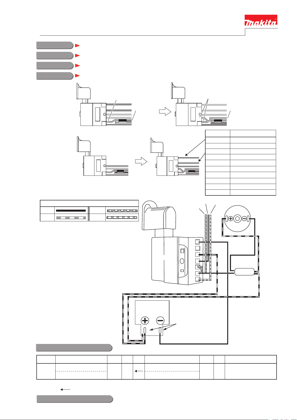
Change of Switch and the wiring
Y05777
February 2011
For Models
Country
Description
1. Wiring around
Switch in the
models
2. Switch supplied
to repair
BUB142, BUB182
All countries
Switch and the wiring have been changed to improve the repairability.
From M2 terminal
To diode
From M2 terminal and D terminal
Position
added
added
Two lead wires are added
for easy repairing.
BM1
B+
S
D
M2
Branched 1
Branched 2 + battery (red)
Branched 3
G
To diode
connected to (color)
- battery (black)
No connection
+ battery (red)
FET source (black)
FET drain (blue)
Diode (black)
+ motor (red)
- motor (black)
FET gate (yellow)
Black
Red
Color index of lead wires' sheath
Blue
Yellow
Battery
holder
Switch
FET source
FET drain
B-
M1
B+
S
D
M2
G
BUB142: using
receptacles
BUB182: soldering
FET gate
Motor
Diode
Interchangeability(I/C)
Current part New part Note
Switch
1
TP00000170
Interchangeability mark;
The arrow means that the new part can be substituted for the current.
Switch
TP00000174
Implementation
BUB142: From serial No. 29344 BUB182: From serial No. 40449
Q'tyItem No. I/CQ'ty
1017
 Loading...