

Page 1
T
ECHNICAL INFORMATION
PRODUCT
P 1/ 8
Model No.
Description
BLM430, LM430D
430mm Cordless Lawn Mower
CONCEPT AND MAIN APPLICATIONS
Models LM430D, BLM430, (HML01)*
with rotary blade cutting system.
Its main benefits are:
• Environment-friendly with zero emission and minimum noise pollution
• Compatible with both Makita 36V-2.6Ah Li-ion battery BL3626
and 36V-2.2Ah Li-ion battery BL3622A
• Compatible with Battery converters, BCV01 and BCV02
• Adjustable 13 cutting heights from 20mm to 75mm
• The storage space can be saved by standing the machine on its rear
end (See illustrated right.)
• Handle height is adjustable in 2 stages
This product is available in the variations listed below.
Model No.
LM430DWB
LM430DWBE
BLM430Z
BLM430RD 1 No
BLM430RDE 2BL3626 1
BLM430ZX2C No No
HML01Z*
HML01C1*
Note: All models also include the accessories listed below of "Standard equipment".
Charger
No
DC36RA BL3626
DC36RA
No
1 No NoNoNo No
1 1
Type Quantity
NoLM430DZ
BL3622A 1 NoDC36WA
BL3622A 2 1DC36WA
No
BL3622ADC36WA
1 is Cordless Lawn mower equipped
Battery
Battery
cover
No No
No NoNo NoNo
No
Battery
converter
No
No
No
No
No
BCV02
No
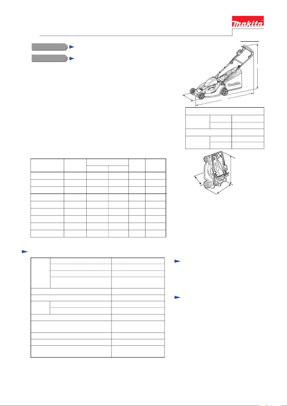
(19-1/4~19-3/4)
W
Length (L)
Width (W)
Height (H)
490~500
L
Dimensions: mm (inch)
minimum
maximum
minimum
maximum
1,450 (57)
1,490 (58-3/4)
460 (18-1/8)
950 (37-1/2)
1,020 (40-1/4)
810 (32)
(without Rear bag)
460 (18-1/8)
H
Specification
Cell
Voltage: V
Battery
Max output (W)
No load speed: min.
Blade
Cutting width: mm (") 430 (17)
Cutting height adjustment range: mm (")
Electric brake Yes
Soft start
Weight according to
EPTA-Procedure 01/2003*
*2: No load speed of the cutting tool
*3: with battery, blade, grass bag
*4: for North and Central American countries
*5: All countries except North and Central American countries
Capacity: Ah
Charging time (approx.): min.
ˉ¹=rpm*2
Type
3: kg (lbs)
Rotary type 2 tooth blade
20 - 75 (13/16 - 2-15/16),
Li-ion
36V
2.2/ 2.6
60 with DC36WA/
22 with DC36RA
580
3,600
24.0 (15/16)Inner diameter: mm (")
13 stages
Yes
18.1 (39.9)*
17.9 (39.4)*5
4,
Standard equipment
Socket wrench ........................................ 1
Blade 430 .............................................. 1
Note: The standard equipment for the tool
shown above may vary by country.
Optional accessories
Battery 3622A
Battery BL3626
Charger DC36WA
Fast charger DC36RA
Battery converter BCV01
Battery converter BCV02
Page 2
P 2/ 8
Repair
CAUTION: Repair the machine in accordance with “Instruction manual” or “Safety instructions”.
[1] NECESSARY REPAIRING TOOLS
DescriptionCode No. Use for
1R285
[2] ASSEMBLY/ DISASSEMBLY
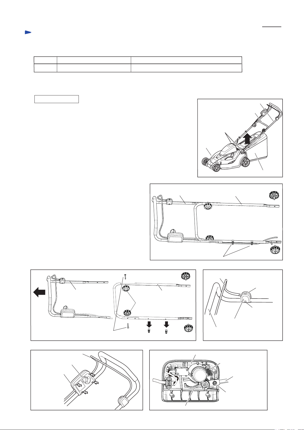
[2]-1. Handle section
DISASSEMBLING
(1) Lift and remove Rear bag section from Deck. (Fig. 1)
While holding Handle section (Lower pipe, Upper pipe complete, etc.),
loosen two M6 Thumb screws. (Fig. 1)
Handle section is removed. (Fig. 2)
(2) Remove two Holders 9-19 from Lower pipe.
Remove two M6 Thumb nuts and M6x50 two Cup hex square neck bolts,
and then separate Upper pipe complete from Lower pipe. (Fig. 3)
Lower pipe can be replaced.
(3) Loosen 4x18 Tapping screw, then remove Switch lever case and
Switch lever case cover. (Fig. 4)
(4) Loosen four 4x18 Tapping screws, then remove Switch box cover complete
and Switch box. (Fig. 5)
(5) Remove Tension spring 9, and then separate Lever
and M4x20 Pan head screw with WR (spring washer
and Flat washer) from Switch box and Switch lever.
Upper pipe complete and Lever can be replaced.
(Fig. 6)
Round bar for Arbor 11-50
removing Plane bearing 10 from Front/ Rear wheels
Fig. 1
Upper pipe complete
Lower pipe
M8x35 Thumb screw
(2 pcs.)
Deck
Fig. 2
Lower pipeUpper pipe complete
Rear bag complete
M8x35 Thumb
screw
Fig. 3
Upper pipe complete
M6x50 Cup hex square neck bolt
Fig. 5 Fig. 6
Switch lever
Switch box cover complete
Switch box
4x18 Tapping
screw (4 pcs.)
Lower pipe
M6 Thumb nut
(2 pcs.)
Holder 9-19 (2 pcs.)
Holder 9-19 (2 pcs.)
Switch box
Lever
M8x35
Thumb screw
Fig. 4
Switch lever
Switch lever case
4x18 Tapping
screw
Switch lever case cover
Upper pipe complete
Tension spring 9
Switch lever
M4x20 Pan head
screw with WR
Page 3
P 3/ 8
Repair
[2] ASSEMBLY/ DISASSEMBLY
[2]-1. Handle section (cont.)
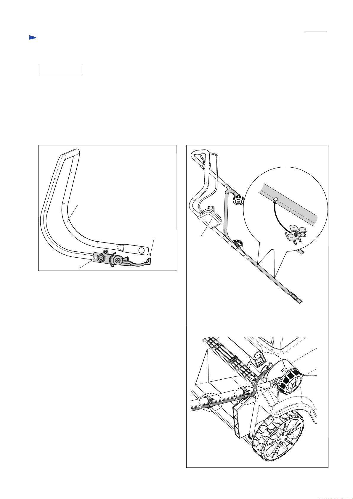
ASSEMBLING
Assemble Handle section in the reverse order of disassembly.
Note: • Face the top of Lever to the upper side when assembling Lever to Switch lever. (Fig. 7)
While holding the insert nut on lever so as not to separate, assemble Lever to Switch lever with M4x20 Pan head
screw with WR.
• Be careful to the direction of Compression spring 9. Refer to Fig. 6 in the previous page.
• Assemble Lower pipe to Upper pipe complete so that the two holes of Lower pipe come to Switch box side. (Fig. 8)
• Route Power supply cord along Lower pipe, and fix it in the lower holders of two Holders 9-19, then pass it over
Lower pipe near the hinge. (Fig. 8)
Fig. 7 Fig. 8
Switch lever
LeverInsert nut
The top of Lever
faces the upper side.
Switch box
The holes of Lower pipe
to attach Holders 9-19
Holder 9-19
Page 4

P 4/ 8
Repair
[2] ASSEMBLY/ DISASSEMBLY
[2]-2. Motor section
REPLACING
(1) Remove Blade.
(2) Pull Lock lever to release the locking of Battery cover complete, and then open Battery cover complete. (Fig. 11)
Remove the hinge of one side carefully, and separate it from Cowling. (Fig. 12)
And then, remove the other hinge in the same way.
(3) Remove Grip A by unscrewing two 5x25 Tapping screws. (Fig. 13)
(4) Remove six 4x18 Tapping screws. Shift Change lever to the position of Cutting height between 40 and 60mm. (Fig. 14)
(5) Pass Terminal housing through the square hole of Cowling without disconnecting the lead wires as drawn in Fig. 15.
Cowling can be removed toward the upper direction. (Fig. 15)
(6) Remove three M6x30 Pan head screws. DC motor can be replaced. (Fig. 16)
Fig. 11
Fig. 12
Battery cover complete
Fig. 13
5x25 Tapping screw
2
1
Grip A
hinges of Cowling with
Battery cover complete
Fig. 15
Terminal housing
Cowling
Fig. 14
4x18 Tapping
screw (6 pcs.)
Change lever
Terminal
housing
Square hole
of Cowling
Fig. 16
DC motor
M6x30 Pan head
screw with WR
(3 pcs.)
Page 5

Repair
[2] ASSEMBLY/ DISASSEMBLY
[2]-3. Change lever section
DISASSEMBLING
(1) Remove Cowling. (Refer to the previous page.)
(2) Shift Change lever to the position of grass cutting height 75mm.
(3) Detach the hook of Tension spring 16 from the projection of Deck using long-nose pliers. (Fig. 17)
(4) Put a wood under Deck to raise Wheels from the ground. (Fig. 18)
(5) Unscrew two 4x18 Tapping screws, and separate the pin of Connecting rod from the hole of Change lever,
and then remove Change lever section from Deck toward DC motor side. (Fig. 19)
(6) Remove Change lever cover, and then separate screws, bolt and nut as drawn in Fig. 20.
ASSEMBLING
Assemble Change lever section in the reverse order of disassembly.
Note: Lift Connecting rod and insert the pin into the hole of Connecting rod. (Fig. 21)
Fig. 17
Change lever
Fig. 19
P 5/ 8
hook of
Tension
spring 16
Fig. 18
Long-nose
pliers
projection of Deck
Adjust plate
Fig. 20
Flat washer 4
4x18 Tapping
screw
M6 Hex nut
Change lever
Compression spring 9
Flat washer 9
4x18 Tapping screw
(2 pcs.)
Change lever
Change
lever
cover
Sleeve 6
Wood
4x18 Tapping
screw (2 pcs.)
Fig. 21
hole of Change lever
Connecting rod
Adjust plate
pin of Connecting rod
M6x30
Hex bolt
Page 6

Repair
[2] ASSEMBLY/ DISASSEMBLY
[2]-4. Wheels
DISASSEMBLING
(1) Pull Front wheel caps straight out of Front wheels. (Fig. 22) Remove Rear wheel caps in the same way.
(2) Remove M8 Collared hex nuts and Front wheels from Front shaft. (Fig. 23)
Separate Rear wheels from Rear shaft in the same way.
(3) Tap the edge of each wheel with plastic hammer. Ball bearings 6200ZZ in the wheels are removed. (Fig. 24)
(4) Press each Plane bearing 10 out of the wheels with 1R285 as drawn in Fig. 25.
ASSEMBLING
Assemble each wheel section in the reverse order of disassembly. Refer to Fig. 26.
Fig. 22
Front wheel cap
Front
wheel
Fig. 23 Fig. 24
M8 Collared
hex nut
Front wheel
Ball bearing
6200ZZ
P 6/ 8
Fig. 25 Fig. 26
Arbor press
1R285
Ball bearing
6200ZZ
Front wheel
Plane bearing 10
M8 Collared hex nut
Front wheel cap
[2]-5. Connecting rod, Shafts
DISASSEMBLING
(1) Remove the assembled part of Lower pipe and Upper pipe complete.
(Refer to [2]-1. Handle section.)
(2) Remove Cowling. (Refer to [2]-2. Motor section.)
(3) Remove the assembled part of Change lever and Adjust plate.
(Refer to [2]-3. Change lever section.)
(4) Remove Front wheels and Rear wheels. (Refer to [2]-4. Wheels.)
As for the specifications for North America, remove two 4x18
Tapping screws and Protective shield. (Fig. 27)
(5) Loosen two M5-8 Hex lock nut and remove Connecting rod. (Fig. 28)
(6) Loosen six 4x18 Tapping screws. Front shaft and Rear shaft can be
removed. (Fig. 29)
Fig. 27
Fig. 28
M5-8 Hex lock nut (2 pcs.)
on Connecting rod
Fig. 29
4x18 Tapping screw (4 pcs.)
Front shaft
4x18 Tapping
screw (2 pcs.)
[ North America only]
Proactive
shield
Rear shaft
4x18 Tapping screw (2 pcs.)
Page 7

P 7/ 8
Repair
[2] ASSEMBLY/ DISASSEMBLY
[2]-5. Connecting rod, Shafts (cont.)
ASSEMBLING
Assemble each wheel section in the reverse order of disassembly.
Distinguish Front shaft from Rear shaft by the white paint. (Fig. 30)
Circuit diagram
Fig. D-1
Color index of lead wire’s sheath
Black Orange
White
Red Yellow
Blue
Lock key
Lead unit
Fig. 30
Rear shaft
Front shaft
white paint
Switch
Line filter
Terminal
Wiring diagram
Fig. D-2
Connect Lead wires as drawn below.
Pass them through the square hole of Cowling.
Controller
Route Lead wires in Switch box as drawn below so as not to
be pinched between ribs / bosses.
DC motor
Tension spring 9
Switch lever
Power
supply
cord
M4x20 Pan
head screw
Lever
Page 8

Wiring diagram (cont.)
Fig. D-3
To Switch
Lead unit
P 8/ 8
Terminal
Fix Lead wires (black, white) in
these Lead wire holders.
Connect Flag
receptacles as
drawn above.
Be careful to
the directions.
Controller
Fix Lead wires (red, blue) in
these Lead wire holders.
Fix Lead wires (red) in
these Lead wire holders.
Fix Lead wires (blue) in
these Lead wire holders.
DC motor
All Connectors, Line filters and Controller must be set in place using ribs on Deck as drawn above.
Be careful not to put any Lead wires on ribs drawn above.
 Loading...