


STR/CVR Series
Woodburning Fireplace
Homeowner's Installation
and Operating Manual
For Models:
STR33
STR36
STR42
CVR36
CVR42
For use in U.S./Canada
Underwriter's Laboratories
Report No. MH6018
DO NOT DISCARD THIS MANUAL: Retain for future use.
7412961 12/06 Rev. 17
STR/CVR Series Woodburning Fireplaces
Safety Information
PLEASE READ THIS MANUAL BEFORE INSTALLING AND USING FIREPLACE.
IMPORTANT: Read all instructions and warnings carefully before starting installation. Failure to follow these instructions may result in a possible fire hazard and will void the warranty.
Description
The STR/CVR Series fireplaces are multi-side solid fuel, woodburning fireplaces. These are radiant models only and include a preinstalled outside air kit.
Precautions
Majestic Fireplaces and component parts have been highly tested and will operate safely when installed in accordance with instructions provided in this manual. Carefully read and understand all instructions before beginning installation.
If you notice any damage to fireplace or component parts, immediately report damage to your Majestic Fireplaces dealer.
Only use CFM Corporation components or the warranty will be voided and a fire hazard may be created.
CFM Corporation warranty will be voided by and CFM
Corporation disclaims any responsibility for the following actions:
•Installation of any damaged fireplace or chimney component;
•Modification of fireplace, chimney assembly or any component parts thereof; (except for chase flashings as detailed in the Chimney Top installation instructions).
•Installation other than as instructed by CFM Corporation; or
•Installation and/or use of any component part not manufactured or approved by CFM Corporation in combination or assembly with a Majestic Fireplaces fireplace system, notwithstanding any independent testing laboratory or other third party approval of such component parts or accessory.
Any such action may possibly cause a fire hazard.
Consult local building codes to ensure that you are in compliance before installing the fireplace. Fireplaces must be vented to the out-of-doors.
Do not obstruct or modify air inlets/outlets in any manner.
Do not install combustible materials on any of the black fireplace surround.
Burn only solid wood fuel or gas logs.
Do not install a solid fuel burning insert or other products not specified for use with this fireplace.
Proposition 65 Warning: Fuels used in gas, woodburning or oil fired appliances, and the products of combustion of such fuels, contain chemicals known to the State of California to cause cancer, birth defects and other reproductive harm.
California Health & Safety Code Sec. 25249.6
WARNING: Check with your electronics manufacturer before installing a television or other electronic device above this fireplace.D
Drafts
The fireplace should not be located in areas that create drafts (ie: frequently opened doors and central heating air inlets/outlets) that hamper the normal flow of air into the fire.
Gas Logs
If you plan to install a gas log, the gas line should be installed before framing the fireplace. The gas line must be installed by a certified gas line installer.
STR33 / STR36 / STR42
CVR36 / CVR42
Listed
UL 127 / ULC-S610
Standard for Factory Built Fireplaces
Units: EC20R0, FC20R0, GC20R0, FD20R0, GD20R0
Table of Contents
Safety Information . . . . . . . . . . . . . . . . . . 2
Specifications and Framing . . . . . . . . . . 3
Parts Identification . . . . . . . . . . . . . . . . . 4
Chimney Requirements . . . . . . . . . . . . . 6
Planning Information . . . . . . . . . . . . . . . . 7
Installation . . . . . . . . . . . . . . . . . . . . . . . 8
Replacement Parts . . . . . . . . . . . . . . . . 20
Accessories . . . . . . . . . . . . . . . . . . . . . 22
2 |
7412961 |
STR/CVR Series Woodburning Fireplaces
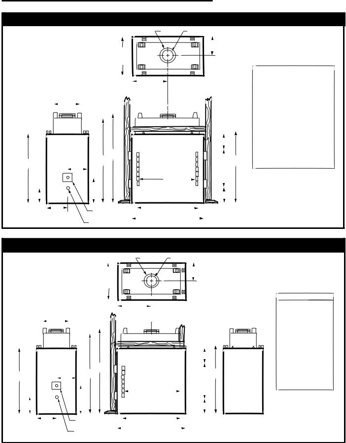
STR Series Woodburning Fireplace
FG
|
24" Total |
12" |
|
|
|
|
|
|
|
|
|
|
|
Framing Width |
Unit Width |
|
|
|
|
|
|
|
|
|
|
|
|
Will be 24" Minus |
|
|
STR33 |
STR36 |
STR42 |
|
2 x (Drywall Thickness) |
C |
|
A 33" |
36" |
42" |
|
|
|
838mm |
914mm |
1067mm |
||
|
|
|
B 37" |
40" |
46" |
|
|
|
|
940mm |
1016mm |
1168mm |
|
18 " |
|
|
C 18 " |
20" |
23" |
|
|
|
|
470mm |
508mm |
584mm |
|
|
|
|
D 49 " |
49 " |
53 " |
|
|
|
|
1267mm |
1267mm |
1368mm |
|
|
|
|
E 52 " |
52 " |
56 " |
|
|
|
|
1340mm |
1340mm |
1442mm |
|
|
|
|
F |
11" |
11" |
13 " |
|
|
7 " |
279mm |
279mm |
343mm |
|
|
|
|
G |
8" |
8" |
11" |
|
E |
|
203mm |
203mm |
279mm |
|
36" |
D |
37" |
J 26 " |
29 " |
35 " |
|
|
21" |
680mm |
741mm |
894mm |
||
12" |
|
|
|
|
|
|
|
|
J |
|
|
|
|
9 " |
14 " |
7 " |
|
|
|
|
|
|
|
|
|
||
12" |
Outside |
A |
|
|
|
|
|
Air |
B |
|
|
|
|
|
Gas Line Access |
|
|
|
|
|
|
|
|
|
|
|
|
Fig. 1 STR Series specifications and framing.
CVR Series Woodburning Fireplace
FG
|
|
" Total |
" |
|
|
|
|
|
|
|
|
|
|
|
|
Framing Width |
Unit Width |
|
|
|
|
|
|
|
|
|
|
|
|||
Will be 24" |
|
|
|
|
|
CVR36 |
CVR42 |
2 x (Drywall Thickness) |
|
|
A |
||||
|
|
|
C |
|
36" |
42" |
|
|
|
|
|
B |
914 mm |
1067 mm |
|
18 " |
|
|
|
40" |
46" |
||
|
|
|
|
1016 mm |
1168 mm |
||
|
|
|
|
|
C |
||
|
|
|
|
|
20" |
23" |
|
|
|
|
|
|
D |
508 mm |
584 mm |
|
|
|
|
|
49 " |
53 " |
|
|
|
|
|
|
E |
1267 mm |
1368 mm |
|
|
|
|
|
52 " |
56 " |
|
|
|
|
" |
|
F |
1340 mm |
1442 mm |
|
|
|
|
11" |
13 " |
||
|
|
E |
|
|
|||
|
|
|
|
G |
280 mm |
340 mm |
|
36" |
|
D |
|
37" |
8" |
11" |
|
" |
|
|
203 mm |
280 mm |
|||
|
|
" |
|
J |
29 " |
35 " |
|
|
|
|
|
||||
|
|
|
J |
|
|
741 mm |
895 mm |
|
|
" |
|
|
|
|
|
" |
|
" |
|
|
|
|
|
|
|
|
|
|
|
||
" |
|
Outside |
A |
|
|
|
|
|
|
Air |
B |
|
|
|
|
|
|
Gas Line |
|
|
|
|
|
|
|
Access |
|
|
|
|
|
Fig. 2 CVR Series specifications and framing.
7412961 |
3 |
STR/CVR Series Woodburning Fireplaces
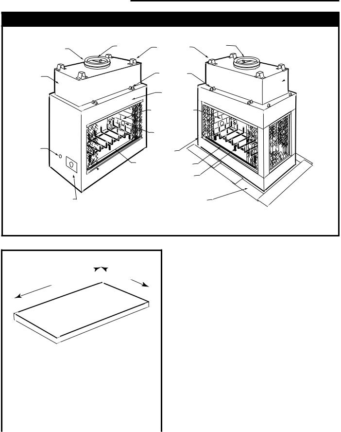
STR/CVR Series Woodburning Fireplace
Outer Collar |
Flue |
Collar |
Outer
Dome
Gas Line
Access
 Air Inlet
Outside Air Access
STR Fireplace
|
Header |
Flue |
|
Standoffs |
Damper |
|
Ledge |
|
|
Brackets |
|
|
Flue Damper |
|
|
Control |
|
|
(Inside) |
|
Brick liner on |
|
|
Sides and Hearth |
|
|
|
Gas Line |
|
|
Knock-out |
|
(Both Sides) |
|
|
Outside |
|
|
Control |
|
|
Firebox |
Hearth |
|
|
Wood Grate |
|
Metal Safety Strips, shown not in place (1, 2, or 3 Pieces)
Outer
 Dome
Dome


 Screen
CVR Fireplace
FP701
Fig. 3 STR/CVR Parts Identification.
A 

 B
B
|
|
FP1545 |
|
|
|
|
Front/Back Width |
Side Width |
|
A |
B |
STR33 |
26" |
17¹⁄ " |
|
(660 mm) |
(435 mm) |
STR/CVR36 |
29" |
17¹⁄ " |
|
(737 mm) |
(435 mm) |
STR/CVR42 |
35" |
17¹⁄ " |
|
(889 mm) |
(435 mm) |
Fig. 3a Hearth dimensions.
4 |
7412961 |
STR/CVR Series Woodburning Fireplaces
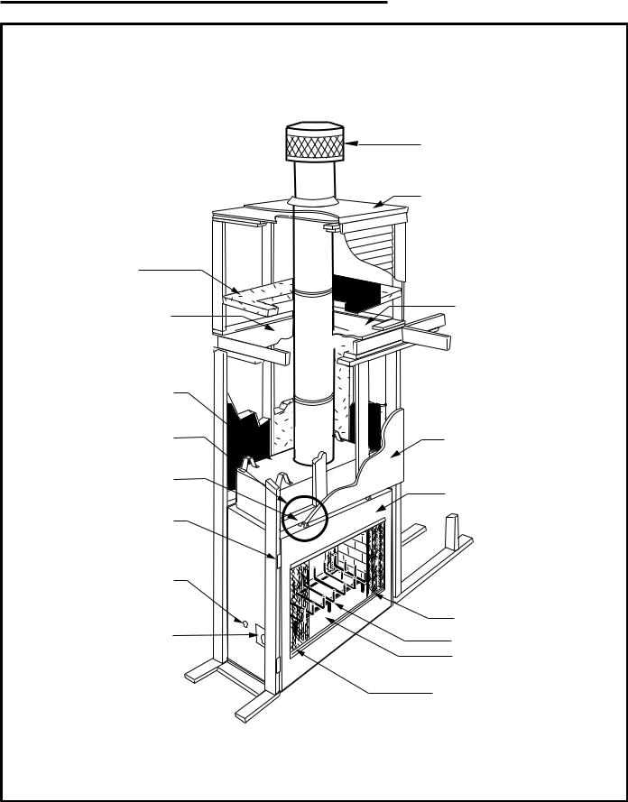
Chase Installation
Insulation methods shown are optional for cold climate, not a requirement for unit operation.
Termination Cap
Storm Collar
 Pan Flashing
Batt Insulation (cut out around firestop)
Draftstop
Firestop
Ceiling Level 

Outer Dome
Refer to Figures 21
and 26 for clearance Finish Wall information.
Ledge Brackets
Surround
Nailing Flange
Gas Access |
|
(both sides) |
|
|
Screen |
Outside Air Cover Plate |
Grate |
|
|
|
Firebox |
Outside Air
Control
FP704
Fig. 4 Fireplace and chase parts identification.
7412961 |
5 |
STR/CVR Series Woodburning Fireplaces
Chimney Requirements - Offset Installations
CHIMNEY FLUE EXIT
|
|
CHIMNEY |
|
|
|
|
|
SECTION |
|
|
|
|
|
ELBOW |
|
30˚ |
|
|
|
|
RETURN |
|
|
|
|
B |
|
|
|
A |
|
G |
ELBOW |
|
|
|
|
|
|
||
|
|
|
|
30˚ |
G |
|
|
|
|
|
|
D |
|
|
|
OFFSET |
|
E |
RISE |
|
ELBOW |
|
|
C |
6 FT. |
|
30˚ |
SKCS8 |
|
|
|
|
|||
|
|
H |
|
RETURN |
SUPPORT |
|
OFFSET |
|
ELBOW |
|
|
|
|
|
|
H |
|
|
|
|
|
30˚ |
|
B |
|
|
|
|
|
|
|
|
OFFSET |
|
|
|
|
|
|
ELBOW |
|
|
HEARTH |
|
|
|
|
|
FLOOR |
|
|
|
|
Example 1 |
|
Example 2 |
|
Example 3 |
|
Notes: G + H cannot exceed 20 feet. |
|
|
FP720 |
||
Air Space Clearances: |
|
|
|
|
|
SK8 (2-wall) = 1¹⁄ " , and 11CF (2-wall) = 2" |
|
|
|||
Illustration Key
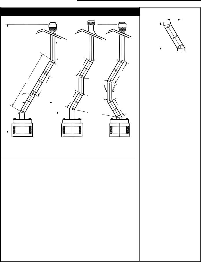
The following safety rules apply to offset installations (letters correspond with illustration above):
A. Height of the chimney is measured from the hearth to the chimney exit.
|
CVR / STR Series |
Maximum: |
90'0" |
Minimum: |
|
Without Elbows |
15'6" |
With 2 Elbows* |
17'6" |
With 4 Elbows* |
21' 0" |
B. Do not use more than 4 elbows per chimney.
Attach the straps of the return (top) elbow to a structural framing member.
The offset (first) elbow of any pair does not have straps.
* In Canada, two (2) SK845 are allowed.
C.The chimney cannot be more than 30˚ (45˚ in Canada) from the vertical plane in any installation*.
D.The maximum length of the angled run of the total chimney system is 20 feet. (G plus H cannot exceed 20 feet.)
E.A chimney support (Models TCS8A or 11CS) is required every 6 feet of angled run of chimney. Chimney supports are required for every 30 feet and 60 feet (SK8 & CF11 pipe) of vertical chimney height above the hearth.
Determine the offset distance of your chimney arrangement from the centerline of the fireplace to the centerline of the chimney where it is to pass through the first ceiling.
NOTE: This offset distance may not be your full offset distance. See Examples 2 and 3.
Fig. 5 Chimney system requirements.
OFFSET
RISE
|
|
|
|
|
|
|
|
FP282 |
|
30˚ Elbow Offsets |
|
||||||
|
|
|
|
|
|
|
|
|
|
1' |
1¹⁄' |
3' |
4' |
Chimney Support |
Offset |
|
Rise |
|
|
|
||||||
|
|
|
|
|
|
|
|
|
|
0 |
0 |
0 |
0 |
0 |
3" |
|
11" |
|
1 |
0 |
0 |
0 |
0 |
8¹⁄ " |
|
20" |
|
0 |
1 |
0 |
0 |
0 |
11¹⁄ " |
25¹⁄ " |
|
|
2 |
0 |
0 |
0 |
0 |
13¹⁄ " |
29¹⁄ " |
|
|
1 |
1 |
0 |
0 |
0 |
16¹⁄ " |
34¹⁄ " |
|
|
0 |
0 |
1 |
0 |
0 |
20¹⁄ " |
40³⁄ " |
|
|
2 |
1 |
0 |
0 |
0 |
21³⁄ " |
43¹⁄ " |
|
|
0 |
0 |
0 |
1 |
0 |
26¹⁄ " |
51¹⁄ " |
|
|
0 |
1 |
1 |
0 |
0 |
28¹⁄ " |
55¹⁄ " |
|
|
1 |
0 |
0 |
1 |
0 |
31¹⁄ " |
60¹⁄ ” |
|
|
0 |
1 |
0 |
1 |
0 |
34¹⁄ " |
65¹⁄ " |
|
|
0 |
0 |
2 |
0 |
0 |
37¹⁄ " |
70³⁄ " |
|
|
1 |
1 |
0 |
1 |
1 |
41¹⁄ " |
77³⁄ " |
|
|
0 |
0 |
1 |
1 |
1 |
45" |
83³⁄ " |
|
|
0 |
1 |
2 |
0 |
1 |
47¹⁄ " |
87¹⁄ " |
|
|
0 |
0 |
0 |
2 |
1 |
51" |
|
94" |
|
0 |
1 |
1 |
1 |
1 |
53¹⁄ " |
|
98" |
|
0 |
0 |
3 |
0 |
1 |
56¹⁄ " |
103¹⁄ " |
|
|
0 |
1 |
0 |
2 |
1 |
59¹⁄ " |
108¹⁄ " |
|
|
0 |
0 |
2 |
1 |
1 |
62¹⁄ " |
113¹⁄ " |
|
|
0 |
1 |
3 |
0 |
1 |
64¹⁄ " |
117¹⁄ " |
|
|
0 |
0 |
1 |
2 |
1 |
68¹⁄ " |
|
124" |
|
0 |
1 |
2 |
1 |
1 |
70¹⁄ " |
|
128" |
|
0 |
0 |
0 |
3 |
1 |
74¹⁄ " |
134¹⁄ " |
|
|
0 |
1 |
1 |
2 |
2 |
78" |
140³⁄ " |
|
|
0 |
0 |
3 |
1 |
2 |
81" |
|
146" |
|
0 |
1 |
0 |
3 |
2 |
84" |
151¹⁄ " |
|
|
0 |
0 |
2 |
2 |
2 |
87" |
156¹⁄ " |
|
|
0 |
1 |
3 |
1 |
2 |
89¹⁄ " |
160¹⁄ " |
|
|
0 |
0 |
1 |
3 |
2 |
93" |
166³⁄ " |
|
|
0 |
1 |
2 |
2 |
2 |
95¹⁄ " |
170³⁄ " |
|
|
0 |
0 |
0 |
4 |
2 |
99¹⁄ " |
177³⁄ " |
|
|
0 |
1 |
1 |
3 |
2 |
101¹⁄ " |
181³⁄ " |
|
|
0 |
0 |
3 |
2 |
2 |
104¹⁄ " |
186¹⁄ " |
|
|
0 |
1 |
0 |
4 |
2 |
107¹⁄ " |
191¹⁄ " |
|
|
0 |
0 |
2 |
3 |
2 |
110¹⁄ " |
196³⁄ " |
|
|
0 |
1 |
3 |
2 |
3 |
114" |
203¹⁄ " |
|
|
0 |
0 |
1 |
4 |
3 |
117³⁄ " |
209³⁄ " |
|
|
0 |
1 |
2 |
3 |
3 |
120" |
213¹⁄ " |
|
|
0 |
0 |
0 |
5 |
3 |
123³⁄ " |
|
220" |
|
|
|
|
|
|
|
|
|
6 |
7412961 |
STR/CVR Series Woodburning Fireplaces
Planning Information
Preplanning an installation is very important to ensure safety and to save time and money. An installer must predetermine where a fireplace will be set and how the chimney system will be run.
NOTE: STR33/36 and CVR36 models use CFM Corporation SK8 (2-wall) chimney systems. STR/CVR42 Fireplaces use only model 11CF chimney system.
Mounting the Fireplace
A fireplace may only be mounted on the following surfaces:
1.A flat combustible surface.
2.A raised wooden platform.
3.A concrete block or other solid object placed beneath each of the four (4) corners of the fireplace.
The fireplace must be spaced 1/2" (13mm) from a combustible back wall and 1/2" (13mm) from a combustible
side wall or support. (Page 14, Fig. 20)
Planning the Chimney Run
Determine how the chimney will be run, length of run and chimney components required to complete the job. (Fig. 6) Never install a chimney below minimum heights.
L |
|
T |
|
MODEL SK & |
TOTAL |
INSTALLED |
|
||||||
|
|
MODEL 11 CF |
LENGTH |
LENGTH |
||
|
|
|
2 WALL CHIMNEY |
(LT) |
(L1) |
|
|
|
|
||||
|
|
|
||||
L |
|
1 |
|
SK81 / 11CF1 |
" |
" |
|
||||||
|
|
|
SK818 / 11CF18 |
" |
" |
|
|
|
|||||
|
|
|
||||
L |
|
|
|
SK83 / 11CF3 |
" |
" |
|
|
|||||
|
|
|||||
|
1 |
|
SK84 / 11CF4 |
" |
" |
|
|
||||||
|
|
|
|
|
|
|
FP705
Fig. 6 Installed lengths of chimney sections.
In planning a chimney system, it is important to know:
1.The height of a chimney is measured from the hearth to the exit point on the termination.
2.A chimney cannot be offset more than 30° from a vertical plane.
3.A chimney may run straight up or it may be necessary to offset it to avoid obstructions.
4.The maximum length of an angled run (total chimney system) is 20' (6m).
5.No more than 2 offsets (4 total 30˚ elbows in U.S./or 2 total 45° elbows in Canada) per fireplace may be used.
6.A guy wire stabilizer is required for chimneys extending more than 6' (1.8m) above a roof line.
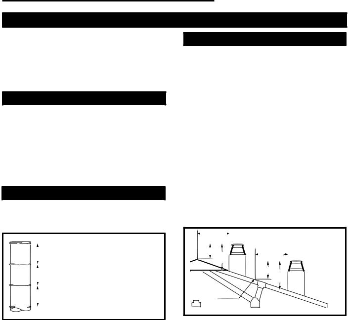
The Ten Foot Rule
Major U.S. building codes specify a minimum chimney height above the roof top. The “Ten Foot Rule” is a fire safety rule and not a draft rule. To ensure proper draft, it is recommended that you always meet or exceed the “Ten Foot Rule,” especially when installing a termination on a high pitch roof. (Fig. 7)
The key points of the "Ten Foot Rule" are:
1.If the horizontal distance from the chimney to the peak of the roof is 10' (3m) or less, the top of the chimney must be at least 2' (610mm) above the peak of the roof, but never less than 3' (914mm) in height above the highest point where it passes through the roof.
2.If a horizontal distance from the chimney to the peak of the roof is more than 10' (3m), a chimney height reference point is established on the surface of the roof a distance of 10' (3m) from the chimney in a horizontal plane. The top of the chimney must be at least 2' (610mm) above the reference point, but never less than 3' (914mm) in height above the highest point where it passes through the roof.
0 To 10' |
|
2' Min. 3' |
0 To 10' |
Min. |
|
|
2' Min. 3' |
|
Min. |
Reference
Point
AC246
Fig. 7 Ten Foot Rule illustration.
7412961 |
7 |
STR/CVR Series Woodburning Fireplaces
Chimney Supports
The chimney system is supported by the fireplace for vertical chimney heights less than 20' (6m) above the hearth. Chimney supports are required if the vertical height exceeds 20' (6m). Locate chimney supports at ceiling holes or other structural framing at 20' (6m)
heights. Spacing between chimney supports must not exceed 20' (6m). Use Chimney Support Model SKCS8 for SK8 chimney, and Model 11CS for 11CF chimney.
(NOTE: the chimney support can not be mounted directly to the fireplace.) Support provided by elbow straps fulfills the support requirement only if they are spaced as previously described. (A chimney support is 2¹⁄" (64mm) long when installed.)
Angled chimney runs require a support every 6' (1.8m) in addition to the elbow straps. Chimney supports are used for this function. (Fig. 9)
Chase Installation
A chase is a vertical box-like structure which encloses the fireplace and/or chimney. Chases are typically built on the outside of the house with fireplace opening cut into the outer wall of a room. (Page 5, Fig. 4)
If you need help in determining fireplace location or how the chimney system should be run, contact your Majestic dealer for assistance.
Chimney Support Strap
SKCS8 

FP284
Fig. 8 Chimney support installation
Installation
Insulating Fireplace Enclosure for Cold Climates
If you live in a cold climate, it is not required but highly recommended that you insulate fireplace enclosure to eliminate cold air penetration as much as possible.
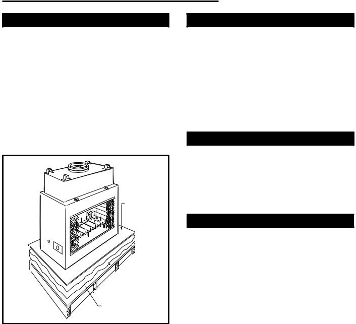
Insulate base of fireplace with a non-combustible insulation rated for a minimum of 300°F. Insulating is very important for outside wall installations over a concrete slab. If fireplace is installed on a platform, insulation should be placed on top of the platform before fireplace is set. (Fig. 9)
When a fireplace is installed in a chase or on a outside wall, enclosure should be treated like any outside wall in a home. Insulation should be installed on the inside wall as well as the outside wall(s). In a chase, it is also a good idea to install a firestop at the first ceiling level above the fireplace and enclose the chase with sheeting material. Insulation may then be installed above sheeting material to assure the space around the fireplace is totally protected. (Fig. 4)
When installing the chimney, DO NOT caulk between outer pipe and firestop. It is vital that some air be allowed to flow through this very thin gap.
CAUTION: WHEN INSTALLING A FIREPLACE IN AN INSULATED ENCLOSURE, BE SURE ALL
REQUIRED AIR SPACES ARE MAINTAINED. (Page 14, Fig. 20)
8 |
7412961 |
Framing
Framing can be constructed before or after the fireplace is set in place, however, most installers build the frame before setting the fireplace.
Frame fireplace with 2 x 4 lumber or heavier materials. Refer to framing dimensions in Figures 1, 2, 3 or 4 for basic fireplace specifications. Headers and support studs must be turned on end as illustrated on Page 5, Figure 4.
NOTE: Framing should be positioned to accommodate wall covering and fireplace facing material. Maintain
1/2" (13mm) air space between the outer dome and any combustible framing materials that may be supported by the ledge brackets. Refer to Figures 20 and 26 for details.
Hard, Flat
Surface


 Insulation
Plateform
FP706
Fig. 9 Insulating between platform and fireplace.
STR/CVR Series Woodburning Fireplaces
Chimney Set-up
Since you have already preplanned the chimney run, you should know exactly how the installation is to be accomplished — how much pipe is required, the
number of elbows, if any, and type of termination to be used.
CAUTION: REPORT TO YOUR DEALERS ANY PARTS DAMAGED IN SHIPMENT, SPECIFICALLY CHECK THE END CONNECTION OF CHIMNEY SECTIONS AND ELBOWS.
NOTE: STR33/36 and CVR36 models use CFM Corporation SK8 (2-wall) chimney systems. STR/CVR42 Fireplaces use only model 11CF chimney system.
Straight-Up Chimney Installation
To locate the centerline of the flue put the fireplace in final position and place a plumb bob from the ceiling to the center of the fireplace flue collar. Mark this spot on the ceiling. Draw a line through that mark to either side of the firebox and indicate dimension X to locate the side wall framing. (Fig. 10) Be sure to observe clearance requirements for side and parallel combustible walls as noted in Page 16, Figure 23.
Offset Installation
In order to clear an obstruction, it may be necessary to offset chimney from vertical. This is accomplished by using CFM Corporation elbows. Use the 30° Offset Elbow table on Page 6 to determine proper offset and parts required.
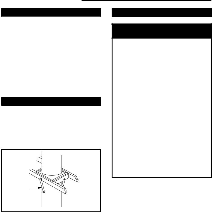
Each offset requires two (2) elbows. The second elbow is equipped with support straps. It is very important to install the second elbow in each offset as close to the ceiling or support as possible so that the elbow straps can be secured to framing members to help support the weight of the chimney.
Determine offset distance of your chimney arrangement from centerline of fireplace to centerline of chimney where it is to pass through ceiling.
Locate center point of the chimney on ceiling as though a straight up chimney arrangement is to be used. Measure your offset dimension from the chimney center point on the ceiling.
7412961 |
9 |
 Loading...