


Installation Manual
Installation and Appliance Setup
INSTALLER: Leave this manual with party responsible for use and operation. OWNER: Retain this manual for future reference.
NOTICE: DO NOT discard this manual!
Models:
RUBY25IN
RUBY25IL
RUBY30IN
RUBY30IL RUBY35IN RUBY35IL
This appliance may be installed as an OEM installation in manufactured home (USA only) or mobile home and must be installed in accordance with the manufacturer’s instructions and the Manufactured Home
Construction and Safety Standard, Title 24 CFR, Part 3280 in the United States, or the
Standard for Installation in Mobile Homes,
CAN/CSA Z240 MH Series, in Canada.
This appliance is only for use with the type(s) of gas indicated on the rating plate. This appliance is not convertible for use with other gases, unless a certified kit is used.
In the Commonwealth of Massachusetts installation must be performed by a licensed plumber or gas fitter.
See Table of Contents for location of additional Commonwealth of Massachusetts requirements.
 WARNING:
FIRE OR EXPLOSION HAZARD
Failure to follow safety warnings exactly could result in serious injury, death, or property damage.
•DO NOT store or use gasoline or other flammable vapors and liquids in the vicinity of this or any other appliance.
•What to do if you smell gas
-DO NOT try to light any appliance.
-DO NOT touch any electrical switch. DO NOT use any phone in your building.
-Leave the building immediately.
-Immediately call your gas supplier from a neighbor’s phone. Follow the gas supplier’s instructions.
-If you cannot reach your gas supplier, call the fire department.
•Installation and service must be performed by a qualified installer, service agency, or the gas supplier.
 DANGER
HOT GLASS WILL
CAUSE BURNS.
DO NOT TOUCH GLASS
UNTIL COOLED.
NEVER ALLOW CHILDREN
TO TOUCH GLASS.
A barrier designed to reduce the risk of burns from the hot viewing glass is provided with this appliance and shall be installed for the protection of children and other at-risk individuals.
Majestic • RUBY25IN, RUBY25IL, RUBY30IN, RUBY30IL, RUBY35IN, RUBY35IL Installation Manual • 2542-980 Rev. i • 9/19 |
1 |
|
 Safety Alert Key:
•DANGER! Indicates a hazardous situation which, if not avoided will result in death or serious injury.
•WARNING! Indicates a hazardous situation which, if not avoided could result in death or serious injury.
•CAUTION! Indicates a hazardous situation which, if not avoided, could result in minor or moderate injury.
•NOTICE: Used to address practices not related to personal injury.
Table of Contents
Installation Standard Work Checklist. . . . . . . . . . . . . . . . . . . . 3
1 Product Specific and Important Safety Information
A. Appliance Certification. . . . . . . . . . . . . . . . . . . . . . . . . . . . 4
B. Glass Specifications. . . . . . . . . . . . . . . . . . . . . . . . . . . . . . 4
C. BTU Specifications. . . . . . . . . . . . . . . . . . . . . . . . . . . . . . . 4
D. High Altitude Installations. . . . . . . . . . . . . . . . . . . . . . . . . . 4
E. Non-Combustible Materials Specification. . . . . . . . . . . . . . 4
F. Combustible Materials Specification . . . . . . . . . . . . . . . . . 4
G. Electrical Codes. . . . . . . . . . . . . . . . . . . . . . . . . . . . . . . . . 4
H. California. . . . . . . . . . . . . . . . . . . . . . . . . . . . . . . . . . . . . . 4
2 Getting Started
A. Design and Installation Considerations. . . . . . . . . . . . . . . 5
B. Good Faith Wall Surface. . . . . . . . . . . . . . . . . . . . . . . . . . 7
C. Tools and Supplies Needed. . . . . . . . . . . . . . . . . . . . . . . . 7
D. Inspect Appliance and Components. . . . . . . . . . . . . . . . . . 7
3 Appliance / Fireplace Requirements and
Clearances
A. Appliance/Decorative Front Dimension Diagrams. . . . . . . 8
B. Minimum Fireplace Opening . . . . . . . . . . . . . . . . . . . . . . 12
C. Wall Extension. . . . . . . . . . . . . . . . . . . . . . . . . . . . . . . . . 14
D. Mantel, Wall Projections, & Hearth Extensions. . . . . . . . 16
E. Hearth Extension. . . . . . . . . . . . . . . . . . . . . . . . . . . . . . . 17
4 Installation Preparation
A. Cleaning. . . . . . . . . . . . . . . . . . . . . . . . . . . . . . . . . . . . . . 19
B. Flue Damper. . . . . . . . . . . . . . . . . . . . . . . . . . . . . . . . . . . 19
C. Gas Line. . . . . . . . . . . . . . . . . . . . . . . . . . . . . . . . . . . . . . 19
D. Fireplace Conversion Notice. . . . . . . . . . . . . . . . . . . . . . 19
E. Electrical Outlet Box. . . . . . . . . . . . . . . . . . . . . . . . . . . . . 19
5 Installing Vent Pipe and Appliance
A. Vent Limits. . . . . . . . . . . . . . . . . . . . . . . . . . . . . . . . . . . . 20 B. Using Vertical Restrictor. . . . . . . . . . . . . . . . . . . . . . . . . . 21 C. Venting Components. . . . . . . . . . . . . . . . . . . . . . . . . . . . 22 D. Connecting to SLP. . . . . . . . . . . . . . . . . . . . . . . . . . . . . . 23 E. Connecting Vent Pipe. . . . . . . . . . . . . . . . . . . . . . . . . . . . 24 F. Placing, Securing and Leveling the Appliance. . . . . . . . . 25 G. Installing Termination Cap. . . . . . . . . . . . . . . . . . . . . . . . 26
6 Electrical Information
A. General Information. . . . . . . . . . . . . . . . . . . . . . . . . . . . . 27 B. Wiring Requirements. . . . . . . . . . . . . . . . . . . . . . . . . . . . 28 C. Installation / Service for Fan . . . . . . . . . . . . . . . . . . . . . . 29 D. Installation / Service for Halogens. . . . . . . . . . . . . . . . . . 30
7 Gas Information
A. Fuel Conversion. . . . . . . . . . . . . . . . . . . . . . . . . . . . . . . . 31
B. Gas Pressure. . . . . . . . . . . . . . . . . . . . . . . . . . . . . . . . . . 32
C. Gas Connection. . . . . . . . . . . . . . . . . . . . . . . . . . . . . . . . 32
D. High Altitude Installations. . . . . . . . . . . . . . . . . . . . . . . . . 33
E. Air Shutter Setting. . . . . . . . . . . . . . . . . . . . . . . . . . . . . . 33
F. Service / Replace Appliance Gas Valve. . . . . . . . . . . . . . 33
8 Finishing
A. Mantel, Wall Projections & Hearth Extensions. . . . . . . . . 34
B. Hearth Extension. . . . . . . . . . . . . . . . . . . . . . . . . . . . . . . 35
9 Appliance Setup
A. Fixed Glass Assembly. . . . . . . . . . . . . . . . . . . . . . . . . . . 37
B. Remove the Shipping Materials. . . . . . . . . . . . . . . . . . . . 38
C. Clean the Appliance. . . . . . . . . . . . . . . . . . . . . . . . . . . . . 38
D. Accessories. . . . . . . . . . . . . . . . . . . . . . . . . . . . . . . . . . . 38
E. Mystic Embers Placement. . . . . . . . . . . . . . . . . . . . . . . . 38
F. Ember Placement. . . . . . . . . . . . . . . . . . . . . . . . . . . . . . . 38
G. Install the Log Assembly. . . . . . . . . . . . . . . . . . . . . . . . . . 39
H. Install Decorative Front and Surround. . . . . . . . . . . . . . . 45
I. Appliance Break-In. . . . . . . . . . . . . . . . . . . . . . . . . . . . . . 46
J. Heat Management. . . . . . . . . . . . . . . . . . . . . . . . . . . . . . 46
10 Reference Materials
A. Vent Components. . . . . . . . . . . . . . . . . . . . . . . . . . . . . . . 47
B. Accessories. . . . . . . . . . . . . . . . . . . . . . . . . . . . . . . . . . . 48
= Contains updated information.
2 |
Majestic • RUBY25IN, RUBY25IL, RUBY30IN, RUBY30IL, RUBY35IN, RUBY35IL Installation Manual • 2542-980 Rev. i • 9/19 |
Installation Standard Work Checklist
ATTENTION INSTALLER:
Follow this Standard Work Checklist
This standard work checklist is to be used by the installer in conjunction with, not instead of, the instructions contained in this installation manual.
Customer: |
Date Installed: |
||
Lot/Address: |
|
|
Location of Fireplace: |
|
|
|
Installer: |
Model (circle one): |
RUBY25IN, RUBY25IL, RUBY30IN, |
|
Dealer/Distributor Phone # |
RUBY30IL, RUBY35IN, RUBY35IL |
Serial #: |
||
WARNING! Risk of Fire or Explosion! Failure to install appliance according to these instructions could lead to a fire or explosion.
Appliance Install |
YES |
IF NO, WHY? |
||
Verify fireplace is clean and remove/block open damper/modify |
|
|
|
|
damper for vent pipe clearance (Section 4). |
|
|
|
___________________________ |
|
|
|
||
Locate multi-purpose tool (Section 2). |
|
|
|
___________________________ |
|
|
|
||
|
|
|
||
Appliance is leveled and secured (Section 5.F). |
|
|
|
___________________________ |
|
|
|
||
|
|
|
||
Venting/Chimney Section 5 |
|
|
|
|
|
|
|
|
|
Exhaust and inlet flex vent pipe are properly formed and routed through |
|
|
|
|
existing fireplace damper. |
|
|
|
___________________________ |
Exhaust and inlet flex vent pipe are properly installed to the correct collars, |
|
|
|
|
sealed and secured to top slide plate and to the termination cap. |
|
|
|
___________________________ |
|
|
|
||
Vertical restrictors are properly set (if applicable). |
|
|
|
___________________________ |
Exterior roof flashing installed and sealed. |
|
|
|
___________________________ |
|
|
|
||
Termination cap installed, secured and sealed to top slide plate. |
|
|
|
___________________________ |
|
|
|
||
Electrical Section 6 |
|
|
|
|
Unswitched power (110-120 VAC) provided to the appliance. |
|
|
|
___________________________ |
|
|
|
||
Switch wires properly installed. |
|
|
|
___________________________ |
|
|
|
||
Gas Section 7 |
|
|
|
|
|
|
|
|
|
Proper appliance for fuel type. |
|
|
|
___________________________ |
|
|
|
||
Was a conversion performed? |
|
|
|
___________________________ |
|
|
|
||
Leak check performed and inlet pressure verified. |
|
|
|
___________________________ |
Verified proper air shutter setting for installation type. |
|
|
|
___________________________ |
|
|
|
||
Finishing Section 8 |
|
|
|
|
Combustible materials not installed in non-combustible areas. |
|
|
|
___________________________ |
|
|
|
||
Verified all clearances meet installation manual requirements. |
|
|
|
___________________________ |
Mantels and wall projections comply with installation manual requirements. |
|
|
|
___________________________ |
|
|
|
||
Appliance Setup Section 9 |
|
|
|
|
All packaging and protective materials removed (inside & outside of appliance). |
|
|
___________________________ |
|
|
|
|||
Refractories, logs, media and embers installed correctly. |
|
|
|
___________________________ |
|
|
|
||
Glass assembly and glass seal plate installed and secured. |
|
|
|
___________________________ |
|
|
|
||
Accessories installed properly. |
|
|
|
___________________________ |
|
|
|
||
|
|
|
||
Surround and decorative front properly installed. See instructions shipped |
|
|
|
|
|
|
|
|
|
with appliance front. |
|
|
|
___________________________ |
Manual bag and all of its contents are removed from inside/under |
|
|
|
|
the appliance and given to party responsible for use and operation. |
|
|
|
___________________________ |
|
|
|
||
Fireplace warning plate is attached to the existing woodburning fireplace. |
|
|
|
___________________________ |
|
|
|
||
Remote control is programmed, functions verified using remote control |
|
|
|
___________________________ |
|
|
|
||
instructions. |
|
|
|
|
Started appliance and verified no gas leaks exist. |
|
|
|
___________________________ |
Hearth & Home Technologies recommends the following: |
|
|
|
|
•Photographing the installation and copying this checklist for your file.
•That this checklist remain visible at all times on the appliance until the installation is complete.
Comments: Further description of the issues, who is responsible (Installer/ Builder/ Other Trades, etc) and corrective action needed _____________________________________________________________________________________
_________________________________________________________________________________________________
_________________________________________________________________________________________________
Comments Communicated to party responsible ____________________ by ______________________on ___________
= Contains updated information. |
(Builder / Gen. Contractor/) (Installer) |
(Date) |
|
|
2542-982B 5/19 |
Majestic • RUBY25IN, RUBY25IL, RUBY30IN, RUBY30IL, RUBY35IN, RUBY35IL Installation Manual • 2542-980 Rev. i • 9/19 |
3 |
|
1 Product Specific and Important Safety Information
A. Appliance Certification
MODELS: RUBY25IN, RUBY25IL, RUBY30IN, RUBY30IL, RUBY35IN, RUBY35IL
LABORATORY: Underwriters Laboratories, Inc. (UL) TYPE: Direct Vent Heater
STANDARD: ANSI Z21.88-2017 CSA 2.33-2017
This product is listed to ANSI standards for “Vented Gas Fireplace Heaters” and applicable sections of “Gas Burning Heating Appliances for Manufactured Homes and
Recreational Vehicles”, and “Gas Fired Appliances for Use at High Altitudes”.
Majestic gas inserts are designed for installations into solid fuel masonry or factory built fireplaces that have been installed in accordance with the National, Provincial, State and local building codes. Fireplaces are to be constructed of non-combustible materials and, in the absence of local or regional codes, meet criteria of NFPA211. No additional outside air source is required.
NOTICE: This installation must conform with local codes. In the absence of local codes you must comply with the National Fuel Gas Code, ANSI Z223.1-latest edition in the U.S.A. and the CAN/CGA B149 Installation Codes in Canada.
NOT INTENDED FOR USE AS A PRIMARY HEAT SOURCE.
This appliance is tested and approved as either supplemental room heat or as a decorative appliance. It should not be factored as primary heat in residential heating calculations.
B. Glass Specifications
This appliance is equipped with 5 mm ceramic glass. Replace glass only with 5 mm ceramic glass. Please contact your dealer for replacement glass.
C. BTU Specifications
Models |
Maximum |
Minimum |
Orifice |
||
Input |
Input |
Size |
|||
(U.S. or Canada) |
BTU/h |
BTU/h |
(DMS) |
||
RUBY25IN (NG) |
(0-2000 FT) |
27,000 |
18,900 |
40 |
|
|
|
|
|
|
|
RUBY25IL |
(0-2000 FT) |
25,000 |
17,500 |
53 |
|
(Propane) |
|||||
|
|
|
|
||
RUBY30IN (NG) |
(0-2000 FT) |
32,700 |
22,890 |
35 |
|
RUBY30IL |
(0-2000 FT) |
32,000 |
22,400 |
51 |
|
(Propane) |
|||||
|
|
|
|
||
RUBY35IN (NG) |
(0-2000 FT) |
35,000 |
24,500 |
33 |
|
RUBY35IL |
(0-2000 FT) |
35,000 |
24,500 |
50 |
|
(Propane) |
|||||
|
|
|
|
||
D. High Altitude Installations
NOTICE: If the heating value of the gas has been reduced, these rules do not apply. Check with your local gas utility or authorities having jurisdiction.
When installing above 2000 feet elevation:
•In the USA: Reduce input rate 4% for each 1000 feet above 2000 feet.
•InCANADA:Inputratingsarecertifiedwithoutaeduction of input rate for elevations up to 4500 feet (1370 m) above sea level. Please consult provincial and/or local authorities having jurisdiction for installations at elevations above 4500 feet (1370 m).
Check with your local gas utility to determine proper orifice size.
E. Non-Combustible Materials Specification
Material which will not ignite and burn. Such materials are those consisting entirely of steel, iron, brick, tile, concrete, slate, glass or plasters, or any combination thereof.
Materials that are reported as passing ASTM E 136,
Standard Test Method for Behavior of Materials in a Vertical Tube Furnace at 750 ºC shall be considered non-combustible materials.
F. Combustible Materials Specification
Materials made of or surfaced with wood, compressed paper, plant fibers, plastics, or other material that can ignite and burn, whether flame proofed or not, or plastered or unplastered shall be considered combustible materials.
G. Electrical Codes
NOTICE: This appliance must be electrically wired and grounded in accordance with local codes or, in the absence of local codes, with National Electric Code ANSI/NFPA 70-latest edition or the Canadian Electric
Code CSA C22.1.
•A 110-120 VAC circuit for this product must be pro - tected with ground-fault circuit-interrupter protection, in compliance with the applicable electrical codes, when it is installed in locations such as in bathrooms or near sinks.
H. California
WARNING: This product and the fuels used to operate this product (liquid propane or natural
gas), and the products of combustion of such fuels, can expose you to chemicals including benzene, which is known to the State of California to cause cancer and reproductive harm. For more information go to: www. P65Warnings.ca.gov.
4 |
Majestic • RUBY25IN, RUBY25IL, RUBY30IN, RUBY30IL, RUBY35IN, RUBY35IL Installation Manual • 2542-980 Rev. i • 9/19 |
2 Getting Started
A. Design and Installation Considerations
Majestic gas inserts are designed for installations into solid fuel masonry or UL127 listed factory built fireplaces. No additional outside air source is required.
Installation MUST comply with local, regional, state and national codes and regulations. Consult insurance carrier, local building inspector, fire officials or authorities having jurisdiction over restrictions, installation inspection and permits.
Prior to installing the gas insert:
•Ensure chimney is constructed of non-combustible materials.
•Ensure chimney is clean and in good working order.
•Ensure that all chimney cleanouts fit properly to prevent air leakage into chimney.
•Ensure combustible mantel and surround clearances comply with insert requirements.
•Ensure all joints are properly engaged and the chimney is properly secured.
•Determine minimum fireplace size. See Section 3.Aand 3.B.
•Determine gas supply piping requirements.
•Determine electrical wiring requirements.
•Determine finishing details.
•Determine whether optional accessories—devices such as a wall switch or remote control—are desired.
Installation and service of this appliance should be performed by qualifiedpersonnel.Hearth&HomeTechnologiesrecommends HHT Factory Trained or NFI certified professionals.
Improper installation, adjustment, alteration, service or maintenance can cause injury or property damage. For assistance or additional information, consult a qualified service technician, service agency or your dealer.
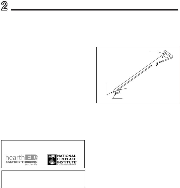
Multi-Purpose Tool
•See Figure 2.1 for multi-purpose tool functions and features.
•See Figure 2.2 for multi-purpose tool shipping location.
•See Figure 2.3 for multi-purpose tool storage location options.
GLASS CLIPS |
DISENGAGE |
SLIDE PLATE |
ENGAGE |
SLIDE PLATE |
GAS SHUT-OFF |
Figure 2.1 Multi-Purpose Tool
Majestic • RUBY25IN, RUBY25IL, RUBY30IN, RUBY30IL, RUBY35IN, RUBY35IL Installation Manual • 2542-980 Rev. i • 9/19 |
5 |
|
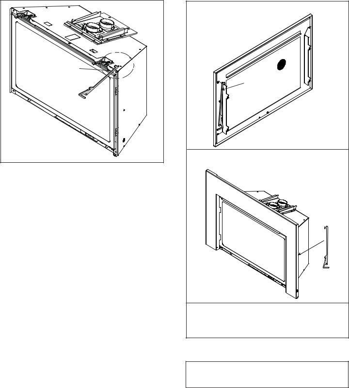
Multi-Purpose Tool - Shipping Location
MULTI-PURPOSE
TOOL SHIPPED ZIP-
TIED IN THIS AREA OF
THE APPLIANCE
Figure 2.2 Multi-Purpose Tool shipping Location
•Remove multi-purpose tool by cutting and discarding zip-tie.
•See Figure 2.3 for multi-purpose tool storage.
•See Figure 2.1 for multi-purpose tool features / functions.
Multi-Purpose Tool - Storage Options
OPTION A
Multi-purpose tool can be stored behind the appliance front.
MULTI-PURPOSE TOOL
NOTE: This is not an option for all Inside Fit (INFIT) fronts.
OPTION B
Multi-purpose tool can be stored behind the surround.
OPTION C
Multi-purpose tool can be stored in appliance manual bag.
Figure 2.3 Multi-Purpose Tool Storage Options
DO NOT store appliance manual bag in or around the appliance.
6 |
Majestic • RUBY25IN, RUBY25IL, RUBY30IN, RUBY30IL, RUBY35IN, RUBY35IL Installation Manual • 2542-980 Rev. i • 9/19 |
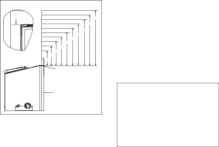
B. Good Faith Wall Surface
|
|
|
CEILING |
|
|
|
106 ºF |
SURROUND |
|
108 ºF |
|
OPENING |
|
|
52 IN. |
|
|
110 ºF |
|
|
|
115 ºF |
46 IN. |
|
|
120 ºF |
|
|
|
40 IN. |
|
|
|
125 ºF |
|
|
127 ºF |
34 IN. |
|
|
|
|
|
135 |
ºF |
28 IN. |
|
24 IN. |
|
||
138 ºF |
|
|
|
22 IN. |
|
||
151 ºF |
|
||
|
|
|
|
18 IN. |
|
|
|
16 IN. |
|
|
|
12 IN. |
|
|
|
|
MEASUREMENTS FROM TOP |
|
|
|
OF THE SURROUND OPENING |
|
|
APPLIANCE SURROUND |
|
||
Figure 2.4 Good Faith Wall Surface Temperatures Above Appliance
If installing a television (TV) above the appliance, see Section 3 of the appliance Owner’s Manual.
NOTICE: Temperatures listed above are taken with a temperature measuring probe as prescribed by the test standard used for appliance certification. Temperatures on walls or mantels taken with an infrared thermometer may yield increased temperatures of up to 30 ºF or more depending on the thermometer settings and material characteristics being measured. Use appropriate finishing materials that are able to withstand these conditions. For additional finishing guidelines, see Section 8.
C. Tools and Supplies Needed
Before beginning the installation be sure that the following tools and building supplies are available.
Tape measure |
Pliers |
Hammer |
Phillips screwdriver |
Voltmeter |
Electric drill and bits (1/4 in.) |
Gloves |
Safety glasses |
Level |
Reciprocating saw |
Manometer |
Flat blade screwdriver |
Stove cement / Aluminum foil tape
3/16 in. Allen wrench (Rear Leveling Legs)
Elongated pressure taps (Recommended)
Noncorrosive leak check solution
Caulking material (300 ºF minimum continuous exposure rating)
D. Inspect Appliance and Components
•Carefully remove the appliance and components from the packaging.
•The vent system components, decorative fronts and surrounds are shipped in separate packages.
•If packaged separately, the log set must be installed.
•Report to your dealer any parts damaged in shipment, particularly the condition of the glass.
•Read all of the instructions before starting the installation. Follow these instructions carefully during the installation to ensure maximum safety and benefit.
WARNING! Risk of Fire or Explosion! Damaged parts could impair safe operation. DO NOT install damaged, incomplete or substitute components. Keep appliance dry.
Hearth & HomeTechnologies disclaims any responsibility for, and the warranty will be voided by, the following actions:
•Installation and use of any damaged appliance or vent system component.
•Modification of the appliance or vent system.
•Installation other than as instructed by Hearth & Home Technologies.
•Improper positioning of the gas logs or the glass door.
•Installation and/or use of any component part not approved by Hearth & Home Technologies.
Any such action may cause a fire hazard.
WARNING! Risk of Fire, Explosion or Electric Shock! DO NOT use this appliance if any part has been under water. Call a qualified service technician to inspect the appliance and to replace any part of the control system and/or gas control which has been under water.
Majestic • RUBY25IN, RUBY25IL, RUBY30IN, RUBY30IL, RUBY35IN, RUBY35IL Installation Manual • 2542-980 Rev. i • 9/19 |
7 |
|

3 Appliance / Fireplace Requirements and Clearances
A. Appliance/Decorative Front Dimension Diagrams
Dimensions are actual appliance dimensions. Use for reference only. For addditional clearances refer to Sections 3.D and 3.E.
|
|
|
|
|
|
|
|
A |
|
|
|
|
|
|
|
|
|
|
|
|
|
|
|
H |
P |
|
|
|
|
|
|
|
|
|
|
|
N |
|
|
|
|
|
|
|
|
|
|
|
|
|
|
|
|
O |
|
|
|
|
|
|
|
|
|
|
|
|
|
|
|
|
|
|
G |
|
|
|
|
|
|
|
|
|
|
|
Q |
|
|
|
|
|
|
|
|
|
|
|
|
|
|
|
|
|
|
B |
|
|
|
|
|
|
|
|
|
|
|
|
|
|
|
TOP VIEW |
|
|
|
|
|
|
|
|
|
|
|
|
|
|
|
C |
|
|
|
|
|
|
|
F |
ELECTRICAL |
|
|
E |
|
|
|
D |
|
|
|
|
|
||
|
ACCESS |
|
|
|
|
|
|
|
|
|
|
|
I |
||
|
|
GAS LINE |
|
|
|
|
|
|
|
|
|
|
|||
|
|
|
|
|
|
|
|
|
|
|
|
|
|||
|
|
ACCESS |
|
|
|
|
|
|
|
|
|
|
|
||
|
|
|
|
|
|
|
|
|
|
R |
|
|
|
|
|
|
|
K |
M |
|
|
|
|
|
|
|
|
|
|
|
|
|
|
L |
J |
|
|
|
FRONT VIEW |
|
|
|
RIGHT SIDE |
|
|||
|
|
|
|
|
|
|
|
|
|
||||||
|
LEFT SIDE |
|
|
|
|
|
|
|
|
|
|
|
|||
|
|
MODEL DIMENSIONS |
|
|
|
MODEL DIMENSIONS |
|
|
|||||||
Location |
25 in. |
30 in. |
|
35 in. |
Location |
25 in. |
30 in. |
35 in. |
|||||||
IN |
MM |
IN |
MM |
IN |
MM |
IN |
MM |
IN |
MM |
IN |
MM |
||||
|
|
|
|||||||||||||
A |
|
14-5/8 |
372 |
19-5/8 |
499 |
24-5/8 |
626 |
J |
5-11/16 |
144 |
5-11/16 |
144 |
5-11/16 |
144 |
|
B |
|
26-1/8 |
664 |
31-1/8 |
791 |
36-1/8 |
918 |
K |
5-7/8 |
149 |
5-7/8 |
149 |
5-7/8 |
149 |
|
C |
|
22-1/2 |
572 |
27-1/2 |
699 |
32-1/2 |
826 |
L |
9 |
229 |
9 |
229 |
9 |
229 |
|
D |
|
12-7/16 |
316 |
15-15/16 |
405 |
19-3/8 |
492 |
M |
8-3/4 |
222 |
8-3/4 |
222 |
8-3/4 |
222 |
|
E |
|
17-1/16 |
433 |
20-3/4 |
527 |
24 |
610 |
N |
2-1/8 |
54 |
2-1/8 |
54 |
2-1/8 |
54 |
|
F |
|
16-5/8 |
422 |
20-1/8 |
511 |
23-5/8 |
600 |
O |
4-1/16 |
103 |
4-1/16 |
103 |
4-1/16 |
103 |
|
G* |
|
14-1/2 |
368 |
14-1/2 |
369 |
14-1/2 |
368 |
P |
5-3/4 |
146 |
5-3/4 |
146 |
5-3/4 |
146 |
|
H |
|
7-5/16 |
186 |
9-13/16 |
249 |
12-5/16 |
313 |
Q |
8-3/4 |
222 |
8-3/4 |
222 |
8-3/4 |
222 |
|
I |
|
15 |
381 |
18-15/16 |
481 |
21-7/16 |
545 |
R |
2-7/16 |
62 |
2-7/16 |
62 |
2-7/16 |
62 |
|
*Note: Location G is the appliance depth measurement, for installation depth reference Location E on |
|
||||||||||||||
|
|
Figure 3.7. |
|
|
|
|
|
|
|
|
|
|
|
||
Figure 3.1 Appliance Dimensions
8 |
Majestic • RUBY25IN, RUBY25IL, RUBY30IN, RUBY30IL, RUBY35IN, RUBY35IL Installation Manual • 2542-980 Rev. i • 9/19 |
DECORATIVE FRONTS - INSIDE FIT
*NOTICE: 1/2 inch gap must be maintained or components will overheat.
D
 A
A 
E |
F |
B |
C
*G
|
|
|
A |
B |
C |
D |
E |
F |
G |
|
RUBY25 |
INFIT-25 |
in. |
22-5/8 |
12-9/16 |
1-7/8 |
25-5/8 |
17 |
16-1/2 |
1/2 |
|
mm |
575 |
319 |
48 |
651 |
432 |
420 |
13 |
|||
|
|
|||||||||
RUBY30 |
INFIT-30 |
in. |
27-5/8 |
16-1/16 |
1-7/8 |
30-5/8 |
20-1/2 |
20 |
1/2 |
|
mm |
702 |
408 |
48 |
778 |
521 |
508 |
13 |
|||
|
|
|||||||||
RUBY35 |
INFIT-35 |
in. |
32-5/8 |
19-9/16 |
1-7/8 |
35-5/8 |
24 |
23-1/2 |
1/2 |
|
mm |
829 |
497 |
48 |
905 |
610 |
597 |
13 |
|||
|
|
|||||||||
|
|
|
|
|
|
|
|
|
|
Figure 3.2 Decorative Front Dimensions - Inside Fit |
|
Majestic • RUBY25IN, RUBY25IL, RUBY30IN, RUBY30IL, RUBY35IN, RUBY35IL Installation Manual • 2542-980 Rev. i • 9/19 |
9 |
|

DECORATIVE FRONTS - CLEAN SCREEN
*NOTICE: 1/2 inch gap must be maintained or components will overheat.
|
|
D |
|
|
A |
E |
F |
B |
|
|
C |
|
*G |
|
|
|
|
A |
B |
C |
D |
E |
F |
G |
|
RUBY25 |
CSFI25 |
in. |
27-3/8 |
15-1/8 |
3-1/2 |
31 |
20 |
19-1/2 |
1/2 |
|
mm |
695 |
384 |
89 |
787 |
508 |
495 |
13 |
|||
|
|
|||||||||
RUBY30 |
CSFI30 |
in. |
32-3/8 |
18-5/8 |
3-1/8 |
36 |
23-1/2 |
23 |
1/2 |
|
mm |
822 |
473 |
79 |
914 |
597 |
584 |
13 |
|||
|
|
|||||||||
RUBY35 |
CSFI35 |
in. |
37-3/8 |
22-1/8 |
3-1/8 |
41 |
27 |
26-1/2 |
1/2 |
|
mm |
949 |
562 |
79 |
1041 |
686 |
673 |
13 |
|||
|
|
Figure 3.3 Decorative Front Dimensions - Clean Screen
10 |
Majestic • RUBY25IN, RUBY25IL, RUBY30IN, RUBY30IL, RUBY35IN, RUBY35IL Installation Manual • 2542-980 Rev. i • 9/19 |
DECORATIVE FRONTS - CONTEMPORARY ARCH
*NOTICE: 1/2 inch gap must be maintained or components will overheat.
|
|
D |
|
|
A |
E |
F |
B |
|
|
C |
|
*G |
|
|
|
|
A |
B |
C |
D |
E |
F |
G |
|
RUBY25 |
CASFI25 |
in. |
24-1/16 |
12 |
3-7/8 |
31 |
20 |
19-1/2 |
1/2 |
|
mm |
610 |
305 |
98 |
787 |
508 |
495 |
13 |
|||
|
|
|||||||||
RUBY30 |
CASFI30 |
in. |
29-1/16 |
15-3/8 |
3-7/8 |
36 |
23-1/2 |
23 |
1/2 |
|
mm |
738 |
391 |
98 |
914 |
597 |
584 |
13 |
|||
|
|
|||||||||
RUBY35 |
CASFI35 |
in. |
34-1/16 |
18-7/8 |
3-7/8 |
41 |
27 |
26-1/2 |
1/2 |
|
mm |
865 |
479 |
98 |
1041 |
686 |
673 |
13 |
|||
|
|
Figure 3.4 Decorative Front Dimensions - CONTEMPORARY ARCH |
|
Majestic • RUBY25IN, RUBY25IL, RUBY30IN, RUBY30IL, RUBY35IN, RUBY35IL Installation Manual • 2542-980 Rev. i • 9/19 |
11 |
|
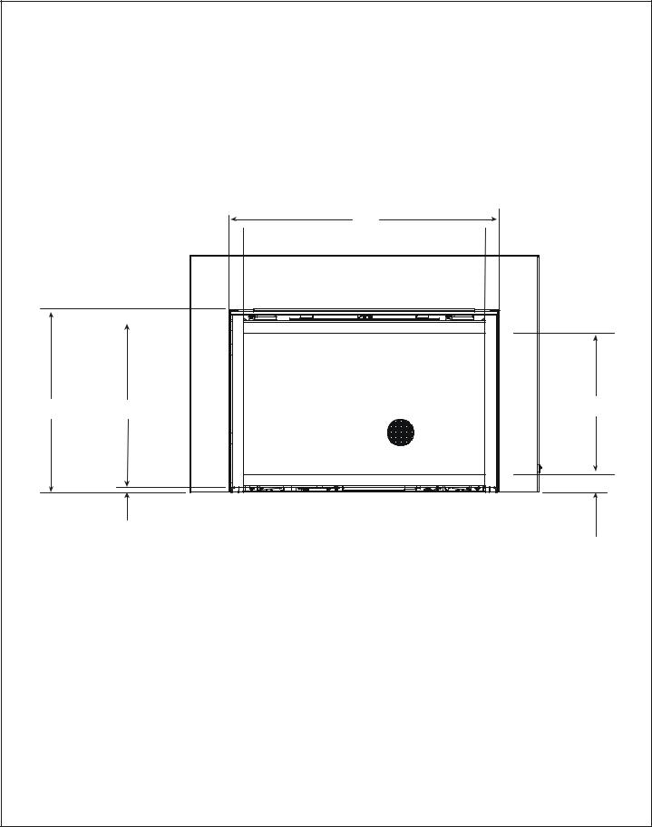
B. Minimum Fireplace Opening
Minimum fireplace opening requirements for a standard 3/4 inch deep surround are shown in Figure 3.7. For smaller openings, a custom surround is available.
WARNING! Risk of Fire or Burns! Provide adequate clearance around air openings and for service access.
Due to high temperatures, the appliance should be located out of traffic and away from furniture and draperies.
For Installation into a Zero Clearance Wood burning fireplace:
•The brick (refractory), glass doors, screen rails, screen mesh and log grates can be removed from a factory built firebox in order to gain minimum gas insert opening requirements.
•Any smoke shelves, shields and baffles may be removed from the factory built firebox if attached with mechanical fasteners.
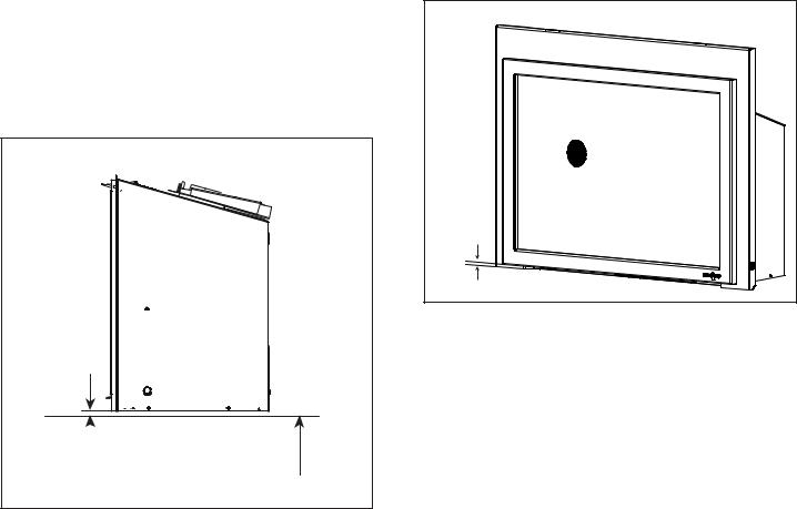
SIDE VIEW
 MINIMUM 1/4 IN. REQUIRED
COMBUSTIBLE FLOOR UNDERNEATH APPLIANCE
Figure 3.5 Solid Fuel Floor Clearance
•The appliance may not be placed directly on the base of the outer wrap, a 1/4 inch airspace MUST be provided between the insert and the floor of the outer wrap. Use the leveling legs to raise the insert a minimum of 1/4 inch. The original fireplace may never be returned to solid fuel in this condition. The sidewalls and top structure of the firebox may not be altered with the exception of removable baffles and dampers.
•The metal floor of the solid fuel firebox may be removed to facilitate the installation of the insert.
•Cutting of any sheet metal parts of the fireplace in which the gas fireplace insert is to be installed is prohibited, except the floor as tested for and as noted above.
•Aminimum 1/4 inch gap from the bottom of the appliance to the metal floor of the solid fuel firebox is REQUIRED.
See side view in Figure 3.5.
•Manufactured gas inserts can be installed as a zero clearance appliance. See Section 3C for clearance detail.
1/2 in. |
Figure 3.6 Minimum Required 1/2 in. Gap
NOTICE: 1/2 inch gap must be maintained or components will overheat.
12 |
Majestic • RUBY25IN, RUBY25IL, RUBY30IN, RUBY30IL, RUBY35IN, RUBY35IL Installation Manual • 2542-980 Rev. i • 9/19 |
TOP VIEW |
FRONT VIEW |
SIDE VIEW |
|
|
B |
|
|
F |
|
|
C |
E |
|
D |
|
F |
A |
|
|
|
3/4 in. |
|
|
MINIMUM FIREBOX OPENING
|
Location |
25 inch |
30 inch |
35 inch |
|||
|
|
|
|
|
|
|
|
|
Inches |
Millimeters |
Inches |
Millimeters |
Inches |
Millimeters |
|
|
|
||||||
|
|
|
|
|
|
|
|
A |
Opening Width - Rear |
15-1/8 |
384 |
20-1/8 |
511 |
25-1/8 |
638 |
|
|
|
|
|
|
|
|
B |
Opening Width - Front |
26-5/8 |
676 |
31-5/8 |
803 |
36-5/8 |
930 |
|
|
|
|
|
|
|
|
C |
Opening Height - Front |
17-5/16 |
439 |
21 |
533 |
24-1/4 |
616 |
|
|
|
|
|
|
|
|
D |
Opening Height - Rear |
15-1/4 |
387 |
19-3/16 |
487 |
21-11/16 |
551 |
|
|
|
|
|
|
|
|
E* |
Unit Opening Depth |
15 |
381 |
15 |
381 |
15 |
381 |
|
|
|
|
|
|
|
|
F |
Venting Depth - Front |
7-5/8 |
194 |
7-5/8 |
194 |
7-5/8 |
194 |
|
|
|
|
|
|
|
|
Note: Dimensions assume 1/4 inch clearance on all sides.
Note: If exhaust collar on insert and fireplace damper do not line up, add 4 inches (102 mm) to minimum fireplace height for bends in vent pipe.
*Unit depth is measured to the back of the surround to give the depth needed for installation. In addition to these dimensions, also reference Section 3.D and 3.E..
Figure 3.7 Firebox Opening - Standard Surround - 3/4 in.
Custom Surrounds
Custom surrounds are available. See your dealer for information. Standard surrounds are 3/4 inches deep. Custom surrounds are available up to 3 inches deep. A 3 inch deep surround would reduce the unit opening depth (E*) by 2-1/4 inches (3 in. - 3/4 in. = 2-1/4 in).
On Site Custom Surrounds
On site custom surrounds are available. See your dealer for information. On site custom surrounds are flush and have no depth. A flush surround would increase the unit opening depth (E*) by 3/4 inch.
Majestic • RUBY25IN, RUBY25IL, RUBY30IN, RUBY30IL, RUBY35IN, RUBY35IL Installation Manual • 2542-980 Rev. i • 9/19 |
13 |
|
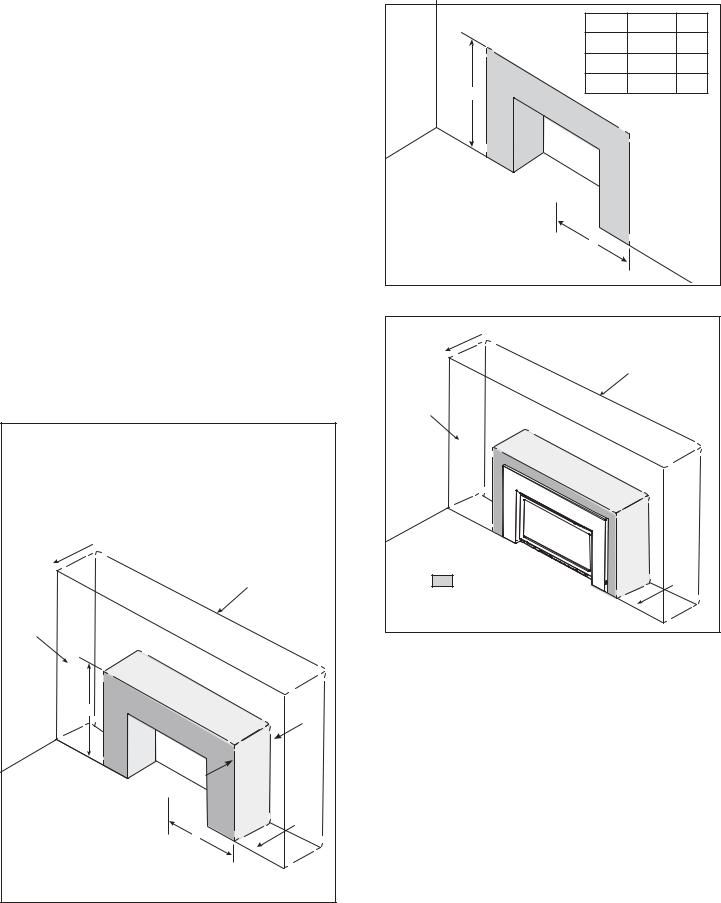
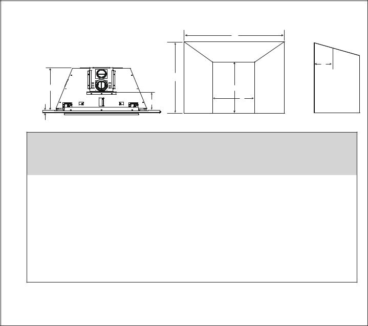
C. Wall Extension
Surrounds MUST overlap wall extension.
A non-combustible wall extension can be used to cover an existing masonry surface. Wall extensions are typically used to improve cosmetics.
WARNING! Risk of Fire! Comply with all minimum clearances to combustibles as specified. Framing or finishing material closer than the minimums listed must be constructed entirely of noncombustible materials (i.e., steel studs, concrete board, etc).
Combustible facings must not extend behind the insert surround. See Section 1.E and 1.F.
Non-Combustible Materials Specification
Material which will not ignite and burn. Such materials are those consisting entirely of steel, iron, brick, tile, concrete, slate, glass or plasters, or any combination thereof.
Materials that are reported as passing ASTM E 136,
Standard Test Method for Behavior of Materials in a Vertical Tube Furnace at 750 ºC.
UNIT |
X |
Y |
25 in. |
31 |
52 |
|
|
|
30 in. |
33-1/2 |
56 |
|
|
|
35 in. |
36 |
60 |
WALL EXTENSION
EXISTING MASONRY WALL
NEW WALL
FACE
Y |
NON |
|
|
|
|
|
|
- |
|
|
|
||
|
|
|
COMBUSTIBLE |
ZONE |
.max |
|
|
|
|
|
|
|
. |
|
|
|
|
|
|
in |
|
|
|
|
|
|
DEPTH |
|
|
|
|
|
|
12 |
FLOOR |
|
|
|
|
|
|
X - Measure from center |
|
C |
x |
|
||
|
L |
|
|
|
||
of firebox opening. |
|
|
|
|
|
|
Y - Measure from the |
|
|
|
|
|
|
bottom of the appliance.
Figure 3.8 Non-Combustible Framing Requirement
|
|
|
UNIT |
X |
Y |
|
|
|
25 in. |
31 |
52 |
|
|
|
30 in. |
33-1/2 |
56 |
Y |
NON- |
|
35 in. |
36 |
60 |
|
|
|
|
||
COMBUSTIBLE |
|
|
|
||
|
ZONE |
|
|
||
|
|
|
|
|
|
FLOOR |
|
|
|
|
|
X - Measure from center |
|
|
|
|
|
of firebox opening. |
|
C |
x |
|
|
Y - Measure from the |
|
L |
|
|
|
|
|
|
|
|
|
bottom of the appliance. |
|
|
|
|
|
Figure 3.9 Non-Combustible Facing Requirement
WALL EXTENSION |
EXISTING MASONRY WALL |
NEW WALL |
FACE |
FLOOR |
NON-COMBUSTIBLE ZONE |
Figure 3.10 Non-Combustible Framing / Facing Requirement
•Facing and/or finishing materials must not interfere with air flow through decorative fronts.
•Facing and/or finishing materials must never overhang into the glass opening.
•Observe all clearances when applying combustible materials.
•Maximum depth of wall extension is 12 inches. This may be limited by the flex pipe’s ability to connect to the starting collar.
•Covering combustible materials with non-combustible materials does not qualify material as non-combustible.
WARNING! Risk of Fire! DO NOT apply combustible materials beyond the minimum clearances. Comply with all minimum clearances to combustibles as specified in this manual. Overlapping materials could ignite and will interfere with proper operation of decorative fronts.
14 |
Majestic • RUBY25IN, RUBY25IL, RUBY30IN, RUBY30IL, RUBY35IN, RUBY35IL Installation Manual • 2542-980 Rev. i • 9/19 |

STEEL STUD |
|
SIDE VIEW |
|
12 in. |
MASONRY |
WALL |
|
MAXIMUM |
|
FACING |
|
|
STEEL STUD |
|
END VIEW |
SEAL |
|
TRANSITION |
|
APPLIANCE |
|
Figure 3.11 Transition Sealing Detail for Wall Extensions (Side View)
Wall Extension
Wall extension must be sealed to existing masonry wall. See Figure 3.11. Framing studs may not sit flush against existing masonry wall. In order to keep heat from escaping behind the wall this transition must be sealed.
• Seal with a high temperature silicone 300 °F. and / or
•Packing insulation into voids between the masonry wall and steel studs is acceptable.
Note: Combustible materials may be used to seal wall extension to existing masonry wall as long as it is outside the non-combustible zone.
Painting
If desired finishing includes a painted wall, a high-quality 100% acrylic latex paint with a high-quality latex primer base coat are recommended around the appliance to limit discoloration. Oil-based or standard acrylic paints may be more prone to discoloration due to heat exposure.
Drywall Joint-Crack Prevention and Repair
Drywall joints around the fireplace will be affected by exposure to elevated temperatures, along with other environmental, structural factors due to new construction, and methods used to install and finish the drywall. If a crack does emerge adjacent to the fireplace, it can be permanently repaired by filling it with a paintable latex caulk, followed by repainting.
Some movement of the screws used to secure the noncombustible board to the appliance/surround framing is expected. If a blemish begins to show over a screw head, sand the surface to remove the blemish and repaint.
NOTE: Concealed sections of 3 in. flex pipe must be contained inside existing masonary fireplace flue vent or installed into an existing wood burning vent system.
Majestic • RUBY25IN, RUBY25IL, RUBY30IN, RUBY30IL, RUBY35IN, RUBY35IL Installation Manual • 2542-980 Rev. i • 9/19 |
15 |
|
 Loading...