


Magic Chef CG34700BDT, PGR5715BDW, PGR5715BDQ, PGR5710BDW, PGR5710BDQ Installation Instructions
...Gas Conversion
General
All ranges are equipped with fixed orifices and with a convertible appliance pressure regulator. The unit model number plate states which gas it is adjusted for at the factory. To convert the unit to either Natural gas or LP gas will require the replacement of the orifice hoods, and the adjustment of the air shutters on the burners and adjustment of the appliance pressure regulator converter cap.
Inlet pressure to the appliance pressure regulator should be as follows for checking the appliance pressure regulator setting:
INLET PRESSURE IN |
NATURAL |
LP |
INCHES OF WATER COLUMN |
GAS |
GAS |
Minimum |
5 |
11 |
Maximum |
14 |
14 |
Appliance Pressure Regulator Conversion
The unit appliance pressure regulator must be set to match the type gas supply used. If converting from natural gas to LP gas, the appliance pressure regulator must be converted to regulate LP gas. If converting from LP gas to natural gas, the appliance pressure regulator must be converted to regulate natural gas.
To access the regulator from front of range, remove the storage drawer or warming drawer.
To remove the storage drawer: Pull out to the first stop position. Lift up front of drawer and pull to the second position, grasp sides and lift up and out to remove drawer.
To convert the appliance pressure regulator from one gas to another, remove plastic dust cover from cap nut on top of appliance pressure regulator. Remove cap nut from appliance pressure regulator (plastic dust cover comes off with nut).
IMPORTANT: Remove plastic dust cover from cap nut and reinstall on opposite side of cap nut.
Reinstall cap nut to appliance pressure regulator and replace dust cover.
CAUTION: Be sure marking for the type of gas to which appliance pressure regulator has just been converted is visible in top of cap nut before replacing plastic dust cover. (See figure 1.)
FIGURE 1
To replace the storage drawer: Fit the drawer rollers onto the rails. Lift up drawer front and gently push in to first stop position. Lift up and continue to slide drawer to the closed position.
8101P553-60 (12-03-00)

Orifice Conversion
To convert this unit to LP gas from Natural gas will require the exchange of orifice hoods.
IMPORTANT: Save all natural orifice hoods that are removed.
Oven Burner Conversion
Remove all oven racks.
1.Bake Burner
a. Remove oven bottom (figure 2).
CLIP
FIGURE 2
b.Remove screw from the bake burner (figure 3).
c.Remove the bake burner from the orifice fitting. CAUTION: The igniter is fragile. Take care not to damage it.
d.Gently lay the bake burner in the bottom of the range.
e.Remove warming drawer or storage drawer.
f.Remove access cover to orifice (figure 4).
g.Remove the bake orifice hood with a ½ (12.7 mm) socket wrench counter-clockwise.
h.Place the black-colored orifice stamped 1.3 on the
fitting turning it clockwise by hand approximately one turn. Tighten the orifice hood with a ½ (12.7 mm) socket wrench clockwise approximately 2½ turns.
i.Replace the bake burner.
j.Replace the oven bottom.
k.Replace access cover and drawer.
SCREW
SCREW
FIGURE 4
2.Broil Burner Conversion
a.Remove the screw from the broil burner.
b.Gently lay the broil burner on the oven bottom. CAUTION: The igniter is fragile. Take care not to damage it.
c.Remove the broil orifice hood with a ½ (12.7 mm) socket wrench.
d.Place the green-colored orifice hood stamped 57 on the fitting turning the orifice clockwise by hand
approximately one turn. Tighten the broil orifice hood with a ½ (12.7 mm) socket wrench clockwise approximately 2½ turns.
e.Replace broil burner.
f.Replace oven racks.
Surface Burner Conversion
1.Remove all grates.
2.Mark ignitor location on the main top with a pencil. This mark on the main top is used as a reference point when replacing the burner assembly to ensure that the burner is tightened to its original position.
3.Place burner wrench (part no. 8312D075-60, available from the dealer or authorized service agency) over the surface burner assembly with the ignitor positioned inside the gap in the wrench ring (figure 5). This prevents the ignitor from being damaged when the wrench grips the burner assembly. Rotate the burner assembly approximately one-eighth turn counter-clockwise and lift from the main top.
FIGURE 3
2
4.Remove the surface burner orifice hood with a ½ (12.7 mm) socket wrench counter-clockwise.
IMPORTANT: Save all natural orifice hoods that are removed.
5.Place the corresponding orifice hood on the burner fitting according to figure 6. Turn the orifice hood
clockwise by hand approximately one turn. Tighten the orifice hood clockwise with a ½ socket wrench approximately 2½ turns.
6.Replace the burner assembly in the main top and rotate one-eighth turn clockwise using the burner wrench until the burner locks in place with the igniter aligned with the reference mark on the main top.
7.Repeat steps 3 through 6 until all orifice hoods have been changed.
7.5K BTU NATURAL (NO COLOR) |
7.5K BTU NATURAL (NO COLOR) |
|
REPLACE WITH ORIFICE (NO COLOR) |
||
REPLACE WITH ORIFICE (NO COLOR) |
||
STAMPED .85 FOR LP |
||
STAMPED .85 FOR LP |
||
|
9.2K BTU NATURAL (NO COLOR) |
12K BTU NATURAL (RED) |
|
REPLACE WITH ORIFICE (RED) |
||
REPLACE WITH ORIFICE (NO COLOR) |
||
STAMPED .65 FOR LP |
||
STAMPED .85 FOR LP |
||
|
FIGURE 6
To Reassemble:
Replace burner assembly in main top and rotate approximately one-eighth turn clockwise using burner wrench until burner locks into position with ignitor aligned with reference mark on main top.
ORIFICE HOOD
7
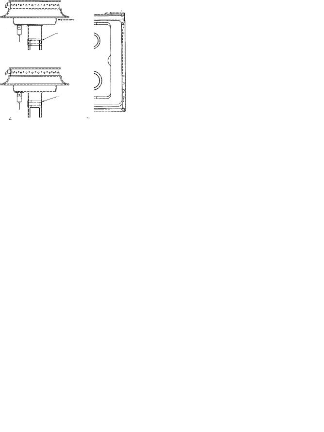
Air Shutter - Oven Burner
a.The approximate length of the flame of oven burner is a 1/2 inch distinct inner blue flame, figure 8.
FIGURE
b.Oven burner flame can be checked as follows:
1.Yellow flame on burner - open burner air shutter to the widest opening that will not cause the flame to lift or blow off the burner when cold. (See #2 on figure 9.)
2.Distinct blue flame but lifting - close burner air shutter to the point where it will not cause the flame to lift or blow off the burner when cold. (See #2 on figure 9.)
3 LOCK SCREW
AIR SHUTTER
2
1 ORIFICE HOOD
c.The oven burner air shutter adjustment is the same on ranges with a gas pilot or electric ignition.
d.Sealed burner adjustment. Adjust the air shutter for the appropriate gas according to figure 10.
AIR SHUTTER
NATURAL POSITION
FIGURE 10
AIR SHUTTER
LP POSITION
3
 Loading...