

Page 1
FUSSION SERIES PARTS LIST
RECONE KIT FS18-PWR1800S: PART # 11480011
RECONE KIT FS18-PWR1800S: PART # 11480011
RECONE KIT FS12W-PWR3000 PART# 21110240
RECONE KIT FSTC8-PWR3000 PART# 21110260
PWR 1800-S
PART# DESCRIPTION QTY BOARD PAGE NUMBER
21110230 WOOFER FS18-PWR1800S 1
33090460 HANDLE CASE 4
33090700 SPKR CABINET 1
33900120 SIDE HANDLE BAR 4
33920590 SIDE HANDLE GRIP 4
33221400 PROTECTION GRILLE 1
33951990 LBL LOGO FRONT 1
33952650 LBL FUSSION BLUE 1
43900240 CABINET FEET 4
PWR 1800-SA
21110230 WOOFER FS18-PWR1800S 1
23020480 PCB ASSY LED 1
23103220 PCB PWR 1800-SA AMP 230V 1
23103300 PCB PWR 1800-SA AMP 115V 1
03528300 INPUT BOARD 1 MN 052 103 SEE PAGE 13
03528302 CAP BOARD FOR LF AMP 2 MN 051 401 SEE PAGE 11
03528303 SA XFMR 230V-115V 1
03528312 1500 WATT AMPLIFIER CARD 2 MN 042 101 SEE PAGE 2-3
03528313 AC SOFT START INPUT BOARD 1 MN 052 105 SEE PAGE 14
33090460 HANDLE CASE 4
33090740 SPKR CABINET 1
33221400 PROTECTION GRILLE 1
33900120 SIDE HANDLE BAR 4
33920590 SIDE HANDLE GRIP 4
33951530 LBL LOGO SPKR FRONT 1
33952650 LBL FUSSION BLUE 1
33961020 OWNER’S MANUAL 1
43900240 CABINET FEET 4
43900260 VENT PLASTIC GRILLE 4
PWR 3000
21110240 WOOFER FS12W-PWR3000 1
21110260 WOOFER FSTC8-PWR3000 1
23020480 PCB ASSY LED 1
23103160 PCB PWR 3000 AMPLIFIER 230 V 1
23103300 PCB PWR 3000 AMPLIFIER 115 V 1
03528304 300 WATT MR AMPLIFIER CARD 1 MN 042 109 SEE PAGE 4-5
03528305 100 WATT HF AMPLIFIER CARD 1 MN 042 110 SEE PAGE 6-7
03528306 CONTROL CARD 1 MN 044 501 SEE PAGE 8-9
03528307 INPUT BOARD 1 MN 052 102 SEE PAGE 13
03528308 CAP BOARD FOR LF AMP 1 MN 051 402 SEE PAGE 10
03528301 CAP BOARD FOR MF/HF AMP 1 MN 051 403 SEE PAGE 12
03528309 POWER SUPPLY 230V-115V 1
03528310 300 WATT MR TRANSFORMER 1
03528311 150 WATT HF TRANSFORMER 1
03528312 1500 WATT AMPLIFIER CARD 1 MN 042 101 SEE PAGE 2-3
03528313 AC SOFT START INPUT BOARD 1 MN 052 106 SEE PAGE 14
25110230 TWEETER N850-PWR 1800 1
31920430 HEATSINK PWR3000 1
33090460 HANDLE CASE 4
33090760 SPKR CABINET 1
33951530 LBL LOGO SPKR FRONT 1
33952650 LBL FUSSION BLUE 1
33141040 HORN H6000 1
33221390 PROTECTION GRILLE 1
33900120 SIDE HANDLE BAR 4
33920590 SIDE HANDLE GRIP 4
33961000 OWNER’S MANUAL 1
43900170 HORN ME90 1
43900240 CABINET FEET 4
43900260 VENT PLASTIC GRILLE 4
©2000 All rights reserved, Mackie Designs Inc.FUSSION Service Manual
MASTER PARTS LIST
1
Page 2
INPUT
GND
NEGATIVE IN
POSITIVE IN
GND
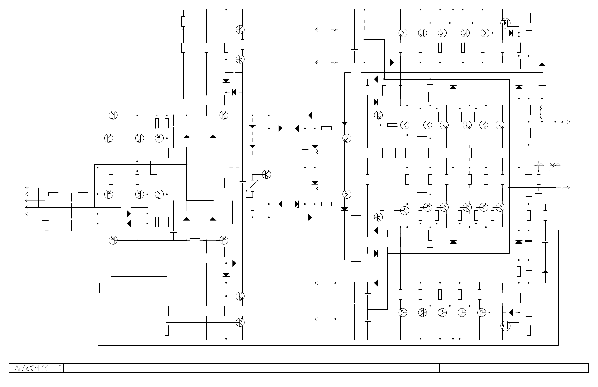
Woofer amplifier board.
One of these is used in the 3000 model,
and two are used in the 1800.
Q11
2N5551
Q8
K1-1,2
K1-3,4
K1-5,6
K1-7,8
K1-9,10
NC
R103
1k
C31
+
T10uF/25V
T10uF/25V
R4
1k
BC550
R9
47R
R17
C1
+
C2
680pF
C4
680pF
R104
R7
1k
1k
47R
R6
33k/0.6W
Q1
BC560
BAV20
BAV20
2N5401
D37
D38
Q3
BC550
BC560
R8
33k
Q9
R10
47R
R16
47R
Q2
R15
390R
Q10
BC560
BC550
R11
390R
Q4
R26
R28
R14
1k5
R13
1k5
1k
1k
R12
5k6
R23
1k
R25
1k
C7
100nF
100nF
C8
2k7/5W
R110
47R
R20
390R/0.6W
D5
6,2V
D6
6,2V
R21
390R/0.6W
R109
47R
R47
2k7/5W
R38
R84
560R
D12
BAV20
D4
15V
R29
3k9/0.6W
D7
15V
Q5
2N5401
D10
BAV20
R24
220R
C12
10pF
D13
BAV20
R31
5k6/0.6W
Q12
2N5551
C3
33pF
C13
100nF
R30
5k6/0.6W
D11
BAV20
C11
10pF
R83
560R
Q14
2N3904
Q13
BF872
Q6
BF871
R27
220R
Q7
2N3906
D14
1N4007
D15
1N4007
R33
1k
R85
1k
R32
1k
BAV20
Q15
BC550
BAV20
D28
D26
+80V (red)
+40V (white)
D29
3V
C26
10uF/35V
C27
10uF/35V
D27
3V
C36
100nF
- 40V (light blue)
- 80V (yellow)
K2-1
K2-2
D39
1N4007
+
+
D40
1N4007
K2-4
K2-5
LED
D8
D9
LED
R107
3k3
R108
3k3
P1
100uF/63V
P2
Q16
2N5551
2N5401
Q17
D25
BAV20
P3
P4
C9
C10
100uF/63V
R34
1k5
R100
10R
D24
BAV20
R99
10R
R35
1k5
+
+
R76
150k
R73
560R
R86
560R
R78
150k
C23
4,7uF/100V
C22
4,7uF/100V
D33
BAV20
D34
BAV20
D32
BAV20
D31
BAV20
D36
BYV79
C25
4,7uF/100V
C24
4,7uF/100V
2SC5200
Q18
MJE15030
2R2/0.6W
R81
47R/ 0.6W
2R2/0.6W
Q19
MJE15031
Q32
D35
BYV79
R75
330k
R87
R88
R77
330k
2SC5200
R101
6R8/2W
Q21
2SA1943
R46
2SC5200
R36
0R1/5W
P1
F 20A
Q20
R57
R63
P2
F 20A
0R1/5W
Q37
2SA1943
Q33
2SC5200
22R/2W
22R/2W
2SA1943
2R2/2W
R91
Q23
R71
1k
R72
1k
R89
R105
C32
220nF
R48
2SA1943
2SC5200
R37
0R1/5W
2R2/2W
R58
R64
Q28
2R2/2W
0R1/5W
Q38
Q34
C33
220nF
R106
2R2/2W
R90
Q22
2SC5200
R22/5W
R22/5W
2SA1943
R95
R51
R39
0R1/5W
2R2/2W
R56
R74
Q27
2R2/2W
0R1/5W
Q39
2SA1943
R22/5W
R22/5W
2SC5200
D22
BY399
R92
Q24
2SC5200
Q29
2SA1943
R96
D23
BY399
R53
Q40
2SA1943
Q35
R42
0R1/5W
2R2/2W
R59
R65
2R2/2W
0R1/5W
R93
Q25
2SC5200
R22/5W
R22/5W
Q30
2SA1943
R97
R55
2SA1943
2SC5200
0R1/5W
2R2/2W
R60
R66
2R2/2W
0R1/5W
Q41
Q36
R43
R94
Q26
2SC5200
R22/5W
R22/5W
2SA1943
R98
2R2/2W
Q31
2R2/2W
R61
R67
R50
Q43
D17
12V
R40
2R2/2W
R44
1k2/2W
D21
12V
R22/5W
R22/5W
R49
1k2/2W
2R2/2W
D19
12V
IRF9540
IRF540
R52
Q44
R41
100R
C29
C30
D20
12V
R68
2R2/5W
100uF/16V
+
100uF/16V
100R
R45
47R
C17
680pF
C16
1n2
C14
100nF
R70
10k
+
R69
MBS4992
C28
220nF
R102
2R2/2W
+
C19
100uF/16V
C20
1n2
C21
680pF
R54
47R
BAV20
+
C15
100uF/16V
L1
3uH
10R
TR2
R82
150k
D16
R62
2R2/2W
C18
100nF
D18
BAV20
OUTPUT
P6
(grey) OUT
TR1
BT139
P5
K2-3
(green) GND
K2-6
Amplifier
©2000 All rights reserved, Mackie Designs Inc.FUSSION Service Manual
Woofer amplifier board MN 042 101 Rev 02
MN 042 101 Rev 02
26.4.2000
2
Page 3

21
grey
yellow
14
15 16
17
2X
12
2X
13
14 15 16
17
red
green
white
blue
22X
red
P1
+
F1
+
3
6X
29
yellow
1
J1
P2
J2
GA1A2
P6
1
green
P5
white
P3
+
J3
+
+
grey
blue
P4
F2
+
19
31
6X
6 7
Component side
Wire from connector position 21 is soldered on solder side.
8
9
23
5
4X
©2000 All rights reserved, Mackie Designs Inc.FUSSION Service Manual
Woofer amplifier board MN 042 101 Rev 02
3
Page 4
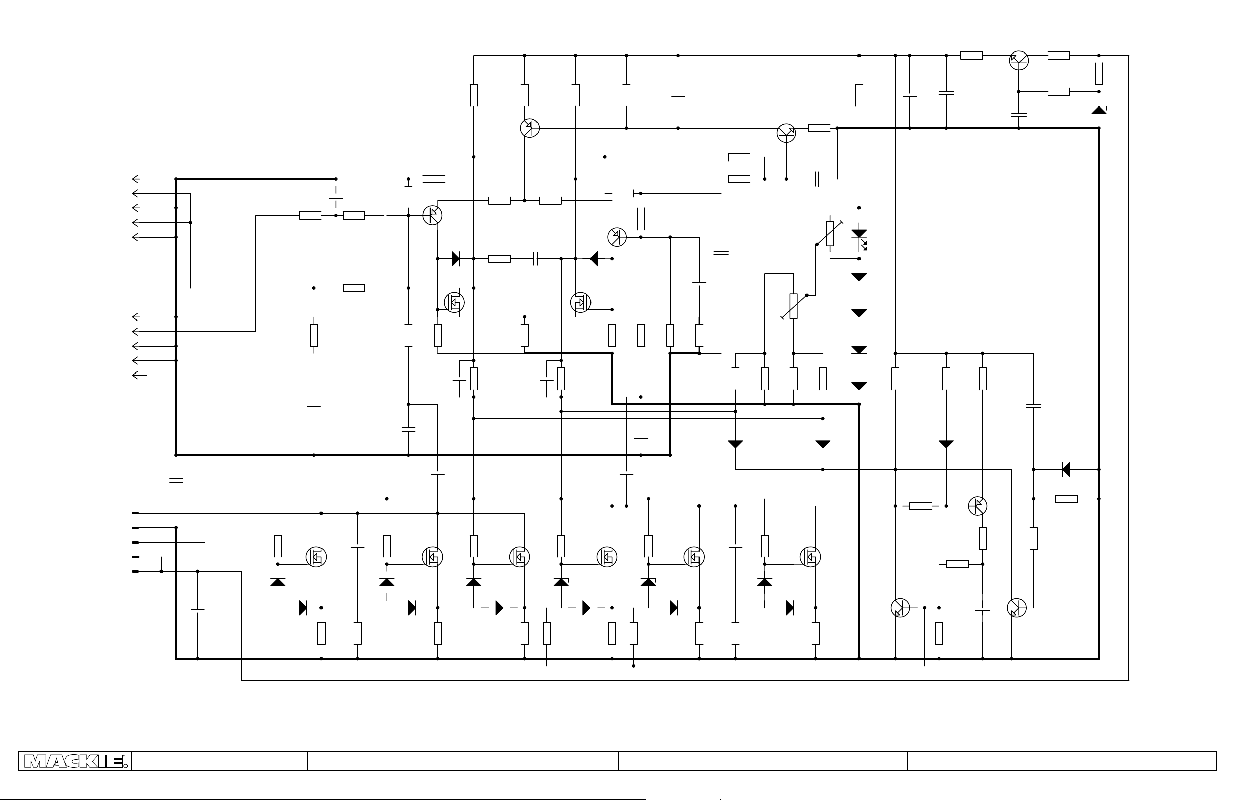
Midrange amplifier board
One of these is used in the 3000 model.
K1
K1-9
K1-7
K1-5
TR feedback K1-3
TR feedback K1-1
K2
GND K2-9
signal IN K2-7
GND K2-5
GND K2-3
K3
K3-5
K3-4
K3-3
K3-2
K3-1
No
connect
C2
100nF
C21
4.7uF/100V
R64
68R
D26
ZD12V
IRFP 240
K2-1
TR OUT 1
GND
TR OUT 2
TR OUT cen.
+ 45V
R3
560R
T17
D27
ZD12V
R62
R33/5W
C23
680pF
22R/2W
C5
47nF
R7
100nF
C6
R4
1k5
R1
100k
T4.7uF/25V
T4.7uF/25V
R52
68R
D24
ZD12V
R50
6R8/2W
C7
C1
47pF
C3
+
+
10k
R2
IRFP 240
D25
ZD12V
R33/5W
R5
10k
C4
10pF
T12
R51
220R/0.6W
R8
10k
BC557
T2
BS170
R6
1k
C11
1uF
R12
T1
D1
BAV20
R53
68R
D22
ZD12V
R24
100k
220R
BC557
R13
100R
R35
220R
T13
IRFP 240
D23
ZD12V
R33/5W
R26
T6
R54
C10
1uF
220R/0.6W
100R
C25
1.2nF
R9
22R
D20
ZD12V
R18
R56
68R
R11
R32
1k5
R21
100k
BC557
D2
BAV20
BS170
T14
IRFP 240
D21
ZD12V
R33/5W
T3
R55
R47
2R2/0.6W
+
C17
220uF/25V
R41
560R
D14
BAV20
R43
4k7
C15
22uF/50V
R34
680
220uF/25V
R19
6k8
+
IRFP 240
R33/5W
R63
R27
22k
R61
10k
D3
BAV20
T16
R31
2k2
D9
LED
D5
1N4007
D6
1N4007
D7
1N4007
D8
1N4007
T9
BC550
R25
2k2
R20
10k
T4
R10
1k
ZD12V
D18
R57
68R
C16
10pF
R33
1k5
100nF
R16
10k
R17
10k
C12
47pF
C13
100nF
R14
100k
IRFP 240
D19
ZD12V
C9
T15
R15
1k5
C20
100nF
R58
R33/5W
R22
22k
R23
22k
+
C8
T4.7uF/25V
R29
22k
D28
ZD12V
6R8/2W
D50
BAV20
R59
R30
22k
R65
68R
R60
10k
T5
BC550
D29
ZD12V
C22
22uF/50V
R28
22k
R42
22k
C14
100nF
R39
2k2
C18
R40
560R
T8
BC557
R38
3k3
+
T11
BD139
+
T10
BC550
47R/2W
+
C19
22uF/50V
R44
22k
R49
R46
100R
D16
BAV20
R45
100k
R48
2k2/0.6W
D17
ZD15V
©2000 All rights reserved, Mackie Designs Inc.FUSSION Service Manual
Midrange amplifier board MN 042 109 Rev 02
4
Page 5

G
S
T12
1
2
3
4
5
G
S
T13
G
S
T17
G
S
T16
G
S
T14
G
S
T15
E
R61
R60
3X
10
6X
9
11 12
3X
6X
13
3
6X
27
8X
4 5
6
2X2X2X
T12
G
C5
R7
T1
J1
J2
C2 C4
R1
C3
R2
R3
R5
+
C7
R4
C23
S
D25
D24
E
B
C
C1
D1
+
C25
DG S
R6
T2
R35
R8
R9
DG S
R12
T3
R11
R13
R10
R52
C12
R53
C10
R15
G
T13
D22
R14
D23
C8
R26
R19
CB E
R25
+
C22
G
C13
T6
CB E
T5
T17
R64
R28
D26
S
D27
R60
R61
R54R51
S
C11
R24
R23
R22
R21
D2
R20
+
T4
CB E
C9
R16
R17
R18
K
R27
D8
D3
D6
D7
K
K
002
1
D5
K
R29
C14
D9
R30
T16
G
R31
R34
001
R32
R38
S
R65
C15
D28
R43
R63R62
D29
C
BE
CB E
R39
T9
T8
C16
R33
D14
T14
G
D21
D20
R56
(+)
C17
R41
D16
R45
R57
T10
C
BE
+
R40
D50
C19
S
R44
D18
C18
R42
R47
D19
(+)
R46
T11
D17
E
G
R48
T15
C20
R49
C6
R58R55
S
5
R59
R50
4
24
23
3
C21
J3
2
1
5X
29
17
18 19 20 21
©2000 All rights reserved, Mackie Designs Inc.FUSSION Service Manual
Midrange amplifier board MN 042 109 Rev 02
5
Page 6

High Frequency amplifier board
One of these is used in the 3000 model.
K1
K1-9
K1-7
K1-5
TR feedback K1-3
TR feedback K1-1
K2
GND K2-9
signal IN K2-7
GND K2-5
GND K2-3
K3
K3-5
K3-4
K3-3
K3-2
K3-1
No
connect
C2
100nF
C21
4.7uF/100V
K2-1
TR OUT 1
GND
TR OUT 2
TR OUT cen.
+ 45V
680pF
R3
560R
C23
R7
6R8/2W
C5
47nF
100nF
C6
R4
1k5
R1
100k
T4.7uF/25V
T4.7uF/25V
R52
68R
D24
ZD12V
R50
6R8/2W
C7
C1
+
+
10k
C3
47pF
R2
IRFP 240
D25
ZD12V
R33/5W
R5
10k
C4
10pF
T12
R51
220R/0.6W
R8
10k
BC557
T2
BS170
R6
1k
C11
1uF
R12
T1
D1
BAV20
R53
68R
D22
ZD12V
R24
100k
R26
220R
BC557
R13
100R
R35
220R
T13
IRFP 240
D23
ZD12V
R33/5W
T6
R54
C10
1uF
220R/0.6W
100R
C25
1.2nF
R9
22R
D20
ZD12V
R18
R56
68R
R11
R32
1k5
R21
100k
BC557
D2
BAV20
BS170
T14
IRFP 240
D21
ZD12V
R55
R33/5W
R47
2R2/0.6W
+
C17
220uF/25V
R41
560R
D14
BAV20
R43
4k7
C15
22uF/50V
R34
680
220uF/25V
R19
6k8
+
R61
10k
R27
22k
BAV20
D3
R31
2k2
D9
LED
D5
1N4007
D6
1N4007
D7
1N4007
D8
1N4007
T9
BC550
R25
2k2
R20
10k
T4
T3
R10
1k
ZD12V
D18
R57
68R
C16
10pF
R33
1k5
C13
100nF
R16
10k
R17
10k
C12
47pF
100nF
R14
100k
T15
IRFP 240
D19
ZD12V
C9
R15
1k5
C20
100nF
R58
R33/5W
R22
22k
R23
22k
+
C8
T4.7uF/25V
R29
22k
6R8/2W
D50
BAV20
R59
R30
22k
T5
BC550
R60
10k
C22
22uF/50V
R28
22k
R42
22k
C14
100nF
R39
2k2
C18
R40
560R
T8
BC557
R38
3k3
+
T11
BD139
+
T10
BC550
47R/2W
+
C19
22uF/50V
R44
22k
R49
R46
100R
D16
BAV20
R45
100k
R48
2k2/0.6W
D17
ZD15V
©2000 All rights reserved, Mackie Designs Inc.FUSSION Service Manual
High Freq amplifier board MN 042 110 Rev 02
6
Page 7

G
S
T12
1
2
3
4
5
G
S
T13
G
S
T14
G
S
T15
E
R61
R60
6X
9
3
11 121013
4X
2X
15 12 13
4X
27
8X
4 5
2X
T12
G
C5
R7
T1
J1
J2
C2 C4
R1
C3
R5
R2
+
C7
R4
R3
C23
S
D25
D24
E
B
C
C1
D1
+
C25
DG S
R6
T2
R35
R8
R9
DG S
R12
T3
R11
R13
R10
R52
C12
R53
C10
R15
G
T13
D22
R14
D23
C8
R56
R41
D20
R45
G
D21
D16
T14
R57
T10
C
BE
+
R40
D50
C19
S
R44
D18
C18
R42
R47
D19
(+)
D6
R60
R61
K
R27
D8
D3
D7
D5
K
K
K
R32
R31
002
R29
D9
R30
C14
R34
001
R38
R43
C15
T9
C
BE
T8
CB E
R39
C16
R33
(+)
C17
D14
R54R51
S
C11
R26
R25
R24
R19
CB E
CB E
+
C22
C13
T6
T5
R28
R23
R22
R21
D2
R20
+
T4
CB E
C9
R16
R17
R18
R46
T11
D17
E
G
R48
T15
C20
R49
C6
R58R55
S
5
R59
R50
4
24
23
3
C21
J3
2
1
5X
29
1
17
18 19 20 21
©2000 All rights reserved, Mackie Designs Inc.FUSSION Service Manual
High Freq amplifier board MN 042 110 Rev 02
7
Page 8

K2-3 OUT / PHASE (B I/O)
K2-9 LEVEL (B I/O)
K5-3 LMID OUT (PA 1500)
K2-5
K6-3 MID OUT (TR 300)
K2-1 OUT / PHASE (B I/O)
U6
U9U3U1
U8
U2
U7U5
U10 U11 U14
U15
U18
U19
K4-3 HI OUT (TR 100)
K4-1
K4-5
K4-7
K4-9
K5-1
K5-5
K5-7
K5-9
K6-1
K6-5
K6-7
K6-9
IN +40V K7-1
K7-3
K7-5
K7-7
IN -40V K7-9
INPUT
GND K1-7
GND K1-1
POSITIVE IN K1-3
NEGATIVE IN K1-5
K1-9
2
3
3
2
5
6
6
5
3
2
3
2
5
6
5
6
3
2
5
6
6
5
2
3
6
5
6
5
2
3
5
6
6
5
2
3
5
6
3
2
2
3
3
2
5
6
3
2
2
3
2
3
6
5
1
1
1
1
1 1
1
1
7
1
1
11
1
1
7
7
7
77
7
7
7
7
7
7
7
K3-1
K3-3 SUB OUT POSITIVE
K3-7
K3-9 I/O BOARD
K3-5 SUB OUT NEGATIVE
MN 044 501
K2-7 LEVEL (B I/O)
FILL OUT
29.2.2000
Rev 01
+15V
-15V
-15V
+15V
+
4
8
NE5532
D4
BAV20
+
C67
220uF/25V
R123
3k9
R152
47k
+
C86
100uF/25V
R168
4k7
+
C85
220uF/25V
D20
LED
+
C68
220uF/25V
C21
220nF
C50
680pF
+
C4
T10uF/25V
+
C87
100uF/25V
+
C3
1uF
+
C84
220uF/25V
C66
100nF
R59
47k
R147
10k/0.6W
R1
47k
R156
10k
+
C75
T10uF/25V
K5
C47
100nF
R166
100R
R110
82k
C78
10pF
C52
1uF
MUTE
R177
1M
R121
2k7
+
-
U8A
NE5532
T10
BC550
R19
47k
OPT1
WK 163 41
R18
1M
R124
10k/0.6W
R14
47k
R149
560R
MUTE
R145
1k/0.6W
D7
BAV20
T2
TIP 126
R69
10k
R104
1k/0.6W
D1
BAV20
R165
2k2
R37
100R
C8
100nF
R105
10k/0.6W
R45
47k
R27
10k
R60
10k
+
-
U3B
NE5532
T15
J107
R46
10k
R5
1M
+
-
U11B
NE5532
R48
47k
R148
33k
R20
47k
C54
100nF
T6
BC550
+
C10
220uF/25V
K1
R176
10k
+
-
U7A
NE5532
C51
1uF
R97
2k2
K7
T3
BC550
K3
R62
15k
R3
47k
C71
100nF
R179
100R/5W
C25
47nF
R8
2k2
MUTE
C28
1uF
C46
22nF
R174
100R
C7
1uF
R42
100R
R151
10k
R171
10k
+
-
U19A
NE5532
C22
100nF
T11
J107
R158
10k
R86
2k2
+
4
8
NE5532
+
-
U2B
NE5532
D16
BAV20
C36
100nF
T14
J107
MUTE
D13
BAV20
C19
220nF
C82
100nF
R109
560R
D9
BAV20
R169
2k2
R7
47K
+
4
8
NE5532
R99
2k2
C74
47nF
+
-
U6B
NE5532
+
4
8
NE5532
+
-
U14B
NE5532
+
4
8
NE5532
R181
10k
R25
1M
+
-
U10A
NE5532
D6
BAV20
D17
ZD16V
C57
22nF
C23
22nF
R40
100R
R111
560R
R89
100k
+
4
8
NE5532
D21
BAV20
T4
2N5401
+
C12
T10uF/25V
K4
C72
47nF
+
-
U18B
NE5532
R159
10k
+
4
8
NE5532
D8
BAV20
D15
BAV20
C38
22nF
R173
100R
T12
J107
C44
1uF
R76
1k8
C79
100nF
R163
4k7
R114
8k2
R2
47K
R71
47k
R93
1k
+
4
8
NE5532
R50
560R
C31
47nF
R74
15k
R41
330R
K9
+
-
U5A
NE5532
R66
270R
R67
2k2
R32
6k8
T1
TIP 121
R167
2R2/0.6W
C69
22nF
+
C11
220uF/25V
+
-
U1A
NE5532
R170
100R
R120
1k8
R39
330R
D12
BAV20
R140
1k5
+
-
NE5532
U18A
+
4
8
NE5532
C42
47pF
R102
2k2
R161
47k
+
-
U15B
NE5532
C89
100nF
+
-
U7B
NE5532
R28
560R
+
-
U6A
NE5532
+
4
8
NE5532
R9
47k
R21
2k2
+
4
8
NE5532
R107
100k
R157
10k
+
4
8
NE5532
C48
22nF
+
-
U3A
NE5532
C80
100nF
R160
10k
T9
BC550
C78A
47pF
C26
220nF
+
C5
T10uF/25V
D14
BAV20
C15
T10uF/25V
R52
47k
R61
560R
R164
2R2/0.6W
R24
1M
R23
1M
T5
BC550
R36
2k2
R44
47k
C24
100nF
R92
8k2
MUTE
+
-
U9B
NE5532
R65
10k
R73
22k
R108
22k
C37
22nF
R16
3k9
R180
4k7
R6
1M
+
-
U9A
NE5532
C81
100nF
T8
BC550
R26
10k
MUTE
D2
BAV20
R154
1k
+
C76
T10uF/25V
R153
47k
C13
220nF
+
-
U5B
NE5532
R150
4k7
R155
10k
K2
D3
BAV20
R130
560R
R4
2k2
C73
47nF
C56
22nF
+
-
U10B
NE5532
C45
47nF
C16
T10uF/25V
R172
10k
R68
10k
R15
560R
R70
10k
+
-
U14A
NE5532
R116
1k8
R35
2k2
C72A
47nF
+
-
U11A
NE5532
D5
BAV20
+
-
U8B
NE5532
R47
10k
R75
2k2
C65
680pF
D22
BAV20
R10
47k
C49
22nF
D23
BAV20
T13
J107
R125
10k
C35
100nF
+
-
U15A
NE5532
R38
2k2
R98
2k2
T7
BC557 C
+
C2
T10uF/25V
R43
560R
+
-
U2A
NE5532
D11
BAV20
C77
100nF
R106
22k
+
4
8
NE5532
R178
100R/5W
R90
100k
R118
1k8
R94
1k8
R103
1k8
K6
R115
3k3
C34
22nF
+
C1
T10uF/25V
R72
39k
C43
1uF
R49
12k
R87
560R
R101
2k2
C64
10pF
R22
1M
C70
220nF
+
-
U1B
NE5532
+
4
8
NE5532
D10
BAV20
C83
220pF
R146
10k/0.6W
R17
1M
Control board
One of these is used in the 3000
©2000 All rights reserved, Mackie Designs Inc.FUSSION Service Manual
Control board MN 044 501 Rev 01
8
Page 9

©2000 All rights reserved, Mackie Designs Inc.FUSSION Service Manual
Control board MN 044 501 Rev 02
9
Page 10

Capacitor board
One of these is used in the 3000 model.
P1,P2
P3,P4
P9,P10
P5,P6
P7,P8
C1
+
+ C4
+C5
+ C8
C6
K3-1
K3-3,5,7
K3-9
K1-1
+C2
K1-2
+C3
K1-3
+
P11-P13
K1-4
+C7
K1-5
ITEM QTY UNIT DESCRIPTION RM NO.
1
1
2
8
3
0,006
4
0,27
5
6
6
7
1
8
9
2
10
1
11
1
12
13
14
0,02
15
1
16
NOTE:
1. Capacitors C1-C8: before placing on board spread by item 4. After soldering, glue together all capacitors with item 5.
2. Assembling conectors K1 and K2: see below.
3. Connect K1/3 to K2/2 by solder, item 15 see detail A.
4. Write serial number on item 16.
PCB ZD 1500
ks
C1 - C8 capacitor electolytic 10mF/50V size 30x45 10
ks
silicon glue LOCTITE
kg
polyethylen glue
m
K1 - faston blade to PCB male 6,3 x 0,8 CT 100 ENIKA 5,08
ks
case
ks
K2 - faston blade to PCB male 6,3 x 0,8 CT 100 ENIKA 5,08
ks
case
ks
K3 - connector 10 pins (2x5pins)
ks
solder
kg
serial number plate
ks
MB 049 002
P1
P2
P3
P4
(+)
C1
K1-6
K2-1
K2-2
1
(+)
C2
5 43 16
(+) (+)
C3
C4
K1
DETAIL - A
View from solder side
solder together, item 15
A
78
1
1
P10
P9
P11
P12
K3
P13
1
K2
10
(+)
11
C5
(+)
View from component side
C6
C7 C8
(+)
(+)
P7
P8
P6
P5
Assembly of connector K1
8
©2000 All rights reserved, Mackie Designs Inc.FUSSION Service Manual
Assembly of connector K2
7
11
10
Board ZD 1500B
MN 051 402 Rev 03
3000 Capacitor board ZD 1500B MN 051 402 Rev 03
8.3.2000
10
Page 11

Capacitor board
Two of these are used in the 1800 model.
P1,P2
P3,P4
P9,P10
P5,P6
P7,P8
C1
C3
C5
C7
+
+ C4
+
+
ITEM QTY UNIT DESCRIPTION RM NO.
1
8
0,006
0,27
6
1
2
1
0,02
1
pc
C1 - C8 capacitor elecrolytic 10mF/50V size 30x45 10
pc
silicon glue LOCTITE
kg
polyethylen glue
m
K1 - faston blade to PCB male 6,3 x 0,8 CT 100 ENIKA 5,08
pc
case
pc
K2 - faston blade to PCB male 6,3 x 0,8 CT 100 ENIKA 5,08
pc
case
pc
solder
kg
serial number plate
pc
1
K1-1
+C2
K1-2
+
K1-3
+
C6
C8
+
P11-P13
K1-4
K1-5
K1-6
K2-1
K2-2
2
3
4
5
6
7
8
9
10
11
12
13
14
15
16
NOTE:
1. Capacitors C1-C8: before placing on board spread by item 5. After soldering, glue together all capacitors, item 4.
2. Assembling conectors K1 and K2: see below.
3. Connect K2/1 to K2/2 by solder, item 15.
4. Write serial number on item 16.
PCB ZD 1500
MB 049 002
P1
P2
(+)
C1
P3
P4
Assembly of connector K1
8
1
(+)
C2
(+) (+)
C3
C4
5 43 16
Assembly of connector K2
7
11
K1
78
K2
10
11
P7
P8
1
P10
P12
P11
P9
P13
1
(+)
C5
C6
(+)
C7 C8
(+)
(+)
P6
P5
10
Board ZD 1500A
MN 051 401 Rev 03
8.3.2000
©2000 All rights reserved, Mackie Designs Inc.FUSSION Service Manual
1800 Capacitor board ZD 1500A MN 051 401 Rev 03
11
Page 12

B3 +
One of these is used in the 3000 model
B3 -
TR3/6
TR3/8
TR2/1
TR2/4
P19
P18
P17
P16
P21
P20
ITEM
QTY
UNIT
DESCRIPTION RM
1
1
10
11
12
13
14
15
16
17
18
19
20
21
2
4
3
0,003
4
0,2
5
6
4
7
1
8
4
9
1
1
1
1
1
0,28
0,28
0,425
1
0,02
1
P15
F1
FUSE 10A
F2
C2
C1
+
+
C3
+
C4
+
FUSE 20A
K1-1
K1-2
K1-3
K1-4
P14
P13
P10
P11
P12
P9
T100W /K3 (1)
T300W /K3 (1)
CB4W /K9
T100W /K3 (4)
T300W /K3 (4)
PCB ZD FET
pc
C1 - C4 capacitor electrolytic 10mF/50V size 30x45 10
pc
silicone glue LOCTITE
kg
polyethylen glue
m
K1 - faston blade to PCB male 6,3 x 0,8 CT 100 ENIKA 5,08
pc
case
pc
holder fuse to PCB CT 136 ENIKA 5,08
pc
F1 - fuse 10A F size 6,3 x 32
pc
F2 - fuse 20A F size 6,3 x 32
pc
Cable I. for ZD FET
pc
Cable II. for ZD FET
pc
Cable III. for ZD FET
pc
stranded wire CYA 1,5 yellow
m
stranded wire CYA 1,5 white
m
stranded wire CYA 1,5 green
m
connector faston female flag 6,3x0,8 90˚ FTM 6,3L ENIKA
pc
solder
kg
serial number plate
pc
TESLA NO.
MB 049 001
MA 251 402
MK 650 102
MK 650 103
MK 650 104
0
14
13
white
green
yellow
brovn
19
21
4
1
5
4X
NOTE:
1. Capacitors C1-C4: before placing on board, spread by item 4. After soldering, glue together
all capacitors using item 5.
2. Assembling connectors K1: see below.
3. Write serial number on item 21.
9
4X
TR3/1
TR3/4
TR3/3
red
green
18
TR2/6
TR2/8
white
green
yellow
brovn
red
P10
TR2/7
P15
P9
F1
F2
P14
P13
P12
P11
17
16
(+)
(+)
P17
P16
C2
C1
1
K1
P20
P21
C3
C4
(+)
(+)
P19P18
17
16
length 0,14 m
length 0,14 m
brown
black
15
Assembly of connector K1
8
1
4X
length 0,14 m
length 0,14 m
TR3/8
TR3/6
TR2/1
TR2/4
©2000 All rights reserved, Mackie Designs Inc.FUSSION Service Manual
5
ZD FET Board
MN 051 403 Rev 03
Capacitor board ZD FET MN 051 403 Rev 03
18.4.2000
12
Page 13
ITEM QTY UNIT DESCRIPTION RM NO.
GND
1
1
1
K1
K2
K3
1
1
1
1
K4
K6
K7
K8
K5
D1
R1
S1
S2
ITEM QTY UNIT DESCRIPTION RM NO.
1
2
3
4
5
6
7
8
9
10
pc
pc
pc
pc
pc
pc
g
m
PCB
K1, K2 - connector 10 pins (2 x5 pins)
K3 - connector XLR NC3FAV20 NEUTRIK
K4 - connector XLR NC3MAV2 NEUTRIK
K5, K6 - faston blade for PCB male 6,3 x 0,8 CC342 ENIKA 5,08
serial number plate
solder wire
wire Cu Sn 0,63
MB 049 2031
2
1
1
2
1
0,01
NOTE:
1. Write serial number on item 6, the location is on the solder side.
2. Solder components to board after setting all component on panels PWR 1800 ( MF 149 002 or MF 149 004 ).
3. Connect K5 to K6 by item 9 from soldering side.
GNDGND
1
1
15.17.1999
11
11
6
5
1
2
4
3
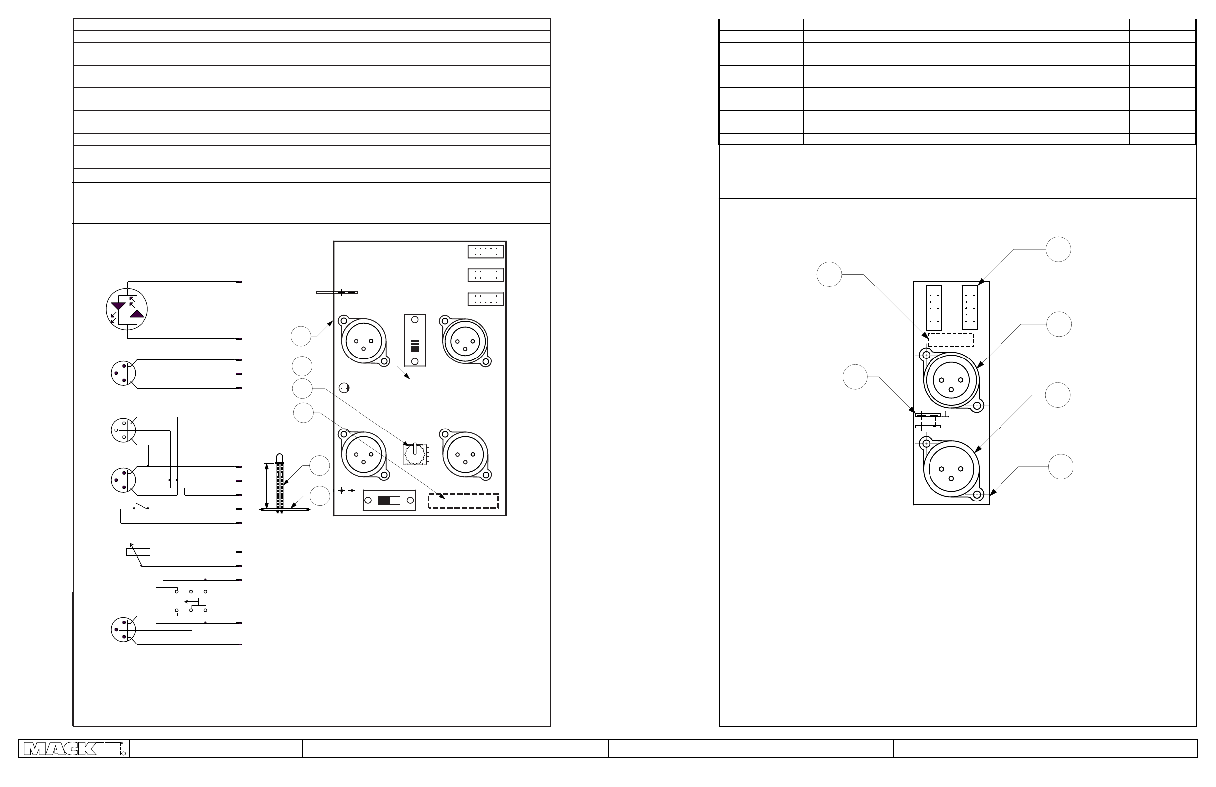
INPUT AND OUTPUT BOARD
MN 052 103 Rev 01
K5
K6
K3
K4
K1 K2
2X
2X
View from component side.
1
2
3
4
5
6
7
8
9
10
11
12
13
NOTE:
1. Write serial number on item 6. Serial number location is on the solder side.
2. Soldering component to board have to be after set all component on panels PWR 3000 ( MF 149 001 or MF 149 003).
1
3
1
3
1
1
1
1
2
0,046
1
0,008
0,012
PCB
pc
K1 - K3 connector 10 pins (2 x 5 pins)
pc
K4 - connector XLR NC3FAV20 NEUTRIK
pc
K5 - K7 connector XLR NC3MAV2 NEUTRIK
pc
K8 - faston blade for PCB male 6,3 x 0,8 90˚ CT 103 ENIKA 5,08
pc
R1 - potentiometer 9mm shaft 25mm 50k/N D8c503 ALPS
pc
knob dark grey 760-048-04 MACKIE
pc
D1 - diode LED dual led (red/green) 3mm L-937EGW
pc
S1, S2 - switch slide DPDT mini SLSW2P2T
pc
izol. tube silicone 1x1 black
m
serial number plate
pc
solder wire
kg
wire Cu Sn 0,63 10,16
m
View from component side.
RED
K6
K4
K5
1
2
1
3
2
2
3
1
1
3
2
S1
D1
conv33
GREEN
K3-9
K3-7
K3-1
K3-5
K3-3
K1-1
K1-3
K1-5
K1-7
K1-9
Assembly of diode D1
23
1
13
7
11
K8
GND
K5
1
D1
K7
1
S1
R1
10
2X
1
S2
MB 049 202
K3
K1
K2
1
1
1
1
K4
1
K6
R1
K7
K2-9
K2-7
K2-3
conv25
2
3
1
S2
K2-1
K2-5
Input/output for 3000
Input/Output board
MN 052 102 Rev 02
©2000 All rights reserved, Mackie Designs Inc.FUSSION Service Manual
Input/output for 1800
I/O boards MN 052 102 and MN 052 103
13
Page 14

ITEM QTY QTY UNIT DESCRIPTION RM TESLA NO.
1
2
3
4
5
6
7
8
9
10
1
2
0,09
0,09
0,12
0,12
-
0,1
0,03
0,03
1
0,2
0,2
0,01
0,01
1
1
2
1
1
8
1
1
MN 052 105
1
pc
2
pc
m
m
g
m
1
pc
g
m
1
pc
1
pc
2
pc
1
pc
1
pc
1
pc
8
pc
1
pc
1
pc
MN 052 106
eyelet 4x1,5 7610-03/4
stranded wire LaU 0,15 white
stranded wire LaU 0,15 black
coupler tin coated copper wire 0,63 x 15 mm 6,35
izol. tube SD 48F black
serial number plate
solder
polyethylen glue
R1 - resistor carbon film 10K/J 0,25W size 0207 12,7
R2 - resistor metal film 3K3J 0,6W size 0207 12,7
R3, R4 resistor carbon film 100R/J 0,25W size 0207 12,7
C1 - capacitor film 100nF 250V AC CFAC100N GM 15,24
C2 - capacitor electrolytic 1000uF 16V size 10 x 16 5,08
D1 - diode 1000V/1A 1N4007 12,7
J1 - J8 faston blade to PCB male 6,3 x 0,8 CC342 ENIKA 5,08
J9 - connector HDR 2P.098 X1
J10 faston blade to PCB male 6,3 x 0,8 CC342 ENIKA 5,08
NOTE:
1. the ends Items 4 and 5: strip the wires 5mm, solder
2. wires turns (6 turns)
3. Fix the capacitor C1 and C2 by item 10.
MB 049 010PCB Start Up Module
3
7
45
610
8
(+)
One of these is used in the 1800 model. One of these is used in the 3000 model.
1
Start Up Module
MN 052 105,106
©2000 All rights reserved, Mackie Designs Inc.FUSSION Service Manual
Rev 04
8.3.2000
Startup Modules MN 052 105, 106
14
 Loading...