

Mackie 56-input, 72 channel, fully automated digital audio mixing console, Digital 8-Bus Quick Start Manual
Page 1
DIGITAL 8•BUS
QUICK START GUIDE
™
MACKIE’S 56-INPUT, 72-CHANNEL, FULLY AUTOMATED DIGITAL AUDIO MIXING CONSOLE
Page 2

TABLE OF CONTENTS
1. Introduction............................................................................................................. 3
About the Quick Start Guide ......................................................................................................3
Unpacking...............................................................................................................................3
2. The Basics ...............................................................................................................5
The T raditional Split-Console Appr oach........................................................................................5
Three Things to Keep in Mind..............................................................................................5
T racking...........................................................................................................................5
Monitoring .......................................................................................................................6
Overdubbing/Bouncing T racks.............................................................................................6
Mixdown.........................................................................................................................7
Signal-flow Diagram ................................................................................................................7
3. Tutorial Hookup — Let’s Get It Working! .................................................................. 8
Hookup Stuff ..........................................................................................................................8
Power-Up...............................................................................................................................9
Start-up .............................................................................................................................10
System Options ..............................................................................................................10
Downloading Plug-Ins...................................................................................................... 10
Getting Sound Out .................................................................................................................11
Preparing to Record ...............................................................................................................11
Saving Y our Session...............................................................................................................14
Creating a Default Snapshot ....................................................................................................14
4. General Guidelines.................................................................................................15
Three Things to Keep in Mind (Reprise) .....................................................................................15
Setting Levels .......................................................................................................................15
Input Sensitivity Adjustment Procedure for Channels 1-24 .................................................... 15
Using Internal Channel Processing and Internal Effects.................................................................16
EQ .............................................................................................................................16
Gate .............................................................................................................................17
Compressor....................................................................................................................17
Internal Effects ...............................................................................................................17
Plug-Ins ..................................................................................................................17
MFX....................................................................................................................17
IVL Vocal Studio ....................................................................................................19
IVL Vocal Studio: Harmony Example............................................................................19
Using External Effects.............................................................................................................23
Soloing .............................................................................................................................24
5. Hookup for Multitrack Recording ............................................................................26
Hookup for T racking...............................................................................................................27
Monitoring .....................................................................................................................27
Hookup for Mixdown .............................................................................................................29
6. Hookup for Live Mixing (D8•SR) ............................................................................ 30
Setting up Monitor Mixes .......................................................................................................31
7. Digital 8•Bus Overview ......................................................................................... 32
Channel Strip Description ........................................................................................................32
Master Section Description......................................................................................................32
Rear Panel Description ...........................................................................................................36
Remote CPU Description ......................................................................................................... 38
Connecting a Mouse, Keyboard, and SVGA Monitor .............................................................38
Other Connections ...........................................................................................................38
Automation ....................................................................................................................39
Remote CPU Rear Panel View .................................................................................................40
T op Panel View .....................................................................................................................41
Rear Panel View ...................................................................................................................42
Page 3
Mackie Designs Inc.
16220 Wood-Red Rd. NE • Woodinville, WA 98072 • USA
800/898-3211 • Outside the US: 425/487-4333
Fax: 425/487-4337 • www.mackie.com
email: sales@mackie.com
™
©1998 Mackie Designs Inc. All rights reserved. #820-075-00
Page 4
1. Introduction
Now you’ve done it! You’ve just invested in
the newest generation of affordable digital
mixing consoles by Mackie Designs. Whether
or not you’ve used digital mixing consoles
before, you will be pleased by the analog feel of
our Digital 8•Bus, and by how easy it is to use.
Greg Mackie has been designing and building
analog mixers for years (since the TAPCO days
of the early ’70s), and one of the prime directives for our first digital mixing console was to
make it as easy to use as an analog mixer .
The Digital 8•Bus combines the best of both
worlds, providing an intuitive control surface
for mixing the old-fashioned way — with
faders and knobs — and providing connections
for a mouse, keyboard, and video monitor for
performing computer-oriented functions such
as file maintenance and editing. Of course, you
can perform virtually all the same mixing
functions on the video monitor as you can on
the control surface, so you have the flexibility
to choose what works best for you.
About The Quick Start Guide
This Quick Start Guide is designed to help
you get going right away . Use it, along with the
Quick Start Video, to learn the basics of setting
up and using the Digital 8•Bus. But eventually
you will have to crack open the Digital 8•Bus
Owner’ s Manual to gain a
more in-depth understanding
of what the Digital 8•Bus
can do for you.
Q u i c k S t a r t G u i d e
Unpacking
Obviously, you’ve already opened the box if
you’re reading this manual. Here are some
helpful hints on unpacking:
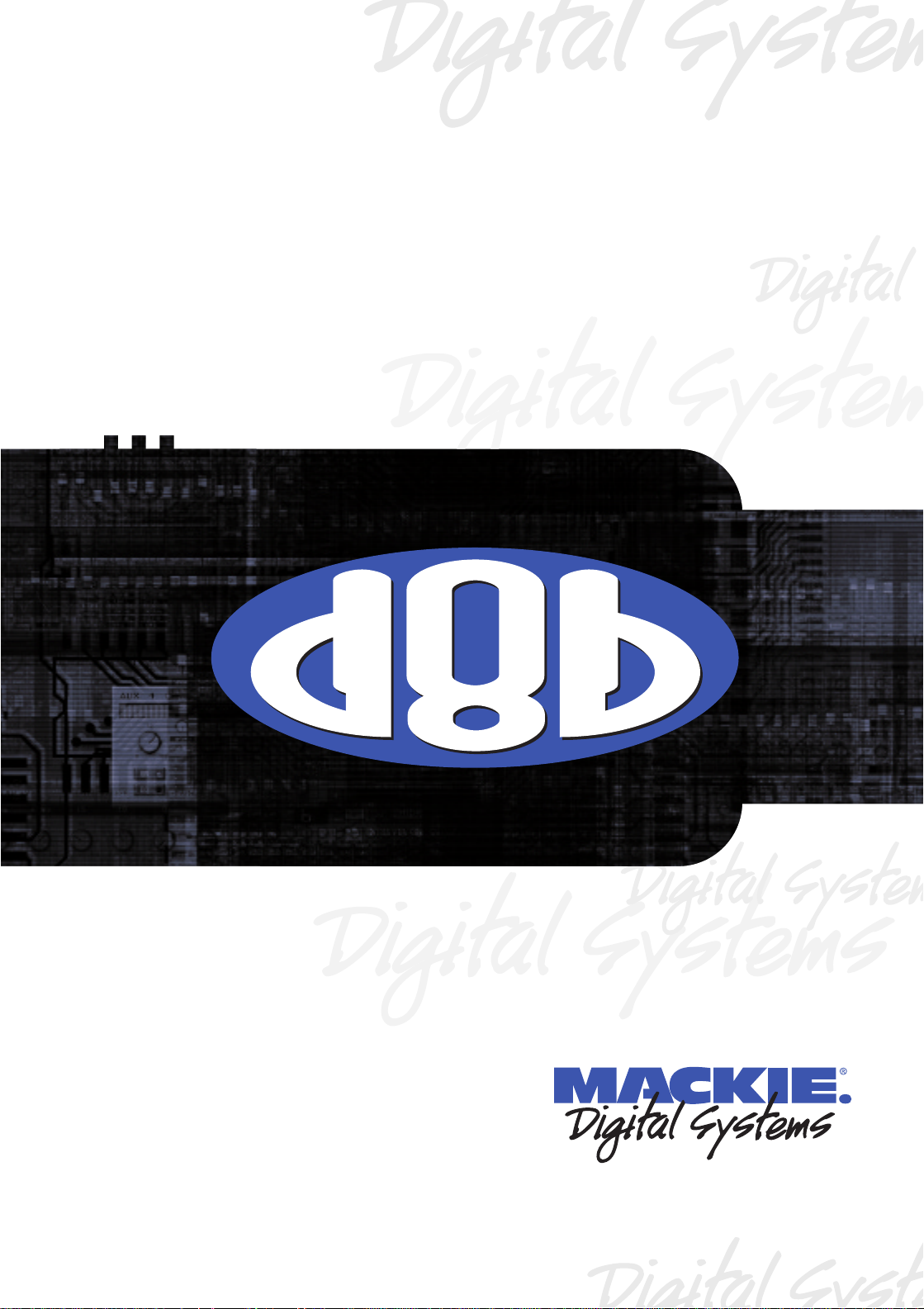
• The Digital 8•Bus comes in two parts, each
packed in a separate box: The Console and
the Remote CPU.
The Console
• If you haven’ t removed the Digital 8•Bus
from the packing box yet, remove the
accessory tray containing the manuals,
video, and miscellaneous literature.
• Remove the foam blocks from the ends of
the console. Just lift up on them and they’ll
come right out. The Digital 8•Bus weighs 65
pounds, so we recommend enlisting the help
of another person to assist in lifting it out of
the box. Position one person on each end of
the box and, on the count of three, lift the
console (remember: back straight, lift with
your legs!).
• Place the console on a flat surface, like the
floor next to the packing box, or a table top
large enough for the Digital 8•Bus to sit on.
• Remove the plastic bag from around the
console.
• Please save the box, the outer sleeve, and
all the foam innards. If you need to ship your
Digital 8•Bus anywhere, using the original
carton is the best way to do it.
box top
outer sleeve
left side
foam
factory fresh
console in
plastic bag
left side
lower foam
Figure 1. Unpacking the Console
Part No. 820-075-00 Rev. A 8/98
©1998 Mackie Designs Inc., All Rights Reserved. Printed in the U.S.A.
accessories
accessory tray
right side
foam
box bottom
right side
lower foam
Introduction
3
Page 5
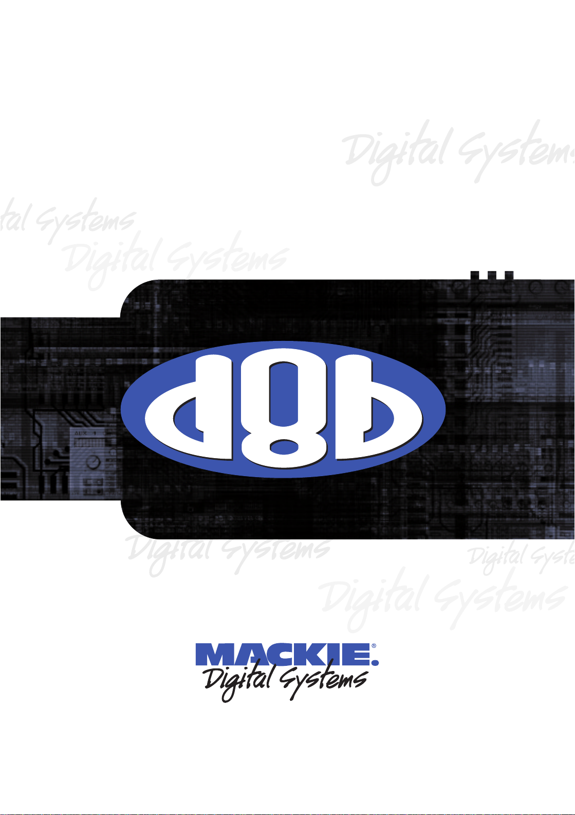
The Remote CPU
• Use a sharp knife to cut the tape on the top
of the box.
• Open the flaps to expose the Remote CPU
inside.
• Lift the Remote CPU up and out of the
packing box. The foam blocks will come
with it, and the bottom tray will lift up also.
The DC Power Cable is coiled up underneath
the bottom tray.
• Set the Remote CPU on a flat surface, like the
floor next to the packing box, or a table top.
D i g i t a l 8 • B u s
• Remove the DC Power Cable from the
bottom tray.
• Remove the foam blocks from the sides of
the Remote CPU.
• Remove the plastic bag from around the
Remote CPU, and the plastic bag from
around the DC Power Cable.
remote cpu
in plastic bag
left side
foam
connection cord
in plastic bag
Figure 2. Unpacking the Remote CPU
O
N
O
F
F
P
O
W
E
R
bottom tray
right side
foam
remote cpu
box
4
T ake a moment now to fill out the Product
Registration Card located in the back of the
Digital 8•Bus Owner’ s Manual. Mailing it in will
automatically put you on our mailing list so you
can get updated information, so do it today.
Also, write the serial numbers of your
Digital 8•Bus console and Remote CPU here
so you’ll always have them.
Console Remote CPU
Purchased at:
Date Purchased:
Introduction
Page 6
2. The Basics
The Traditional Split-Console Approach
Q u i c k S t a r t G u i d e
Before we go any farther , we want to
present a concept that might help you
understand the Digital 8•Bus a little better .
Once you grasp this concept, you will begin to
understand the real beauty and power hidden
beneath the surface of this console.
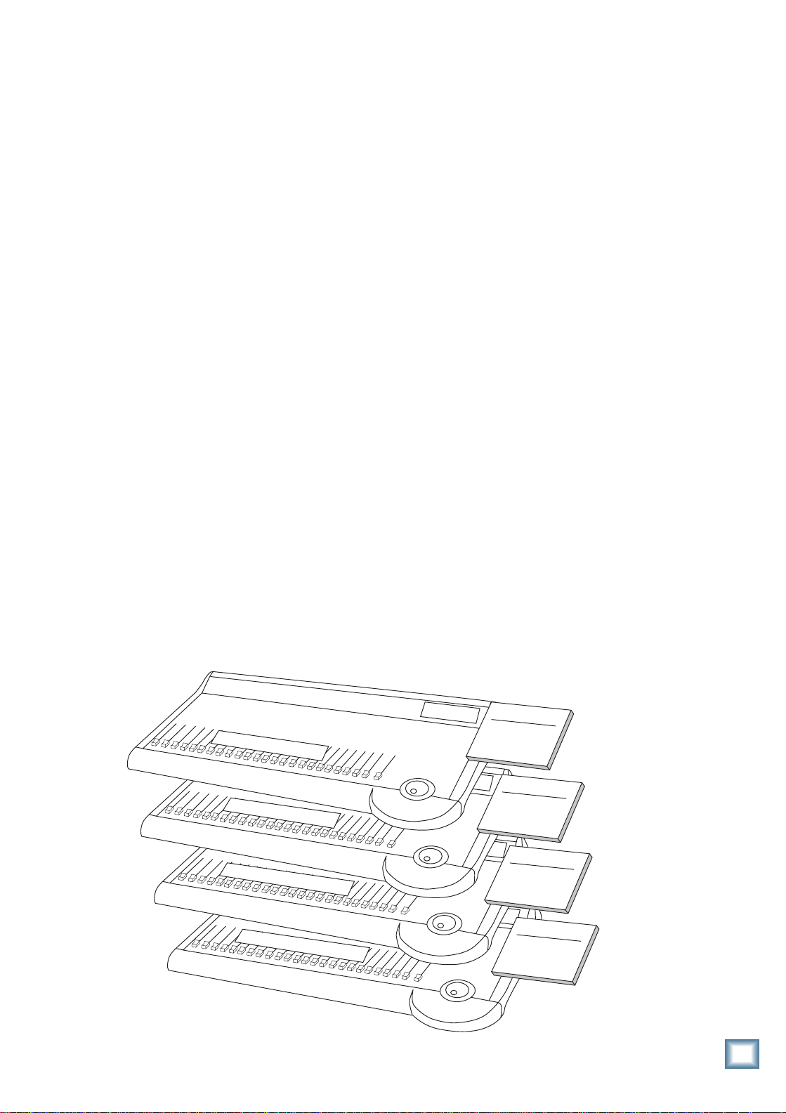
The Digital 8•Bus has four layers of faders,
or fader banks, which can be individually
accessed using the select buttons in the Master
Fader/Bank Select Section. All four banks
operate simultaneously, but only one bank is
accessible at a time.
Fader Bank 1 = Channels 1–24
(1–24 MIC/LINE button)
Fader Bank 2 = Channels 25–48
(25–48 T APE button)
Fader Bank 3 = Internal Effects Returns
FX 1–16, ALT RETurns 1–8
( 49–72 EFFECTS button)
Fader Bank 4 = Virtual Groups 1–8, MIDI
Controllers 1–8, Bus 1–8 Masters
(MASTERS button)
This architecture provides a total of 56
inputs, with Fader Banks 1 and 2 providing 48
inputs, and the 8 ALT Returns in Fader Bank 3
providing another 8 inputs.
One of the primary applications that the
Digital 8•Bus was designed for is multitrack
recording (up to 24 tracks). This involves
tracking and monitoring, bouncing, overdubbing, and mixdown. You can think of Fader
Bank 1 and Fader Bank 2 as two separate
mixing consoles, where Fader Bank 1 is used
for tracking and Fader Bank 2 is used for
monitoring and mixdown.
Three Things to Keep in Mind
As you become familiar with the Digital
8•Bus, you’ll find it helpful to keep these three
questions in mind at all times:
1. What Fader Bank is selected?
2. What channel is selected?
3. What is the V-Pot assignment?
In 90% of the cases, if something isn’ t working as you expect, it is because one of these
three settings isn’ t where you intend it to be.
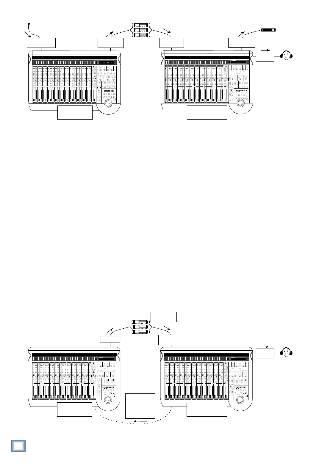
Tracking
The first 24 channels (Fader Bank 1) are
used for tracking; that is, to record instruments
and voices onto individual tracks of the multitrack recorders (refer to Figure 4 on the next
page). Microphones and instruments are directly
connected to the input jacks on channels 1–24,
and their signals are assigned to T ape Outputs
1–24 (and not to the L-R bus). The T ape Outputs
on the Digital 8•Bus are connected to the
inputs of the multitrack recorders where the
instruments and voices are recorded on tape
(or hard disk in the case of a Hard Disk
Recorder or DAW).
C
F
X
R
Figure 3. The Split Console
Fader Bank 1
Channels 1-24
h
a
n
n
e
l
s
1
-
2
4
C
h
a
n
n
e
l
s
2
5
-
4
8
e
t
u
r
n
1
-
1
6
;
A
L
T
R
e
t
u
r
n
1
-
8
G
r
o
u
p
s
1
-
8
;
M
I
D
I
1
-
8
;
B
u
s
1
-
8
Mic/Line
Tracking
Fader Bank 2
Channels 25-48
Monitor/Tape In
Mixdown
Fader Bank 3
FX Return 1-16
ALT Return 1-8
Fader Bank 4
Virtual Groups 1-8
M
I
D
I
C
o
n
t
r
o
l
l
Bus 1-8 Masters
e
r
s
1
-
8
The Basics
5
Page 7
Channels 1-24
MIC/LINE IN
T o Tape From Tape
T ape Outs
or Bus Outs
Digital
Multitrack
Recorders
Tr acks 1-24
T APE IN
L/R MASTER
OUT
DAT Recorder
2-Tr ack
Master
CUE MIX
OUT
Channels 1-24
TRACKING HALF
D i g i t a l 8 • B u s
Fader B ank 1
Figure 4. The Split Console — Tracking
Monitoring
But wait! Of course you want to be able to
monitor the signal as you’re recording it. And
your preference is to monitor the signal actually
recorded onto the tape rather than the signal
going from the console to the tape machines,
so you can hear if there is any distortion or
unusual noise going down. Even if you’re using
all 24 channels for tracking, you’ve only used
half the channels available. There are another
24 channels available for T ape Inputs (Fader
Bank 2). This is the split-console concept.
You can connect all 24 tracks from the
multitrack recorders to the Digital 8•Bus, and
monitor them on channels 25–48, which are
assigned to the L-R bus. The tracking half is
not assigned to the L-R bus, so you can use the
monitoring half to hear the tape outputs on the
L-R bus.
Channels 25-48
MONITORING H ALF
Fader B ank 2
What’s more, all 48 channels have full DSP
capability, so you can apply EQ and effects to
the post-tape signal. And thanks to snapshot
automation, you can even create a rough mix
and store it for future use.
Overdubbing/Bouncing Tracks
The setup is the same throughout the
mixing process. No need to crawl around
behind your gear and move cables around. The
Digital 8•Bus has its own built-in patch bay to
reassign the inputs to various output
destinations.
A corollary of Murphy’s Law states that no
matter how many tracks you have available to
record, you will always need at least one more.
If you need to bounce some tracks down to
make room for the background vocal parts,
simply assign the tracks you want to bounce
Bounce down to
one or two tracks
Bus Outs
Channels 1-24
TRACKING HALF
Fader B ank 1
Figure 5. The Split Console — Bouncing Down
6
The Basics
Digital
Multitrack
Recorders
T ape T r acks In
to
Bus Outs
(This routing
is internal)
ST ART
Tr acks being
bounced
Channels 25-48
MONITORING H ALF
Fader B ank 2
CUE MIX
OUT
Page 8
down to one of the Bus 1–8 Masters (Fader
Bank 4), and assign the Bus Master to any one
(for a mono mix) or two (for a stereo mix) of
the 24 T ape Outputs.
As you bounce the tracks down, you’ll
monitor the previously recorded tracks through
the monitoring half of the console.
Of course, overdubbing is simply recording
while monitoring both the live source and prerecorded tracks.
Mixdown
Mixing down is an art unto itself, but the
Digital 8•Bus gives you the tools to make the
job easier so you can concentrate more on the
art and less on the mechanics. Since the
Digital 8•Bus is fully automated, you can go
through a step-by-step process of adjusting
levels, pans, EQ, and effects. The console
remembers every move you make and plays
them back each time you make a pass, while
you add your creative touch to each and every
track. When you’re done, hit PLAY, sit back
and watch the console perform the complex
tasks you’ve programmed it to do, resulting in
a perfect mix to two-track (or multitrack for
surround-sound applications).
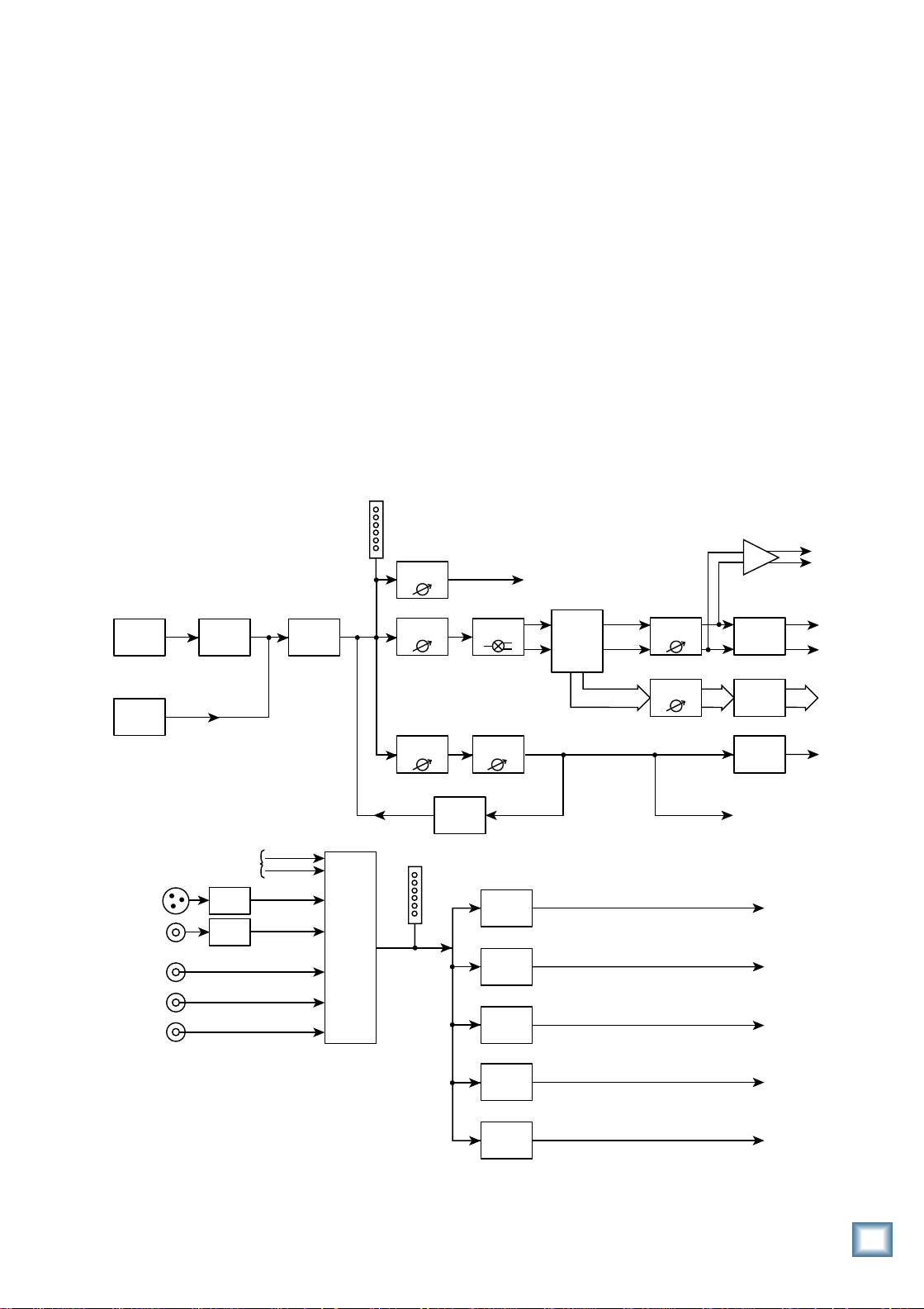
Signal-Flow Diagram
There is a detailed block diagram in the
Digital 8•Bus Owner’ s Manual that shows all
the signal flow and computer-controlled logic
within the console. But since this is a Quick
Start Guide, we thought it might be helpful to
have a simpler signal-flow diagram here that
shows the basic signal flow at a glance so you
don’t have to plod through the detailed drawing.
Q u i c k S t a r t G u i d e
Tracking/Routing
Analog
Inputs
CH 1-48
Optional
Digital Tape
Input
Monitoring
AES/EBU
S/PDIF
2 TRK A
2 TRK B
2 TRK C
Analog to
Digital
Converter
L/R Out
DAC
DAC
From
DSP
Control
Room
Select
Channel
Meter
Returns
Level to
Tape
Channel
Fader
Aux Send
Level
FX
Internal
Main L/R
Meter
FX
Channel
Pan
Master Aux
Send Level
Near Field
Speaker
Level
Main
Speaker
Level
Studio
Level
To Tape Outputs
Bus
Assign
Bus 1-8
AES/EBU Out
S/PDIF Out
L
Master L/R
Fader
R
Bus Master
Digital to
Analog
Converter
Digital to
Analog
Converter
Digital to
Analog
Converter
Lake Sammamish
6 miles
CR
Nearfield
Out
CR
Main
Out
Studio
Out
Main
Out
Bus 1-8
Outputs
Aux
Sends
Figure 6. Simplified Signal-Flow Diagram
Cue Mix 1
Level
Cue Mix 2
Level
Phones 1
Out
Phones 2
Out
The Basics
7
Page 9
3. Tutorial Hookup —
Let’s Get It Working
This is a step-by-step guide to connect a few
things to the Digital 8•Bus and get it working.
Y ou can pop the Quick Start Video into your
VCR and follow along. You will need the
following items to proceed:
1 Electronic Keyboard
1 Stereo Power Amplifier
1 pair of Monitor Speakers (you can
substitute a pair of powered monitors for the
D i g i t a l 8 • B u s
power amplifier/monitor speakers combo)
1 8-track recorder (or multitrack recorder of
your choice)
1 AIO•8 or DIO•8 (T ape I/O card)
Miscellaneous cables
1 cup of coffee (or alternate beverage of your
choice)
and provide additional support at the rear of
the unit.
The connecting cables can reach up to 15
feet, so the Remote CPU must be within 15
feet of the console. If you’re going to use the
optional keyboard/monitor/mouse interface
devices, you’ll want to locate the Remote
CPU close enough for your equipment to
reach your work surface.
3. Connect the DC power cable between the
Remote CPU and the console. Rotate the
outer sleeve of the connector clockwise until
the sleeve is snug and finger-tight.
4. Connect the data cable between the Remote
CPU and the console. Rotate the thumbscrews on each connector clockwise until
they are finger tight.
5. Make sure the POWER switch on the
Remote CPU is off.
6. Connect the detachable linecord to the
Remote CPU.
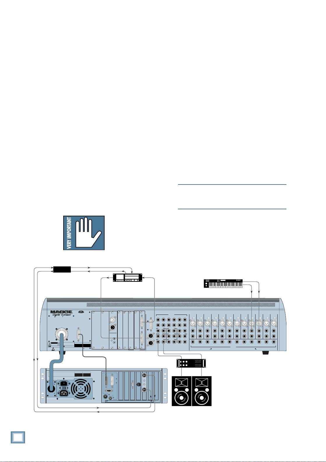
Hookup Stuff
First, connect the Remote CPU to the console.
1. Place the console on your work surface.
2. Place the Remote CPU in some convenient
location nearby. It’ s rack-mountable, so you
can put it in a rack if you so desire.
Caution: The Remote CPU
weighs 42 pounds, so we
recommend that if you
mount it in a rack, you place
it at the bottom of the rack
MIDI Interface
Multitrack Recor der
TAPE 1-8 TAPE 9-16 TAPE 17-24
1
IN
OUT
2
S/PDIF
WARNING:
SHUT OFF REMOTE POWER SUPPLY BEFORE CONNECTING
OR DISCONNECTING POWER SUPPLY CABLE FROM CONSOLE
POWER
SUPPLY
WARNING:
TO REDUCE THE RISK OF FIRE OR ELECTRIC SHOCK, DO NOT
CAUTION
EXPOSE THIS EQUIPMENT TO RAIN OR MOISTURE. DO NOT REMOVE COVER.
NO USER SERVICEABLE PARTS INSIDE. REFER SERVICING TO QUALIFIED PERSONNEL.
RISK OF ELECTRIC SHOCK
DO NOT OPEN
AVIS:
RISQUE DE CHOC ÉLECTRIQUE — NE PAS OUVRIR
UTILISE UN FUSIBLE DE RECHANGE DE MÊME TYPE.
REPLACE WITH THE SAME TYPE FUSE AND RATING.
DEBRANCHER AVANT DE REMPLACER LE FUSIBLE
DISCONNECT SUPPLY CORD BEFORE CHANGING FUSE
WARNING: SHUT OFF POWER TO UNIT BEFORE INSTALLING OR REMOVING CARDS!
56
INPUT72 CHANNEL
CONSOLE
DATA
SERIAL NUMBER
DIGITAL MIXER
A B C D
MANUFACTURING DATE
DIGITAL EFFECTS CARDS DIGITAL I/O SYNC ALT I/O TAPE IN/OUTS
DIGITAL I/O
DIGITAL I/O
IN
OUT
AES/EBU
ANALOG I/O
BUS OUT 1-8
&
SURROUND OUT
L
ANALOG IN ANALOG OUT
R
MASTER OUT
LINE INPUTS
(BAL/UNBAL)
16
172418
23
MASTER OUT
LR
MAIN
LR
NEAR FIELD
LR
THIS DEVICE COMPLIES WITH PART 15 OF THE FCC RULES. OPERATION IS SUBJECT TO THE FOLLOWING TWO CONDITIONS:
1) THIS DEVICE MAY NOT CAUSE HARMFUL INTERFERENCE AND
2) THIS DEVICE MUST ACCEPT ANY INTERFERENCE RECEIVED THAT MAY CAUSE UNDESIRED OPERATION
PHONES 1
2 TRACK IN A
LR
CR
2 TRACK IN B
LR
CR
2 TRACK IN C
PUNCH I/O
LR
MACKIE DESIGNS
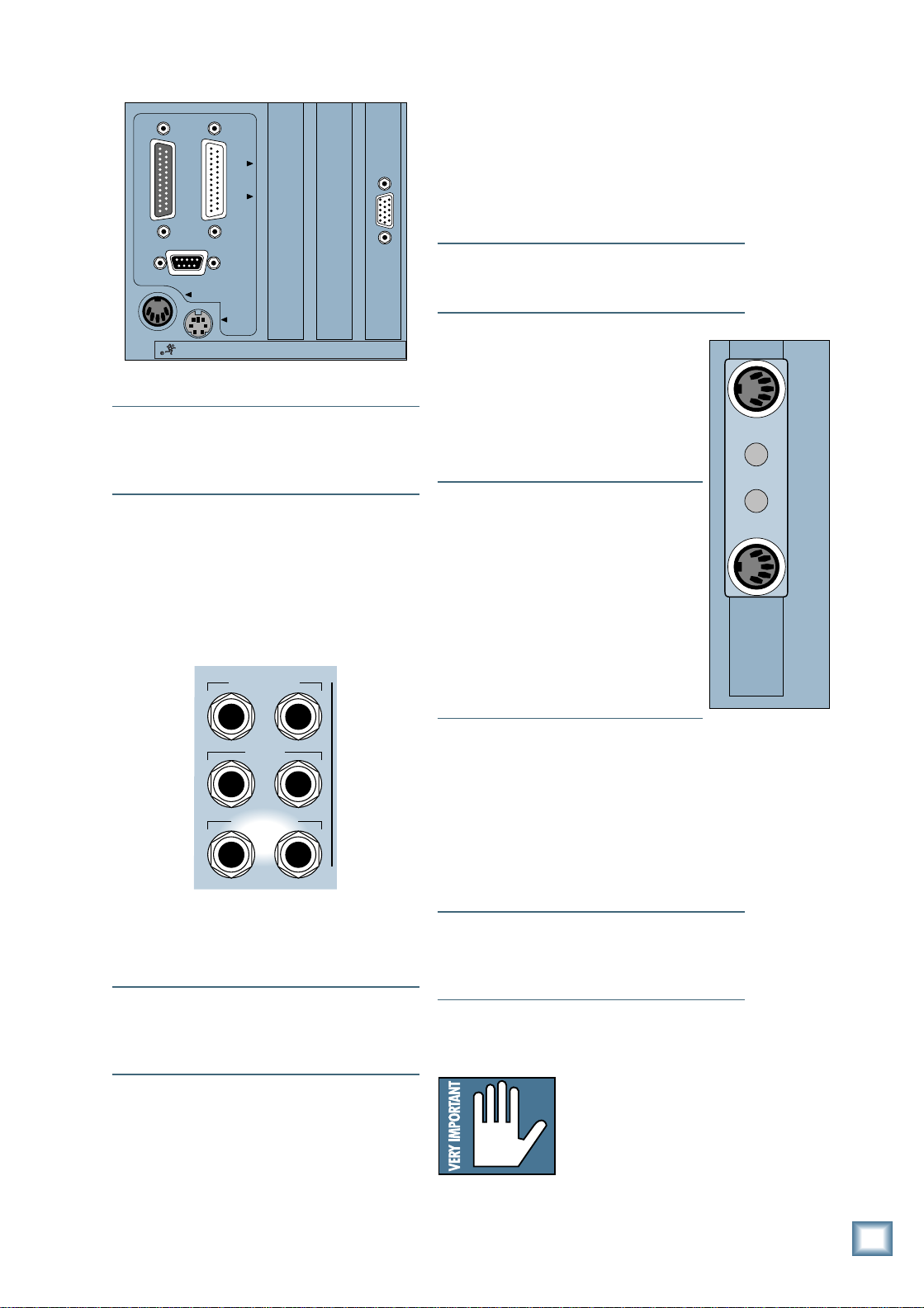
Next, connect the keyboard, mouse, and video
monitor.
Note: These connections are optional, but we
recommend using them to get the most from
your new Digital 8•Bus console.
1. Plug a PC-compatible keyboard into the KEYBOARD port on the back of the Remote CPU.
2. Plug a PS/2-compatible mouse into the
MOUSE port on the back of the Remote CPU.
3. Plug an SVGA video monitor into the VIDEO
port on the back of the Remote CPU.
11
12
13
+48V
+48V
PH
PH
MIC MIC10MIC9MIC8MIC7MIC6MIC5MIC4MIC3MIC2MIC1MIC
19
2014211522
STUDIO OUT
LR
LINE IN
LINE IN
PHONES 2
INSERT
INSERT
TALKBACK
AUX11AUX
12
+48V
+48V
+48V
PH
PH
PH
LINE IN
LINE IN
LINE IN
INSERT
INSERT
INSERT
AUX8AUX9AUX
10
CONCEIVED, DESIGNED, AND MANUFACTURED BY MACKIE DESIGNS INC • WOODINVILLE • WA • USA • MADE IN USA • FABRIQUE AU USA • COPYRIGHT ©1997 •
THE FOLLOWING ARE TRADEMARKS OR REGISTERED TRADEMARKS OF MACKIE DESIGN INC.: "MACKIE", "DIGITAL SYSTEMS", D8B AND THE "RUNNING MAN" FIGURE •
+48V
+48V
+48V
PH
PH
PH
LINE IN
LINE IN
LINE IN
INSERT
INSERT
INSERT
7
AUX OUT
(BAL/UNBAL)
+48V
+48V
PH
LINE IN
INSERT
+48V
+48V
PH
PH
PH
LINE IN
LINE IN
LINE IN
INSERT
INSERT
INSERT
AUX1AUX2AUX3AUX4AUX5AUX6AUX
PATENTS PENDING
DC Power
Cable
MANUFACTURING DATE
MACKIE DESIGNS
THIS DEVICE COMPLIES WITH PART 15 OF THE FCC RULES. OPERATION IS SUBJECT TO
THE FOLLOWING TWO CONDITIONS: 1) THIS DEVICE MAY NOT CAUSE HARMFUL
INTERFERENCE AND 2) THIS DEVICE MUST ACCEPT ANY INTERFERENCE RECEIVED THAT
MAY CAUSE UNDESIRED OPERATION
120V
60Hz, 2.8A
120/230V
1.0/0.5A
SERIAL NUMBER
Figure 7. Quick Start Hookup
8
Tutorial Hookup — Let’s Get It Working
Data Cable
VIDEO
PARALLEL
CONSOLE DATA
SERIAL
KEYBOARD
MOUSE
CONCEIVED, DESIGNED, AND MANUFACTURED BY MACKIE DESIGNS INC • WOODINVILLE • WA • USA • MADE IN USA • FABRIQUE AU USA • COPYRIGHT ©1997 •
THE FOLLOWING ARE TRADEMARKS OR REGISTERED TRADEMARKS OF MACKIE DESIGN INC.: "MACKIE", "DIGITAL SYSTEMS", D8B AND THE "RUNNING MAN" FIGURE •
MIDI In
MIDI Out
Page 10
CONSOLE DATA
PARALLEL
SERIAL
KEYBOARD
CONCEIVED, DESIGNED, AND MANUFACTURED BY MACKIE DESIGNS INC • WOODINVILLE • WA • USA •
THE FOLLOWING ARE TRADEMARKS OR REGISTERED TRADEMARKS OF MACKIE DESIGN INC.: "MACKIE", "D
VIDEO
MOUSE
Note: The video monitor must be a multi-sync
monitor or , if not, capable of at least a 72Hz
scan rate. We recommend using a 17-inch or
larger monitor for best results.
Now connect the audio inputs and outputs to
the console.
1. Using standard “guitar cord”-type cables
with 1/4" phone plugs, connect the Left and
Right CR NEAR FIELD outputs on the rear
panel of the Digital 8•Bus to the left and
right inputs of the power amplifier .
MASTER OUT
LR
If you are using the digital T ape I/O card,
refer to the Digital 8•Bus Owner’s Manual
(Appendix F) for connection information.
The connection on the other end of the cable
depends on your recording deck. It could be
any number of flavors, including Elco, 1/4"
phone plug, RCA phono plug, XLR, 25-pin
D-Sub, 3/4" garden hose, etc.
Note: If you’re using a patch bay , place it
between the Digital 8•Bus and your tape
recorder .
Connections for MIDI
1. On the back of the Remote CPU, plug
the supplied dual output MIDI jack
adapter into the 9-pin D-Sub MIDI
connector . The output jack has standard
5-pin MIDI IN and OUT sockets on it.
Connect these to the MIDI IN and
OUT connectors on your recorder .
Note: Most recorders require a MIDI
interface box to go between an external
MIDI control device such as the Digital
8•Bus, and its own MIDI I/O. Check
your recorder’s manual for more
information.
Note: If you’re using more than one 8track recorder , you may need to match
your device ID with that of the Digital
8•Bus’ software. Please consult the
Digital 8•Bus Owner’ s Manual and your
recorder’s manual for proper settings.
Q u i c k S t a r t G u i d e
MIDI
OUT
MIDI
IN
CR
MAIN
LR
CR
NEAR FIELD
LR
2. Using heavy-gauge speaker wire appropriate
for the power of the amplifier , connect the
left and right outputs of the power amplifier
to the speaker inputs.
Note: If you’re using powered monitors,
connect the Left and Right CR NEARFIELD
outputs directly to the line inputs on the
powered monitors.
3. To connect a recording deck to the Digital
8•Bus, it is necessary to have at least one of
the optional T ape I/O cards installed. For this
example, we’ll use an analog T ape I/O card.
This card has two 25-pin D-Sub connectors
for connecting the analog T ape I/O signals to
your tape deck.
Optional Refreshments
1. Take a sip of coffee.
Power-Up
• Make sure the POWER switch on the
Remote CPU is off. Now plug the linecord
into an AC outlet properly configured for
your model.
Note: The Remote CPU should be treated as
you would any computer . We recommend that
you use a UPS (Uninterruptible Power Supply)
and a surge protector on the AC line.
• Leave the POWER switch off while
connecting the peripheral equipment to the
console.
Caution: Never connect or
disconnect anything except
microphone or line-level
inputs while the console is
powered up.
Tutorial Hookup — Let’s Get It Working
9
Page 11
T urn on the power switch on the front panel
of the Remote CPU, then turn on the power to
all your peripheral equipment. The Digital
8•Bus takes a few moments to load the Mackie
Real Time OS (Operating System) and initialize
the DSPs. When the Vacuum Fluorescent Display
in the Fat Channel Section indicates EQ settings
for channel 1, the console is ready to use.
Now we’ll look at some of the basics like
setting up system options, creating a session,
and creating a default snapshot.
Downloading Plug-Ins
Before beginning a session, you can
download the effects algorithms of your choice
to the internal FX cards.
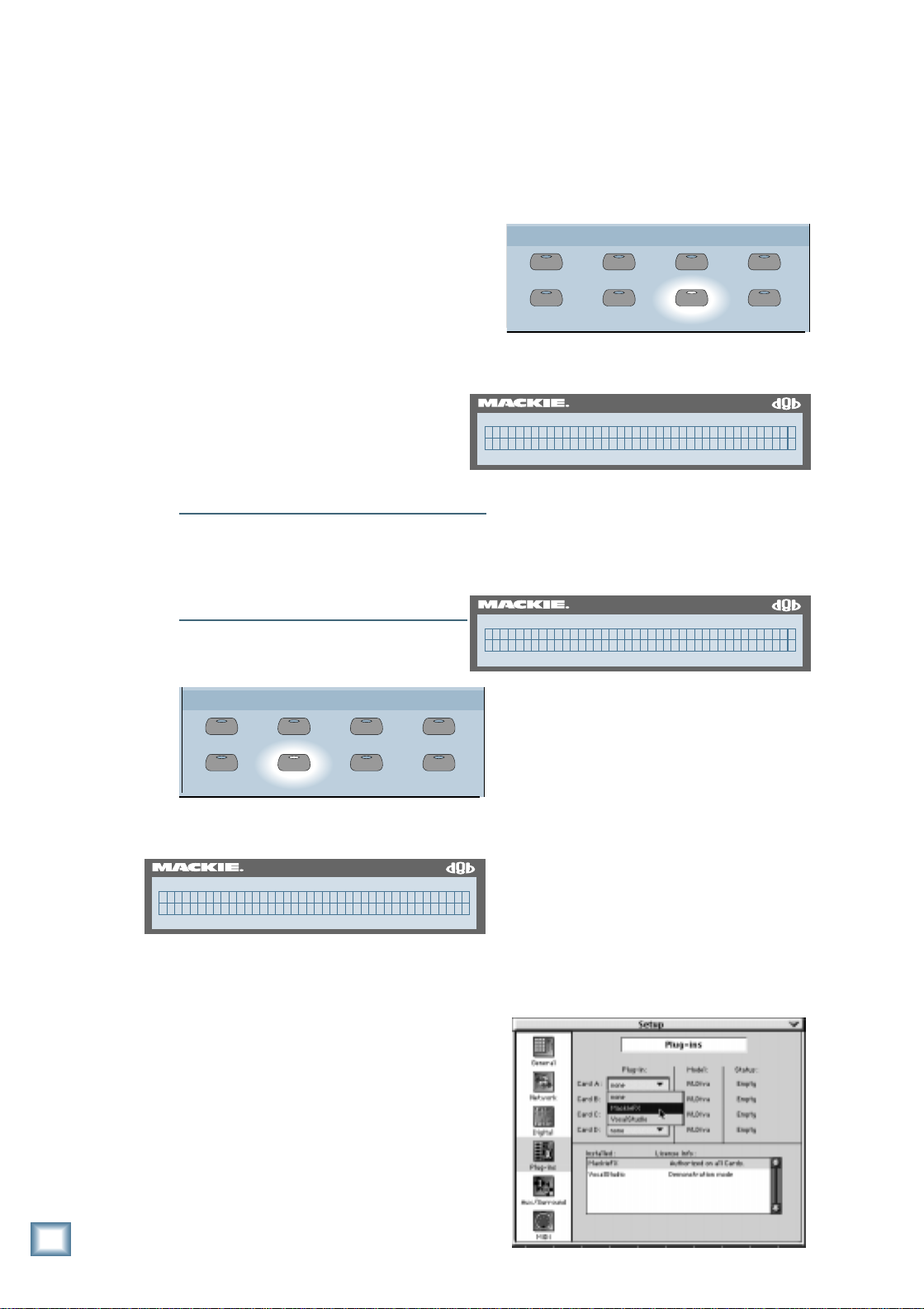
Loading Effects with Console Controls:
• Press the PLUG INS button in the Setup
Section.
SETUP
SAVE
SAVE AS... NEW
LOAD
D i g i t a l 8 • B u s
Start-up
System Options
The system options are found in the
General Setup menu. You should confirm
that all the system settings are correct for
your configuration and application. Go here
to set the language, surround mode, MIDI
settings, Auto Save settings, and Aux
Pre/Post Fader setting.
Note: If you’re using a digital T ape I/O card,
you’ll need to do some additional software
setups. See the section called “Configuring
Digital I/O” in Chapter 3 of the Digital
8•Bus Owner’s Manual.
• Press the GENERAL button in the Setup
Section.
SAVE
GROUP
SAVE AS... NEW
GENERAL PLUG INS DIGITAL I/O
SETUP
LOAD
GROUP
GENERAL PLUG INS DIGITAL I/O
A menu of options appears in the Fat
Channel Display.
D8B
56 INPUT / 72 CHANNEL DIGITAL MIXER
Pick a Card to setup: (PLUGIN SETUP)
Card A Card B Card C Card D
• Press the SELECT button below the card
you want to configure. The basic console
ships with one FX card installed (CARD A).
Y ou can purchase and install up to three more
cards to provide more simultaneous effects.
D8B
56 INPUT / 72 CHANNEL DIGITAL MIXER
MackieFX (PLUGIN-CARD1)
<< >> Cancel Transmit
• Use the SELECT buttons below the arrows
in the Fat Channel Display to scan through
available Plug-Ins. When the Plug-In you
want appears, press the SELECT button
below Transmit to download the algorithm
to the selected FX Card.
10
A menu of options appears in the Fat
Channel Display.
D8B
56 INPUT / 72 CHANNEL DIGITAL MIXER
(GENERAL SETUP Pg1 ->)
Language Surround MIDI AutoSave
• Press the SELECT button below the option
you want to change and a new menu
appears related to that specific option.
• In general, use the SELECT buttons to scan
through available options, and use the V-Pots
to adjust parameters (where applicable). Use
the PREVIOUS and NEXT buttons to page
over to more options (if available).
Refer to Chapter 3 (“Start-Up”) in the
Digital 8•Bus Owner’s Manual for more details
on each option.
Tutorial Hookup — Let’s Get It Working
Loading Effects with Mouse and Monitor:
• Click on the “Setup” button in the lower
menu bar . The Setup dialog box window
appears on the screen.
• Click on “Plug-Ins” on the left side of the
setup window .
• Click on the box next to CARD A and select
Mackie FX from the drop-down menu. As
soon as it’ s selected, the algorithm is
downloaded to the FX Card.
Page 12
Getting Sound Out
Now that you have set all the options the
way you want them, we can make a sample
recording and see how the Digital 8•Bus
actually works.
• First, connect a keyboard to channels 3 and
4 line inputs. Channels 3 and 4 MIC buttons
should be in the UP position. Turn the faders
all the way down, including the MASTER
L-R fader .
• Select Fader Bank 1 (MIC/LINE 1–24).
MASTERS
1-24
MIC/LINE
(TRACK) (MONITOR)
SHIFT
25-48
TAPE IN
• Make sure the MASTER L-R button and the
NEAR FIELD button are lit in the Control
Room Section.
CONTROL ROOM
2 TRACK A
2 TRACK B
2 TRACK C
NEAR FIELD
MONO
SPEAKERS
DIGITAL IN 1
DIGITAL IN 2
MASTER
L-R
MAIN
TRIM
0
-
20dB
REC/RDY
ASSIGN
WRITE
12
MIC
Q u i c k S t a r t G u i d e
N
E
I
L
C
I
M
60
+40dB
49-72
EFFECTS
BANK SELECT
• Set the source — in this case, the keyboard
— for unity output level, and watch the
channel meters as you adjust the TRIM knob.
Note: The channel meters are pre-fader , so you
don’ t need to adjust the faders for this operation.
• Set the TRIM for a meter indication around
–15 (the fat bar on the meter). Under no
circumstances should the levels go to the top
OL on the meter or you will experience digital
clipping, which is a most unpleasant sound.
12
36
OL
Sounds Ugly
2
4
7
10
Just Right
15
20
25
30
35
40
Too Low
50
• Bring up the faders on channels 3 and 4
while the keyboard is providing an input
signal. Set the faders at the unity gain mark.
• Slowly bring up the MASTER L-R fader . You
may or may not hear sound, depending on
the settings in the Control Room Section.
Set it at or near the unity gain mark.
SPEAKER LEVEL
DIM
TALKBA CK
• While playing the keyboard, slowly rotate
the SPEAKER LEVEL V-Pot in the Control
Room Section and set it at a comfortable
listening level.
Preparing to Record
Now that input levels are set, we want to
monitor the returns from the recording deck
rather than the channel inputs. T o avoid double
monitoring, turn off the L-R bus assignment on
channels 3 and 4.
• With Fader Bank 1 (MIC/LINE 1–24)
selected, press the MASTER L-R button in
the Bus Assignment Section.
ASSIGNMENT
ASSIGN ASSIGN
BUS 1
ASSIGN ASSIGN
BUS 3 BUS 4
ASSIGN ASSIGN
BUS 5
ASSIGN ASSIGN
BUS 7
ASSIGN ASSIGN
L-R
• T urn off the ASSIGN buttons on channels 3
and 4.
BUS 2
BUS 6
BUS 8
ROUTE TO
TAPE
MIDI 4
FX 12
dB
10
5
U
5
10
20
30
40
50
60
12
36
SELECT
SOLO
MUTE
12
36
Tutorial Hookup — Let’s Get It Working
11
Page 13
SHIFT
MASTERS
1-24
25-48
49-72
(TRACK) (MONITOR)
BANK SELECT
EFFECTS
MIC/LINE
TAPE IN
SHIFT
MASTERS
1-24
25-48
49-72
(TRACK) (MONITOR)
BANK SELECT
EFFECTS
MIC/LINE
TAPE IN
TRIM
L
Assigning Channels 3 and 4 to T racks 3 and 4.
• Select Fader Bank 2 (T APE IN 25–48).
• Make sure Fader Bank 1 is selected (1–24
MIC/LINE).
N
E
I
C
I
M
60
0
+40dB
-
20dB
12
MIC
D i g i t a l 8 • B u s
REC/RDY
ASSIGN
WRITE
• Press the ROUTE TO T APE button in the
MASTERS
1-24
MIC/LINE
(TRACK) (MONITOR)
Bus Assignment Section.
ASSIGNMENT
ASSIGN ASSIGN
12
36
SELECT
SOLO
MUTE
BUS 1
ASSIGN ASSIGN
BUS 3 BUS 4
ASSIGN ASSIGN
BUS 5
ASSIGN ASSIGN
BUS 7
ASSIGN ASSIGN
L-R
49-72
EFFECTS
BANK SELECT
SHIFT
25-48
TAPE IN
BUS 2
BUS 6
BUS 8
ROUTE TO
TAPE
• Press the ASSIGN buttons on channels 27
and 28 to assign them to the Left/Right bus.
Now arm tracks 3 and 4:
• Select Fader Bank 1 (MIC/LINE 1–24).
10
5
U
5
10
20
30
40
50
60
MIDI 4
FX 12
dB
12
36
• Press the SELECT button on channel 3.
• Press the ASSIGN button on channel 3.
Channel 3 is now assigned to Tape Out 3, which
goes to T rack 3 on your multitrack recorder.
• Press the SELECT button on channel 4.
• Press the ASSIGN button on channel 4.
Channel 4 is now assigned to Tape Out 4, which
goes to T rack 4 on your multitrack recorder.
Next, assign channels 27 and 28 (which are
T ape Out 3 and 4 from the multitrack) to the
Left/Right Bus:
• Press the MASTER L-R button in the Bus
Assignment Section.
ASSIGNMENT
ASSIGN ASSIGN
BUS 1
ASSIGN ASSIGN
BUS 3 BUS 4
ASSIGN ASSIGN
BUS 5
ASSIGN ASSIGN
BUS 7
ASSIGN ASSIGN
L-R
BUS 2
BUS 6
BUS 8
ROUTE TO
TAPE
• Press the REC/RDY buttons on channels 3
and 4 to arm the tracks for recording, or
press the corresponding buttons on the tape
recorder .
• Start playing the keyboard. The meter
indications on the tape recorder should be
equivalent to the meter indications on the
console.
Important: The channel
faders do NOT set output
levels to the recorder . If the
meter indications on the
recorder are too high or too
low , you can adjust the
levels by pressing the LEVEL TO T APE
button in the V-Pot Select Section. The
channel V-Pots become level controls for the
tape outputs. Adjust the V-Pots so the meter
indication on the tape recorder is at its
recommended level.
Next, get signal from the tape back to the console
and out the Control Room speakers (or
headphones):
• Put your multitrack recorder into Record/
Pause mode. This will allow the signal to
pass through the recorder and back to the
console.
12
Tutorial Hookup — Let’s Get It Working
Page 14

• Select Fader Bank 2 (T APE 25–48).
SHIFT
MASTERS
1-24
25-48
49-72
(TRACK) (MONITOR)
BANK SELECT
EFFECTS
MIC/LINE
TAPE IN
MASTERS
1-24
MIC/LINE
(TRACK) (MONITOR)
SHIFT
25-48
TAPE IN
49-72
EFFECTS
BANK SELECT
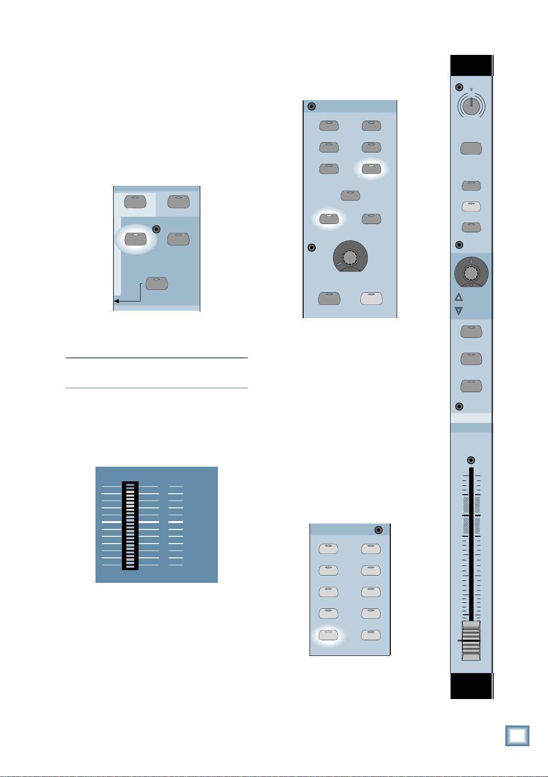
• Rotate the first V-Pot in the Fat Channel
Section to select the effect you want to use
with Aux 1. Press the NEXT button to scroll
through the various parameters of the effect
and adjust accordingly.
D8B
56 INPUT / 72 CHANNEL DIGITAL MIXER
Aux 1 (STANDARD EFFECTS)>
Reverb Version 1.0
SUPER CD ENCODING
SELECT
SELECT SELECT
Q u i c k S t a r t G u i d e
SELECT HELP
• T urn the faders down on channels 27 and
28. The TRIM control at the top of the
channel strip has no effect when Fader
Bank 2 is selected.
• Start playing the keyboard and you should
see the meter on channel 27 indicating the
signal.
• Slowly increase the faders on channels 27
and 28 to their unity position. You should
hear the signal in the speakers. If it’s too
loud, turn the SPEAKER LEVEL V-Pot
down in the Control Room Section.
Y ou can add effects to the monitor signal,
without affecting the signal being recorded
onto tape.
• Select AUX 1 in the V-Pot Select Section.
1-24 1-48
LEVEL TO TAPE
AUX 1
DIGITAL TRIM
AUX 2
LOWPREVIOUS
ON
EQ
LOW MID HI MID
SETUP
COMPRESSORGATE
MEMORY A
PLUG-INS
• Adjust the V-Pots on channels 27 and 28 to
set their aux send levels.
• Adjust the Master V-Pot to set the overall
aux send level to the internal FX card.
MASTER
PAN
SOLO
• Select Fader Bank 3 (EFFECTS 49–72). In
this bank, faders 1 and 2 adjust the effects
return level of Aux 1. T o hear the effects,
bring up faders 1 and 2. Make sure they are
assigned to the L-R bus.
HI NEXT
MEMORY B
LOAD PATCH
SAVE PATCH
AUX 3
AUX 5
AUX 7
AUX 4
AUX 6
AUX 8
• Press the PLUG-INS button in the Fat
Channel Section.
SUPER CD ENCODING
EQ
SELECT
LOWPREVIOUS
ON
SELECT SELECT
LOW MID HI MID
SETUP
COMPRESSORGATE
MEMORY A
PLUG-INS
LOAD PATCH
SELECT HELP
HI NEXT
MEMORY B
SAVE PATCH
Tutorial Hookup — Let’s Get It Working
13
Page 15

Saving Your Session
When you first turn on the Digital 8•Bus, a
session named Startup is loaded by default.
Y ou should create a new session any time you
start a new project. After you’ve started a project,
it’s a good idea to save it under a new name
whenever you want to backup what you’ve already
done. That way, if things go haywire, you can
always go back to where you were and try again.
Saving your session with console controls:
• Press the SAVE AS... button in the Setup
Section.
D i g i t a l 8 • B u s
SETUP
SAVE
GROUP
SAVE AS... NEW
GENERAL PLUG INS DIGITAL I/O
LOAD
• A suggested name for the session appears in
the Fat Channel Display . You can either accept
the suggested name, or you can enter a new
name.
D8B
56 INPUT / 72 CHANNEL DIGITAL MIXER
mix#1 (SAVE SESSION AS)
<< >> Cancel OK
• To enter a new name, use the V-Pot to
change the characters, and use the SELECT
buttons to move the cursor.
• When you’ve finished, press the SELECT
button under OK to save the new session.
Saving your session with mouse and monitor:
• Click on “File” in the upper menu bar . Select
“Save Session As...” from the drop-down menu.
• The Save File As... dialog box appears with
a suggested name for the session. You can
either accept the suggested name, or type in
a new name with the keyboard.
• When you’ve finished, click on the “Save”
button to complete the operation.
Creating a Default Snapshot
A snapshot is just what it implies; it’s a
picture of all the settings of the console (except
for the analog T rim controls, which aren’t
automated). The Digital 8•Bus has a default
snapshot saved in memory called Normalled.
Recalling this snapshot places the console into
what we consider to be a normal state, with
faders down, pans centered, aux sends off, etc.
This allows you to quickly reset the console
back to a convenient starting point when you
finish a project.
You may prefer different normal settings for
the console (for example, with all the faders at
unity). If so, you can create a default snapshot
for quickly normalling the console to the
settings you prefer .
T o create a default snapshot:
• Set all the controls on the console to your
preferred positions.
• Press the SNAPSHOT button in the
T ransport Section.
• Press the STORE button.
• Enter two digits with the number buttons
that haven’ t been used yet for a snapshot
(for example, enter “05”).
• Press the ENTER button. The default
snapshot has now been stored in memory.
FROM TO
0500000000
RANGE
SET TIME
SMPTE VIEW
POSITION
MINUTESHOURS
SECONDS FRAMES
BEATS LOOP
BARS
TICKS
14
Tutorial Hookup — Let’s Get It Working
1
6
ENTER
REWIND
SHUTTLE
2
7
LOOP
FAST F WD
STORE
STOP
MODE
5
0
SNAPSHOT
RECORD
3
8
4
9
LOCATOR
PLAY
Page 16

To recall your new default snapshot:
• Make sure the SNAPSHOT button in the
Transport Section is on.
• Enter the two-digit number you used to store
your default snapshot with the number
buttons (for this example, enter “05”).
• Press the ENTER button. The snapshot is
now loaded into the console.
Y ou can store and recall up to 100
snapshots from the console surface (00–99),
and up to 150 from the screen.
Note: Snapshots are stored with the current
session and cannot be copied from one session
to another .
Obviously, there’ s a lot more to using the
Digital 8•Bus, and we’ll get into a little more
depth further on in the Quick Start Guide. The
purpose of this exercise is to show you the
fundamentals of getting signal to the tape
recorder and back.
4. General Guidelines
Three Things to Keep in Mind
(Reprise)
This is a reminder , that as you become
familiar with the Digital 8•Bus, you’ll find it
helpful to keep these three questions in mind
at all times:
1. What Fader Bank is selected?
2. What channel is selected?
3. What is the V-Pot assignment?
In 90% of the cases, if something isn’ t working like you expect, it is because one of these
three settings isn’t where you intend it to be.
Setting Levels
and pan controls centered. Snapshot 00 is
pre-programmed with our default factory
settings—our version of a “normalled”
console. You can reprogram Snapshot 00
so that it resets the console to your
preferred “normal state,” or keep the
factory default settings and save your own
settings to another snapshot (Snapshot
01, for example). See “Creating a Default
Snapshot” in the previous section.
2. Connect a signal to a channel.
• If the channel is used with a microphone,
the MIC switch should be down.
• If the channel is used with a line input,
the MIC switch should be up.
3. Connect the Control Room output to your
control room amplifier/speaker
combination, so you can monitor the signal.
MASTER OUT
LR
CR
MAIN
LR
CR
NEAR FIELD
LR
4. Select Fader Bank 1 by pressing the MIC/
LINE (1–24) button.
MASTERS
1-24
MIC/LINE
(TRACK) (MONITOR)
SHIFT
25-48
TAPE IN
-
20dB
MIDI 4
dB
10
5
TRIM
N
I
L
M
0
12
MIC
REC/RDY
ASSIGN
WRITE
12
36
SELECT
SOLO
MUTE
FX 12
12
36
C
I
E
+40dB
Q u i c k S t a r t G u i d e
60
Input Sensitivity Adjustment
Procedure for Channels 1–24
(–15 dB FS on the meter is equivalent to
+5 dBu analog)
The input sensitivity adjustment procedure
is similar to that of an analog mixing console
because the input section for channels 1–24 is
the same as our analog large-format consoles.
FOLLOW THIS SENSITIVITY ADJUSTMENT
PROCEDURE FOR EACH CHANNEL IN USE
(Channels 1–24):
1. If you’re starting out from scratch, it’s a
good idea to normal the console (also
called “zeroing”) to some starting point,
such as all level controls down, and EQ
49-72
EFFECTS
BANK SELECT
5. Set the channel strip controls as follows:
TRIM controls all the way counterclockwise (–20 dB), and all the faders to
their “U” (unity) markings. Turn the
MASTER L-R fader all the way down.
General Guidelines
U
5
10
20
30
40
50
60
15
Page 17

6. Press the PFL SOLO button in the
STUDIO/SOLO section. In this mode the
faders do not affect the solo level at the
Control Room output.
MIXDOWN SOLO
PFL SOLO
AFL SOLO
D i g i t a l 8 • B u s
TALKBACK TO
STUDIO
7. Press the channel SOLO button. The LED
in the button lights.
8. Make appropriate “noise” into the channel
input. For example, have a performer play/
sing/strike something or someone, etc. at
the level they’re going to record or perform.
Don’ t just play a single sustained note, but
rather, jam away as you would during a
recording or performance. If the channel is
being used for a tape input during
mixdown, roll an already-recorded track
from your recorder .
9. Adjust the TRIM control. The goal is to
get the channel meter reading at or around
–15. The peaks should regularly hit, and
occasionally exceed, the –15 designation
on the meter . This is equivalent to a
+4 dBu analog level, and provides plenty
of headroom for transient peaks before
reaching 0 dB FS.
T o monitor the signal, press SOLO LEVEL
in the Studio/Solo Section and adjust the
LEVEL V-Pot. Make sure the SPEAKER
LEVEL V-Pot in the Control Room Section
is turned up.
10. If desired, press the channel’s SELECT
button and adjust the EQ in the Fat
Channel (see “Using Internal Channel
Processing and Internal Effects” in the
next section). You may need to readjust the
channel’s TRIM control after changing the
EQ setting.
11. Repeat steps 5–10 on the next channel
that is being used.
12. Once you’ve achieved the proper input
sensitivity settings using this method,
clear all soloed channels and monitor the
mix in the Control Room outputs (with all
channels assigned to the L-R bus, and L-R
selected as the Control Room source) or
the Main L-R Output. Slowly bring up the
Master L-R fader to a comfortable listening
level and use the channel faders to adjust
individual levels. Leave the TRIM controls
alone. This will give you the best signal-tonoise ratio in your mix.
16
General Guidelines
STUDIO/SOLO
RUDE SOLO
LIGHT
LEVEL
CLEAR SOLO
SOLO LEVEL
STUDIO LEVEL
TALKBACK LEVEL
Note: If you use the built-in compressor on any
channels, you can get away with turning the
TRIM control up a little higher , since the
compressor will reduce the chance of transient
peaks reaching digital clipping. Of course, the
tradeoff is that you will lose some dynamic
range (see “Using The Compressor” in Chapter
6 of the Digital 8•Bus Owner’s Manual).
Using Internal Channel Processing
and Internal Effects
Every channel on the Digital 8•Bus has its
own individual 4-band parametric EQ,
compressor , and gate. In fact, each channel can
store two separate settings for the EQ,
compressor , and gate. Want more? You can
dynamically automate the settings for the EQ,
compressor , and gate referenced to time code,
using the built-in Mackie Real Time OS
Automation software.
EQ
When you press a channel’s SELECT button,
its channel number appears in the CHANNEL
SELECT display, and its EQ settings appear in
the Fat Channel Display. If they don’t, make
sure the EQ button in the Fat Channel Section
is lit. Also make sure the ON button is lit.
SUPER CD ENCODING
SELECT
LOWPREVIOUS
ON
EQ
• You can toggle through the parameters
(gain, frequency, Q) for each band by
pressing the SELECT button under each
parameter in the Fat Channel Display.
• You can adjust a parameter’ s value by
turning the V-Pot below each parameter.
• The EQ settings are stored in MEMORY A.
Press the MEMORY B button to create a
different EQ curve. Now you can quickly
switch back and forth between the two EQ
settings to compare how they sound, or to
make a deliberate change to the sound of
the instrument or voice in real time.
SELECT
LOW MID
SETUP
COMPRESSORGATE
Page 18

Gate
56 INPUT / 72 CHANNEL DIGITAL MIXER
D8B
Pick a Card to setup: (PLUGIN SETUP)
Card A Card B Card C Card D
56 INPUT / 72 CHANNEL DIGITAL MIXER
D8B
MackieFX (PLUGIN-CARD1)
<< >> Cancel Transmit
Press the GA TE button to view the selected
channel’s gate settings.
SUPER CD ENCODING
SELECT
LOWPREVIOUS
ON
EQ
SELECT
LOW MID
SETUP
COMPRESSORGATE
• Y ou can adjust each parameter’s value by
turning the V-Pot below each parameter.
• Press the NEXT button to view offscreen
parameters that won’ t fit in the display.
• The gate settings are stored in MEMORY A.
Press the MEMORY B button to create
different settings for the gate. Now you can
quickly switch back and forth between the
two gate settings to compare how they
sound, or to make a deliberate change to the
sound of the instrument or voice.
Compressor
Press the COMPRESSOR button to view the
selected channel’s compressor settings.
SUPER CD ENCODING
SELECT
SELECT
to create different settings for the compressor ,
perhaps to make it work as a limiter . Now
you can quickly switch back and forth
between the two compressor settings to
compare how they sound, or to make a
deliberate change to accomodate a variation
in the dynamics of an instrument or voice.
Internal Effects
The Digital 8•Bus is shipped with one
internal effects card (MFX
card is capable of processing two discrete
mono input/stereo output digital effects. Y ou
can install up to three more effects cards, for a
total of eight mono input/stereo output digital
effects that can operate simultaneously.
The first eight Aux Sends are normalled to
the internal effects cards:
Aux 1 and 2 feed Card A
Aux 3 and 4 feed Card B
Aux 5 and 6 feed Card C
Aux 7 and 8 feed Card D
The stereo returns from the internal effects
cards are the 16 FX RETURNS in Fader Bank 3:
Card A = FX 1 and 2
Card B = FX 5 and 6
Card C = FX 9 and 10
Card D = FX 13 and 14
Plug-Ins
™
MFX
The Mackie Standard Effects Package
contains a variety of effects that you can
download to the FX cards, including reverb,
chorus, and delay.
• Press the PLUG-INS button in the Setup
Section and the Plug-Ins setup menu
appears in the Fat Channel Display.
™
) installed. This
FX 3 and 4
FX 7 and 8
FX 11 and 12
FX 15 and 16
Q u i c k S t a r t G u i d e
LOWPREVIOUS
ON
EQ
• Y ou can adjust each parameter’s value by
turning the V-Pot below each parameter.
• Press the NEXT button to view offscreen
parameters that won’ t fit in the display.
• The compressor settings are stored in
MEMORY A. Press the MEMORY B button
LOW MID
SETUP
COMPRESSORGATE
• Press the SELECT button below the card
you want to configure.
• Press the SELECT buttons below the arrows
in the display to scroll through the available
plug-ins.
General Guidelines
17
Page 19

• When the plug-in you want to use appears in
SHIFT
MASTERS
1-24
25-48
(TRACK) (MONITOR)
MIC/LINE
TAPE IN
AUX 7
AUX 8
AUX 5
AUX 6
AUX 1
AUX 3
AUX 2
AUX 4
LEVEL TO TAPE
DIGITAL TRIM
1-24 1-48
the display, press the SELECT button below
TRANSMIT. The selected plug-in will now
be downloaded to the FX Card.
• Repeat for each card you have installed.
Now that you’ve configured the cards with
the effects you want to use, you can adjust the
individual parameters for each effect.
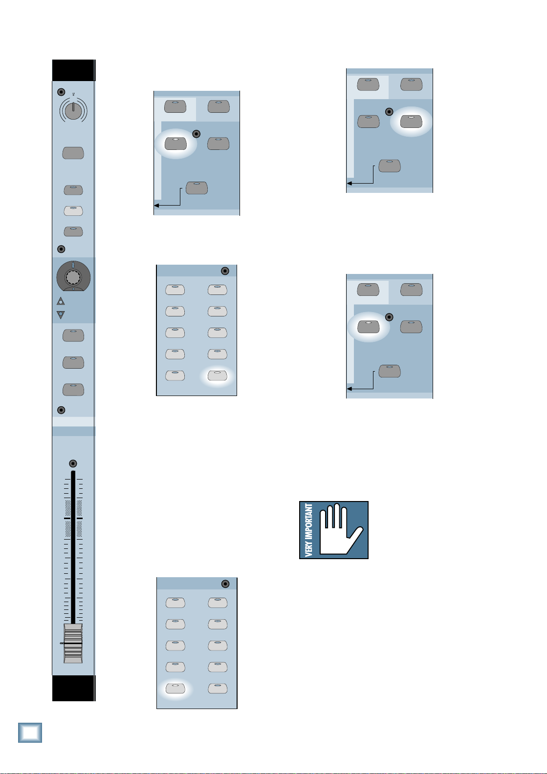
• Press the PLUG-INS button in the Fat
Channel Section.
D i g i t a l 8 • B u s
SELECT
SELECT SELECT
Refer to “Selecting Internal Effects” in
Chapter 6 of the Digital 8•Bus Owner’ s Manual
for more information on the Mackie FX plug-in.
Once you’ve configured the cards with the
effects you want and adjusted the parameters
for each effect, you can assign individual
channels to the aux send that corresponds to
the effect you desire for each channel. As an
example, let’s say that you have Card A
programmed with reverb on Aux 1 and delay
on Aux 2, and you want to add reverb to tape
returns channels 25 through 28, and delay to
channel 29.
• Press the T APE IN button in the Master
Fader/Bank Select Section to select Fader
Bank 2.
SUPER CD ENCODING
LOW
ON
LOW MID HI MID
SETUP
COMPRESSORGATE
MEMORY A
PLUG-INS
• The Fat Channel Display instructs you to
select an Aux Send that has an FX Plug-In
Card installed. If you have only one card
installed, press AUX 1 or AUX 2 in the V-Pot
Select Section.
• Rotate the first V-Pot to scroll through the
available effects for the selected FX card.
Stop when the one you want appears in the
display.
D8B
56 INPUT / 72 CHANNEL DIGITAL MIXER
Aux 1 (STANDARD EFFECTS)>
Reverb Version 1.0
SELECT
SELECT SELECT
SELECT HELP
• Press AUX 1 in the V-Pot Select Section.
• The channel V-Pots are now Aux 1 send
level controls. Adjust the V-Pots on channels
25 through 28 for the amount of send level
you want to send to the Aux 1 bus.
18
General Guidelines
LOWPREVIOUS
ON
EQ
LOW MID HI MID
SETUP
COMPRESSORGATE
MEMORY A
PLUG-INS
HI NEXT
MEMORY B
LOAD PATCH
SAVE PATCH
REC/RDY
ASSIGN
WRITE
REC/RDY
ASSIGN
WRITE
REC/RDY
ASSIGN
WRITE
REC/RDY
ASSIGN
WRITE
• Press the NEXT button to view the
parameters associated with the selected
effect. Rotate their corresponding V -Pots to
adjust their parameters to taste.
1
25
26
2
27
3
4
28
Page 20

• Adjust the Master V-Pot in the Master V -Pot
Section to adjust the overall amount of Aux
1 signal to send to the internal reverb.
MASTER
• Adjust FX 1 and 2 faders and pans for the
amount of reverb you want returned to the
L-R bus.
• Adjust FX 3 and 4 faders and pans for the
amount of delay you want returned to the
L-R bus. Make sure FX 1–4 are assigned to
the L-R bus.
Q u i c k S t a r t G u i d e
PAN
SOLO
• Press AUX 2 in the V-Pot Select Section.
• Adjust the channel 29 V -Pot for the amount of
send level you want to send to the Aux 2 bus.
• Adjust the Master V-Pot in the Master V -Pot
Section to adjust the overall amount of Aux
2 signal to send to the internal delay.
• Press the MASTER L-R button in the Bus
Assignment Section.
ASSIGNMENT
ASSIGN ASSIGN
BUS 1
ASSIGN ASSIGN
BUS 3 BUS 4
ASSIGN ASSIGN
BUS 5
ASSIGN ASSIGN
BUS 7
ASSIGN ASSIGN
L-R
BUS 2
BUS 6
BUS 8
ROUTE TO
TAPE
• Press the ASSIGN buttons on channels 25
through 28 if you want the dry signal returned
to the L-R bus. Leave the ASSIGN buttons
off if you want only the wet signal returned
to the L-R bus via the internal effects returns.
• Press EFFECTS in the Master Fader/Bank
Select Section to select Fader Bank 3.
MASTERS
1-24
MIC/LINE
(TRACK) (MONITOR)
SHIFT
25-48
TAPE IN
49-72
EFFECTS
BANK SELECT
GROUP 2GROUP 1
FX 2FX 1
1
25
dB
10
5
U
5
2
26
dB
10
5
U
5
IVL V ocal Studio
The Digital 8•Bus ships with a free, timelimited, fully-functional trial version of the IVL
Vocal Studio software package. T rial versions
of other effects processors will be included as
they become available. These plug-in software
packages add functionality to the console and
provide you with more creative choices for your
artistic endeavors.
Note: The IVL Vocal Studio Plug-In uses all of
the DSP resources of a single MFX card. An
additional MFX card is included in the purchase
price of the IVL Vocal Studio software package.
IVL Vocal Studio: Harmony Example
This is a tutorial to introduce you to the IVL
Vocal Studio and help you discover what it can
do for you. In addition, there are a number of
Vocal Studio presets which you can load to
demonstrate some typical applications. Finally,
refer to Appendix E in the Digital 8•Bus
Owner’s Manual for more details on the
operation and capabilities of this unique tool.
In this exercise we are going to use the
Harmony Mode to produce two vocal harmony
parts to go along with a lead vocal. W e’ll also
use the built-in reverb to add reverberation to
the lead vocal and harmony parts, which we
can return to the L-R mix independently from
the dry harmony parts. This is best performed
using a prerecorded lead vocal track.
If you haven’ t already done so, download the
Vocalist Plug-in to Card A. Follow the
instructions for downloading the Mackie FX
Plug-in, but select Vocalist instead.
General Guidelines
19
Page 21

Using the V ocal Studio
From the console:
1. Select Aux 1 in the V-Pot Select Section.
1-24 1-48
LEVEL TO TAPE
AUX 1
DIGITAL TRIM
AUX 2
the lead part. Press the SELECT buttons
(or rotate the V-Pots) to choose between
Bass, Baritone, T enor, Unison, Alto,
Mezzo, and Soprano. Set voice 1 to
Baritone and voice 2 to Mezzo.
D8B
56 INPUT / 72 CHANNEL DIGITAL MIXER
< Voice Intervals 1 - 4 >
Baritone Mezzo Unison Unison
AUX 3
AUX 5
D i g i t a l 8 • B u s
T urn the V-Pot up to about the 2 o’clock
position on the channel playing back the
lead vocal track to route the signal to Aux
Send 1 and the internal FX card.
2. Press the Plug-Ins button in the Fat
Channel Section.
ON
SETUP
COMPRESSORGATE
MEMORY A
PLUG-INS
3. The Vocal Studio menu appears in the Fat
Channel Display. You can select either
Harmony or Pitch Correct mode by
pressing the lit SELECT button. Make sure
Harmony appears in the display.
D8B
Aux1 IVL VocalStudio >
Select Machine Mode: Harmony
4. Press the NEXT button to select the
Harmony Control Mode. Press the lit
SELECT button so that SmartKey appears
in the display.
D8B
< Harmony Control Mode: >
SmartKey
5. Press the NEXT button to select Voice
Enables. Press the SELECT buttons to
turn on and off the four voices. Leave
voices 1 and 2 on, and voices 3 and 4 off.
D8B
< Voice Enables 1 - 4 >
On On Off Off
6. Press the NEXT button to select Voice
Intervals. This determines how much
higher or lower the harmony part is from
AUX 4
AUX 6
MEMORY B
LOAD PATCH
56 INPUT / 72 CHANNEL DIGITAL MIXER
56 INPUT / 72 CHANNEL DIGITAL MIXER
56 INPUT / 72 CHANNEL DIGITAL MIXER
SAVE PATCH
7. Press the NEXT button to select Voice
Genders. At zero, the voice is unmodified.
Rotate the first V-Pot counterclockwise to
apply increasing male characteristics to
the Baritone harmony voice, and rotate the
second V-Pot clockwise to apply increasing
female characteristics to the Mezzo
harmony voice.
D8B
56 INPUT / 72 CHANNEL DIGITAL MIXER
< Voice Genders 1 - 4 >
0 0 0 0
8. Press the NEXT button to select Voice
Detunes. This adjusts the pitch of the
harmony voice slightly above or below the
exact note it is creating, to create a more
natural sound. You can leave these set to
zero for now .
D8B
56 INPUT / 72 CHANNEL DIGITAL MIXER
< Voice Detunes 1 - 4 >
0 0 0 0
9. Press the NEXT button to select Voice
Levels. This adjusts the relative level of
each voice in decibels (dB). You can leave
these set to –3.
D8B
56 INPUT / 72 CHANNEL DIGITAL MIXER
< Voice Levels 1 - 4 >
-3 -3 -3 -3
10. Press the NEXT button to select Voice
Pans. This allows you to pan the harmony
voice to one side or the other . Rotate the
first V-Pot counterclockwise to pan the
Baritone voice to the left side. Rotate the
second V-Pot clockwise to pan the Mezzo
voice to the right side.
D8B
56 INPUT / 72 CHANNEL DIGITAL MIXER
< Voice Pans 1 - 4 >
C C C C
11. Roll the tape. Make sure the lead vocal
track is turned up and center-panned
between the left and right sides.
20
General Guidelines
Page 22

12. Press the EFFECTS button in the Bank
Select Section to select Fader Bank 3.
Q u i c k S t a r t G u i d e
MASTERS
1-24
MIC/LINE
(TRACK) (MONITOR)
SHIFT
25-48
TAPE IN
49-72
EFFECTS
BANK SELECT
13. Make sure FX1–4 are assigned to the L/R
bus. T urn up the FX1 fader to hear the
Baritone harmony . You can pan it to the
left by selecting PAN in the Master V-Pot
Section and turning the FX1 V-Pot fully
counterclockwise.
14. T urn up the FX2 fader to hear the Mezzo
harmony. Y ou can pan it to the right by
turning its V-Pot fully clockwise.
15. T urn up the FX3 and FX4 faders to hear
the reverberation effect on all three parts.
Using the Vocal Studio
From the screen:
1. Click on Aux 1 in the V-Pot Select Section.
4. Make sure the OUTPUT MODE is set to
Stereo.
5. Click on “SmartKey” under CONTROL
MODE in the upper part of the control
panel.
6. Turn off voices 3 and 4 by clicking in the
VOICE MUTING box at the bottom of the
control panel.
7. Click on the Interval button on the left side
of the control panel. This determines how
much higher or lower the harmony part is
from the lead part. Click on the slider for
voice 1 and move it down to Baritone.
Click on the slider for voice 2 and move it
up to Mezzo.
8. Click on the Gender button on the left side
of the control panel. At zero, the voice is
unmodified. Click on the slider for voice 1
and move it down to apply increasing male
characteristics to the Baritone harmony
voice. Click on the slider for voice 2 and
move it up to apply increasing female
characteristics to the Mezzo harmony voice.
Click on the V -Pot on the channel playing
back the lead vocal track and bring it up to
0 dB (about 2 o’clock) to route the signal
to Aux 1 send and the internal FX card.
2. Click on Card A in the lower menu bar to
open the Vocalist Control Panel.
3. Click on “Harmony” in the upper-right corner
of the control panel (just below Aux 1).
General Guidelines
21
Page 23

9. Click on the Detune button on the left side
of the control panel. This adjusts the pitch
of the harmony voice slightly above or
below the exact note it is creating, to
create a more natural sound. You can leave
these set to zero for now .
D i g i t a l 8 • B u s
10. Click on the Volume button on the left side
of the control panel. This adjusts the
relative level of each voice, in decibels
(dB). You can leave these set to –3.
12. Click on the Styles button on the left side
of the control panel. This provides a
number of different options to add more
realism and personality to the harmony
voices. Feel free to experiment with these
later. For now, you can leave them all at
their default settings.
13. Click on the Key/Scale button on the left
side of the control panel. This defines the
key (e.g., key of C, key of G, etc.) and the
scale (e.g., major , minor, diminished 7th,
etc.) of the song. If you know the key the
lead vocal is in, go ahead and select it.
Otherwise, leave it set in the key of C.
22
11. Click on the Pan button on the left side of
the control panel. This allows you to pan
the harmony voice to one side or the other .
Click on the slider for voice 1 and move it
to the left to pan the Baritone voice to the
left side. Click on the slider for voice 2 and
move it to the right to pan the Mezzo voice
to the right side.
General Guidelines
14. Click on the Reverb button in the lowerright corner of the control panel. The
Reverb controls appear at the bottom of
the control panel. Set all of the controls to
their 12 o’clock positions by clicking and
dragging up on them. Set the HARMONY
FX SEND control fully clockwise (0 dB).
Page 24

15. Roll the tape. Make sure the lead vocal
track is turned up and center-panned
between the left and right sides.
16. Click on the EFFECTS button in the Bank
Select Section to select Fader Bank 3.
MASTERS
1-24
MIC/LINE
(TRACK) (MONITOR)
SHIFT
25-48
TAPE IN
49-72
EFFECTS
BANK SELECT
If you want to apply an external analog or
digital effect to only one channel, use the INSERT
jacks for channels 1–12 (only). This is a TRS
jack specially configured as a combination
analog Send/Return connection point (Tip =
Send, Ring = Return, Sleeve = Ground). With
nothing plugged into the INSERT jack, the
send signal is directly connected to the return
pin via the normalling jack.
• The Insert Send signal comes after the
Mic/Line preamp and TRIM control, and just
before the analog-to-digital converter .
• Connect the Send signal to the input jack of
the external processor .
• Connect the output from the external
processor to the Return connection of the
INSERT jack.
Q u i c k S t a r t G u i d e
17. Make sure FX1–4 are assigned to the L-R
bus. Click and drag the FX1 fader up to hear
the Baritone harmony . You can pan it to the
left by clicking on PAN in the Master V -Pot
Section and then clicking and dragging the
FX1 V -Pot fully counterclockwise.
18. Click and drag the FX2 fader up to hear
the Mezzo harmony . You can pan it to the
right by clicking and dragging its V-Pot
fully clockwise.
19. Click and drag the FX3 and FX4 faders up
to hear the reverb effect on all three parts.
There are several other control modes
available in the IVL Vocal Studio. Manual Mode
and SmartChord Mode require a MIDI input
from a keyboard or sequencer to operate. Pitch
Shift Mode allows you to set a chromatic
interval between the lead vocal and the
harmony voices to create true parallel
harmonies. In addition, there is another
operating mode called Pitch Correct, which you
can use to fix out-of-tune vocal parts. More
information is provided in Appendix E in the
Digital 8•Bus Owner’ s Manual, and in the IVL
Vocal Studio Owner’s Manual which you
receive when you purchase the IVL Vocal
Studio software.
Using External Effects
W e’ve built in the most common effects
packages that you’re likely to use for
recording, post-production, or live sound
purposes. However , some people have favorite
effects boxes that they like to use, perhaps
even to produce a signature sound. The use of
external effects is straightforward.
ring
tip
This plug connects to one of the
mixer’s Channel Insert jacks.
sleeve
(TRS plug)
SEND to processor
RETURN from processor
If you want to route a number of channels to
a single external effect, use an aux send. The
Digital 8•Bus has a total of 12 aux sends that
can be used for effects or monitors. The first
eight aux sends are routed to the internal
effects cards as well as the AUX OUT jacks.
You can use an internal effect and its
corresponding aux send simultaneously.
However , you can choose not to use an internal
effect by leaving its associated FX Return
control (Fader Bank 3) turned down (or turn
the PLUG-INS off in the Fat Channel). The Aux
Send on the rear panel can always be used to
send a signal to an external effect.
As an example, let’s say you want to use
Aux 2 as a send to an external digital delay.
• Connect AUX 2 on the rear panel of the
Digital 8•Bus to the input of the external
digital delay.
+48V
PH
3
MIC
LINE IN
INSERT
+48V
PH
2
MIC
LINE IN
INSERT
+48V
PH
1
MIC
LINE IN
INSERT
“tip”
“ring”
AUX
AUX
3
2
AUX
1
General Guidelines
23
Page 25

• Connect the output of the digital delay to an
MASTER
PAN
SOLO
unused LINE IN (channels 13–24) on the
rear panel of the Digital 8•Bus. If the digital
delay has a stereo output, connect it to two
LINE IN jacks on the Digital 8•Bus. For this
example, let’s connect it to LINE IN 23 and
24.
MASTER
OUT
LR
LINE IN 17
LINE IN 23
LINE IN 18
D i g i t a l 8 • B u s
LINE IN 24
• Press the MIC/LINE button in the Master
Fader/Bank Select Section to bring up Fader
Bank 1.
MASTERS
1-24
MIC/LINE
(TRACK) (MONITOR)
49-72
EFFECTS
BANK SELECT
LINE INPUTS
(BAL/UNBAL)
LINE IN 16
LINE IN 22
2 TRACK A
SHIFT
25-48
TAPE IN
LR
LINE IN 15
LINE IN 21
• Use the Master V-Pot in the Master V -Pot
Section to adjust the overall amount of Aux
2 signal to send to the external digital delay.
• Press the MASTER L-R button in the Bus
Assignment Section.
ASSIGNMENT
ASSIGN ASSIGN
BUS 1
ASSIGN ASSIGN
BUS 3 BUS 4
ASSIGN ASSIGN
BUS 5
ASSIGN ASSIGN
BUS 7
ASSIGN ASSIGN
L-R
BUS 2
BUS 6
BUS 8
ROUTE TO
TAPE
• Press the ASSIGN buttons on the channels
assigned to Aux 2 if you want the dry signal
returned to the L-R bus. Press the ASSIGN
buttons on channels 23 and 24 to assign the
wet signal to the L-R bus.
• Adjust the channel 23 and 24 fader levels for
the amount of digital delay effect you want
returned to the L-R bus.
24
General Guidelines
• Press AUX 2 in the V-Pot Select Section.
1-24 1-48
LEVEL TO TAPE
AUX 1
AUX 3
DIGITAL TRIM
AUX 2
AUX 4
• The channel V-Pots are now Aux 2 send level
controls. Adjust the V-Pots on the vocal
channels for the amount of send level you
want to send to the Aux 2 bus.
Soloing
The solo function is useful for isolating and
listening to an individual channel or aux send
without affecting the signal at the main
outputs. When a SOLO button is pressed, the
signal at the Control Room Output (MAIN and
NEAR FIELD) is interrupted and replaced with
the signal on the stereo solo bus.
• The solo level is adjusted separately from
the Control Room Speaker Level (but is still
affected by the Control Room Speaker
Level).
Page 26

• Press the SOLO LEVEL button in the
Studio/Solo Section and use the LEVEL
V-Pot to adjust the solo level in the Control
Room Output.
STUDIO/SOLO
You may want to solo an aux send so you
can hear the signals being sent to an external
effect or floor monitor .
• Press the AUX button in the V-Pot Select
Section to select the Aux bus that you want
to solo.
Q u i c k S t a r t G u i d e
MIXDOWN SOLO
PFL SOLO
AFL SOLO
TALKBACK TO
STUDIO
RUDE SOLO
LIGHT
LEVEL
CLEAR SOLO
SOLO LEVEL
STUDIO LEVEL
TALKBACK LEVEL
By default, the solo signal is tapped from a
channel post-fader . This is useful if you want to
solo several channels and adjust the balance
between them. Sometimes it’s useful to solo a
channel pre-fader so you can hear it even when
the fader is turned down (to find and eliminate
an annoying buzz, for example, or to set the
proper input sensitivity level on a channel).
• Press the SOLO PFL (Pre-Fader Listen)
button in the Studio/Solo Section to change
the solo function to pre-fader.
STUDIO/SOLO
MIXDOWN SOLO
PFL SOLO
AFL SOLO
TALKBACK TO
STUDIO
RUDE SOLO
LIGHT
LEVEL
CLEAR SOLO
SOLO LEVEL
STUDIO LEVEL
TALKBACK LEVEL
1-24 1-48
LEVEL TO TAPE
AUX 1
DIGITAL TRIM
AUX 2
• Press the SOLO button in the Master V-Pot
Section to solo the selected Aux bus. The
signal is pre-fader (Aux Master V-Pot) by
default. The SOLO PFL button has no effect
when an aux send is soloed.
MASTER
PAN
SOLO
The MIXDOWN SOLO button in the Studio/
Solo Section allows you to solo channels in the
Main L-R output. When you solo a channel
with MIXDOWN SOLO turned on, it automatically mutes all the other channels, and
only the soloed channel can be heard. Soloing
additional channels unmutes them so they can
be heard in the L-R output.
Note: When switching from AFL to PFL, be
wary. If the fader is set below unity (the “U”
symbol), and you press the SOLO AFL button
in the Studio/Solo Section to turn it off (i.e.,
change to pre-fader), the solo signal will become
louder; much louder if the fader is below about
–5 dB. This could come as a rude surprise!
Note: PFL and AFL SOLO have no effect when
MIXDOWN SOLO is active. You can monitor
the soloed channels in the Control Room by
selecting MASTER L-R in the Control Room
Section.
General Guidelines
25
Page 27

5. Hookup for Multitrack Recording
Vocal Enhancer
LINE IN
INSERT
AUX 2
2
LINE IN
INSERT
AUX 3
3
LINE IN
INSERT
AUX 4
4
LINE IN
INSERT
AUX 5
5
LINE IN
INSERT
AUX 6
6
LINE IN
INSERT
AUX 7
7
LINE IN
INSERT
AUX 8
8
LINE IN
INSERT
AUX 9
9
LINE IN
INSERT
AUX 10
10
LINE IN
INSERT
AUX 11
11
LINE IN
INSERT
AUX 12
12
LINE IN
MASTER
OUT
CR
MAIN
CR
NEAR FIELD
2 TRACK A
2 TRACK B
2 TRACK C
STUDIO OUT
PHNS 1 PHNS 2
PNCH I/0 TLKBK
1
LINE IN
INSERT
AUX 1
13
19
14
20
15
21
16
22
17
23
18
24
ANALOG
I/O
BUS OUT 1-8
&
SURROUND OUT
MASTER OUT
L
R
ANALOG
I/O
ANALOG
I/O
TO TAPEFROM TAPE
TO TAPEFROM TAPE
TO TAPEFROM TAPE
Sync Interface
Powered near-field
monitor speakers
MIDI IN/OUT
(Rear of Remote CPU)
Optional
AIO•8
Cards
Direct Box
Internal
Digital Audio
Signal P a th
FX Card 1
To FX Return
1 and 2
(Fader
Bank 3)
To FX Return
3 and 4
(Fader
Bank 3)
audio out
audio in
digital control signal
internal digital send
internal digital return
Reverb
Stereo Effects
Procesor
2-inch
24 track
D i g i t a l 8 • B u s
26
Figure 8. Tracking Hookup
Hookup for Multitrack Recording
Page 28

Hookup for Tracking
Figure 8 shows a typical hookup for
tracking. Four microphones are connected to
channels 1–4 for vocals. T wo of them are
condenser mics which require phantom power ,
so the +48V PH switch is pushed in on those
channels. A vocal enhancer is connected to the
channel 1 INSERT jack to add a special effect
to the lead vocal.
Note: Normally , you probably wouldn’t use inline effects on individual channels during
tracking. (W e’re talking effects here, which is
not the same as dynamics, such as compression
and limiting, which would be okay to use
during tracking.) It’s usually best to get the
instrument or voice down on tape unaltered
during tracking, then add effects during
mixdown. But we thought you should know how
to do it anyway, just in case you have an
application that requires it.
Various instruments are connected to the
line inputs of channels 11–14, either directly
from their line-level outputs or through effects
boxes or direct boxes.
Each input from channels 1–24 is assigned
to a tape output, which can be connected to an
8-, 16-, or 24-track recorder . You can assign
any input (1–48), any return (FX 1–16, RET 1-8),
and Bus 1–8 to any unused tape out using the
ROUTE TO T APE button in the Bus
Assignment Section.
• Press ROUTE TO T APE in the Bus
Assignment Section.
ASSIGNMENT
ASSIGN ASSIGN
BUS 1
ASSIGN ASSIGN
BUS 3 BUS 4
ASSIGN ASSIGN
BUS 5
ASSIGN ASSIGN
BUS 7
ASSIGN ASSIGN
L-R
BUS 2
BUS 6
BUS 8
ROUTE TO
TAPE
• Press the ASSIGN button for the T ape Out
(1-24) you want to assign the selected
channel to. (In the following graphic,
channel 12 is assigned to T ape Out 13.)
REC/RDY REC/RDY
ASSIGN
WRITE
12
36
SELECT
SOLO
MUTE
ASSIGN
WRITE
13
37
SELECT
SOLO
MUTE
Monitoring
Connect the outputs from the recorders to
the TAPE Inputs on the Digital 8•Bus. This
allows you to monitor the signal as it’s being
recorded (assuming your recorder has that
capability). T o do this:
• Assign channels 25–48 (or whatever
channels are being used for tape returns) to
the L-R bus.
• In the Control Room Section, assign
MASTER L-R as the Control Room Source.
CONTROL ROOM
2 TRACK A
2 TRACK B
DIGITAL IN 1
DIGITAL IN 2
Q u i c k S t a r t G u i d e
• Press the SELECT button on the channel
you want to assign to a T ape Out.
2 TRACK C
MONO
MASTER
L-R
Hookup for Multitrack Recording
27
Page 29

LINE IN
INSERT
AUX 2
2
LINE IN
INSERT
AUX 3
3
LINE IN
INSERT
AUX 4
4
LINE IN
INSERT
AUX 5
5
LINE IN
INSERT
AUX 6
6
LINE IN
INSERT
AUX 7
7
LINE IN
INSERT
AUX 8
8
LINE IN
INSERT
AUX 9
9
LINE IN
INSERT
AUX 10
10
LINE IN
INSERT
AUX 11
11
LINE IN
INSERT
AUX 12
12
LINE IN
MASTER
OUT
CR
MAIN
CR
NEAR FIELD
2 TRACK A
2 TRACK B
2 TRACK C
STUDIO OUT
PHNS 1 PHNS 2
PNCH I/0 TLKBK
1
LINE IN
INSERT
AUX 1
13
19
14
20
15
21
16
22
17
23
18
24
BUS OUT 1-8
&
SURROUND OUT
MASTER OUT
L
R
ANALOG
I/O
ANALOG
I/O
ANALOG
I/O
TO TAPEFROM TAPE
TO TAPEFROM TAPE
TO TAPEFROM TAPE
2-Track Recorder
2-inch
24 track
Sync Interface
Optional AIO•8 Cards
MIDI I/O
(rear of D8B
Remote CPU
)
In
Out
OUT
Digital I/O
AES/EBU
IN
audio out
audio in
digital control signal
Digital Delay
Stereo
Reverb
Near-field Powered
Monitors
Control Room Monitors
2-Track DAT
D i g i t a l 8 • B u s
28
Figure 9. Mixdown Hookup
Hookup for Multitrack Recording
Page 30

The configuration shown in Figure 8 has
two external effects devices connected for
monitoring. Aux 8 send goes to a digital reverb,
which has stereo outputs that feed into the line
inputs of channels 19 and 20. Aux 11–12 goes
out to a multi-effects stereo processor, which
then comes back to the Digital 8•Bus through
the line inputs of channels 23 and 24.
In addition, Aux 1 and 2 are routed to the
internal FX Card which processes the signal
with whatever plug-in has been downloaded to
it. The processed signal is returned to the L-R
bus via the FX 1–4 channel strips in Fader
Bank 3.
• Connect the CR MAIN (or CR NEAR FIELD)
output to the inputs of a power amp which
powers the control room monitors.
• Connect the STUDIO OUTputs to the inputs
of a power amp which powers the studio
monitors.
Note: If you’re using powered monitors,
connect the CR outputs and Studio outputs
directly to the inputs of the monitor .
• The signal at the CR MAIN, CR NEAR
FIELD, and the STUDIO OUT is determined
by the Control Room Source selection in the
Control Room Section.
• Y ou can connect a pair of headphones to the
PHONES 1 or 2 jack and monitor the signal
there as well. Select CONTROL ROOM as
the source in the PHONES/CUE MIX 1 or 2
Section.
PHONES/CUE MIX 1
COPY MIX TO CUEAUX 9-10
AUX 11-12
CONTROL ROOM
LEVEL
Q u i c k S t a r t G u i d e
Hookup for Mixdown
The beauty of the split-console approach is
that you don’ t have to repatch your cables
when you finish tracking. You’re always ready
to delve right into mixing down the tracks
you’ve recorded. Refer to Figure 9 for a sample
hookup for mixdown.
• The outputs from your multitrack recorders
should already be connected to the T APE IN
jacks on the Digital 8•Bus’s T ape I/O cards.
• Connect the Left and Right MASTER OUT
XLR jacks to your 2-track recorder .
• Assign all the T APE channels (25–48) to the
L-R bus.
The hookup diagram in Figure 9 shows how
to connect a couple of different external effects
boxes.
• AUX 8 is connected to the input of a digital
delay, whose output is connected to channel
20 Line In.
• AUX 11 and 12 feed the input to a stereo
reverb, whose stereo outputs are connected
to the line inputs of channels 23 and 24.
• Any tracks that you want to send through
the digital delay should be sent to AUX 8.
Select AUX 8 in the V-Pot Select Section and
adjust the V-Pot on the channel to set the
send level to the delay.
• The AUX sends are post-fader by default. If
you desire, you can change any of the aux
sends to pre-fader by pressing the GENERAL
button in the Setup Section and selecting
Pre-Post in the Fat Channel Display (press
the NEXT button to scroll to page 2 of the
General Setup menu).
• Use channel 20 to control the amount of
digital delay signal in your final mix.
• Any tracks that you want to go through the
stereo reverb should be sent to Aux 11–12.
• Use channels 23 and 24 to control the
amount of reverb in your final mix.
• Leave the Control Room Monitors connected
as you did for the T racking hookup. Likewise,
you can monitor the mix using headphones
connected to the PHONES 1 or 2 jack.
• The hookup diagram also shows an optional
connection for a digital 2-track recorder
using the AES/EBU Digital I/O connection,
which provides a digital output of your
stereo mix. Connect the output from the
digital 2-track to the AES/EBU input on the
console, and you can monitor the signal
from the digital 2-track in the Control Room
output by selecting DIGIT AL IN 1 in the
Control Room Section.
Hookup for Multitrack Recording
29
Page 31

LINE IN
INSERT
AUX 2
2
LINE IN
INSERT
AUX 3
3
LINE IN
INSERT
AUX 4
4
LINE IN
INSERT
AUX 5
5
LINE IN
INSERT
AUX 6
6
LINE IN
INSERT
AUX 7
7
LINE IN
INSERT
AUX 8
8
LINE IN
INSERT
AUX 9
9
LINE IN
INSERT
AUX 10
10
LINE IN
INSERT
AUX 11
11
LINE IN
INSERT
AUX 12
12
LINE IN
ANALOG
I/O
MASTER
OUT
CR
MAIN
CR
NEAR FIELD
2 TRACK A
2 TRACK B
2 TRACK C
STUDIO OUT
PHNS 1 PHNS 2
PNCH I/0 TLKBK
1
LINE IN
INSERT
AUX 1
13
19
14
20
15
21
16
22
17
23
18
24
BUS OUT 1-8
&
SURROUND OUT
MASTER OUT
L
R
ANALOG
I/O
ANALOG
I/O
TO TAPEFROM TAPE
TO TAPEFROM TAPE
TO TAPEFROM TAPE
OUT
Digital I/O
AES/EBU
IN
Optional AIO•8 Cards
Mic Pr eamps
CR1604-VLZ
Backup V ocals
Percussion Mics Horn Section Mics
Drum Mics
Lead Vocals
Stereo P rocessor
Processor
internal digital audio
signal path
FX Card 1
To FX Return
3 and 4
(Fader
Bank 3)
To FX Return
1 and 2
(Fader
Bank 3)
Cassette Deck
2-Track DAT
8 Track Analog
Recorder
audio out
audio in
audio insert
internal digital send
internal digital return
Stage Monitors
Stereo Monitors for
Finicky Keyboard Player
Power Amp
mono mode
Separate Mix for
Live Broadcast F eed
Vocal Enhancer
Digital Delay
Stereo Reverb
FOH Speakers
6. Hookup for Live Mixing
D i g i t a l 8 • B u s
30
Figure 10. Live Sound Hookup
Hookup for Live Mixing
Page 32

W e made the Digital 8•Bus as easy to use
as an analog console. Figure 10 shows how to
use the Digital 8•Bus in a live mix situation.
• A number of microphones are connected to
channels 1–12 for vocals. T wo of them are
condenser mics which require phantom
power , so the +48V PH switch is pushed in
on those channels.
• A vocal enhancer is connected to the
channel 1 INSERT jack to add a special
effect to the lead vocal.
• Various instruments are connected to the
line inputs of channels 13–18, either directly
from their line-level outputs or through
effects boxes, direct boxes, or a separate
sub-mixer .
• Additional mics for percussion, drums, and
horns are connected to external mic preamps,
which are connected to channels 25–48
analog tape inputs via the 25-pin D-Sub
connectors on the Analog T ape I/O cards
(AIO•8).
This configuration has two external effects
devices connected. Aux 7 send goes to a digital
delay, whose output feeds into the line input of
channel 20. Aux 8 send goes to a digital
reverb, which has stereo outputs that feed into
the line inputs of channels 23 and 24. Aux 11–
12 is used to provide a separate, independent
stereo mix to a live broadcast feed.
Q u i c k S t a r t G u i d e
Setting Up Monitor Mixes
Aux 3 through 6 provide stage monitor feeds.
The line level outputs go either directly to the
input jacks on a power amplifier or powered
stage monitor , or the inputs of an equalizer or
other processor that feeds the amplifier .
Note: The aux sends are post-fader by default.
If you desire, you can change any of the aux
sends to pre-fader by pressing the GENERAL
button in the Setup Section and selecting PrePost in the Fat Channel Display (press the
NEXT button to scroll to page 2 of the General
Setup menu).
Connect the Left and Right MASTER OUT
XLR jacks to your FOH (Front-Of-House)
power amplifier and speakers. In addition, you
might connect the BUS 1–8 output to an 8-track
recorder so you have the show on tape in case
something astounding happens. You might also
connect the S/PDIF or AES/EBU output to a
DA T recorder to capture a digital recording of
the FOH mix.
Figure 10 also shows a 2-track cassette
deck output feeding channels 21 and 22 for
playing music between sets.
Hookup for Live Mixing
31
Page 33

7. Digital 8•Bus Overview
SHIFT
MASTERS
MASTER
L/R
10
dB
30
20
10
40
5
5
U
60
50
1-24
25-48
49-72
(TRACK) (MONITOR)
BANK SELECT
EFFECTS
MIC/LINE
TAPE IN
Channel Strip Description
TRIM
N
E
I
L
C
I
M
60
0
+40dB
-
20dB
12
MIC
D i g i t a l 8 • B u s
REC/RDY
ASSIGN
WRITE
12
36
SELECT
SOLO
MUTE
32
MIDI 4
FX 12
12
36
dB
10
5
U
5
10
20
30
40
50
60
Digital 8•Bus Overview
Refer to the foldout page at the end of this
manual for an overall view of the various sections described.
Channel Strip Section
There are 24 channel strips on the Digital
8•Bus. Channels 1–12 have both mic and line
input capability, and channels 13–24 have linelevel inputs only.
There are four tiers, or levels, to the input
strips. W e refer to them as Fader Banks 1–4.
Fader Bank 1 includes the mic and line inputs
as described above. Fader Bank 2 includes 24
channels of tape inputs, which are accessed
through plug-in cards on the rear panel. You
can use any combination of Analog I/O cards
(AIO•8) or Digital I/O cards (DIO•8). Fader
Bank 3 controls the 16 internal effects returns
(FX 1–16), and the 8 ALT I/O returns (RET
1-8). You must have the optional AL T I/O card
installed to use these returns (AIO•8 or
DIO•8). Fader Bank 4 controls the 8 Virtual
Groups, 8 MIDI controllers, and the 8 Bus
Masters (BUS 1–8).
The channel strip on the Digital 8•Bus is
very much like the channel strip on an analog
mixer . It has the TRIM LEVEL control at the
top for adjusting the gain of the mic or line input signal (channels 1–24 only), followed by a
MIC/LINE button (channels 1–12 only) for
switching between the mic and line input signals. The REC/RDY button arms the
corresponding track for recording via MIDI Machine Control (MMC), and the ASSIGN button is
used to assign channels to buses and the tape
outputs.
The WRITE button enables a channel for recording to automation. In T ouch mode, it is
unnecessary to press the WRITE button, because
the channel automatically goes into Write mode
as soon as a control is moved on the channel.
The channel V-Pot controls the pan and aux
send levels for the channel, depending on how
it is assigned in the V-Pot Assign Section and
Master V-Pot Section. Just below the V -Pot are
the Fader Bank Select LEDs, which indicate the
Fader Bank selected. If both of the LEDs are lit,
Bank 3 is selected (EFFECTS). If neither of the
LEDs are lit, Bank 4 is selected (MASTERS).
The SELECT button chooses a channel for
editing in the Fat Channel, as well as copying
and pasting channel settings. When the SOLO
button is pressed, Mackie’s exclusive RUDE
SOLO LIGHT in the Studio/Solo Section begins
flashing to let you know at least one channel is
soloed. All soloed channels are assigned to the
stereo solo bus, and appear at the CR (Control
Room) outputs.
The MUTE button mutes the signal after the
channel fader , prior to the output buses, including BUS 1–8 and the L-R bus. It doesn’ t affect
the Direct Out to Tape.
The Channel fader controls the signal level
from the channel to the bus or buses it is assigned to. It doesn’ t affect the signal level from
the channel to the T ape Outputs. The Tape Out
signal is pre-fader . You can adjust the Tape Out
levels, however , without changing the input
T rim Level control. Press the LEVEL TO TAPE
button just below the T alkback Mic and the
channel V -Pots become Tape Send level controls.
The channel meters indicate post-EQ, prefader levels. The audio level display is scaled in
digital dB FS, where 0 dB FS is +19 dBu, –15
dB FS is +4 dBu and minimum displayed
level is –50 dB FS. Markings screened next to
the LED ladders are denoted as –50 dB FS to
OL. Markings are similar in function to those of
digital recorders.
Note: T ypically, in digital recording devices
such as MDMs, HDRs,
or DA Ts, there is a builtin overhead of 3 to 4 dB
above the 0 dB FS mark
to match the typical
maximum unbalanced
analog console bus output value of +22 dBu.
The OL LED lights at
+22 dBu.
Master Section
Description
The Master Section
is divided into 12 subsections.
Master Fader/
Bank Select
Section
This section consists of the four
buttons used to select
the four Fader Banks,
the SHIFT button,
which is used to select
and deselect multiple
channels, and the Master L/R Fader which controls the signal level
going to the L-R stereo bus.
Page 34

Master V-Pot Section
CHANNEL
OL
LEFT RIGHT
2
50
4
7
10
15
20
25
30
35
40
MASTER
PAN
SOLO
The Master V-Pot acts as a master level control for the currently selected Aux bus. If the
PAN button is selected, the Master V-Pot becomes inactive and all the channel strip V-Pots
become Pan controls. When the Master SOLO
button is selected, the currently selected aux bus
is soloed (it’ s possible to solo more than one
aux bus).
V-Pot Assign Section
1-24 1-48
LEVEL TO TAPE
AUX 1
AUX 3
DIGITAL TRIM
AUX 2
AUX 4
adjusting incoming signals just after the A/D
converters, and before DSP, Fader, and Mute.
Just above the V-Pot Assign Section is the
T alkback Mic. Sounds arriving at this in-panel
microphone are routed to the Cue Mixes. You
can also route the talkback signal to the Studio
Outputs by pressing the T ALKBACK TO STUDIO button in the Solo/Studio Section. Above
the Talkback Mic are the L-R meters which indicate the signal level at the Main Left and
Right Outputs (when L-R is selected in the
Control Room Section), post-Main Fader . If a
SOLO button is engaged, the L-R Meters indicate the Solo level.
Right next to the L-R meters is the CHANNEL SELECT Display. This indicates the last
channel selected by any channel select button.
The channel that is indicated in the CHANNEL
SELECT display is also the currently active
channel selected for editing in the Fat Channel
(channels 1–72).
Fat Channel Section
Q u i c k S t a r t G u i d e
AUX 5
AUX 7
AUX 9-10
PAN
AUX 6
AUX 8
AUX 11
PAN
-
12
This is where you assign the V-Pots on each
channel to control individual aux send levels.
(See “Using Internal Channel Processing and
Internal Effects” on page 16 for information on
Aux Sends to internal effects.)
Aux 9–10 and Aux 11–12 are stereo aux
sends, and have individual LEVEL and PAN
buttons that assign the channel V-Pots to control the send level and stereo balance
respectively.
Included in this section are the LEVEL TO
T APE and DIGITAL TRIM buttons. LEVEL TO
T APE allows you to use the channel V-Pots to
adjust the T ape Out levels. Since the Tape Outputs are pre-fader , this allows you to optimize
the tape send for your tape recorder .
DIGIT AL TRIM assigns channel V-Pots to
control digital preamp trim for channels 1–48,
SUPER CD ENCODING
SELECT
LOWPREVIOUS
ON
EQ
SELECT SELECT
LOW MID HI MID
SETUP
COMPRESSORGATE
MEMORY A
PLUG-INS
This is where you adjust parameters for the
EQ, compressor , and gate on each channel. You
also select and adjust the settings for the internal effects here, as well as selecting system
options and general interaction with the
Mackie Real Time OS (operating system), using the SELECT buttons and V-Pots.
The HELP button is found here, too. Press
the HELP button, then press any other button
to find out more information about how the button works (this may not be operational in
version 1 of the software).
Use the LOAD PA TCH and SAVE PATCH
buttons to open EQ, compressor , gate, and effects settings you had previously stored, and to
save settings you’ve been working on.
Digital 8•Bus Overview
SELECT HELP
HI NEXT
MEMORY B
LOAD PATCH
SAVE PATCH
33
Page 35

Studio/Solo Section
Control Room Section
STUDIO/SOLO
MIXDOWN SOLO
PFL SOLO
AFL SOLO
TALKBACK TO
STUDIO
D i g i t a l 8 • B u s
This section contains a V-Pot to control several different functions. When SOLO LEVEL is
selected, the V-Pot controls the solo bus signal
level. When STUDIO LEVEL is selected, it controls the signal level at the STUDIO OUT jacks.
When the T ALKBACK LEVEL button is selected,
it controls the level of the T alkback Mic. Use
the PFL SOLO button and AFL SOLO to choose
between pre-fader and post-fader soloing.
The T ALKBACK TO STUDIO button directs
the T alkback Mic signal to the STUDIO
OUTputs. The CLEAR SOLO button provides a
quick way to turn off all the SOLO buttons on
the console.
Normally, when a channel is soloed, it affects only the Control Room Outputs, and not
the Main outputs. Pressing the MIXDOWN
SOLO button allows you to solo channels in the
L-R Main Outputs.
Phones/Cue Mix 1 and 2 Section
PHONES/CUE MIX 1
COPY MIX TO CUEAUX 9-10
AUX 11-12
Phones outputs and set the Phones levels.
Press CONTROL ROOM to send the signal at
the Control Room outputs to the Cue Mix,
press AUX 9–10 to send the signal at the Aux
9–10 output to the Cue Mix, and press AUX
11–12 to send the signal at the Aux 11–12 output to the Cue Mix. The COPY MIX TO CUE
button copies all the fader levels on channels
1–48 to each channel’s V -Pot, for the Aux Send
selected in the Phones/Cue Mix Section. Use
the V-Pot in the Phones/Cue Mix Section to adjust the level at the PHONES output.
CONTROL ROOM
LEVEL
This is where you select the source for the
RUDE SOLO
LIGHT
LEVEL
PHONES/CUE MIX 2
AUX 9-10
AUX 11-12
CLEAR SOLO
SOLO LEVEL
STUDIO LEVEL
TALKBACK LEVEL
COPY MIX TO CUE
CONTROL ROOM
LEVEL
CONTROL ROOM
2 TRACK A
2 TRACK B
2 TRACK C
NEAR FIELD
SPEAKER LEVEL
DIM
MONO
SPEAKERS
DIGITAL IN 1
DIGITAL IN 2
MASTER
L-R
MAIN
TALKBACK
This is where you select the signal source
and adjust the output level for the control room
outputs. Press 2 TRACK A, B, or C to select
one of three 2-track sources. Press DIGIT AL
IN 1 to select the AES/EBU Input, and DIGIT AL IN 2 to select the S/PDIF Input as the
control room source, and press L-R to select
the L-R bus.
The NEAR FIELD and MAIN buttons are
used to select either the CR NEAR FIELD output or the CR MAIN output. When MONO is
selected, the stereo Control Room signal is
summed into a monaural output, a useful feature for checking for phase cancellations
between the left and right channels.
Use the SPEAKER LEVEL V-Pot to adjust
the output level of the selected CR output. The
DIM button quickly attenuates the Control
Room output by 20 dB (in case the phone
rings). The T ALKBACK button routes signals
arriving at the in-panel T ALKBACK MIC to Cue
Mixes 1 and 2, and to the Studio Outputs when
the T ALKBACK TO STUDIO button is pressed
in the Solo/Studio Section.
Clipboard Section
CLIPBOARD
CUT/ZERO SET
PASTE
Use this section to cut, copy, and paste specific fader operations, channel parameters, and
automation events. Use UNDO to reverse a cut,
COPY
UNDO
34
Digital 8•Bus Overview
Page 36

copy, or paste operation. There is only one level
of Undo. Pressing UNDO a second time restores the original cut, copy , or paste operation
(you can undo an undo!).
Master Fader/Shortcuts Section
MASTER L/R SHORTCUTS
channel you want to assign, then press the ASSIGN button for the tape out you want to
assign the selected channel to.
Automation Section
AUTOMATION
BYPASS
FADERS
MUTES
AUTO TOUCH
Q u i c k S t a r t G u i d e
SELECT
WRITE
CONTROL
ALT
These buttons are used to select the Master
Fader and to put it into write mode for automation. The Shortcuts buttons act as modifier
keys, used in combination with other buttons
to perform certain operations quickly. The
CONTROL and AL T buttons are equivalent to
the Ctrl and Alt keys on a computer keyboard.
Bus Assignment Section
ASSIGNMENT
ASSIGN ASSIGN
BUS 1
ASSIGN ASSIGN
BUS 3 BUS 4
ASSIGN ASSIGN
BUS 5
ASSIGN ASSIGN
BUS 7
ASSIGN ASSIGN
L-R
Use this section to assign channels to any of
ten different buses (Bus 1–8 and L-R Main),
and also to the direct T APE OUTs. When a Bus
1–8 button is selected, press a channel’ s ASSIGN button to route the channel’s post-fader
signal to the selected bus. Since the ASSIGN
button lights, you can quickly see what channels have been assigned to the bus.
When the MASTER L-R button is selected,
press the channel ASSIGN buttons to route the
channels’ post-fader signal to the L-R bus. The
Effects Returns and the Bus 1–8 Surround
Masters can also be assigned to the L-R bus.
Since the ASSIGN button lights, you can
quickly see what channels have been assigned
to the L-R bus.
The ROUTE TO T APE button activates the
Digital 8•Bus’ built-in patch bay. Use it to assign a selected channel to one of the 24 T ape
Outputs. The Effects Returns and the Bus 1–8
Surround Masters can also be assigned to the
T ape Outputs. When ROUTE TO TAPE is selected, press the SELECT button on the
BUS 2
BUS 6
BUS 8
ROUTE TO
TAPE
FADER MOTORS
OFF
PAN
ALL
TRIM LEVELS
Use this section to create automated mixes.
The BYPASS button turns automation playback
on and off.
The F ADER MOTORS OFF button disengages the fader motors and prevents any
automated fader motion during automation
playback. This does not affect fader level
changes that have been recorded into automation. The level changes still play back, only the
faders don’ t move.The FADERS, MUTES, PAN,
and ALL buttons determine what is recorded to
automation, and the AUTO TOUCH and TRIM
LEVELS buttons determine how moves are recorded to automation.
Session Setup Section
SETUP
SAVE
GROUP
SAVE AS... NEW
GENERAL PLUG INS DIGITAL I/O
LOAD
Buttons in this section are used for file maintenance and for setting up system functions
such as Virtual Groups, Digital I/O, meter assignment, and MIDI parameters. For more
information, see “General Setup” in Chapter 3 of
the Digital 8•Bus Owner’ s Manual.
Transport Section
This section provides control for external recorder transports, time display, snapshots,
locates, and loops.
RANGE
FROM TO
5
4
0
9
LOCATOR
SNAPSHOT
MODE
RECORD
PLAY
JOG & SHUTTLE
Digital 8•Bus Overview
SET TIME
SMPTE VIEW
1
6
ENTER
REWIND
SHUTTLE
POSITION
MINUTESHOURS
SECONDS FRAMES
BEATS LOOP
BARS
2
7
LOOP
FAST FWD
TICKS
3
8
STORE
STOP
35
Page 37

Rear Panel Description
This section describes rear panel connector
types, their functions, and associated signal
buses.
Channels 1–12 Inputs
6
5
4
3
2
+48V
+48V
PH
MIC
+48V
PH
PH
MIC
MIC
+48V
+48V
PH
PH
MIC
MIC
1
+48V
PH
MIC
Card Cage Section
A B C D
1
DIGITAL I/O
AES/EBU
IN
OUT
DIGITAL I/O
2
S/PDIF
IN
OUT
APOGEE
ANALOG I/O ANALOG I/O ANALOG I/O
DIGITAL I/O
TDIF
IN OUT
ADAT OPTICAL
SYNC
FROM TAPE TO TAPE
FROM TAPE TO TAPE
FROM TAPE TO TAPE
D i g i t a l 8 • B u s
LINE IN
INSERT
INSERT
INSERT
LINE IN
LINE IN
Channels 1 through 12 have the following
connections:
• 3-pin balanced XLR microphone connector.
Each microphone connector has an individual 48 volt phantom power switch, which
should be activated when using condenser
microphones. When switched on (pushed
in), this switch feeds +48VDC to pins 2 and
3 of the XLR microphone connector relative
to pin 1 (ground).
• 1/4" TRS (Tip/Ring/Sleeve) line input con-
nector , accepts balanced and unbalanced
signals. When connecting a line-level input
to the LINE IN connector , make sure the
MIC button located just below the TRIM
LEVEL control on the top panel is in the
OUT position.
• 1/4" TRS insert connector, serves as a com-
bination signal out and signal in. This is a
normalling jack, so with nothing plugged into
it, the send signal is connected to the return
pin inside the jack. Use this jack to connect
serial effects such as co mpressors, equalizers, de-essers, or filters. The channel INSERT
points are after the TRIM LEVEL control,
but before the A/D converters and digital signal processing.
Channels 13–24 Inputs
16
17
18
22
23
24
Channels 13 through 24 have 1/4" TRS
(Tip/Ring/Sleeve) line input connectors that accept balanced and unbalanced signals.
LINE INPUTS
(BAL/UNBAL)
LINE IN
INSERT
15
21
LINE IN
INSERT
14
20
LINE IN
INSERT
13
19
DIGITAL EFFECTS CARDS
DIGITAL I/O SYNC ALT I/O TAPE IN/OUTS
This is where you plug in the optional I/O
cards of your choosing, to customize the Digital
8•Bus for your own application.
There are three slots assigned as T APE IN/
OUTS. Each slot provides I/O for 8 tracks, so you
can have up to 24 tracks running simultaneously .
The TO T APE outputs are fed from channels
1–48, from whatever channels are assigned to
the tape outputs. The FROM T APE inputs feed
into channels 25–48. The connections for the
tape inputs and outputs depend on which T ape
I/O cards you have installed.
Analog I/O (AIO•8)
These cards have two 25-pin D-Sub connectors, one for connecting eight balanced
line-level input signals from a multitrack recorder to the Digital 8•Bus, and the other for
connecting eight balanced line-level output signals from the Digital 8•Bus to a multitrack
recorder . You can install up to three cards in
the card cage on the rear panel, to accomodate
up to 24 tracks.
The connectors on these cards are compatible with the analog 25-pin D-Sub connector
used on T ascam digital multitrack recorders.
Several audio-grade cable manufacturers make
high-quality cables for this application. Some
also make breakout cables with a 25-pin D-Sub
connector on one end and connectors used by
other popular MDMs and HDRs on the other
end. See Appendix F in the Digital 8•Bus
Owner’ s Manual for the pin-out diagram of the
25-pin D-Sub connectors.
Apogee Digital I/O (DIO•8)
These cards have optical digital input and
output connectors (ADA T Multichannel Optical
Interface) for connecting eight tracks to an
ADA T or ADAT-optical compatible MDM. They
also have a 25-pin D-Sub connector for connecting to a Tascam MDM. Along with the 25-pin
connector is a Sync BNC connector for providing sample rate clock information (master only)
to a T ascam MDM. See Appendix F in the Digital
8•Bus Owner’s Manual for the pin-out diagram
for the Digital I/0 25-pin D-Sub connector .
36
Digital 8•Bus Overview
Page 38

The ALT I/O slot accepts either an AIO•8, a
DIO•8 card, or a PDI•8 card, and provides
eight additional inputs and outputs. The inputs
are routed to RET s 1–8 (channels 65–72) in
Fader Bank 3 (EFFECTS). The outputs are assignable to either the 8 Bus outputs (BUS 1–8)
or the 8 Aux Sends (AUX 1–8). Assignment is
made in the Digital I/O menu.
The SYNC slot is provided for an optional
card that can be installed to provide word clock
or blackburst in, SMPTE in, and ESAM II machine control. (See Appendix F for Digital I/O
options.)
The DIGIT AL I/O card provides an XLR
AES/EBU STEREO MASTER input and output.
The input accepts a balanced stereo digital signal that is routed to the Control Room Output
when DIGIT AL IN 1 is selected in the Control
Room Section. The output is a balanced stereo
digital signal driven by the main L-R bus, fed
post Master Fader , but pre-DAC.
The DIGIT AL I/O card also provides an RCA
S/PDIF MASTER input and output. The input
accepts an unbalanced stereo digital signal
that is routed to the Control Room Output
when DIGIT AL IN 2 is selected in the Control
Room Section. The output is an unbalanced
stereo digital signal driven by the main L-R
bus, fed post-Master Fader , but pre-DAC.
The DIGIT AL EFFECTS slots provide room
for four FX cards. There are no external connections to these cards, so they are hidden
behind a cover plate. Aux sends 1–8 feed the
inputs to the FX cards, and the effects returns
(FX 1–16) in Fader Bank 3 are used to return
the processed signals to the L-R bus.
Master Input/Output Section
BUS OUT 1-8
&
SURROUND OUT
MASTER OUT
LR
L
R
MASTER OUT
CR
MAIN
LR
CR
NEAR FIELD
LR
2 TRACK IN B
2 TRACK IN C
The Master Outputs are fed from the Master
L-R fader on the console surface. Other output
connections, including PHONES, STUDIO OUT,
and CR MAIN, and NEAR FIELD are fed from
their respective dedicated buses as indicated
on the console surface.
LR
LR
LR
PHONES 12 TRACK IN A
PUNCH I/O
STUDIO OUT
LR
PHONES 2
TALKBACK
The BUS OUT 1–8 (SURROUND OUT) connector provides eight balanced analog line-level
outputs on a single 25-pin D-Sub connector .
Any channel (1–48), aux send, or ALT IN can
be assigned to one or more bus outputs, with
the output level controlled by the BUS 1–8
MASTERS (Fader Bank 4). See Chapter 4 in
the Digital 8•Bus Owner’s Manual for the pinout diagram for the Bus 1–8 25-pin D-Sub
connector .
The analog XLR L-R MASTER OUTputs are
the main left and right outputs. They provide
balanced analog signals, fed post-DSP, fader,
and DAC. These outputs are driven by the main
L-R bus.
The analog TRS L/R MASTER OUTputs
carry the same signal as the XLR MASTER
OUTputs, and are driven by the L-R bus. They
are balanced analog 1/4" output connectors fed
post-DSP, fader and DAC. These outputs can
drive a balanced or an unbalanced input.
The CR MAIN L-R Outputs and the CR
NEAR FIELD L-R Outputs are pairs of 1/4"
TRS stereo line-level outputs for sending signals to control room speakers. They are
balanced analog signals fed post-DSP, fader
and DAC. The signals at these outputs are the
same, but with independent level control, and
are determined by the Control Room Source selection. These outputs can drive a balanced or
an unbalanced input.
The PHONES 1 and 2 Outputs are unbalanced 1/4" TRS jacks for connecting stereo
headphones. These outputs are designed to
drive virtually all stereo headphones. The signal at these outputs is determined by the
PHONES/CUE MIX 1 and 2 source selection.
Adjust the Cue Mix LEVEL control to compensate for headphones with exceptionally high or
low impedances.
The STUDIO L-R OUTputs are two 1/4"
TRS stereo line-level outputs for sending signals
to the studio. They are balanced analog stereopaired outputs fed post-DSP, fader and DAC.
The signal at these outputs is determined by the
Control Room Source selection. These outputs
can drive a balanced or an unbalanced input.
The PUNCH I/O jack is a remote switch connection for activating the master record
function. Use a normally-open switch.
The T ALKBACK jack is a remote switch
connection for engaging the talkback function.
It duplicates the T alkback switch in the Control
Room Section. Use a normally-open switch.
The 2 TRACK A, B, and C L-R Inputs are
balanced 1/4" TRS jacks for connecting linelevel input signals from a 2-track recorder . The
separate left/right pairs feed the 2 TRACK A,
B, and C buses in the control room monitoring
section. These inputs can accept balanced and
unbalanced signals.
Q u i c k S t a r t G u i d e
Digital 8•Bus Overview
37
Page 39

AUX OUT Section
AUX
7
AUX OUT
(BAL /UNBAL)
AUX
6
AUX
5
The AUX OUTputs are eight mono and two
stereo-paired TRS, line-level, balanced auxiliary
outputs. AUX OUTputs 1 and 2 are analog outputs paralleled with the internal effects send
buses 1 and 2 correspondingly. AUX OUTputs 3
through 8 are independent analog mono outputs, fed from the corresponding internal aux
D i g i t a l 8 • B u s
buses. If additional FX Cards are installed,
AUX 3 through 8 are paralleled with their corresponding internal effects send buses 3
through 8. AUX OUTputs 9 through 12 are analog stereo pair outputs. Auxes 9 and 10
constitute a single left/right pair and auxes 11
and 12 constitute a single left/right pair. These
outputs can drive a balanced or an unbalanced
input.
When Aux 9–10 is selected as a Cue Mix
source, aux outputs 9 and 10 are paralleled
with the Cue Mix source from the internal aux
buses 9 and 10. The same principle applies when
Aux 11–12 is selected as a Cue Mix source.
AUX
4
AUX
Connecting a Mouse, Keyboard
and SVGA Monitor
The Digital 8•Bus is designed to work as a
AUX
3
2
AUX
1
stand-alone console. However , you can increase
your options, and your productivity, by using a
mouse, keyboard, and SVGA monitor . Simply
connect them to the corresponding ports on the
back of the Remote CPU to have access to key
commands on the keyboard, point-and-click
commands with the mouse, and alphanumeric
entry on the keyboard for file naming.
The MOUSE port lets you connect a PCcompatible mouse (PS/2 style). The keyboard
port is a 5-pin DIN connector for any PC-compatible keyboard (QWERTY style). And a
hi-density D-Sub connector is provided to connect an SVGA monitor (1024 x 768 resolution)
for graphic display and control of most console
functions, including equalization, com pression,
gating, internal effects, automation editing, and
file management. W e recommend using a
multisync 17" monitor or larger (21" preferred)
for maximum viewing pleasure.
T urn the Digital 8•Bus OFF before connecting these devices. The Digital 8•Bus must boot
up with these peripheral devices connected in
order for them to work properly.
Remote CPU Description
Data and Synchronization I/O
These connections are specifically pertinent
to non-audio functions (or , in plain English,
these aren’ t audio connections!).
CONSOLE DATA
SERIAL
PARALLEL
VIDEO
Note: See Appendix I in the Digital 8•Bus
Owner’s Manual for keyboard/mouse/console
equivalencies and functions.
Other Connections
CONSOLE DA TA is a 25-pin D-Sub connector that connects to the console using the
supplied 25-pin D-Sub data cable.
The MIDI Card installed in the Remote CPU
has a 9-pin D-Sub connector . A 9-pin to Dual 5pin DIN adapter is supplied with the Remote
CPU so you can use standard MIDI cables to
make your MIDI connections.
38
Digital 8•Bus Overview
KEYBOARD
MOUSE
CONCEIVED, DESIGNED, AND MANUFACTURED BY MACKIE DESIGNS INC • WOODINVILLE • WA • USA • MADE IN USA • FABRIQUE AU USA • COPYRIGHT ©1997 •
THE FOLLOWING ARE TRADEMARKS OR REGISTERED TRADEMARKS OF MACKIE DESIGN INC.: "MACKIE", "DIGITAL SYSTEMS", D8B AND THE "RUNNING MAN" FIGURE •
Page 40

The MIDI IN connection is used to bring in
MIDI Time Code (MTC) from a Modular Digital
Multitrack (MDM) recorder or other external
device. It is also used to receive Program
Changes and Sysex dumps from outboard gear.
The MIDI OUT connection is used to send
out MIDI Machine Control (MMC) commands
to an MMC-compatible recorder . It is also used
to transmit Program Changes and Sysex
dumps to outboard gear .
The SERIAL port is a 9-pin D-Sub connector
provided for external control of optional surround-sound functions and data I/O from the
internal CPU.
The PARALLEL port is a 25-pin D-Sub connector provided for connecting an external
backup drive or printer .
The Ethernet port accepts an RJ45 telco
connector . It is used to connect to Mackie Central, which provides software upgrades of the
Mackie Real Time OS and plug-ins. It can also
be used to make peer-to-peer connections with
other Digital 8•Bus consoles. See Appendix H
in the Digital 8•Bus Owner’s Manual for more
information on upgrading.
Flip the POWER Switch on the front of the
Remote CPU to the UP position to turn on the
Digital 8•Bus. The Fat Channel Display lights
up and the console starts the Mackie Real
Time OS operating system, goes through its
self-test routine, initializes the DSPs, and lets
you know when it’s ready to start mixing.
The IEC connector is where you connect the
supplied detachable linecord. Make sure the
linecord is pushed all the way in to the IEC
connector . A second connector is provided for
connecting an optional color monitor to the AC
power . This second AC connector is not controlled by the power switch. In other words, as
long as the Digital 8•Bus’ linecord is plugged
in to an AC outlet, the second AC connector is
live, regardless of whether the power switch is
on or off.
Automation
One of the most powerful features of the
Digital 8•Bus is its automation. In fact, it has a
built-in 166MHz Pentium®-compatible computer
whose only purpose is to run the powerful
Mackie Real Time OS Automation System. No
need to connect a separate sequencer for automation and tie up the MIDI ports.
For the purposes of this Quick Start Guide,
it is not our intent to go into any depth in describing how the automation works, but to
simply introduce the idea and let you know
that it’s there. Refer to the Automation section
in the Digital 8•Bus Owner's Manual for an indepth look at automation.
Suffice it to say that virtually all control
changes on the Digital 8•Bus can be stored
and played back, referenced to time code. The
primary use for automation is in the mixdown
stage of the recording process, when multiple
controls need to be varied in real time. You can
use automation to move many faders at once,
create custom fadeouts, and change EQ, compression, gate, and effects parameters. Y ou can
mute tracks until just before a musical passage
begins, then mute it again just after the passage is over to reduce noise build-up in the
final mix.
Touch Mode
For the beginner , the easiest way to get
started learning about automation is to use
touch mode. When touch mode is active and
ALL is on, as soon as you touch a control and
move it, or press a button, the change is automatically written into automation. Once
touched, the parameter continues to be written
into automation, overwriting anything that was
previously there, until either it is taken out of
automation by turning off its WRITE button, or
STOP is pressed in the T ransport Section.
Let’s run through a quick automation scenario. W e assume that all connections are
properly made between the tape recorder(s)
and the Digital 8•Bus at this point.
1. You might want to run through the pro-
gram once and get a rough mix to start
with before you begin automating the mix.
2. Rewind the tape back to the beginning of
the program by pressing the REWIND button.
3. Press the BYPASS button in the Automa-
tion Section to enable automation. Then
press ALL and AUTO TOUCH.
4. Press PLAY in the T ransport Section. Time
code begins to run in the POSITION display, synchronized to the time code display
in the tape recorder(s).
5. Move some faders. You’ll notice that as
soon as you move a fader on a channel the
WRITE button lights up to indicate that
the channel’s fader moves are being written to automation.
6. When you’re done press STOP, then press
REWIND in the T ransport Section. Play
the tape back. All the fader moves that you
made play back, too.
Q u i c k S t a r t G u i d e
Digital 8•Bus Overview
39
Page 41

DATA AND SYNCHRONIZATION I/O
CONSOLE DATA
PARALLEL
VIDEO
SERIAL
KEYBOARD
MOUSE
CONCEIVED, DESIGNED, AND MANUFACTURED BY MACKIE DESIGNS INC • WOODINVILLE • WA • USA • MADE IN USA • FABRIQUE AU USA • COPYRIGH
T ©1997 •
THE FOLLOWING ARE TRADEMARKS OR REGISTERED TRADEMARKS OF MACKIE DESIGN INC.: "MACKIE", "DIGITAL SYSTEMS", D8B AND THE "RUNNING
MAN" FIGURE •
SERIAL NUMBER
MANUFACTURING DATE
MACKIE DESIGNS
THIS DEVICE COMPLI ES WITH PART 15 OF THE FCC RULES. OPERATION IS SUBJECT TO
THE FOLLOWING TWO CONDITIONS: 1) THIS DEVICE M AY NOT CAUSE HARMFUL
INTERFERENCE AND 2) THIS DEVICE MUST ACCEPT ANY INTERFERENCE RECEIVED THAT
MAY CAUSE UNDESIRED OPERATION
120/230V
1.0/0.5A
120V
60Hz, 2.8A
Video
Ethernet
MIDI
MIDI
Out
MIDI
In
D i g i t a l 8 • B u s
40
Digital 8•Bus Overview
Page 42

Q u i c k S t a r t G u i d e
123456789101112131415161718192021222324
2
2
2
2
2
2
2
2
2
2
2
2
2
2
2
2
2
2
2
4
4
4
4
4
4
4
4
4
4
4
4
4
4
4
4
7
7
7
7
7
7
7
7
7
7
7
7
7
10
10
10
10
10
10
10
10
10
10
15
15
15
15
15
15
15
20
20
20
20
25
25
30
30
40
40
50
50
60
60
25 26 27 28 29 30 31 32 33 34 35 36 37 38 39 40 41 42 43 44 45 46 47 48
TRIM
TRIM
TRIM
N
N
N
E
E
E
I
I
I
L
L
L
C
C
C
I
I
I
M
M
M
60
60
60
0
0
0
+40dB
+40dB
+40dB
-
20dB
-
20dB
-
20dB
MIC
MIC
MIC
REC/RDY
REC/RDY
REC/RDY
ASSIGN
ASSIGN
ASSIGN
WRITE
WRITE
WRITE
20
25
25
25
30
30
30
40
40
40
50
50
50
60
60
60
TRIM
TRIM
TRIM
N
N
N
E
E
E
I
I
I
L
L
L
C
C
C
I
I
I
M
M
M
60
60
60
0
0
0
+40dB
+40dB
+40dB
-
20dB
-
20dB
-
20dB
MIC
MIC
MIC
REC/RDY
REC/RDY
REC/RDY
ASSIGN
ASSIGN
ASSIGN
WRITE
WRITE
WRITE
15
20
20
20
25
25
25
30
30
30
40
40
40
50
50
50
60
60
60
TRIM
TRIM
TRIM
N
N
N
E
E
E
I
I
I
L
L
L
C
C
C
I
I
I
M
M
M
60
60
0
0
060
+40dB
+40dB
+40dB
-
20dB
-
20dB
-
20dB
MIC
MIC
MIC
REC/RDY
REC/RDY
REC/RDY
ASSIGN
ASSIGN
ASSIGN
CHANNEL STRIP SECTION
WRITE
WRITE
WRITE
10
15
15
15
20
20
20
25
25
25
30
30
30
40
40
40
50
50
50
60
60
60
TRIM
TRIM
TRIM
N
N
N
E
E
E
I
I
I
L
L
L
C
C
C
I
I
I
M
M
M
60
60
60
0
0
0
+40dB
+40dB
+40dB
-
20dB
-
20dB
-
20dB
MIC
MIC
MIC
REC/RDY
REC/RDY
REC/RDY REC/RDY REC/RDY REC/RDY REC/RDY REC/RDY REC/RDY REC/RDY REC/RDY REC/RDY REC/RDY REC/RDY REC/RDY
ASSIGN
ASSIGN
ASSIGN
WRITE
WRITE
WRITE
7
10
10
10
15
15
15
20
20
20
25
25
25
30
30
30
40
40
40
50
50
50
60
60
60
TRIM TRIM TRIM TRIM TRIM TRIM TRIM TRIM TRIM TRIM T RIM TRIM
-
-
20 +20
20 +20-20 +20-20 +20-20 +20-20 +20-20 +20-20 +20-20 +20-20 +20-20 +20-20 +20
ASSIGN
ASSIGN
ASSIGN
WRITE
WRITE
WRITE
4
7
7
7
10
10
10
15
15
15
20
20
20
25
25
25
30
30
30
40
40
40
50
50
50
60
60
60
ASSIGN
ASSIGN
ASSIGN
WRITE
WRITE
WRITE
2
4
4
4
7
7
7
10
10
10
15
15
15
20
20
20
25
25
25
30
30
30
40
40
40
50
50
50
60
60
60
ASSIGN
ASSIGN
ASSIGN
WRITE
WRITE
WRITE
OLOLOLOLOLOLOLOLOLOLOLOLOLOLOLOLOLOLOLOLOLOLOL
2
2
2
4
4
4
7
7
7
10
10
10
15
15
15
20
20
20
25
25
25
30
30
30
40
40
40
50
50
50
60
60
60
23 242221201918171611 12 13 14 1510123456789
ASSIGN
ASSIGN
WRITE
WRITE
1252263274285296307318329331034113512361337143815391640174118421943204421452246234724
SELECT
SELECT
SELECT
SELECT
SELECT
SELECT
SELECT
SELECT
SELECT
SELECT
SELECT
SELECT
SELECT
SELECT
SELECT
SELECT
SELECT
SELECT
SELECT
SELECT
SELECT
SELECT
SOLO
SOLO
SOLO
SOLO
SOLO
SOLO
SOLO
SOLO
SOLO
SOLO
SOLO
SOLO
SOLO
SOLO
SOLO
SOLO
SOLO
SOLO
SOLO
MUTE
MUTE
MUTE
MUTE
MUTE
MUTE
MUTE
MUTE
MUTE
MUTE
MUTE
MUTE
MUTE
MUTE
MUTE
MUTE
GROUP 1
GROUP 2
GROUP 3
GROUP 4
GROUP 5
GROUP 6
GROUP 7
FX 2
FX 3
FX 4
2263274285296307318329331034113512361337143815391640174118421943204421452246234724
1
25
dB
dB
10
10
5
5
U
U
5
5
10
10
20
20
30
30
40
40
50
50
60
60
FX 5
dB
dB
dB
10
10
10
5
5
5
U
U
U
5
5
5
10
10
10
20
20
20
30
30
30
40
40
40
50
50
50
60
60
60
GROUP 8 MIDI 1 MIDI 2 MIDI 3 MIDI 4 MIDI 5 MIDI 6 MIDI 7 MIDI 8
FX 6
FX 7
FX 8
dB
dB
dB
dB
dB
10
10
10
5
5
5
U
U
U
5
5
5
10
10
10
20
20
20
30
30
30
40
40
40
50
50
50
60
60
60
dB
10
10
10
5
U
5
10
20
30
40
50
60
10
5
5
U
U
5
5
10
10
10
20
20
20
30
30
30
40
40
40
50
50
50
60
60
60
dB
dB
dB
10
10
5
5
5
U
U
U
5
5
5
10
10
20
20
30
30
40
40
50
50
60
60
MUTE
BUS 1
FX 16FX 15FX 14FX 13FX 12FX 11FX 10FX 9FX 1
RET 1
dB
dB
dB
10
10
10
5
5
5
U
U
U
5
5
5
10
10
10
20
20
20
30
30
30
40
40
40
50
50
50
60
60
60
SOLO
MUTE
MUTE
MUTE
BUS 2
BUS 3
BUS 4
RET 2
RET 3
RET 4
dB
dB
dB
10
10
10
5
5
5
U
U
U
5
5
5
10
10
10
20
20
20
30
30
30
40
40
40
50
50
50
60
60
60
SELECT
SOLO
SOLO
SOLO
MUTE
MUTE
MUTE
BUS 5
BUS 6
BUS 7
RET 5
RET 6
RET 7
dB
dB
dB
10
10
10
5
5
5
U
U
U
5
5
5
10
10
10
20
20
20
30
30
30
40
40
40
50
50
50
60
60
60
LEVEL TO TAPE
ASSIGN
WRITE
48
SELECT
SOLO
MUTE
BUS 8
RET 8
48
dB
10
5
U
5
10
20
30
40
50
60
OL
CHANNEL
2
4
7
10
15
20
25
30
40
50
60
LEFT RIGHT
SUPER CD ENCODING
1-24 1-48
DIGITAL TRIM
AUX 1
AUX 2
AUX 3
AUX 4
AUX 6
AUX 5
AUX 8
AUX 7
SECTION
V-POT ASSIGN
-
12
AUX 11
AUX 9-10
PAN
PAN
MIXDOWN SOLO
MASTER
TALKBACK TO
V-POT
SOLO
PAN
MASTER
SECTION
SHIFT
MASTERS
2 TRACK A
1-24
25-48
2 TRACK B
MIC/LINE
TAPE IN
(TRACK) (MONITOR)
2 TRACK C
49-72
EFFECTS
BANK SELECT
CONTROL
MASTER
NEAR FIELD
L/R
SECTION
dB
10
5
SECTION
U
BANK SELECT
5
MASTER FADER/
10
CUT/ZERO SET
CLIP BOARD
20
SECTION
30
MASTER L/R SHORTCUTS
40
50
60
MASTER L/R
SHORTCUTS
SECTION
SELECT
LOWPREVIOUS
FAT CHANNEL
ON
EQ
STUDIO/SOLO
CLEAR SOLO
RUDE SOLO
LIGHT
PFL SOLO
SOLO LEVEL
STUDIO/
AFL SOLO
STUDIO LEVEL
SOLO
SECTION
TALKBACK LEVEL
STUDIO
LEVEL
CONTROL ROOM
ASSIGN ASSIGN
BUS 1
DIGITAL IN 1
ASSIGN ASSIGN
DIGITAL IN 2
BUS 3 BUS 4
ASSIGN ASSIGN
BUS 5
MASTER
ASSIGNMENT
L-R
ASSIGN ASSIGN
SECTION
BUS 7
MONO
ASSIGN ASSIGN
L-R
MAIN
SPEAKERS
ROOM
SET TIME
SPEAKER LEVEL
SPEAKER LEVEL
SMPTE VIEW
TALKBAC K
DIM
CLIP BOARD
COPY
UNDO
PASTE
SELECT
CONTROL
WRITE
ALT
56 INPUT / 72 CHANNEL DIGITAL MIXER
D8B
SELECT SELECT
LOW MID HI MID
SETUP
MEMORY A
SECTION
PLUG-INS
COMPRESSORGATE
PHONES/CUE MIX 1
COPY MIX TO CUEAUX 9-10
AUX 11-12
CONTROL ROOM
CUE MIX 1 & 2
LEVEL
ASSIGNMENT
BUS 2
BYPASS
AUTOMATION
FADER MOTORS
OFF
BUS
BUS 6
SAVE
BUS 8
SESSION SETUP
GROUP
ROUTE TO
TAPE
POSITION
MINUTESHOURS
SECONDS FRAMES
BEATS LOOP
BARS
1
2
TRANSPORT
6
7
SECTION
LOOP
ENTER
REWIND
FAST FWD
SHUTTLE
SELECT HELP
HI NEXT
MEMORY B
LOAD PATCH
PHONES/CUE MIX 2
AUX 9-10
AUX 11-12
PHONES/
SECTION
AUTOMATION
FADERS
MUTES
PAN
SECTION
SESSION SETUP
SAVE AS... NEW
SECTION
GENERAL PLUG INS DIGITAL I/O
RANGE
FROM TO
TICKS
4
3
9
8
LOCATOR
STORE
STOP
PLAY
SAVE PATCH
COPY MIX TO CUE
CONTROL ROOM
LEVEL
AUTO TOUCH
TRIM LEVELS
ALL
LOAD
5
0
SNAPSHOT
MODE
RECORD
JOG & SHUTTLE
JOG
Digital 8•Bus Overview
41
Page 43

D i g i t a l 8 • B u s
42
Digital 8•Bus Overview
WARNING :
SHUT OFF REMOTE POWER SUPPLY BEFORE CONNECTING
OR DISCONNECTING POWER SUPPLY CABLE FROM CONSOLE
POWER
SUPPLY
WARNING :
TO REDUCE THE RISK OF FIRE OR ELECTRIC SHOCK, DO NOT
CAUTION
EXPOSE THIS EQUIPMENT TO RAIN OR MOISTURE. DO NOT REMOVE COVER.
NO USER SERVICEABLE PARTS INSIDE. REFER SERVICING TO QUALIFIED PERSONNEL.
RISK OF ELECTRIC SHOCK
DO NOT OPEN
AVIS:
RISQUE DE CHOC ÉLECTRIQUE — NE PAS OUVRIR
UTILISE UN FUSIBLE DE RECHANGE DE MÊME TYPE.
REPLACE WITH THE SAME TYPE FUSE AND RATING.
DEBRANCHER AVANT DE REMPLACER LE FUSIBLE
DISCONNECT SUPPLY CORD BEFORE CHANGING FUSE
WARNING: SHUT OFF POWER TO UNIT BEFORE INSTALLING OR REMOVING CARDS!
56 INPUT72 CHANNEL
DIGITAL MIXER
CONSOLE
DATA
SERIAL NUMBER
MANUFACTURING DATE
A B C D
CARD CAGE SECTION
DIGITAL EFFECTS CARDS
DIGITAL I/O 1
AES/EBU
DIGITAL I/O
S/PDIF
IN
OUT
DIGITAL I/O SYNC ALT I/O TAPE IN/OUTS
TAPE 1-8 TAPE 9-16 TAPE 17-24
APOGEE
ANALOG I/O
DIGITAL I/O
IN
TDIF
OUT
2
IN OUT
ADAT OPTICAL
FROM TAPE TO TAPE
SYNC
ANALOG I/O
ANALOG I/O
BUS OUT 1-8
&
SURROUND OUT
L
FROM TAPE TO TAPE
FROM TAPE TO TAPE
R
MASTER OUT
LINE INPUTS
(BAL/UNBAL)
16
172418
CHANNELS 13-24 INPUTS
23
MASTER OUT
2 TRACK IN A
LR
LR
CR
2 TRACK IN B
MAIN
LR
LR
MASTER INPUT/OUTPUT
CR
SECTION
2 TRACK IN C
NEAR FIELD
LR
LR
MACKIE DESIGNS
THIS DEVICE COMPLIES WITH PART 15 OF THE FCC RULES. OPERATION IS SUBJECT TO THE FOLLOWING TWO CONDITIONS:
1) THIS DEVICE MAY NOT CAUSE HARMFUL INTERFERENCE AND
2) THIS DEVICE MUST ACCEPT ANY INTERFERENCE RECEIVED THAT MAY CAUSE UNDESIRED OPERATION
11
12
13
+48V
+48V
PH
PH
MIC MIC10MIC9MIC8MIC7MIC6MIC5MIC4MIC3MIC2MIC1MIC
19
2014211522
LINE IN
LINE IN
PHONES 1
PHONES 2
INSERT
INSERT
STUDIO OUT
LR
TALKBACK
PUNCH I/O
AUX11AUX
12
+48V
+48V
+48V
PH
PH
PH
LINE IN
LINE IN
LINE IN
INSERT
CHANNELS 1-12 INPUTS
INSERT
INSERT
AUX8AUX9AUX
10
AUX OUT SECTION
CONCEIVED, DESIGNED, AND MANUFACTURED BY MACKIE DESIGNS INC • WOODINVILLE • WA • USA • MADE IN USA • FABRIQUE AU USA • COPYRIGHT ©1997 •
THE FOLLOWING ARE TRADEMARKS OR REGISTERED TRADEMARKS OF MACKIE DESIGN INC.: "MACKIE", "DIGITAL SYSTEMS", D8B AND THE "RUNNING MAN" FIGURE •
+48V
+48V
+48V
PH
PH
PH
LINE IN
LINE IN
INSERT
INSERT
7
AUX OUT
(BAL/UNBAL)
+48V
+48V
+48V
+48V
PH
PH
PH
PH
LINE IN
LINE IN
LINE IN
LINE IN
LINE IN
INSERT
INSERT
INSERT
INSERT
INSERT
AUX1AUX2AUX3AUX4AUX5AUX6AUX
PATENTS PENDING
 Loading...