

Page 1
Manual Rev 1.0.4
March 7, 2005
OWNER’S MANUAL
X.200
Page 2
Important Safety Instructions
1. Read these instructions.
2. Keep these instructions.
3. Heed all warnings.
4. Follow all instructions.
5. Do not use this apparatus near water.
6. Clean only with dry cloth.
Digital X Bus
7. Do not block any ventilation openings. Install in accordance with the
manufacturer’s instructions.
8. Do not install near any heat sources such as radiators, heat registers,
stoves, or other apparatus (including amplifi ers) that produce heat.
9. Do not defeat the safety purpose of the polarized or grounding-type
plug. A polarized plug has two blades with one wider than the other.
A grounding-type plug has two blades and a third grounding prong.
The wide blade or the third prong are provided for your safety. If the
provided plug does not fi t into your outlet, consult an electrician for
replacement of the obsolete outlet.
10.
Protect the power cord from being walked on or pinched particularly at
plugs, convenience receptacles, and the point where they exit from the
apparatus.
11.
Only use attachments/accessories specifi ed by the manufacturer.
12.
Use only with a cart, stand, tripod, bracket, or table specifi ed by the
manufacturer, or sold with the apparatus. When a cart is used, use
caution when moving the cart/apparatus combination to avoid injury
from tip-over.
PORTABLE CART WARNING
Carts and stands - The
Component should be used
only with a cart or stand
that is recommended by
the manufacturer.
A Component and cart
combination should be
moved with care. Quick
stops, excessive force, and
uneven surfaces may cause
the Component and cart
combination to overturn.
CAUTION AVIS
RISK OF ELECTRIC SHOCK
DO NOT OPEN
RISQUE DE CHOC ELECTRIQUE
NE PAS OUVRIR
CAUTION: TO REDUCE THE RISK OF ELECTRIC SHOCK
DO NOT REMOVE COVER (OR BACK)
NO USER-SERVICEABLE PARTS INSIDE
REFER SERVICING TO QUALIFIED PERSONNEL
ATTENTION: POUR EVITER LES RISQUES DE CHOC
ELECTRIQUE, NE PAS ENLEVER LE COUVERCLE. AUCUN
ENTRETIEN DE PIECES INTERIEURES PAR L’USAGER. CONFIER
L’ENTRETIEN AU PERSONNEL QUALIFIE.
AVIS: POUR EVITER LES RISQUES D’INCENDIE OU
D’ELECTROCUTION, N’EXPOSEZ PAS CET ARTICLE
A LA PLUIE OU A L’HUMIDITE
The lightning flash with arrowhead symbol within an equilateral
triangle is intended to alert the user to the presence of uninsulated
"dangerous voltage" within the product’s enclosure, that may be
of sufficient magnitude to constitute a risk of electric shock to persons.
Le symbole clair avec point de fl che l’int rieur d’un triangle
quilat ral est utilis pour alerter l’utilisateur de la pr sence
l’int rieur du coffret de "voltage dangereux" non isol d’ampleur
suffisante pour constituer un risque d’ l ctrocution.
The exclamation point within an equilateral triangle is intended to
alert the user of the presence of important operating and maintenance
(servicing) instructions in the literature accompanying the appliance.
Le point d’exclamation l’int rieur d’un triangle quilat ral est
employ pour alerter les utilisateurs de la pr sence d’instructions
importantes pour le fonctionnement et l’entretien (service) dans le
livret d’instruction accompagnant l’appareil.
13.
Unplug this apparatus during lightning storms or when unused for long
periods of time.
14.
Refer all servicing to qualifi ed service personnel. Servicing is required
when the apparatus has been damaged in any way, such as powersupply cord or plug is damaged, liquid has been spilled or objects have
fallen into the apparatus, the apparatus has been exposed to rain or
moisture, does not operate normally, or has been dropped.
15.
This apparatus shall not be exposed to dripping or splashing, and no ob-
ject fi lled with liquids, such as vases, shall be placed on the apparatus.
16.
This apparatus has been designed with Class-I construction and must
be connected to a mains socket outlet with a protective earthing connection (the third grounding prong).
17.
This apparatus has been equipped with an two-pole, rocker-style AC
mains power switch. This switch is located on the rear panel and
should remain readily accessible to the user.
18.
This apparatus does not exceed the Class A/Class B (whichever is
applicable)
set out in the radio interference regulations of the Canadian Department
limits for radio noise emissions from digital apparatus as
of Com mu ni ca tions.
ATTENTION — Le présent appareil numérique n’émet pas de bruits
radioélectriques dépassant las limites applicables aux appareils numériques de
class A/de class B (selon le cas) prescrites dans le réglement sur le brouillage
radioélectrique édicté par les ministere des com mu ni ca tions du Canada.
19.
Exposure to extremely high noise levels may cause permanent hearing
loss. Individuals vary considerably in susceptibility to noise-induced
hearing loss, but nearly everyone will lose some hearing if exposed to
suffi ciently intense noise for a period of time. The U.S. Government’s
Occupational Safety and Health Administration (OSHA) has specifi ed
the permissible noise level exposures shown in the following chart.
According to OSHA, any exposure in excess of these permissible limits
could result in some hearing loss. To ensure against potentially dangerous exposure to high sound pressure levels, it is recommended that all
persons exposed to equipment capable of producing high sound pressure levels use hearing protectors while the equipment is in operation.
Ear plugs or protectors in the ear canals or over the ears must be worn
when operating the equipment in order to prevent permanent hearing
loss if exposure is in excess of the limits set forth here.
Duration Per Day Sound Level dBA, Typical
In Hours Slow Response Example
8 90 Duo in small club
6 92
4 95 Subway Train
3 97
2 100 Very loud classical music
1.5 102
1 105 Tami screaming at Adrian about deadlines
0.5 110
0.25 or less 115 Loudest parts at a rock concert
WARNING — To reduce the risk of fi re or
electric shock, do not expose this apparatus
to rain or moisture.
2
X.200
Page 3

Table of Contents
Introduction................................................................................................................8
Getting Started ..........................................................................................................9
Connections................................................................................................................................................ 9
I/O Cards.............................................................................................................................................................................. 9
1. MIC/LINE 4 CARD............................................................................................................................................................................................ 9
2. MIC/LINE 8 CARD ...........................................................................................................................................................................................9
3. LINE CARD.........................................................................................................................................................................................................10
4. DIGITAL CARD .................................................................................................................................................................................................10
5. AES/EBU CARD................................................................................................................................................................................................10
6. FIREWIRE CARD ...............................................................................................................................................................................................11
7. MIX OUT Card...................................................................................................................................................................................................11
8. SYNC CARD ......................................................................................................................................................................................................12
Other Connections............................................................................................................................................................ 13
9. FOOT SWITCH 1 and 2.................................................................................................................................................................................... 13
10. SERIAL 9 PIN................................................................................................................................................................................................... 13
11. MIDI IN and OUT ........................................................................................................................................................................................... 13
12. ETHERNET ....................................................................................................................................................................................................... 13
13. USB ....................................................................................................................................................................................................................13
14. IEC Power Receptacle.................................................................................................................................................................................. 13
15. Power Switch..................................................................................................................................................................................................14
More Connections.............................................................................................................................................................14
16. Mouse...............................................................................................................................................................................................................14
17. Keyboard..........................................................................................................................................................................................................14
18. USB....................................................................................................................................................................................................................14
19. Video Card.......................................................................................................................................................................................................14
Owner's Manual
Console Surface Controls...................................................................................... 15
Channel Strip............................................................................................................................................. 15
20. Meters.............................................................................................................................................................................................................15
21. Assign................................................................................................................................................................................................................ 15
22. Auxes................................................................................................................................................................................................................ 15
23. Dynamics......................................................................................................................................................................................................... 15
24. Equalizer .........................................................................................................................................................................................................15
25. Surround .........................................................................................................................................................................................................15
26. V-Pots...............................................................................................................................................................................................................15
27. SELECT..............................................................................................................................................................................................................16
28. ASSIGN ............................................................................................................................................................................................................16
29. SOLO ................................................................................................................................................................................................................16
30. MUTE ...............................................................................................................................................................................................................16
31. Channel Fader.................................................................................................................................................................................................16
Control Room Section............................................................................................................................ 17
Phones Section.......................................................................................................................................... 17
Talkback Section ...................................................................................................................................... 17
Solo Section...............................................................................................................................................18
Macros.........................................................................................................................................................18
Transport Section.....................................................................................................................................18
Owner's Manual
3
Page 4

The Screens................................................................................................................ 21
Overview.................................................................................................................................................... 21
Meters and Switching Banks..........................................................................................................................................21
Accessing Windows...........................................................................................................................................................21
Channel Layout Reconfi guration................................................................................................................................. 22
Fader Swap......................................................................................................................................................................... 22
Digital X Bus
The File Menu............................................................................................................................................22
New Session (Ctrl+N)........................................................................................................................................................................................ 22
Open Session (Ctrl+O)...................................................................................................................................................................................... 22
Save Session (Ctrl+S)..........................................................................................................................................................................................23
Save Session As… (Ctrl+Shift+S)......................................................................................................................................................................23
Import D8B Session............................................................................................................................................................................................23
Save As Template….............................................................................................................................................................................................23
Open File Manager............................................................................................................................................................................................ 24
Launch Executable (.EXE)................................................................................................................................................................................. 24
Install Packages…............................................................................................................................................................................................... 24
Shutdown (Ctrl+Q)............................................................................................................................................................................................24
The Edit Menu...........................................................................................................................................25
Undo (Ctrl+Z) ...................................................................................................................................................................................................... 25
Redo (Ctrl+Shift+Z)............................................................................................................................................................................................ 25
Cut (Ctrl+X).......................................................................................................................................................................................................... 25
Copy (Ctrl+C)....................................................................................................................................................................................................... 25
Copy Filtered… (Ctrl+Shift+C) ........................................................................................................................................................................ 25
Paste (Ctrl+V) ...................................................................................................................................................................................................... 25
Modify Levels… .................................................................................................................................................................................................. 25
Insert Global Time….......................................................................................................................................................................................... 26
Delete Global Time…........................................................................................................................................................................................26
Clear Automation.............................................................................................................................................................................................. 26
History List (Ctrl+H) .......................................................................................................................................................................................... 26
Clear History .......................................................................................................................................................................................................27
Copy Mix To Bus .................................................................................................................................................................................................27
The Channel Menu...................................................................................................................................27
Channel Settings (Ctrl+B) ................................................................................................................................................................................ 27
Channel Presets.................................................................................................................................................................................................. 27
Setup Groups (Ctrl+G)......................................................................................................................................................................................28
Un-Group .............................................................................................................................................................................................................28
Link Channels… (Ctrl+L) ...................................................................................................................................................................................28
UnLink Channels (Ctrl+U) ................................................................................................................................................................................28
Faders to Unity (Ctrl+])....................................................................................................................................................................................28
Faders to Off (Ctrl+[)........................................................................................................................................................................................29
Adjust Channel Delay…....................................................................................................................................................................................29
Reset Channel Delay…...................................................................................................................................................................................... 29
Reset Selected Channels.................................................................................................................................................................................. 29
Select Fader Bank (Alt+A)................................................................................................................................................................................ 29
Select All Faders (Alt+Shift+A)....................................................................................................................................................................... 29
The Options Menu.................................................................................................................................. 29
Solo Latch ............................................................................................................................................................................................................29
Automation Submenu...................................................................................................................................................................................... 29
Transport Submenu...........................................................................................................................................................................................30
Meters Submenu................................................................................................................................................................................................. 31
VU Meters Submenu..........................................................................................................................................................................................31
Dynamics Submenu............................................................................................................................................................................................ 31
DAW Emulation Mode Submenu.................................................................................................................................................................... 31
Faders To Tape..................................................................................................................................................................................................... 32
Route to Bank Submenu...................................................................................................................................................................................32
Bank to Outputs Submenu ..............................................................................................................................................................................32
4
X.200
Page 5

The Windows Menu.................................................................................................................................32
About......................................................................................................................................................................................................................32
Hot Keys ................................................................................................................................................................................................................32
Close All Windows..............................................................................................................................................................................................33
Setup (Ctrl+1)........................................................................................................................................................................................................33
Automation......................................................................................................................................................................................................... 36
Snapshots (Ctrl+2) ..............................................................................................................................................................................................37
Locator (Ctrl+3) .................................................................................................................................................................................................. 38
Equalizer (Ctrl+4) ............................................................................................................................................................................................... 39
Dynamics (Ctrl+5) ..............................................................................................................................................................................................40
Surround (Ctrl+6)............................................................................................................................................................................................... 42
Auxes .....................................................................................................................................................................................................................43
Assigns................................................................................................................................................................................................................... 43
Mix Editor (Ctrl+7)............................................................................................................................................................................................. 46
Effects Rack (Ctrl+8) .........................................................................................................................................................................................49
MIDI Map (Ctrl+9)..............................................................................................................................................................................................49
DAW Bank............................................................................................................................................................................................................ 50
I/O Confi guration (Ctrl+0).............................................................................................................................................................................. 50
Tools Submenu.................................................................................................................................................................................................... 51
Applications..............................................................................................................52
Setting Up For a Session.........................................................................................................................52
Listening Environment.....................................................................................................................................................52
Channel Confi guration/Planning .................................................................................................................................52
Owner's Manual
Installation and Connection of Optional I/O Cards......................................................................52
Anti-Static Precautions....................................................................................................................................................53
Installation Procedure .....................................................................................................................................................53
I/O Cards............................................................................................................................................................................ 54
1. MIC/LINE 4 CARD.......................................................................................................................................................................................... 54
2. MIC/LINE 8 CARD .........................................................................................................................................................................................54
3. LINE CARD........................................................................................................................................................................................................ 54
4. DIGITAL CARD ................................................................................................................................................................................................54
5. AES/EBU CARD............................................................................................................................................................................................... 54
6. FIREWIRE CARD ............................................................................................................................................................................................. 54
Checklist for Basic Operational Functionality.................................................................................55
Input Source.........................................................................................................................................................................................................55
Channel EQ and Dynamics ...............................................................................................................................................................................55
Signal Routing......................................................................................................................................................................................................55
Monitor Speaker.................................................................................................................................................................................................55
Power-up Procedure.........................................................................................................................................................55
Setup Window................................................................................................................................................................... 56
Connecting Input Sources.............................................................................................................................................. 56
Connecting Analog Multitrack(s) ................................................................................................................................ 56
Connecting ADAT (Lightpipe) Multitrack(s)..............................................................................................................57
Connecting TASCAM (TDIF) Multitrack(s)..................................................................................................................57
Multitrack Recording ......................................................................................................................................................57
Sample Tracking and Mixdown Setup........................................................................................................................ 62
Tracking................................................................................................................................................................................................................ 62
Monitoring........................................................................................................................................................................................................... 62
Mixdown ..............................................................................................................................................................................................................62
Effects/Plug-ins................................................................................................................................................................64
Dynamics and EQ Applications .................................................................................................................................... 65
Owner's Manual
5
Page 6

MIDI and the Digital X Bus............................................................................................................................................. 66
MIDI Basics...........................................................................................................................................................................................................66
Word Clock and the Digital X Bus —The Kitchen Sync........................................................................................................................... 67
Proper Sync Connection.................................................................................................................................................................................. 67
Verifying Word Clock Sync Between Devices and the Digital X Bus...................................................................................................68
Troubleshooting Word Clock Problems...................................................................................................................................................... 69
Digital Audio Workstation Setup................................................................................................................................70
Cabling and Hookup .........................................................................................................................................................................................70
Settings.................................................................................................................................................................................................................70
Digital X Bus
Post-Production Setup.................................................................................................................................................... 72
Bouncing/Summing Using Bus Outs........................................................................................................................... 72
Using Basic Automation ..................................................................................................................................................73
What Type of Data Can Be Automated........................................................................................................................................................73
Two Types of Automation................................................................................................................................................................................73
Where Do I Start?..............................................................................................................................................................73
Time Code From Playback Device................................................................................................................................................................. 74
Start Automation................................................................................................................................................................. 74
Trim Levels........................................................................................................................................................................................................... 75
Automate EQ, Dynamics, and Effects.......................................................................................................................................................... 75
Editing Automation........................................................................................................................................................................................... 75
Appendix A: Service Information........................................................................76
Warranty Service......................................................................................................................................76
Troubleshooting .......................................................................................................................................76
Repair ......................................................................................................................................................... 77
Appendix B: Connections ..................................................................................... 78
XLR Connectors .......................................................................................................................................78
1/4" TRS Phone Plugs and Jacks ..........................................................................................................78
Balanced Mono .................................................................................................................................................................78
Stereo Headphones .........................................................................................................................................................78
1/4" TS Phone Plugs and Jacks............................................................................................................. 78
RCA Plugs and Jacks................................................................................................................................ 78
Unbalancing a Line.................................................................................................................................. 78
DB25 Connectors..................................................................................................................................... 79
Analog.................................................................................................................................................................................. 79
Digital ..................................................................................................................................................................................79
AES/EBU............................................................................................................................................................................................................... 79
TDIF........................................................................................................................................................................................................................ 79
Appendix C: Technical Info ..................................................................................80
Specifi cations (Under Construction).................................................................................................80
Digital X Bus X.200 Signal-Flow Diagram.........................................................................................83
Digital X Bus X.200 Block Diagram ....................................................................................................86
6
X.200
Page 7

Appendix D: Software Installation....................................................................88
Digital X Bus Software Installation Procedure...............................................................................88
Windows XP Users............................................................................................................................................................88
Windows 2000/ME/98SE Users.................................................................................................................................. 89
Mac OS X Users .................................................................................................................................................................90
Mac OS 9.x Users................................................................................................................................................................91
Index...........................................................................................................................94
Digital X Bus Limited Warranty.......................................................................... 97
Owner's Manual
Don’t forget to visit our website at www.mackie.com for
more information about this and other Mackie products.
Part No. 0012121 Rev. 1.0.4 03/05
©2005 LOUD Technologies Inc. All Rights Reserved.
Owner's Manual
7
Page 8
Introduction
Thank you for choosing a Mackie Digital X Bus
for your next-generation digital recording console.
The Digital X Bus offers you the fl exibility to confi gure it for virtually any recording application through
its extended card cage and I/O routing options.
And it was designed with the ability to upgrade as
Digital X Bus
advancements are made in digital recording technology. But with 32-bit fl oating point processing, you
have more power than just about any other digital
mixing console in its class.
If you have any experience using a digital mixing console, like our D8B, you’ll fi nd that using the
Digital X Bus is very similar and you’ll be mixing
away in no time. If this is your fi rst experience with
digital mixing, we’ll run you through some of the
unique aspects of using a digital mixing console.
You will fi nd that once you’ve learned these differences and the incredible fl exibility that digital mixing has to offer, you will have a very short learning
curve, and wonder how you have lived without the
power of digital mixing for so long.
HOW TO USE THIS MANUAL
We know that many of you can’t wait to get your
new Digital X Bus hooked up, and you’re probably
not going to read the manual fi rst (sigh!). So refer
to the Digital X Bus Quick-Start Guide to help you
get the mixer set up fast so you can start using it
right away. At the end of the Quick-Start Guide are
some hook-up diagrams that show typical hookups
for tracking, mixdown, and using the Digital X Bus
with a DAW (Digital Audio Workstation).
Then, when you have time, read this owner's
manual. It contains descriptions of every knob,
button, and slider on the console, and all the menus
and windows on the touchscreens.
Throughout this manual you’ll fi nd illustrations
with each feature numbered. If you want to know
more about a feature, simply locate it on the appropriate illustration, notice the number attached to it,
and fi nd that number in the nearby paragraphs.
This icon marks information that
is critically important or unique
to the X.200. For your own good,
read them and remember them.
They will be on the fi nal test.
This icon leads you to in-depth
explanations of features and practical tips. While not mandatory,
they usually have some valuable
nugget of information.
Note: If you are unfamiliar with using a digital
mixing console, refer to "Operational Basics" in the
X.200 Quick-Start Guide for information on fader
banks, V-Pot controls, and using the touchscreen.
Please write your serial number here for future
reference (i.e., insurance claims, tech support,
return authorization, etc.)
Purchased at:
Date of purchase:
8
X.200
Page 9
Getting Started
Owner's Manual
Once you’ve unpacked your new
Digital X Bus, you’ll want to position it where you can sit comfortably and reach the touchscreens
and controls, and have relatively
easy access to the rear panel, in case you need to
make any changes to the connections. Typically,
once you’ve set it up and made the connections, you
won’t have to make any changes unless you change
your external equipment.
Connections
The Digital X Bus comes with a Mix Out card (control room card) and a Sync card already installed in
the card cage in the rear panel. There are also connections for a USB mouse/keyboard, footswitches,
MIDI and other fun stuff. While not required to operate the Digital X Bus, the mouse and keyboard can
be handy for quickly entering data or when clicking
is easier than touching (the touchscreen).
Depending on your particular confi guration and re-
quirements, we have a variety of analog or digital I/O
cards that you can install in the card cage to suit your
application. Here’s a quick run-down of what we offer:
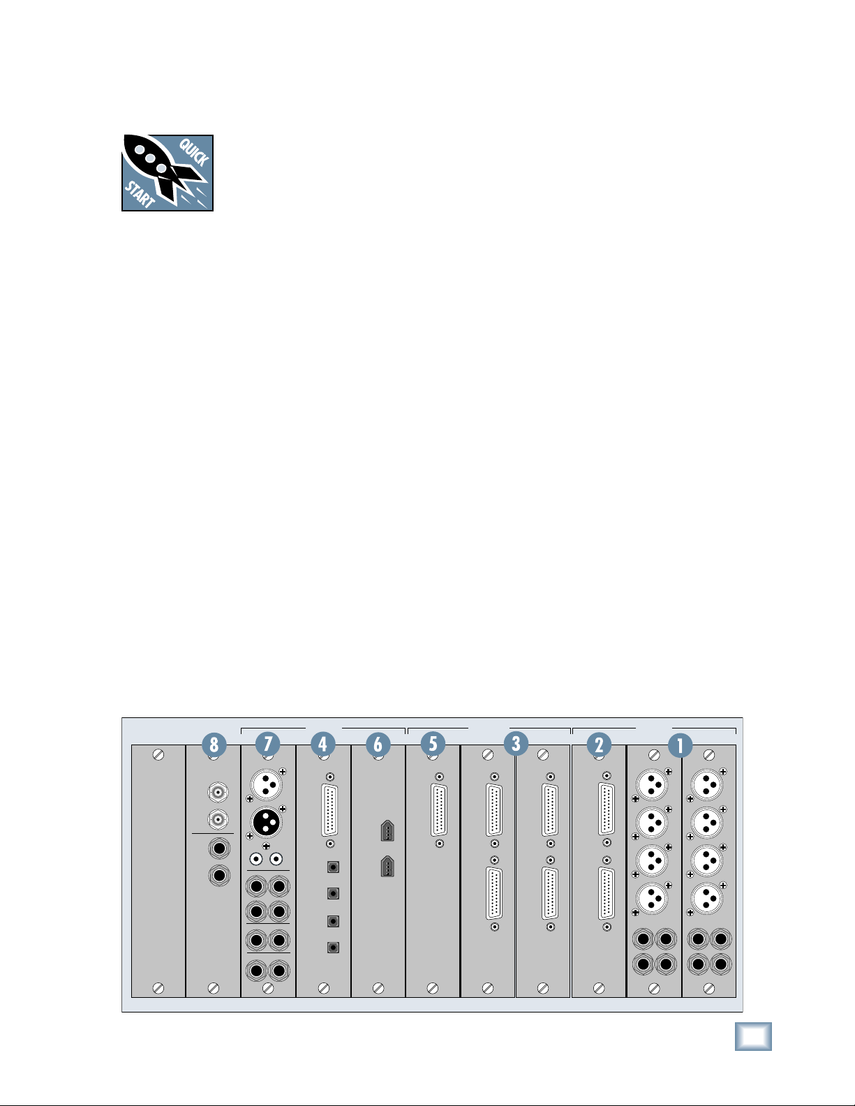
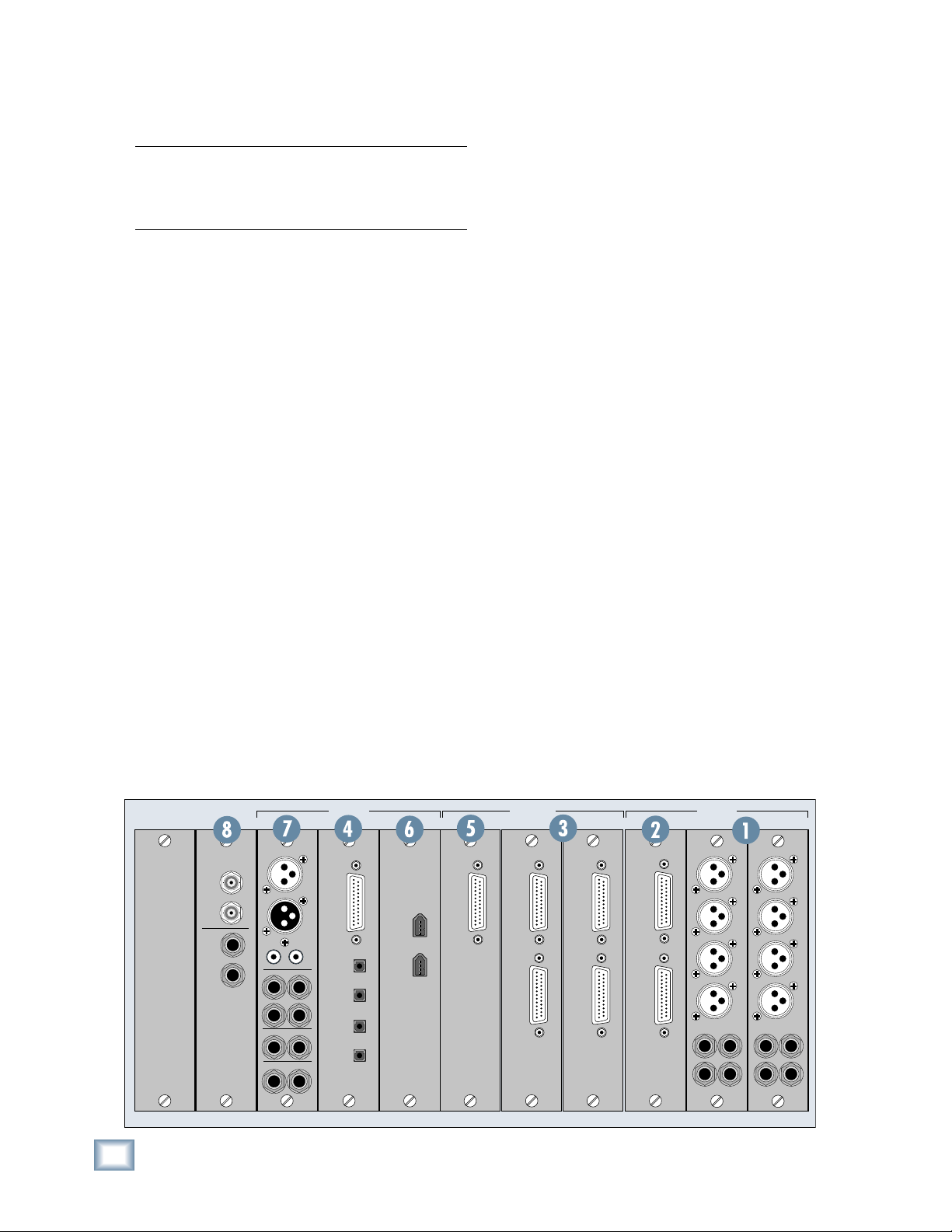
I/O Cards
1. MIC/LINE 4 CARD
This card has four female XLR balanced microphone inputs, and four 1/4" TRS balanced/unbalanced
line-level inputs, for a total of eight analog inputs.
Note that this card does not provide any outputs.
Each mic input provides an individual phantom
switch (+48 VDC), and a digitally controlled input
trim. All these controls are found in the I/O Confi gu-
ration window.
Each line input on the Mic/Line 4 card has a corresponding –10 dBv/+4 dBu jumper (J10-J13) on the
card that determines the input level reference point.
These jumpers come pre-installed from the factory
at a +4 dBu input level. However, if you have unbalanced or low line-level sources, you may choose to
remove these jumpers and set the input reference
to –10 dBv to better use the headroom of the mixer.
You can physically see these jumpers on the printed
circuit board of the card itself, and they can be
removed simply by pulling them off the card.
2. MIC/LINE 8 CARD
The Mic/Line 8 card has two female DB25 connectors, one for inputs and one for outputs. The
input connector accepts eight balanced analog inputs that can be switched between mic- or line-level
inputs. As with the Mic/Line 4 card, each mic input
provides a phantom power switch and a digitally
controlled input trim.
The output connector provides eight balanced linelevel outputs. These DB25 connectors use the TASCAM standard pinout for analog signal connections
(the same standard used on the analog cards for the
Mackie D8B and Hard Disk Recorder). If you are
connecting these to another device using the same
DB25 standard, you can use a DB25-to-DB25 audio
cable. Otherwise, you will need to use DB25 cables
that breakout to XLR, 1/4" TRS, or TT connectors.
SYNC C • SLOTSD • SLOT B • SLOTS A • SLOTS
WORD
CLOCK
SMPTE
OUT
SYNC CARD
IN
IN
OUT
MIX OUT CARD
IN
AES/EBU
OUT
IN
SPEAKERS
LR
LR
PHONES
12
MIX OUT
LR
SPDIF
TDIF
I/O
OUT
OPTICAL
IN A
A
IN B
B
OUT A
OUT B
FIRE CARDDIGITAL CARD
AES CARD
I/O
LINE CARD
OUT
IN
LINE CARD
OUT
IN
MIC/LINE 8 CARD
OUT
IN
Owner's Manual
MIC/LINE 4 CARD
1
2
3
4
5
7
MIC/LINE 4 CARD
1
2
3
4
5
6
7
8
6
8
9
Page 10
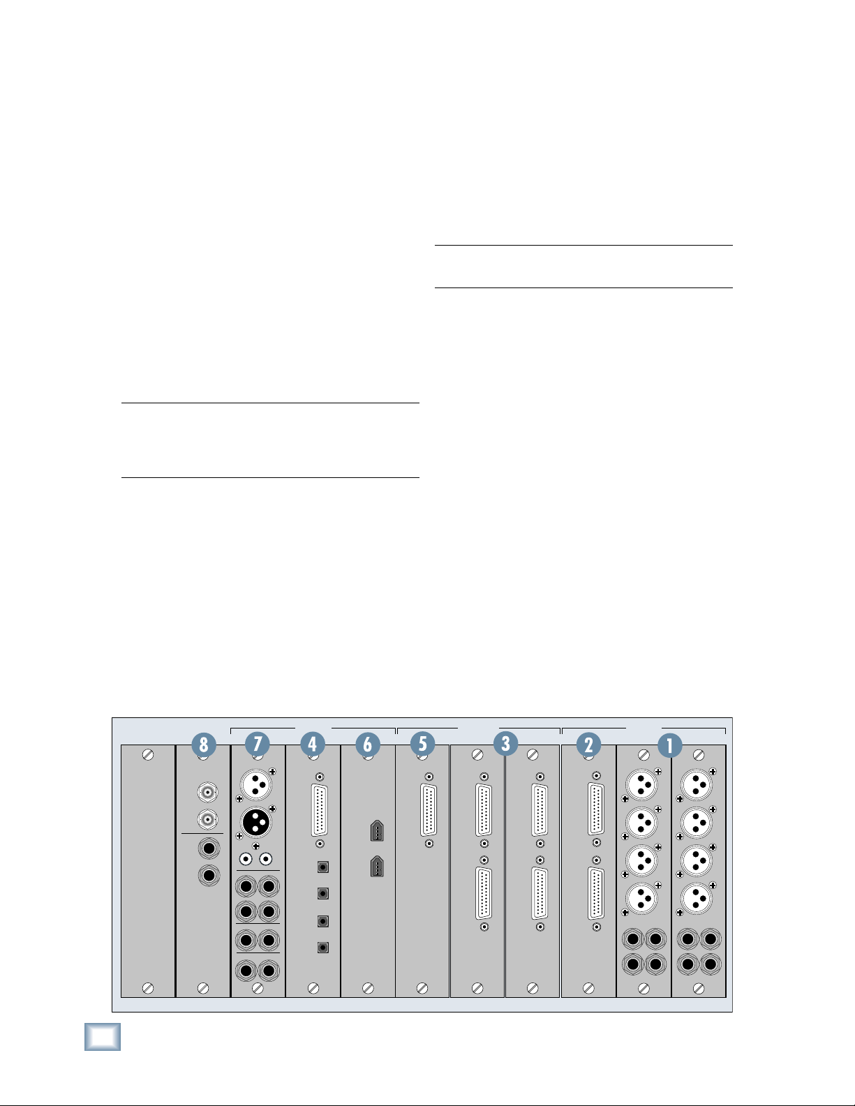
3. LINE CARD
The Line card has two female DB25 connectors.
One provides eight balanced line-level inputs, and
the other provides eight balanced line-level outputs.
They use the TASCAM standard pinout for analog
signal connections (the same standard used on the
analog cards for the Mackie D8B and Hard Disk
Recorder). If you are connecting these to another
device using the same DB25 standard, you can use
Digital X Bus
a DB25-to-DB25 audio cable. Otherwise, you will
need to use DB25 cables that breakout to XLR, 1/4"
TRS, or TT connectors.
Refer to Appendix B for a wiring diagram of these
connectors.
The Line card also has the –10 dBv/+4 dBu jumpers (described for the Mic/Line 4 card) that can be
left in place (for +4 dBu operation) or removed (for
–10 dBv operation).
Note:
The Mic/Line 4 card, Mic/Line 8 card, and
Line card all support analog-to-digital conversion at
sampling rates up to 192 kHz and word lengths of
either 16 or 24 bits.
At 44.1/48 kHz sample rates, each optical
TOSLINK connector provides either eight inputs
or eight outputs of digital audio. At 88.2/96 kHz
sample rates, the S/MUX protocol is used to provide
four channels of I/O on the “A” connectors, and four
channels of I/O on the “B” connectors. At 176.4/192
kHz sample rates, the S/MUX II protocol is used to
provide two channels of I/O on the “A” connectors
and two channels of I/O on the “B” connectors, for a
total of four inputs and outputs.
Note: The TDIF connector does not operate above
96 kHz.
5. AES/EBU CARD
The AES/EBU card has one DB25 connector,
providing eight channels of digital I/O in the
AES/EBU format.
The original AES/EBU specifi cation (IEC958 Type 1)
provides for carrying two channels of digital audio
at resolutions up to 24-bit at 48 kHz. When higher
sampling rates became possible, two methods were
developed to transmit digital audio at the higher
sample rates — double-fast and double-wide.
4. DIGITAL CARD
This card provides up to eight channels of digital
audio in two formats; TDIF-1 on a DB25 connector
and ADAT optical on four TOSLINK connectors.
The input type is selected in software (either
TDIF or ADAT). However, just because we can, we
made both sets of outputs alsways active for you
to use. This makes the Digital card a great format
converter between TDIF-1 and ADAT optical digital
devices.
SYNC C • SLOTSD • SLOT B • SLOTS A • SLOTS
FIRE CARDDIGITAL CARD
WORD
CLOCK
SMPTE
SYNC CARD
IN
OUT
IN
OUT
MIX OUT CARD
IN
AES/EBU
OUT
IN
SPEAKERS
LR
LR
PHONES
12
MIX OUT
LR
SPDIF
TDIF
I/O
OUT
OPTICAL
IN A
A
IN B
B
OUT A
OUT B
The double-fast method (also called single-wire)
clocks the digital I/O port at twice the speed to get
twice the information through, providing support for
resolutions up to 24-bit at 96 kHz.
The double-wide method (also called dual-wire)
transmits one channel of digital audio instead of two
channels through a single digital I/O port, again providing support for resolutions up to 24-bit at 96 kHz.
The AES/EBU card currently uses the double-fast
method, so eight channels of digital I/O are supported up to 192 kHz.
AES CARD
I/O
LINE CARD
OUT
IN
LINE CARD
OUT
IN
MIC/LINE 8 CARD
OUT
IN
MIC/LINE 4 CARD
1
2
3
4
5
7
6
8
MIC/LINE 4 CARD
1
2
3
4
5
7
6
8
10
X.200
Page 11

At sampling rates up to 48 kHz, two channels of
digital audio are transmitted on a single wire (one
3-pin XLR) at normal speed as specifi ed by the
AES/EBU standard.
At sampling rates of 88.2/96 kHz, two channels of
digital audio are transmitted on a single wire (one
3-pin XLR) at twice the normal speed (2x).
At sampling rates of 176.4/192 kHz, two channels
of digital audio are transmitted on a single wire (one
3-pin XLR) at four times the normal speed (4x).
Note: Check the owner’s manual for the device you
are connecting to the AES/EBU card, to fi nd out if
it supports the double-fast (or single-wire) method.
The AES/EBU card is wired the same way as the
Yamaha standard pinout for transmitting AES/EBU
over a 25-pin cable. Be very careful about specifying
these cables at a retailer or a cable manufacturer, as
there are several varieties of 25-pin “D-Sub” cables
and we want to be sure you get the correct ones!
Make sure to specify, “25-pin, D-Sub AES/EBU digital cable wired in the Yamaha standard.”
6. FIREWIRE CARD
The FireWire card uses the IEEE-1394 protocol
for connecting digital devices, and is compatible
with standard Mac and PC FireWire connections. It
currently provides 24 inputs and 24 outputs of digital audio at 48 kHz, and 8 inputs and 8 outputs at
96 kHz (with room for expansion as driver technology improves).
return, you can assign them to feed channels, buses,
the control room, or whatever you like.
S/PDIF IN and OUT
These are RCA-type connectors that send and
receive standard S/PDIF two-channel digital signals. The S/PDIF OUT follows whatever is selected
for the AES/EBU OUT in the Mix Out Card setup
window.
Touch the S/PDIF Input box in the Mix Out Card
setup window to use the S/PDIF IN instead of the
AES/EBU IN.
The default input numbers for the S/PDIF inputs
are 67 and 68 in any of the Input Source Assignment
drop-down boxes. As with the AES/EBU inputs, you
can route the S/PDIF inputs to feed channels, buses,
the control room, or whatever you like.
SPEAKERS A and B
These are two sets of stereo monitoring outputs
using 1/4" TRS jacks. They produce a line-level
analog signal that you can connect to the inputs of
the amplifi er powering your control room monitors
(or the inputs to your active studio monitors).
The NEAR button in the CONTROL ROOM section on the front of the console corresponds to the
“SPEAKER A” outputs, and the MAIN button corresponds to the “SPEAKER B” outputs.
The Control Room source is selected in the
CONTROL ROOM section of the console (press the
SETUP button in the CONTROL ROOM section for
more setup options).
Owner's Manual
It will appear as available patch points to any
audio software application that supports one of the
following formats:
• ASIO 2.0 (Windows XP/2000)
• WDM (Windows XP)
• Core Audio (Mac OS X)
7. MIX OUT Card
This provides several outputs (with the addition
of an AES/EBU and S/PDIF input), typically used
for control room monitoring, headphones, and main
outputs.
AES/EBU IN and OUT
These are XLR connectors that send and receive
standard AES/EBU two-channel digital signals. The
source for the AES/EBU OUT is selected in the Mix
Out Card setup window (Window > I/O Confi gura-
tion > Touch the Mix Out Card).
The default input numbers for the AES/EBU
inputs are 65 and 66 in any of the Input Source Assignment drop-down boxes. Even though the stereo
AES/EBU input is intended for a digital two track
The Control Room Left and Right outputs are assigned to the SPEAKER A and B outputs by default.
However, the source for the SPEAKER A and B
outputs can be reassigned in the I/O Confi guration
window (Windows > I/O Confi guration > Touch or
Select the Mix Out Card).
PHONES 1 and 2
These are stereo 1/4" TRS jacks that provide a
stereo output for headphones, or for connecting to a
headphone distribution box. These are assigned to the
Phones 1 and Phones 2 outputs by default, but can be
reassigned to virtually any input or output source.
The Phones 1 and 2 sources are selected in the
PHONES 1 or PHONES 2 section on the console
(press the SETUP button in the PHONES section for
more setup options).
MIX OUT
These are balanced 1/4" TRS jacks that provide a
line-level analog signal. These are assigned to the
left and right mix outputs by default, but can be reassigned to virtually any input or output source. Con-
Owner's Manual
11
Page 12
nect these outputs to the inputs of a 2-track recorder
for mixdown, or to the inputs of a power amplifi er to
drive a pair of speakers for the studio or whatever.
Note: Remember that the level for the Main L/R
Mix Out is always controlled by the Master Fader
on the console. The Control Room volume knob
does not affect this level.
Digital X Bus
8. SYNC CARD
The Sync card provides word clock synchronization in and out of the console on a pair of BNC
connectors, and SMPTE time code (also called
Longitudinal Time Code or LTC) in and out on a pair
of 1/4" jacks.
The word clock input is the only means to slave
the Digital X Bus sampling clock to an external
clock reference device, such as a “house sync” box
or a clock distribution system. The Digital X Bus
can lock to a word clock source running between
44.1 kHz to 192 kHz. The word clock input provides
a 75 ohm termination, which prevents the clock
signal from feeding back to the source and causing
synchronization problems.
If you are slaving the Digital X Bus off an external
word clock source, we do not recommend using the
word clock output of the console to distribute that
same clock signal to another digital device. There
will be a certain amount of propogation delay from
the input to the output, and this may cause a synchronization problem between your Digital X Bus
and other equipment. If you are using multiple digital devices in your studio, we recommend using a
word clock distribution device that can send a word
clock signal equally and evenly to all slave devices.
A note about clocking and sync:
The ADAT, AES/EBU, and SPDIF digital audio
specifi cations include the presence of a “clock refer-
ence signal” through the same physical connection
as the audio signals. This means that you can use
the Digital X Bus as a master clock source, and
lock several different digital devices to the digital
audio outputs of the console. You need to refer to
the external digital devices’ product documentation and/or manual(s) to learn how to lock external
devices off the ADAT, SPDIF, or AES/EBU outputs
of the Digital X Bus.
Remember that the Digital X Bus cannot slave to
any external source unless it is locked via the word
clock connection.
The SMPTE input can receive an LTC signal from
24 through 30fps (frames per second) and includes
support for “pull up” and “pull down” drop & nondrop frames rates.
When using the Digital X Bus with a SMPTE
input, we recommend locking the word clock of the
Digital X Bus to the same source that is generating the SMPTE output. This will ensure that the
console does not “drift” from your video or other
playback source.
The SMPTE output simply mirrors the SMPTE
input. Without a SMPTE input present, the SMPTE
output will not be active. Even though the Clock
Settings window has an “Internal” setting for the
time code source selection, the Digital X Bus does
not actually generate MTC or SMPTE signals at the
corresponding outputs.
Time code is also provided through MIDI time
code (MTC). SMPTE time code is more commonly
used in motion picture and broadcast applications.
12
X.200
SYNC C • SLOTSD • SLOT B • SLOTS A • SLOTS
WORD
CLOCK
SMPTE
SYNC CARD
IN
OUT
IN
OUT
MIX OUT CARD
IN
AES/EBU
OUT
IN
SPEAKERS
LR
LR
PHONES
12
MIX OUT
LR
SPDIF
TDIF
I/O
OUT
OPTICAL
IN A
A
IN B
B
OUT A
OUT B
FIRE CARDDIGITAL CARD
AES CARD
I/O
LINE CARD
OUT
IN
LINE CARD
OUT
IN
MIC/LINE 8 CARD
OUT
IN
MIC/LINE 4 CARD
1
2
3
4
5
7
MIC/LINE 4 CARD
1
2
3
4
5
6
7
8
6
8
Page 13
V 9
p 6
V 4.5
p 5
1100
W M
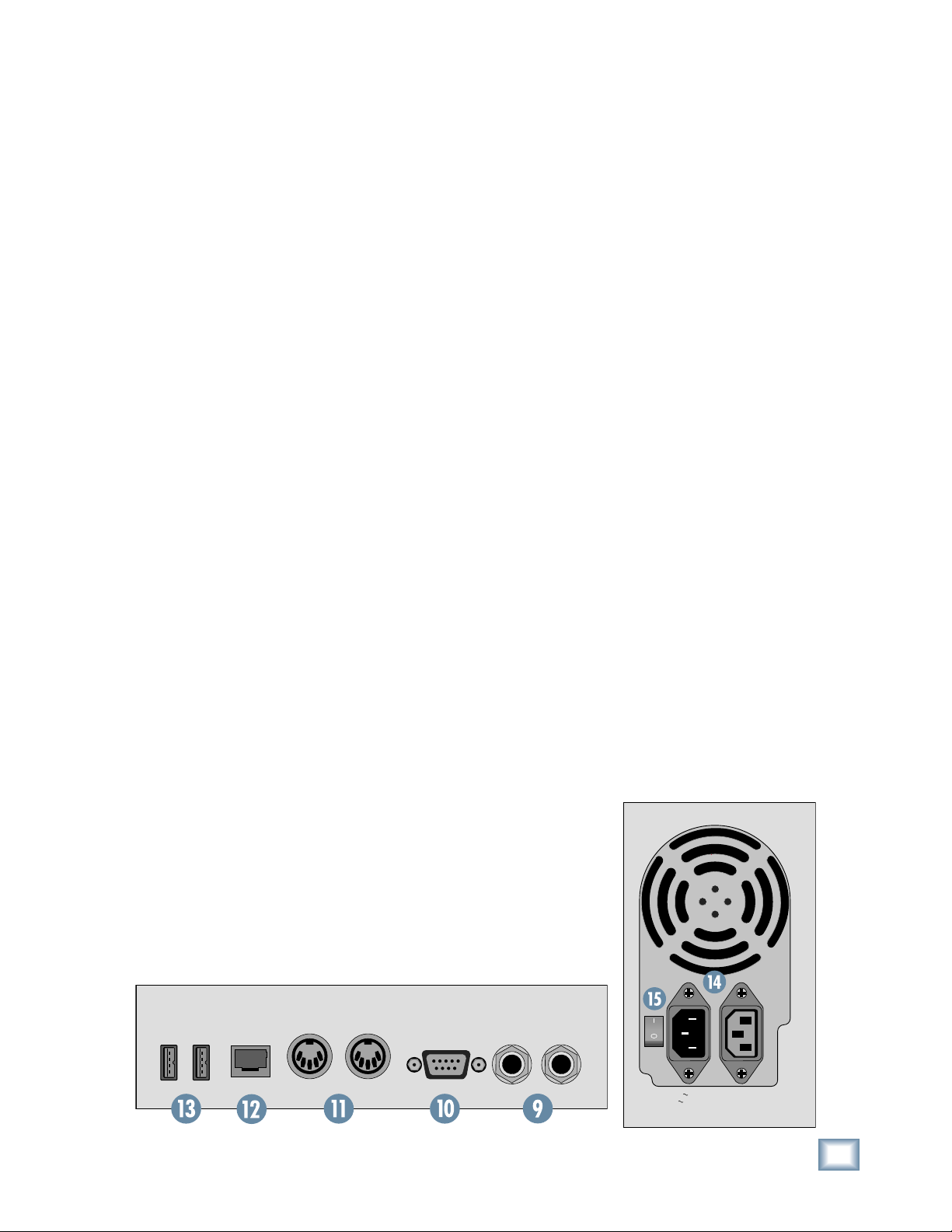
Other Connections
In addition to the cards in the card slots, there are
more connections to be made on the rear panel.
9. FOOT SWITCH 1 and 2
These two 1/4" TS jacks are provided for footswitch control of various functions. These functions
are assignable in the Windows > Setup window, and
include Talkback, Play/Stop, Next Marker, Previous
Marker, New Marker, and enabling/disabling the
Fader Swap function.
10. SERIAL 9 PIN
This DB9 connector is an RS-422 port that supports the Sony® 9-Pin device protocol. It is con-
fi gured to operate as a controller, so it should be
connected to a device (DEV) that is confi gured to
be controlled by a controller (CONT). This is used
primarily to transmit tape transport commands
from the Digital X Bus to a Sony 9-Pin compatible
recorder.
11. MIDI IN and OUT
These standard MIDI connectors (female 5-pin
DIN) can be used to send or receive MIDI Time
Code (MTC) and MIDI Machine Control (MMC)
when connecting to equipment with transport controls and a position display.
The MIDI connectors can also be used to control
your DAW application when the MIDI fader bank is
selected (up to eight channels).
You can turn MTC on and off in the Sync Card
setup window (Windows > I/O Confi guration and
touch the Sync card) by clicking the Generate MTC
box. You can select MTC as the timecode source in
the same setup window by clicking the TimeCode
Source dropdown box and selecting MIDI (MTC).
If you need additional MIDI ports, you can attach a third party USB MIDI interface to one of the
USB ports on the rear of the console, load the third
party drivers into the console, and use those ports
for whatever MIDI transmissions you want to use.
Please see “Connecting and Controlling a Digital
Audio Workstation” for complete details on supported USB MIDI Interfaces and how to confi gure them.
12. ETHERNET
This is a standard RJ45 telco connector. At the
time of this printing, the Ethernet connector is disabled. We reserve its use for future applications or
feature enhancements to the Digital X Bus.
13. USB
The two USB ports on the Digital X Bus can be used
to connect a USB equipped mouse, keyboard, or USB
memory stick (USB fl ash memory). See “More Con-
nections” just ahead to see how to connect more USB
devices, and a PS/2-style keyboard and mouse with a
6-pin miniDIN connector.
14. IEC Power Receptacle
There are two power receptacles on the Digital X
Bus, one to provide power to the Digital X Bus and the
other to connect to another device and provide power
to it. These are standard 3-prong IEC power connectors. Connect the detachable linecord (included with
your X.200) to the male power receptacle, and plug
the other end of the linecord into an AC outlet with
the correct voltage for your particular Digital X Bus.
To connect another device to the female IEC
power receptacle, you need a power cord with a
male IEC power connector on one end, and a female
IEC power connector on the other end. These can be
purchased at most electronic supply stores.
Owner's Manual
The Digital X Bus has many different MIDI functions — MMC, MTC, a MIDI Map, and the MIDI
Control Surface. It is up to you to route the MIDI
functions of the console to/from the physical MIDI
port using the MIDI Patch Bay in the Setup window
(Windows > Setup > MIDI).
USB ETHERNET SERIAL 9-PIN
MIDI
IN
MIDI
OUT
FOOT SWITCH
1 2
115V 9
amp 6
0Hz
230V 4.5
amp 5
0Hz
W M
ax
1100
Owner's Manual
13
Page 14
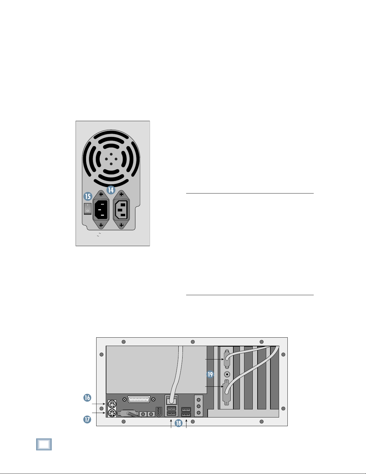
15. Power Switch
V 9
p 6
V 4.5
p 5
1100
W M
This one is self-explanatory. When the POWER
switch is turned ON, power is supplied to the Digital
X Bus and it boots up. When turning off the Digital
X Bus, you should select SHUTDOWN from the File
menu. At the end of the shutdown procedure, the
Digital X Bus lets you know when it is okay to turn
off the power switch.
Before turning on your Digital X Bus, please read
Digital X Bus
the “Power-up Procedure” section on page 55 of this
manual for complete step-by-step instructions.
115V 9
amp 6
0Hz
amp 5
1100
W M
0Hz
ax
230V 4.5
More Connections
16. Mouse
This 6-pin miniDIN connector is used to connect a
PS/2 style mouse.
17. Keyboard
This 6-pin miniDIN connector is used to connect a
PS/2 style keyboard.
18. USB
These are four additional USB ports for connecting more USB devices to the Digital X Bus. If you
are connecting a USB CD-ROM drive or a USB MIDI
interface, use one of these ports rather than the
USB ports on the rear panel (13).
19. Video Card
The video card has two connectors, one for each
touchscreen. The upper connector is a VGA-type
and connects to the left touchscreen, while the
lower connector is a DVI-type and connects to the
right touchscreen. You can use two video splitters to
connect two external displays, if desired.
Note: The fi rst production run of X.200s requires
that the external monitors be rotated 180º because the video signal is upside down. While
testing the touchscreen displays, we determined
that the clarity was better at the required viewing
angle if the touchscreen displays were mounted
upside down. If you are using external fl at-panel
LCD or plasma displays, this is not a problem.
However, conventional CRT-type displays generally will not work in this application.
There are even more connections available behind
the removable panel on the back of the Digital X
Bus. Use a small-headed Phillips screwdriver to remove the ten screws securing the panel to the chassis to access these additional connections, which we
call the Motherboard Access Area.
MOUSE
KEYBOARD
14
X.200
Also note that the “touch” function does not work
with an external display. This feature is built into the
actual touchscreen displays on the Digital X Bus.
VGA
DVI
USB PORTS
Page 15
Console Surface Controls
Owner's Manual
Channel Strip
The touchscreens are actually an extension of
the channel strips, so we'll begin by describing the
channel strip controls on the touchscreens.
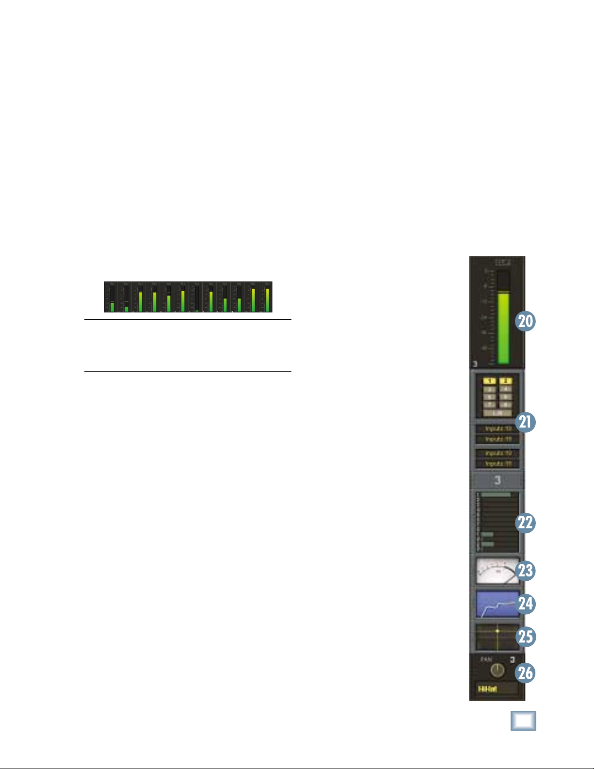
20. Meters
The meters indicate the signal strength at a point
in the signal path determined by the meters option
setting (Options > Meters).
Touching the meter section toggles the display
between a lower-resolution display of all the meters
(Channels 1-72 + Aux 1-12 + Bus 1-8 + L/R mix),
and a higher-resolution display of the meters for the
selected fader bank.
Tip: An easy way to change fader banks is to
toggle to all-meter display, then touch the section
in the meter display corresponding to the fader
bank you want to switch to.
21. Assign
This section of the channel strip indicates the
buses to which the channel is assigned, as well as
the input source for the channel, the direct output
assignment, and the pre- and post-insert assignments.
Touch the assign section of the channel strip to
open the ASSIGNS window. See "The Screens, The
Windows Menu, Assigns" for more info.
22. Auxes
The Auxes section indicates the Aux Send level
for Auxes 1-12 and the Aux Pan for Aux 9/10 (Cue
1) and Aux 11/12 (Cue 2).
Touch the Auxes section of the channel strip to
open the AUXES window. See "The Screens, The
Windows Menu, Auxes" for more info.
23. Dynamics
The analog-style VU meter indicates whether the
channel's compressor or gate are turned on (the
meter lights up when the gate or compressor are
turned on). When one of the dynamics processors
are on, the meter indicates the input signal strength
to the processors.
Touch the VU meter to open the DYNAMICS
window. See "The Screens, The Windows Menu,
Dynamics" for more info.
24. Equalizer
The small EQ window indicates whether the
channel's equalizer is turned on (the EQ window
lights up when the EQ is turned on). It also indicates the EQ setting for the channel in a graphic
display (amplitude vs. frequency).
Touch the EQ window to open the large EQUALIZER window. See "The Screens, The Windows Menu,
Equalizer" for more info.
25. Surround
The small surround window indicates
the surround panning for the channel,
Left/Right and Front/Back. In stereo
mode, it simply indicates the left/right
panning of the channel. In surround
mode, it indicates the surround pan
position.
Touch the surround window to open
the large SURROUND window. See "The
Screens, The Windows Menu, Surround"
for more info.
26. V-Pots
Just below the touchscreens are a row
of rotary controls called V-Pots, which
is short for virtual potentiometer. These
correspond to the rotary control that appears at the bottom of the touchscreens.
Unlike an analog console where a
rotary pot can control only one function,
a digital console allows you to assign a
V-Pot to many different functions.
Using the buttons to the right of the
touchscreens, you can assign the V-Pots
to control the following functions:
PAN L/R (Left/Right)
PAN F/B (Front/Back,
for surround sound)
AUX 1-8 Send
AUX 9/10 and 11/12 Send
AUX 9/10 and 11/12 PAN
Digital TRIM
LEVEL TO TAPE
Owner's Manual
15
Page 16

When one of the above buttons is selected (lit), all
24 V-Pots control that function for each of the 24 channels in the selected bank.
In addition, windows that contain adjustable parameters, like the Dynamics and EQ windows, have their
controls situated above the channel V-Pots, which
temporarily become controls for the parameters in
the window, overriding the V-Pot Assign selection. As
soon as the window is closed, V-Pot control returns to
Digital X Bus
whatever is selected in the V-Pot Assign section.
27. SELECT
• Selects a channel for editing.
• Double-pressing the SELECT button opens the
Dynamics and EQ windows for that channel.
• Pressing and holding the SELECT button opens
the Channel Settings window (Channel > Channel Settings) for that channel.
• Pressing and holding two SELECT buttons at
the same time opens the LINK SETUP window
for linking two channels.
28. ASSIGN
• The function of the ASSIGN button is deter-
mined by what is selected in the ASSIGN BUTTON SETUP area.
ASSIGN BUTTON
SETUP
REC
L - R
READ
WRITE
unassign channels from the L-R mix, and have
an overall view of the assigned to the L-R mix
for the selected bank.
• When READ is selected, the ASSIGN buttons
determine which channels playback automation.
If a channel has automation data associated
with it and it is not Read-enabled, automation
data will be ignored for that channel.
• When WRITE is selected, the ASSIGN buttons
determine which channels can be written to automation. A channel must be Write-enabled (and
the BYPASS button turned off in the AUTOMATION MODES section) in order to write automation data for that channel.
16
X.200
• When REC is selected, the ASSIGN buttons arm channels for
recording via MMC (MIDI Machine
Control). The ASSIGN button blinks
to indicate REC READY status.
When RECORD is activated in the
Transport section, the ASSIGN button lights steadily to indicate the
channel is recording.
• When L-R is selected, the ASSIGN buttons indicate the channels
that are assigned to the L-R mix
bus. This lets you quickly assign and
29. SOLO
• Pressing SOLO lets you hear
only the soloed channel in the
Control Room output (or the Left
and Right Mix if Mixdown solo
is enabled).
SELECT
• Select the solo mode in the
SOLO section: PFL, AFL, and
ASSIGN
Mixdown (see the SOLO section
description for more information
on solo modes).
• The CLEAR button in the SOLO
section blinks whenever any
SOLO
MUTE
channel is soloed. Press the
CLEAR button to turn off all
SOLO buttons.
• Soloing multiple channels is
accomplished by holding the
SHIFT key (on the console or
dB
10
5
keyboard) while pressing the
SOLO buttons on all desired
channels. Also, selected Solo
Latch in Windows > Setup >
U
5
Mix Options allows you select
multiple solos.
• Solo Isolate mode is accomplished by holding down the ALT
key (on the console or keyboard)
while pressing a channel’s SOLO
button. A solo isolated channel is always active on the solo
10
20
30
40
50
60
bus and therefore will not mute
when other channels are soloed.
The SOLO button blinks to indicate Solo Isolate mode.
Note: The CLEAR button does not turn off Solo
Isolated channels. You must hold down the ALT
key while pressing the SOLO button to turn off a
Solo Isolated channel.
30. MUTE
• Mutes the signal after the channel fader.
• Mute is prior to the L-R bus and Bus 1-8.
• Does not affect the Channel Out (Direct Out) or
pre-fader Aux send. It does affect the post-fader
Aux send.
31. Channel Fader
• Controls the signal level from the channel to the
bus or buses it is assigned to (typically the L-R
bus and the Bus 1-8 output).
• It does not affect the signal going to the Direct
Out (Channel Out) or the pre-fader Aux send.
Page 17

Control Room Section
Owner's Manual
Phones Section
The Control Room section is where you defi ne the
source for monitoring in your control room. Typically, you would use the Speaker 1 and Speaker 2
outputs on the Mix Card for control room monitoring, giving you the choice of near-fi eld and far-fi eld
monitoring through the two stereo line-level speaker outputs. This is confi gured in the I/O Confi gura-
tion window (Windows > I/O Confi guration).
Press the SETUP button [32] in the Control Room
section to open the Control Room Setup window.
• Select the output destination for the surround
sound stems. When you are mixing in surround
sound, you assign the eight bus outputs to the
I/O cards in this window.
• Select the input source for control room moni-
toring. There are four buttons labeled 1, 2,
Surround, and L-R. These correspond to the
buttons on the console labeled 1, 2, SUR, and LR [33]. The Custom Input Assigns 1 and 2 dropdown boxes are used to select virtually any
input source for the left and right control room
outputs. Select Surround to have your surround
sound stems pass through the Control Room
section. This allows you to have individual gain
controls for each stem (at the bottom of the
Control Room Setup window, using the console
V-Pots), and activate the surround calibration,
which sends pink noise to each surround output
to verify that each speaker is set to the same
relative volume.
CONTROL ROOM
1 2
• Select Near
(Speaker 1) or Main
(Speaker 2) control room outputs
[34/35].
SUR
L - R
• Adjust the listening level of the Near
or Main outputs with
MONO
the knob [36] in the
Control Room sec-
NEAR MAIN
tion on the console,
or the Near/Main
control in the Control Room Setup window. The DIM button
[37] allows you to
temporarily duck the
control room output
by a preset amount,
DIM SETUP
which you can set
in the Control Room
Setup window with a
range of off (–∞) to
0 dB.
The Phones section [38] allows you to select the
input source for the headphone outputs (Phones 1 and
2). Typically, you would select the C/R (Control Room)
button for the headphone source, but you can have
two custom sources confi gured in the Phones Setup
window. Press the SETUP button in the Phones 1 or
Phones 2 section to open the Phones Setup window.
• Click Copy Mix To Cue 1 or 2 to copy all the
channel fader settings to Cue Mix 1 (Aux 9-10)
or Cue Mix 2 (Aux 11-12). This is a quick way
to copy the Master L-R mix, including effects,
to the phones output.
• Click the Input Assign drop-down boxes to
select two custom input sources for each headphone output.
•
Adjust the headphone listening level with the
knobs [39] in the Phones 1 and Phones 2 sections.
Talkback Section
The Talkback section allows you to communicate
from the console to someone listening over the headphones. Press the SETUP button [40] in the Talkback section to open the TALKBACK SETUP window.
•
Select the source for the talkback function by
clicking the Source drop-down box. This can
be either the built-in talkback mic in the Talkback section, or a microphone connected to an
input card.
PHONES 2PHONES 1
1 2
SETUP C/R
TALK SETUP
Owner's Manual
1 2
SETUP C/R
SOLOTALK BACK
AFL
PFL CLEAR
MIX
DOWN
17
Page 18

• Click Talk to Phones 1 to send the talkback sig-
MACROS
SHIFT 1 2 3 4 5 6 7 8
nal to the Phones 1 output, and Talk to Phones
to send the talkback signal to the Phones 2
output.
• Adjust the talkback signal level with the Level
slider in the Talkback Setup window.
• Press the TALK button [41] in Talkback section to activate the Talkback function and send
Digital X Bus
the talkback signal to the selected headphone
outputs.
Solo Section
• The CLEAR button [45] blinks whenever a
channel is soloed. Press the CLEAR button to
clear all soloed channels. This is particularly
useful when working with solos across multiple
fader banks.
• Adjust the solo signal level with the knob [46]
in the Solo section.
Macros
The row of buttons just above the Transport
section is called Macros [47]. It consists of eight
buttons labeled 1-8 and a SHIFT button.
The Solo Section lets you select the solo mode,
clear all soloed channels, and adjust the solo level.
• Press MIXDOWN [42] to activate mixdown
soloing. This interrupts the L-R mix output with
the signal from the soloed channels.
• Use this mode whenever
you want the soloed channels to be the complete
mix—a rhythm section is a
good example of this.
• Mixdown solo is post-DSP and post-fader.
• Press AFL [43] to monitor the post-fader signal
in the Control Room output. This is a stereo bus
(post-pan) so soloed channels are heard in their
correct pan position.
• Press PFL [44] to monitor the pre-fader signal
in the Control Room output. This is pre-pan as
well, so the fader and Pan controls have no effect in PFL solo.
Note: If the channel fader is set low (less than
unity gain), soloing the channel in PFL mode
could result in a startling increase in volume.
Be forewarned!
• The Macros buttons provide instant access
to
16 frequently used windows or functions
(Buttons 1-8 and SHIFT+ Buttons1-8).
• Defi ne the window or function executed by each
button in the Macros Setup window (Windows >
Setup > Macros).
Transport Section
This section provides control for external recorder
transports, time display, snapshots, locates, and
loops.
48. Number buttons 0-9
• Used to numerically enter Snapshot, Locate,
and Loop points.
• When numeric buttons are used to enter data,
you must press ENTER to complete the action.
49. ENTER button
SOLOTALK BACK
AFL
PFL CLEAR
TALK SETUP
18
X.200
MIX
DOWN
• Initiates numeric changes that have been typed
into the Recall Snapshot or Recall Locate windows.
50. EDIT START
• Press this button to move the timeline cursor in
the Mix Editor and the position display to the
Edit In point.
51. END
• Press this button to move the timeline cursor in
the Mix Editor and the position display to the
Edit Out point.
Page 19

The Edit In and Edit Out points are used to copy,
cut, and paste sections of automation data in the
Mix Editor.
• Move the timeline cursor in the Mix Editor to
the point where you want to stop looping. Press
STORE [55] and then STOP [53].
Owner's Manual
To set the Edit In and Edit Out points:
• Move the timeline cursor in the Mix Editor to
the point where you want to start editing. Press
STORE and then EDIT START.
• Move the timeline cursor in the Mix Editor to
the point where you want to stop editing. Press
STORE and then END.
• You can also click and drag the Edit In and Edit
Out markers in the time bar in the Mix Editor
screen, or click and drag across the screen to
defi ne the start and stop points for an edit.
52. LOOP START
• Press this button to move the timeline cursor in
the Mix Editor and the position display to the
Loop In point.
53. STOP
• Press this button to move the timeline cursor in
the Mix Editor and the position display to the
Loop Out point.
54. ON
• Press this button to start loop playback from
the points defi ned by the Loop In and Loop Out
points in the Mix Editor.
To set the Loop Start and Stop points:
• Move the timeline cursor in the Mix Editor to
the point where you want to start looping. Press
STORE [55] and then LOOP START [52].
• You can also click and drag the Loop In and
Loop Out markers in the time bar in the Mix
Editor screen.
56. SNAPSHOT
• To recall a snapshot, press SNAPSHOT, then
enter a snapshot number using the number buttons, then press ENTER [49].
• To store a snapshot, with SNAPSHOT lit press
STORE [55], then enter the snapshot number
you want to use to store the console settings,
then press ENTER [49].
You can also open the Snapshot window (Win-
•
dows > Snapshots) to store and recall snapshots.
57. LOCATE
• To recall a locate point (moves the timeline cursor to the locate point in the Mix Editor), press
LOCATE, then enter the locate number using
the number buttons, then press ENTER [49].
• To store a locate point, move the timeline cursor in the Mix Editor to the position you want
to put the locate point. With LOCATE lit, press
STORE [55], then enter the locate number you
want to use to mark the position, then press
ENTER [49].
• To reset a locate point to a new location, move
the timeline cursor in the Mix Editor to the new
location. With LOCATE lit, press SET [58].
• You can also recall and store locate points in
the Locator window (Windows > Locator).
EDIT
START
END
SNAP
SHOT
LOCATE
REWIND FAST FWD PLAYSTOP RECORD
7 8 9
4 5 6
1 2
STORE SET ENTER
0
3
LOOP
START
STOP
ON
SCRUB
Owner's Manual
19
Page 20

58. SET
• To move the timeline cursor to a new position
in the Mix Editor, with LOCATE [57] lit, press
SET, then enter the time you want to move the
cursor to using the number buttons, then press
ENTER [49].
Transport Controls
These buttons control external devices that
Digital X Bus
respond to MIDI Machine Control (MMC). MMC is
transmitted from the MIDI OUT port on the rear panel of the Digital X Bus to MMC-compatible devices.
Transport controls can be programmed to export
specifi c MIDI messages other than standard MMC
protocol. See MIDI Mapping for more details.
Note: MMC is not bidirectional. The Digital X
Bus sends out MMC commands to your tape
recorder(s), but if you arm tracks or operate transport controls from the tape recorders, the activity is not transmitted back to the Digital X Bus
via MMC. You can, however, press Play on your
recorder and, as soon as time code is received, the
Digital X Bus reverts to PLAY mode.
61. STOP
• Stops external machines and the time code
display at the current position.
62. PLAY
• Engages external machine and time code display to play at normal speed from the current
location.
63. RECORD
• Engages Master record function on external
machines.
• Must be pressed with PLAY to engage record
mode unless One Button Record is active. One
Button Record allows punching into record
mode without hitting PLAY (see Windows >
Setup > Mix Options).
64. SCRUB
• Engages the jog wheel to advance external machines forward or backward with single-frame
accuracy when using MMC.
59. REWIND
• Engages external machine and the time code
display to fast rewind.
60. FAST FWD
• Engages external machine and the time code
display to fast forward.
EDIT
START
END
SNAP
SHOT
LOCATE
7 8 9
4 5 6
1 2
STORE SET ENTER
0
3
LOOP
START
STOP
ON
20
REWIND FAST FWD PLAYSTOP RECORD
SCRUB
X.200
Page 21

The Screens
Owner's Manual
The touchscreens provide an elegant user interface for accessing and controlling the signals as
they are routed through the Digital X Bus.
Overview
Before getting into the details of all the menu
items and windows that are accessible on-screen,
it’s worthwhile to mention at this point that a
number of shortcuts are built into the touchscreen
interface to quickly get to where you want to be.
Meters and Switching Banks
Touching the meters at the top of the screen
toggles between a view of just the meters for the
selected bank, or a total view of all 92 meters. The
bank view provides a magnifi ed view with clipping
indicators, while the total view allows you to see
what is happening with all the channels, all at once.
Accessing Windows
In addition, specifi c windows pertaining to a chan-
nel can be opened by simply touching that area in
the channel strip.
Note: Touching an area on the touchscreen sometimes results in a different action than clicking
the same area with the mouse.
For example:
• Touch the bus assign area just below the me-
ters on a channel strip to open the ASSIGNS
window, which is also accessible by selecting
Windows > Assigns.
Click in the bus assign area to turn the individ-
ual bus assignments on and off, and to change
input, insert, and direct output assignments.
• Touch the auxes section just below the channel
number to open the AUXES window.
Click in the auxes section to adjust the indi-
vidual aux send levels (and cue panning).
Touching the meter for a specifi c channel or
group of channels while in the total view causes
the Digital X Bus to switch to the bank in which the
channel or channels belong, while switching the
meter view to the view for that bank. This allows
you to quickly switch from one bank to another
from the touchscreen.
• Touch the VU meter to open the Dynamics window.
• Touch the EQ graphic display to open the Equalizer window.
Click the EQ graphic display to turn the EQ on
and off.
• Touch the Panning graphic display to open the
Surround window.
Click in the Panning graphic display to adjust
the surround position.
Owner's Manual
21
Page 22

Channel Layout Reconfi guration
The File Menu
The channel number provides access to a hidden
menu that allows you to move channel strips around
and to lock a channel strip so it is visible no matter
what fader bank you have selected.
• Right-click on the channel number to open the
channel assignment menu (or Alt+Touch the
Digital X Bus
number).
• Select “Lock Channel” to lock the
channel in place so it is visible
with any fader bank selected.
Select “Lock Channel” again to
unlock it. (Alternatively, hold
down the ALT button or ALT key
and press a channel SELECT button to lock and unlock a channel.)
• Select “Reset All” to change all
the channel strips back to their
original confi guration (numerically sequential).
• Select “Reset Bank” to change all the chan-
nel strips in the currently selected fader bank
back to their original confi guration (numerically
sequential).
• Use the Channels, Masters, Groups, and MIDI
submenus to reassign the channel strip position
to a different channel.
Contains:
New Session (Ctrl+N)
Open Session (Ctrl+O)
Save Session (Ctrl+S)
Save Session As… (Ctrl+Shift+S)
Import D8B Session
Save As Template…
Open File Manager
Launch Executable (.EXE)
Install Packages…
Shutdown (Ctrl+Q)
New Session (Ctrl+N)
• Press Ctrl+N on the keyboard, or touch File and
then New Session.
• This opens a window that asks if you want to
save changes to the current project fi rst. Select
“Yes,” “No,” or “Cancel.”
• The Select Template window opens, which al-
lows you select a pre-saved template for your
new project. Select a template if you wish and
touch “OK,” or touch “Empty” to open the default new project template.
• Select “Master Fader” to assign the Master
Fader to the channel strip position.
Fader Swap
The Fader Swap button (located next to the time
code display in the upper-right corner of the touchscreen) causes the faders to take on the function
of the V-Pots, allowing more precise control over
a V-Pot setting. If it is a level function, fader-down
is minimum and fader-up is maximum. If it is a
pan function, the fader is centered when the pan is
centered.
For example, a good use of the Fader Swap function is when you are doing a frequency sweep in the
EQ. Using a channel fader to control this parameter
gives you more physical space and throw with which
to make your setting that much more accurate.
D D D D D D D D D D D
This chapter provides a quick (well, maybe not
so quick, but certainly helpful) rundown of all the
menus and screens accessible from the menu bar at
the top of the touchscreen.
Open Session (Ctrl+O)
• Press Ctrl+O on the keyboard, or touch File and
then Open Session.
22
X.200
Page 23

• Use this to open a pre-existing session fi le.
• As soon as the session is opened, the faders
and all other parameters move to their proper
settings for the current time code location.
Save Session (Ctrl+S)
• Press Ctrl+S on the keyboard, or touch File and
then Save Session.
• Save the current session to its assigned location on the hard drive.
• You can turn on the Digital X Bus Smart Save
feature (Windows > Setup), which automatically saves your session every XX minutes. If
you have Smart Save turned off, be sure to save
your session often to protect yourself from lost
work—stuff happens.
Save Session As… (Ctrl+Shift+S)
• Press Ctrl+Shift+S on the keyboard, or touch
File and then Save Session As…
• Opens the Save Session As window. Enter a
new name for the session using the keyboard,
or touch the Name box to open the on-screen
keyboard.
Import D8B Session
Owner's Manual
• For Digital 8•Bus users, converts a D8B session fi le to a Digital X Bus session.
Note: This feature imports channel fader, mute,
and pan settings for channels 1-72, and the aux
send levels/pans for auxes 1-12, along with the
master aux sends ands buses 1-8 levels. Channel
EQ, compressor, and gate settings are also imported into the Digital X Bus session, but because
the algorithms for the EQ and dynamics sections
are different in the Digital X Bus, the sound will
be somewhat different on the Digital X Bus than it
was on the D8B.
• Touch Save to save the session to the default
session folder, or you can navigate to another
folder at the top of the Save Session As window.
• An extremely useful feature for saving variations of a session.
• Lets the current session be saved under a new
name, leaving the original fi le untouched from
that point on.
• Good for backing up session data under a new
fi le name, or to an external USB Flash drive.
Save As Template…
All new sessions are based on a template. A
template is stored separately from sessions, but
can be updated at any point with the current static
mix levels, setup parameters, and channel settings
of any given mix. Simply select Save As Template
under the File menu.
• Allows you create a new template. For example,
the default template sets all the faders down, so
you can create a new template where the faders
are all set to unity.
Owner's Manual
23
Page 24

Open File Manager
Digital X Bus
Install Packages…
• Gives you direct access to fi le management
features such as copying or moving fi les and
folders, deleting fi les, and creating new folders.
• Rename fi les.
• Allows you to copy and move fi les from the
internal drive to an external drive for backup.
Note: The destination drive or folder must be
opened and displaying its contents for proper
placement to occur. You can't drag and drop fi les
in the File Manager window. You must use the
Move and Copy arrows.
Launch Executable (.EXE)
• Opens the Package Installer window.
• Scans any attached USB peripheral for a
Mackie-packaged installation fi le.
• Reports the status of all installers detected.
• Used for all Mackie-approved plug-in and soft-
ware installations.
Shutdown (Ctrl+Q)
• Press Ctrl+Q on the keyboard, or touch File and
then Shutdown.
The Digital X Bus asks you if you want to save
•
the current session before shutting down. Select
“Yes” to save the session, “No” to continue shutting down without saving the session, or “Cancel” to continue working in the current session.
• Opens the Launch Installer window, which allows you to browse to an executable fi le (.exe),
a link to an executable (.lnk), or installer fi le on
the hard drive.
•
Used to install 3rd-party plug-ins, run third party
authorizer applications, or MIDI interface drivers.
24
X.200
• In the Shutdown window, select “Shutdown”
to close the Digital X Bus software, “Restart”
to reboot the operating system, or “Cancel” to
continue working in the current session.
• After shutting down, you will notice the mixer
will turn off and the screens will shut off. Once
that has happened, you need to turn off the
power switch on the Digital X Bus. You must
turn the switch to the off position before you
can turn it back on to restart the console.
Page 25

The Edit Menu
Contains:
Undo (Ctrl+Z)
Redo (Ctrl+Shift+Z)
Cut (Ctrl+X)
Copy (Ctrl+C)
Copy Filtered… (Ctrl+Shift+C)
Paste (Ctrl+V)
Modify Levels…
Insert Global Time…
Delete Global Time…
Clear Automation
History List (Ctrl+H)
Clear History
Copy Mix To Bus
Undo (Ctrl+Z)
• Reverses an action. If you’ve made a bad
automation pass, cut something you didn’t re-
ally want to cut, pasted somewhere you didn’t
want to paste, etc., simply select Undo (or type
Ctrl+Z on the keyboard) and the Digital X Bus
reverts to its previous state.
• Selecting Undo multiple times steps back
through the history list (list of actions taken),
all the way back to the top level (starting
point), if necessary. Open the History List
(Ctrl+H) to check it out.
Redo (Ctrl+Shift+Z)
• Reverses an Undo. If you’ve undone an action,
or set of actions, you might determine that your
original guess was best, and want to return to
actions you removed.
• Redo is a multilevel command, like Undo, so
multiple redo commands retrace your steps
through any undone actions in reverse order.
Cut (Ctrl+X)
• Copies all the selected channel’s parameter data
to the clipboard and sets the channel’s param-
eters to their default settings.
• The data on the clipboard can be pasted to
another channel.
Copy Filtered… (Ctrl+Shift+C)
Owner's Manual
• Opens the COPY FILTERED window. This allows you to select the individual channel parameter data to copy to the clipboard.
These parameters include:
Fader Dynamics
Mute Buses
Pan Phase
Auxes Surround
EQs Assigns
• The selected channels parameter settings are
not changed.
• The data on the clipboard can be pasted to an-
other channel. Only the selected parameters are
pasted into the new channel. The unselected
parameters are left intact.
• You can use the Undo command (Ctrl+Z) to
undo a Copy Filtered command.
Paste (Ctrl+V)
• Replaces the parameters in a selected channel
with the data in the clipboard.
• The data on the clipboard remains intact, so it
can be pasted to multiple channels.
• You can use the Undo command (Ctrl+Z) to
undo a Copy command.
Modify Levels…
• Opens the MODIFY LEVELS window. Use this
control to modify individual parameters for the
selected channel(s).
• You can use the Undo command (Ctrl+Z) to
undo a Cut command.
Copy (Ctrl+C)
• Copies all the selected channel’s parameter
data to the clipboard and leaves all the selected
channel’s parameters intact.
• The data on the clipboard can be pasted to
another channel.
• You can use the Undo command (Ctrl+Z) to
undo a Copy command.
Owner's Manual
25
Page 26

• Choose the type of parameter from the top pulldown box.
Digital X Bus
• Selecting Insert Global Time in the Edit menu
opens a window with settings for the insert
start point and length of time inserted.
Delete Global Time…
• With the Mix Editor open, this feature globally
deletes a region of data change at the selected
start point (on all channels for all data).
• Choose the action from Set, Trim, Min, and
Max.
Set moves the selected parameter setting to the
specifi ed value for all selected channels.
Trim adds or subtracts the specifi ed value from
the selected parameter for all selected channels.
Min limits the minimum value for the selected
parameter, and applies it to all selected channels.
Max limits the maximum value for the selected
parameter, and applies it to all selected channels.
• Selecting Delete Global Time in the Edit menu
opens a window with settings for the deletion
start point and length of time deleted.
Clear Automation
• Removes all automation data globally for the
selected channels and the selected categories.
• The Mix Editor window must be closed to use
the Clear Automation command.
• This action can be undone as long as it remains
in the History List.
• Plug-in automation is cleared by removing the
plug-in from the Effects Rack (Ctrl+8).
History List (Ctrl+H)
• The History List window lists actions taken in
the Mix Editor. In addition, Automation Passes,
Clear Automation, Delete Global Time, Insert
Global Time, Delete Events, and Modify Levels
commands are logged as single list items. Each
of these actions is available for Undo, as long as
they remain on the History List.
Insert Global Time…
• With the Mix Editor open, this feature globally
inserts a region of no data change at the selected start point (on all channels for all data).
26
X.200
Page 27

• Using this list, it is possible to regress to any
point in the mix. If at some point things went
in the wrong direction, it is easy to go back to
where the mix was on the right track.
• Highlight any item in the list to deactivate all
forthcoming listed actions. When the mix is
played, no actions listed below the selected
event will occur.
• If an event is selected in the list and then a
change is made in the Mix Editor, all events following the selection will be replaced by the new
event.
• Use the Undo command from the Edit menu
(Ctrl+Z) to regress through the History List
steps one at a time.
• Use the Clear History command from the Edit
menu to remove all events from the History
List. This action cannot be undone.
Clear History
• Removes all items from the History window.
• This action cannot be undone.
Owner's Manual
The Channel Menu
The Channel menu contains:
Channel Settings (Ctrl+B)
Channel Presets
Setup Groups (Ctrl+G)
Un-Group
Link Channels… (Ctrl+L)
UnLink Channels (Ctrl+U)
Faders to Unity (Ctrl+])
Faders to Off (Ctrl+[)
Adjust Channel Delay…
Reset Channel Delay…
Reset Selected Channels
Select Fader Bank (Alt+A)
Select All Faders (Alt+Shift+A)
Channel Settings (Ctrl+B)
Copy Mix To Bus
• Copies the current L/R mix to a pair of buses.
• Selections include Bus 1 and 2, Bus 3 and 4,
Bus 5 and 6, or Bus 7 and 8.
• Check “Unassign from LR Mix” to remove the
selected channels from the L/R Mix and copy to
the selected bus pair.
• Allows for quick and easy setting of global
channel parameters.
• Change the channel name.
• Easily set groups.
• Solo isolate channels.
• Quickly set channel links.
Channel Presets
• Allows you to save and open preset channel
parameter settings.
• Click New to create a new channel preset. Enter
the new name using the keyboard or on-screen
keyboard.
Owner's Manual
27
Page 28

• Click Save to update the channel preset with
the current selected channel’s settings. All the
channel parameters (EQ, Dynamics, and DSP
Insert patch points) are saved as well.
• Highlight the desired preset and click Load to
copy the preset settings to the selected channel.
• Click the Preview box to observe the channel
preset settings on the selected channel before
Digital X Bus
clicking Load.
• Click Change Folder to organize channels into
logical groups: band name, instrument type,
singers, drums, guitars, etc.
Setup Groups (Ctrl+G)
• Provides a convenient way to group faders for
control by a group master fader in the GROUPS
fader bank.
Simply select the group to which you want to as-
•
sign channels, and then select those channels on
the console.
• This does not override any previous group settings outside the selected channels; however, a
channel can only be assigned to one group. The
most current group selection does override a
previous channel group assignment.
• This feature provides a way to add faders to an
already existing group.
Un-Group
• Provides an easy way to remove channels from
a previously established group.
Select some or all of the grouped channels to re-
•
move the selected channel(s) from group status.
Link Channels… (Ctrl+L)
• Channel linking allow you to control a pair of
channels at the same time. All channel parameters can be linked, or just selected parameters.
For instance, in many cases only the faders
need to be linked; all other parameters should
remain independent for the individual track.
• Any channel can be linked to any other channel.
• Linking allows a stereo channel to be input on
two channels and controlled as a pair of consecutive faders.
To link a pair of channels, select the left channel
•
of an adjacent pair and choose Link Channels…
from the Channel menu, or press Ctrl+L on the
keyboard. The Link Setup window appears.
• To link a pair of non-adjacent channels, select
the fi rst channel, then SHIFT+SELECT the
second one, then select Link Channels from the
Channel menu.
• Select the parameters that you want linked
between the channels. All checked parameters
are adjusted together for both linked channels.
• Select how you want the channels linked. In
this case, we are linking channel 1 and 2.
Check “Preserve Ch. 1’s values” to copy channel
1’s parameters over to channel 2.
Check “Preserve Ch. 2’s values” to copy channel
2’s parameters over to channel 1.
• Click the Link button to link the channels you
have selected, or click Cancel to cancel the linking process.
• To link a pair of channels from the control surface, press and hold the SELECT buttons of the
two adjacent channels you wish to link. This
opens the Link Setup window.
• Select Pan Inverse to have the pans linked
inversely. This means that rotating the pan
control on one channel causes the pan control
on the linked channel to rotate in the opposite
direction.
28
X.200
UnLink Channels (Ctrl+U)
• Removes a link between channels.
• Select a linked channel and then select Unlink
Channels in the Channels menu.
Faders to Unity (Ctrl+])
• Sets the selected channel faders to unity.
Affects faders only (including Master L/R faders).
•
Does not affect any other channel parameters.
Page 29

Faders to Off (Ctrl+[)
• Sets the selected channel faders to off.
Affects faders only (including Master L/R faders).
•
Does not affect any other channel parameters.
Adjust Channel Delay…
• This features provides a means to shift channels in time, relative to each other.
• Select the channels that will remain at the
original position; all unselected channels will
be offset by the selected number of samples
(±255).
• Use to compensate for phase and timing discrepancies in a synchronization scenario or any
multitrack playback/record device setup.
• For example, if you place a plug-in with 100
samples of delay on a channel, the audio will be
behind the rest of the channels by that amount.
To compensate, you would select the channel,
choose “Adjust Channel Delay” and enter a
value of 100.
• The Channel Delay control appears in the Assign window for the selected channel.
Select Fader Bank (Alt+A)
Owner's Manual
• Selects all 24 channels in the currently selected
fader bank for clipboard, automation, and other
operations pertaining to multiple channel modifi cations.
Select All Faders (Alt+Shift+A)
• Selects all 118 channels in fi ve fader banks (not
counting MIDI) for clipboard, automation, and
other operations pertaining to multiple channel
modifi cations.
The Options Menu
The Options menu contains:
Solo Latch
Automation
Transport
Meters
DAW Emulation Mode
Faders To Tape
Route to Bank
Bank to Outputs
Solo Latch
• When Solo Latch is selected (a checkmark ap-
pears next to Solo Latch in the Options menu),
you can solo more than one channel at a time.
• When Solo Latch is off, only one channel may
be soloed at a time.
• You can manually solo more than one channel
when Solo Latch is off by pressing the Shift key
while soloing multiple channels.
Reset Channel Delay…
• This resets the delay to 0 ms on the selected
channels.
• To reset all channels, Select All Faders
(Alt+Shift+A), then select Reset Channel Delay.
Reset Selected Channels
• Resets the selected channels to their default
settings (L/R assign, Level to Tape and Digital
Trim to 0 dB, EQ on and fl at, Auxes off, Pan
centered, Fader off, Gate and Compressor off
and at default settings).
Automation Submenu
Bypass
• Selecting this option mirrors the BYPASS button on the console.
• When Bypass is selected, automation data is
neither recorded nor played back.
• When Bypass is not selected, all write-selected
parameter adjustments are written into automation data and referenced to time code.
Trim
• Selecting Trim mirrors the TRIM button on the
console.
• Sets all faders to unity position (when “Trim
From Unity” is selected in the Windows < Automation window) and assigns all parameter controls (except mutes) to globally add or subtract
from existing settings and recorded moves.
Owner's Manual
29
Page 30

• This is perfect for raising or lowering a complete set of automation moves. For example, if
the vocal track is perfectly crafted and structured, yet the entire track needs to come up a
couple of dB in the mix, fear not. Select Trim,
start time code, enter WRITE mode and, with
one move, increase the vocal track fader 2 dB
throughout the duration of the pass.
Latch
Digital X Bus
• This determines the action of overwriting automation data during a pass.
Write Flyback
• This determines what happens to the parameter
levels upon punch-out of automation record.
• When Write Flyback is selected (a checkmark
appears next to Write Flyback in the Automation submenu), each parameter recorded into
automation returns to its previously adjusted
status at the end of a record pass. A track that
was off for an entire arrangement snaps back to
off, after the level is increased, when punched
out of write-record.
• When Latch is selected (a checkmark appears
next to Latch in the Automation submenu), automation data for the selected parameter begins
to be overwritten as soon as the parameter’s
control is adjusted and continues to be overwritten throughout a pass, even if the parameter’s
control ceases to change.
• When Latch is off, automation data for the
selected parameter begins to be overwritten as
soon as the parameter’s control is adjusted, but
as soon as the parameter’s control stops chang-
ing, the subsequent automation data is left
intact.
Faders
• This readies the automation computer to record
all fader movements for any write-enabled channel.
Mutes
• This readies the automation computer to record
all mute activity for any write-enabled channel.
Pans
• This readies the automation computer to record
all pan movements for any write-enabled channel.
• All surround pans are recorded as well as L/R
positioning. However, surround output, depth of
center, and LFE Level are not written with this
selection (use Other/All to write automation for
these parameters).
Other
• When Write Flyback is off, parameter adjustments in automation remain at their last
user-adjusted setting, even after the end of the
automation pass.
Transport Submenu
Use Pre-Roll
• Sets the playback cursor a specifi ed amount
ahead of the locate point.
• The amount of Pre-roll is set in the Windows >
Setup > Mix Options window.
• Pre-roll is used to provide a set time period
for all synchronized device transports to lock
together.
• Ideally, Pre-roll is equal to the sync-lock time
for the recording system’s transports so that
synchronized playback is a reality by the time
the devices roll past the locate position.
• Pre-roll is also useful when you are punching
in a solo or voice overdub and want to give the
talen some extra lead-in time to prepare recording their part(s).
Record Safe
• When Record Safe is selected, the channel
RECORD buttons will not engage. However,
automation data can still be written.
One Button Record
• When this option selected, record mode is activated by pressing the RECORD button in the
control surface’s transport section.
• Sets the automation computer to record all parameter changes for the write-enabled channels,
other than the individually selectable Faders,
Mutes, and Pans.
30
X.200
• When One Button Record is not selected, the
PLAY button must be held down while pressing
the RECORD button to engage record mode.
• To punch out of record mode, simply press
PLAY, STOP, REWIND, or FAST FWD.
• One Button Record only affects the punch-in
procedure. The punch-out procedure is the same
regardless of the status of One Button Record
(hit any other transport button to punch out).
Page 31

AutoPlay
• When AutoPlay is selected, playback starts
automatically when you jump to a locate point.
• This is handy when you are jumping from one
locate point to another, listening for something
in particular.
Dynamics Submenu
Owner's Manual
These three options allow you to change what is
being displayed in the VU meter in the dynamics
section of the channel strip. These options have no
effect on the meter bridge at the top of the screen.
In
Meters Submenu
Show All Meters
• Select this option to display all 94 meters (including the L/R mix).
• Touch the meter bridge in the display to toggle
between showing the 24 meters in the currently
selected bank and all meters.
Input
• The meters display the signal at the input, prior
to any controls on the Digital X Bus.
Pre-Fader
• The meters display the signal just prior to the
fader, post- Digital Trim, EQ, Compressor, Gate,
and pre-fader insert.
Post-Fader
• The meters display the signal just after the
fader.
VU Meters Submenu
• When VU Meters is selected, the meter bridge
in the display changes to an analog VU-style
meter.
• When VU Meters is off, the meter bridge
changes to a vertical bar display.
Meter Reference Point
The next three options allow you to adjust resolution of the meter display. The higher the resolution,
the more detail you can see in the signal as it approaches 0 dBFS.
• Displays the signal level at the input to the
compressor.
Reduction
• Displays the amount of gain reduction being
applied to the signal by the compressor. With
no compression, the meter indicates fully right.
As gain reduction is applied to the signal, the
meter moves to the left to indicate the amount
of gain reduction in real time.
Out
• Displays the signal level at the output of the
compressor, after compression and makeup gain
has been applied.
Peak Hold
• When Peak Hold is selected, a thin bar appears
in the meter bridge display to indicate the level
of recent transient peaks in the signal. The
Peak Hold bar has a slower decay rate than the
normal response of the signal meter.
• Peak Hold does not affect the meters when in
VU mode.
Clear Overloads
• If the metered signal reaches 0 dBFS, the clip
indicator at the top of the meter bridge blinks to
indicate that digital clipping has occurred.
• The clip indicator continues to blink until you
manually clear it, either by selecting Clear
Overloads in the Options < Meters Submenu,
or selecting Clear Overloads in the Windows <
Setup < Mix Options window.
–∞ to 0 dB
• The meters display the entire signal range from
no signal to 0 dBFS.
–24 dB to 0 dB
• The meters display the signal from –24 dBFS to
0 dBFS.
–12 dB to 0 dB
• The meters display the signal from –12 dBFS to
0 dBFS.
DAW Emulation Mode Submenu
Use the DAW Emulation Mode submenu to select
a third-party DAW (Digital Audio Workstation)
software for controlling with the MIDI bank of
the Digital X Bus. Since the Digital X Bus has 24
faders, when using the Mackie Control emulation
mode, it works like a Mackie Control Universal with
two eight-channel expanders.
One of the following DAW software applications
can be selected in the DAW Emulation Mode dropdown box in the MIDI bank (see next page):
Owner's Manual
31
Page 32

Generic Mackie Control
Emagic Logic Audio
DigiDesign Pro Tools HUI
MOTU Digital Performer
Steinberg Nuendo
Steinberg Cubase SX/SL
Cakewalk SONAR
Adobe Audition/Cool Edit Pro
RML Labs SAWStudio
Sony Vegas
Digital X Bus
Magix Samplitude/Sequoia
Soundscape
Faders To Tape
• When Faders To Tape is selected, the Level To
Tape V-Pot (Direct Out Level in the Assign window) from the selected channel’s output follows
the channel’s fader position.
• For example, if channel 12 is assigned to direct
out “AN Out 12,” adjusting channel 12’s fader
directly affects the Level To Tape.
Route to Bank Submenu
This provides a shortcut to route 24 consecutive
inputs to a selected bank.
Inputs 1-24
The Windows Menu
The Windows menu contains:
About
Hot Keys
Close All Windows
Setup (Ctrl+1)
Automation
Snapshots (Ctrl+2)
Locator (Ctrl+3)
Equalizer (Ctrl+4)
Dynamics (Ctrl+5)
Surround (Ctrl+6)
Auxes
Assigns
Mix Editor (Ctrl+7)
Effects Rack (Ctrl+8)
MIDI Map (Ctrl+9)
DAW Bank
I/O Confi guration (Ctrl+0)
Tools Submenu
About
• This window displays the OS version, copyright
information, and acknowledgements.
• Routes and assigns the hardware inputs 1-24
(Cards 1-3) to the currently selected bank.
Inputs 25-48
• Routes and assigns the hardware inputs 25-48
(Cards 4-6) to the currently selected bank.
Inputs 49-68
• Routes and assigns the hardware inputs 49-68
(Cards 7-9) to the currently selected bank.
Bank to Outputs Submenu
This provides a shortcut to route the 24 outputs
from the selected bank to 24 consecutive outputs.
Outputs 1-24
• Routes and assigns the outputs for the currently selected bank to hardware outputs 1-24
(Cards 1-3).
Outputs 25-48
• Routes and assigns the outputs for the currently selected bank to hardware outputs 25-48
(Cards 4-6).
Hot Keys
• Displays a list of hot keys, or keyboard shortcuts. The more of these key commands you
learn, the faster and more effi cient you will be
at recording. Some adjustments are necessary
on the control surface or with the mouse or
touchscreen, but many settings and windows
can be changed or opened very quickly from
the keyboard. Once you begin to incorporate
these into your routine you’ll quickly realize the
power and creative freedom they offer.
Outputs 49-72
• Routes and assigns the outputs for the currently selected bank to hardware outputs 49-72
(Cards 7-9).
32
X.200
Page 33

Close All Windows
• This does just what it says, it closes all open
windows in the display.
to recalibrate the touchscreens from time to
time, especially if it seems that the touchscreen
isn’t responding as quickly as it should.
• Language selection is a drop-down box used to
select your preferred language. English is the
default setting.
• Smart Save is a function that automatically
saves your sessions every fi ve minutes. Check
the “Create New Files” box to save the session
as a new session without overwriting the previously saved version. Check “Load Last Session
at Power-up” to automatically open the last ses-
sion you were working on when you boot up the
Digital X Bus, rather than the default Startup
session.
Macros
Owner's Manual
Setup (Ctrl+1)
The Setup window has four sub-windows: General, Macros, Mix Options, and MIDI, all selectable
with the buttons at the top of the Setup window.
General
The General Setup window provides access to the
following functions:
Date and Time allows you to set the date and
•
time for the Digital X Bus. This is important to
keep your fi les in the correct chronological order.
The Macros window allows you to assign virtually any function to the Macro buttons in the Screen
Sets section located above the Transport section on
the control surface. This gives you quick and easy
access to windows and frequently repeated actions.
Mix Options
Surround Mode
• Touch Calibration initiates a routine to calibrate
the touchscreens by having you touch a dot in
the corners of both touchscreens. You may need
• This pull-down list provides access to the various surround sound modes available on the
Digital X Bus.
Owner's Manual
33
Page 34

• All standard surround sound modes are selectable, including Stereo (no surround), Quad,
LCRS, 5.1, 7.1 (SDDS), and 7.1 (TP).
Mixing Options
Song Offset
• Sets the consistent time difference between the
record device time code and the Digital X Bus
reference time code.
Several of the Mixing
Options are also available
under the Options menu.
One Button Record
Digital X Bus
• When this option is
selected, record mode
is activated by pressing the RECORD
button in the control
surface’s transport
section.
• When One Button Record is not selected, the
PLAY button must be held down while pressing
the RECORD button to engage record mode.
• To punch out of record mode, simply press
PLAY, STOP, REWIND, or FAST FWD.
• One Button Record only affects the punch-in
procedure. The punch-out procedure is the same
regardless of the status of One Button Record
(hit any other transport button to punch out,
usually STOP).
Solo Latch
• When Solo Latch is selected, you can solo more
than one channel at a time.
• When Solo Latch is off, only one channel may
be soloed at a time.
• You can manually solo more than one channel
when Solo Latch is off by pressing the Shift key
while soloing multiple channels.
• Generally used to
“zero reference” a song’s
starting point in BBT. It’s
easier to jump to measure
1 than 2:01:23 (usually).
• Offset can be as little
as one frame or as much
as 23 hours, 59 minutes, 59 seconds, and 29
frames.
Pre-Roll
• Sets the time difference between a Locate point
and the actual start point.
• Since many record devices require a few seconds to synchronize, the Pre-Roll time allows a
brief time period in advance of the locate point
to ensure transport sync and accuracy.
Meters
These meter options are also available under the
Options > Meters submenu.
The Meters drop-down box allows you to select
the point in the signal fl ow where the meters are
indicating.
Input
• The meters display the signal at the input, prior
to any controls on the Digital X Bus.
Pre-Fader
Record Safe
• When Record Safe is selected, the channel
RECORD buttons will not engage. However,
automation data can still be written.
Use Pre-Roll
• Sets the playback cursor a specifi ed amount
ahead of the locate point.
• The amount of Pre-roll is set in the Windows >
Setup > Mix Options window.
Pre-roll is used to provide a set time period for all
•
synchronized device transports to lock together.
• Ideally, Pre-roll is equal to the sync-lock time
for the recording system’s transports so that
synchronized playback is a reality by the time
the devices roll past the locate position.
34
X.200
• The meters display the signal just prior to the
fader, post- Digital Trim, EQ, Compressor, Gate,
and pre-fader insert.
Post-Fader
The meters display the signal just after the fader.
•
Clear Overloads
• If the metered signal reaches 0 dBFS, the clip
indicator at the top of the meter bridge blinks to
indicate that digital clipping has occurred.
• The clip indicator continues to blink until you
manually clear it, either by selecting Clear
Overloads in the Options > Meters Submenu,
or selecting Clear Overloads in the Windows >
Setup > Mix Options window.
Page 35

Show All Meters
Active Tempo
Owner's Manual
• Select this option to display all 94 meters (including the L/R mix).
• Touch the meter bridge in the display to toggle
between showing the 24 meters in the currently
selected bank and all meters.
Peak Hold
• When Peak Hold is selected, a thin bar appears
in the meter bridge display to indicate the level
of recent transient peaks in the signal. The
Peak Hold bar has a slower decay rate than the
normal response of the signal meter.
• Peak Hold does not affect the meters when in
VU mode.
Footswitches
These drop-down boxes allow you to select the
function assigned to each of the two footswitch
jacks available on the rear panel. The functions
available include:
• Talkback
• Play/Stop
• Next Marker
• Previous Marker
• New Marker
• Fader Swap
MIDI
• Displays the actual tempo currently in use.
MIDI Device ID’s
• Sets the Device ID reference for connected
record devices such as the HDR24/96, ADATs,
DA Series, or other multitrack recorders.
A unique ID is required for using MMC (MIDI
•
Machine Control) with multiple recording devices.
The following boxes select the MIDI port(s) used
to send and receive MTC, MMC, and MIDI commands
between the Digital X Bus and external multitrack
recorders and DAW applications. The MIDI port(s)
must be connected to the Digital X Bus in order to be
detected and appear in the lists. MPU-401 is the builtin MIDI IN and OUT connectors on the rear panel.
MTC In Port
• Selects the MIDI interface used to receive MIDI
Time Code in the Digital X Bus.
MMC Out Port
• Selects the MIDI interface used to transmit
MIDI Machine Control from the Digital X Bus.
MIDI Map In
• Selects the MIDI interface used to receive MIDI
commands as defi ned in the MIDI Map.
MIDI Map Out
MIDI File Tempo Map
• Import a MIDI Tempo Map from a standard
MIDI fi le to synchronize the Digital X Bus Bars/
Beats/Ticks display with your MIDI sequencer
MTC reference.
Default Tempo
• Sets the MIDI tempo reference for position
alignments during an automation pass or locator activities.
• Selects the MIDI interface used to send MIDI
commands as defi ned in the MIDI Map.
DAW Main In
• Selects the MIDI interface used to receive MIDI
commands for the fi rst eight channels when the
MIDI fader bank is selected
DAW Main Out
• Selects the MIDI interface used to send MIDI
commands for the fi rst eight channels when the
MIDI fader bank is selected.
DAW Ext 1 In
• Selects the MIDI interface used to receive MIDI
commands for the second eight channels (9-16)
when the MIDI fader bank is selected
DAW Ext 1 Out
• Selects the MIDI interface used to send MIDI
commands for the second eight channels (9-16)
when the MIDI fader bank is selected.
Owner's Manual
35
Page 36

DAW Ext 2 In
Trim From Unity
• Selects the MIDI interface used to receive MIDI
commands for the last eight channels (17-24)
when the MIDI fader bank is selected
DAW Ext 2 Out
• Selects the MIDI interface used to send MIDI
commands for the last eight channels (17-24)
Digital X Bus
when the MIDI fader bank is selected.
Automation
The Automation window provides access to some
of the functions available under the Options < Automation submenu and the control surface, as well as
some additional functions.
• When this is checked, selecting Trim or Touch
mode causes the faders to jump to unity position.
• When Trim From Unity is not checked, the
faders remain at their current positions. Moving the fader up or down adds or subtracts the
difference from the automation data recorded
for that channel.
Faders
• This readies the automation computer to record
all fader movements for any write-enabled channel.
Pans
•
This readies the automation system to record all
pan movements for any write-enabled channel.
• All surround pans are recorded as well as L/R
positioning. However, surround output, depth of
center, and LFE Level are not written with this
selection (use Other/All to write automation for
these parameters).
Mutes
Bypass
• When Bypass is selected, automation data is
neither recorded nor played back.
• When Bypass is not selected, all write-selected
parameter adjustments are written into automation data and referenced to time code.
Trim
• Selecting Trim mirrors the TRIM button on the
console.
• Sets all faders to unity position (when “Trim
From Unity” is selected) and assigns all param-
eter controls (except mutes) to globally add or
subtract from existing settings and recorded
moves.
• This is perfect for raising or lowering a complete set of automation moves. For example, if
the vocal track is perfectly crafted and structured, yet the entire track needs to come up a
couple of dB in the mix, fear not. Select Trim,
start time code, enter WRITE mode and, with
one move, increase the vocal track fader 2 dB
throughout the duration of the pass.
• This readies the automation computer to record
all mute activity for any write-enabled channel.
Other
• Selecting Other mirrors the ALL button on the
console.
• Sets the automation computer to record all parameter changes for the write-enabled channels,
other than the individually selectable Faders,
Mutes, and Pans.
Filter
• Opens the Automation Filter window. This
allows you to select individual parameters for
automation from a list of available parameters
other than Faders, Mutes, and Pans.
• Parameters include Auxes, EQs, Dynamics,
Buses, Phase, and Misc (everything else).
36
X.200
Page 37

Latch
• This determines the action of overwriting automation data during a pass.
• When Latch is selected, automation data for
the selected parameter begins to be overwritten
as soon as the parameter’s control is adjusted
and continues to be overwritten throughout a
pass, even if the parameter’s control ceases to
change.
• When Latch is off, automation data for the
selected parameter begins to be overwritten as
soon as the parameter’s control is adjusted, but
as soon as the parameter’s control stops chang-
ing, the subsequent automation data is left
intact.
Touch Timeout
• When Latch is off, the Touch Timeout control
determines the amount of time between when
the control stops moving and when automation
stops writing data for that parameter.
• The range for Touch Timeout is 0 ms to 5000
ms (5 sec).
Write Flyback
• This determines what happens to the parameter
levels upon punch-out of automation record.
• When Write Flyback is selected, each parameter recorded into automation returns to its
previously adjusted status at the end of a record
pass. A track that was off for an entire arrangement snaps back to off, after the level is
increased, when punched out of write-record.
• When Write Flyback is off, parameter adjustments in automation remain at their last
user-adjusted setting, even after the end of the
automation pass.
Return Time
• When Write Flyback is selected, the Return
Time control determines the amount of time
between when the control stops moving and
when automation stops writing data for that
parameter.
• The range for Return Time is 0 ms to 5000 ms
(5 sec).
Snapshots (Ctrl+2)
A snapshot is just what its name implies. It is a
snapshot of all the settings on the console that is
stored in memory for later recall.
New
• To create a new snapshot, click the New button.
• Each new snapshot is automatically given a
number and the name “Snapshot.”
• To change its name, double-click on “Snapshot,”
then type the new name. Press ENTER on the
keyboard to complete the naming procedure.
Or touch the name “Snapshot” to highlight it,
then
touch it again to open the on-screen keyboard. Type the new name, then touch ENTER
on the keyboard.
• Double-click in the Description column of the
snapshot to enter a text description.
Edit
• Select a snapshot, then touch the Edit button to
open the Snapshot Filter window.
• The Snapshot Filter window allows you to fi lter
out certain parameters so they do not get overwritten when the selected snapshot is recalled.
You can also exclude certain channels from being
•
overwritten when the selected snapshot is recalled.
Delete
• Select a snapshot, then touch the Delete button
to remove it from the snapshot list.
• If the snapshot is locked, it cannot be deleted.
• This cannot be undone. Once you delete a snap-
shot, it is gone forever.
Recall
Owner's Manual
Select a snapshot, then touch the Recall button to
•
overwrite all the parameters (or selected parameters from the Snapshot Filter window) on the
Digital X Bus with those stored with the snapshot.
• You can also double-click (or double-touch) on
the snapshot number to recall it.
Owner's Manual
37
Page 38

Store
Numeric Transport Position Indicator
To update and overwrite an existing snapshot,
•
select the snapshot, then touch the Store button
to overwrite the snapshots with the new settings.
Menu
• The drop-down menu list duplicates the New,
Recall, Store, Edit, and Delete buttons in the
Digital X Bus
Snapshot window.
• In addition, it allows you to Lock and Unlock
a snapshot. When a snapshot is locked, as indicated by the closed lock icon in the snapshot
list, it cannot be deleted or overwritten.
• The Renumber option renumbers the snapshot
list in consecutive ascending numerical order.
• This window display time code in either SMPTE
or BBT (Bars/Beats/Ticks), depending on what
is selected in the Mix Editor drop-down menu.
• This mirrors the time code readout in the upper
right corner of the touchscreen.
Ways to Enter Locator SMPTE Position:
• Double-click in the desired fi eld (Hours, Minutes, Seconds, Frames) and click and hold in
the upper half of the fi eld to scroll the number
up, or click and hold in the lower half of the
fi eld to scroll the number down.
• Double-click in the desired fi eld and enter the
number from the keyboard. Press Enter to
complete. Or touch the desired fi eld to open the
numeric keypad on-screen, enter the number,
and touch Enter to complete.
• Press the SET button (in the Transport Section on the control surface) then enter a locate
time using the numeric keypad on the control
surface. Press ENTER to complete.
New
Locator (Ctrl+3)
The Locator window contains transport controls,
and allows you to create new locate points.
Transport Controls
• The transport controls operate any connected
record or playback devices using MIDI Machine
Control (MMC) via the MIDI port.
• These controls mirror the transport controls
on the control surface and include Return to
Zero (not on the control surface), Rewind, Fast
Forward, Stop, Play, and Record.
• Click this button to create a new locate point.
• The new locate point is created at the current
time code position.
• Each new locate point is automatically given a
number and the name “Locate.”
Delete
• Select a locate point, then touch the Delete button to remove it from the locate list.
• This cannot be undone.
Rename
• To rename a locate point, select it and then
touch Rename. This highlights the name
(Description) of the locate point. Type the new
name from the keyboard, then press Enter (on
the keyboard) to complete the naming procedure.
• Another method is to touch the name “Locate”
to highlight it, then touch it again to open the
on-screen keyboard. Type the new name, then
touch ENTER on the keyboard.
Renumber
• Touch the Renumber button to renumber the
locate points in consecutive ascending numerical order.
38
X.200
Page 39

Store
MORPH
Owner's Manual
• To reassign an existing locate point, select the
locate point, then touch the Store button to reassign the locate point to the current time code
position.
Locate To
• To move to a locate point, select the locate
point and touch Locate To.
• You can also double-click on the locate point
number to move the timeline cursor to the
locate point position.
Equalizer (Ctrl+4)
This opens the Equalizer window for the selected
channel.
ON Button
• This is an On/Off button, located at the top of
the Equalizer window. It works as an EQ bypass
switch, so you can easily make an A/B comparison of the sound with and without EQ.
Memory A/B
• Each memory stores the most recent EQ settings made for the selected channel.
• Click either of these buttons to instantly recall
the stored settings.
• Ideal for making quick A/B comparisons between EQ settings.
Click the MORPH button to smoothly fade
•
from one memory setting to the other (Memory
A and B).
• The amount of time it takes for this transition
is set in the time window next to the MORPH
button.
• Morph time can be set as low as 0.1 second or
as high as 30 seconds.
MENU
• Click the MENU button to Cut, Copy, and Paste
the EQ settings to and from the clipboard.
• Select Reset to return all the EQ controls to
their default settings.
• Select EQ Presets to open the EQ Presets
window. Here you can save or load preset EQ
settings from the presets directory.
Each band of the 4-band EQ has:
• An On/Off button for the individual band.
• EQ Type Select: Click on the EQ type pop-up
box to select from Low Shelf, High Shelf, Peaking, Low Pass, and High Pass.
• Gain, Freq, and Q controls. These are adjusted
using the V-Pots just below the controls onscreen. Note that when High Pass or Low Pass
are selected, the Gain control has no effect.
Owner's Manual
39
Page 40

Dynamics (Ctrl+5)
This opens the Dynamics window for the selected
channel, which contains controls for the Compressor and Gate.
ON Button
• The compressor and gate each have an On/Off
button, located at the top of their respective dis-
Digital X Bus
plays. It works as a bypass switch, so you can
easily make an A/B comparison of the sound
with and without compressor and gate.
Memory A/B
• Each memory stores the most recent settings
made for the selected channel.
• Click either of these buttons to instantly recall
the stored settings.
• Ideal for making quick A/B comparisons be-
tween settings.
MENU
• Click the MENU button to Cut, Copy, and Paste
the compressor and gate settings to and from
the clipboard.
• Select Reset to return all the compressor or
gate controls to their default settings.
• Select Comp Presets or Gate Presets to open
the Presets window. Here you can save or load
preset compressor or gate settings from the
presets directory.
Compressor
A compressor is used to reduce or limit transient
peaks in a signal. As the input level to the compressor increases, the output level increases linearly
until the threshold point is reached. After that
point, the output level no longer increases linearly.
Instead, it increases at a reduced rate determined
by the ratio setting.
The compressor is represented graphically by a
diagonal line across an X-Y coordinate display. The
horizontal axis represents the input signal level to
the compressor, and the vertical axis represents
the output signal level from the compressor. When
the compressor is not acting upon the signal (below
the threshold), the input equals the output and the
line moves diagonally across the display. When the
compressor begins acting on the signal, the output
no longer follows the input signal, but is reduced
by an amount determined by the Ratio control. The
greater the ratio setting, the less the output level
changes as a function of the input level.
There are fi ve controls for the compressor along
the bottom edge of the window. These are controlled
by the V-Pots located just below them.
Threshold
•
Determines the level at which the compressor
begins to act on the incoming signal. It is calibrated in decibels, ranging from off (–∞) to 0 dB.
Attack
• Determines how fast the compressor reacts
once the threshold has been exceeded. It is
calibrated in milliseconds, ranging from 1 ms to
100 ms (1/10 second).
40
X.200
Page 41

Release
• Determines how fast the compressor turns off
once the signal falls below the threshold. It is
calibrated in milliseconds, ranging from 10 ms
to 1000 ms (1 second).
Ratio
• Determines the change in output level as a
function of the change in input level, once the
threshold has been exceeded. The Ratio control
ranges from 1.00:1 to 20.00:1. Thus, if the ratio
is 10:1, an increase in input level of 10 dB (assuming the input is above the threshold level)
results in a 1 dB increase in output level.
• When set to 20:1, the compressor acts as
a peak limiter. After the initial attack time,
the output changes very little once the input
crosses the threshold.
Output
• Determines the amount of makeup gain applied
after the compressor. Use this control to compensate for the loss of gain caused by the action
of the compressor. It is calibrated in decibels,
ranging from unity (0.00 dB) to +20.00 dB.
Soft
• This button turn on the compressor soft knee
function. The knee of the compressor describes
the point on the input-output graph where the
threshold begins to reduce the output.
• A hard-knee compressor means that, up until
the moment the input signal crosses the threshold, no compression occurs. Once the threshold
is crossed, the full ratio of gain reduction is
applied to the input signal (assuming the attack
time has passed).
• With the soft knee engaged, the gain reduction begins to occur before the input signal
reaches the threshold. The amount of reduction
gradually increases until the full ratio setting is
reached slightly after the threshold is crossed.
This can be seen as a curve around the knee
point on the compressor graphic display.
Meters
There are three vertical bars to indicate metering
for the compressor. One indicates the input signal
level entering the compressor (IN), one indicates
the output signal level leaving the compressor
(OUT), and one indicates the amount of gain reduction being applied to the signal (R). The gain reduction meter indicates from the top to the bottom,
starting at 0 dB (no gain reduction), and moving
down as the compression increases.
Owner's Manual
Note that the meters indicate compressor function
only, and do not indicate the closing or opening of
the gate.
Gate
A gate is used to duck or mute a channel when
the signal level drops below a certain point. This
can reduce the overall noise level in your mix by
muting unused or noisy channels.
The gate is represented graphically by a diagonal
line across an X-Y coordinate display. The horizontal
axis represents the input signal level to the gate,
and the vertical axis represents the output signal
level from the gate. When the input signal level is
below the threshold setting for the gate, there is
no output and the red indicating LED in the gate
window lights. When the input signal level is above
the threshold, the signal passes through the gate
unaffected.
There are fi ve controls for the gate along the bot-
tom edge of the window. These are controlled by the
V-Pots located just below them.
Note: When we say the gate opens, it means the
gate is not acting on the signal and the signal is
allowed to pass. When the gate closes, the gate
acts on the signal by attenuating it.
Threshold
• Determines the level at which the gate acts on
the incoming signal. It is calibrated in decibels,
ranging from off (–∞) to 0 dB.
Attack
• Determines how fast the gate opens once the
threshold has been exceeded. It is calibrated in
milliseconds, ranging from 0.1 ms to 100 ms.
Hold
• This determines how long the gate remains
open after the input signal has fallen below, and
remains below, the threshold before closing. It
is calibrated in milliseconds, ranging from 20
ms to 1000 ms (1 second).
Release
• Determines how fast the gate closes after the
hold time has expired, once the signal falls
below the threshold. It is calibrated in milliseconds, ranging from 10 ms to 1000 ms (1 second).
Owner's Manual
41
Page 42

Range
• Determines the amount of gain reduction applied to the signal once the signal level drops
below the threshold. It is calibrated in percent,
ranging from 0% (no attenuation) to 100% (full
attenuation).
Key (Trigger) Input
• Uses the signal from another source to trigger
Digital X Bus
the dynamics for a channel.
• Click the drop-down box to select the key input
source.
• Touch the EQ window
below the drop-down box to
turn on the key input EQ (the
background of the EQ graph
lights).
• The key input EQ fi lters
the key input signal prior to
triggering the gate. It is a
peaking fi lter, and allows you
to tighten the trigger signal to
a narrow band of frequencies.
• There are two controls for
the key input EQ, Frequency
and Q. Use the V-Pots below
the graphic representation
of the knobs to adjust the
controls.
Surround (Ctrl+6)
The SURROUND window offers precise control
over image positioning in any mixing panorama
along with individual subwoofer level and depth of
center control.
Surround position control is available from the
control surface by using the individual channel PAN
L/R and PAN F/B V-Pot controls.
Global Surround Mode
• Click the drop-down box to select the surround
mode. The choices are Stereo (default), Quad,
LCRS, 5.1, 7.1 (SDDS), and 7.1 (TP).
• Changing the surround mode changes the posi-
tion of the speaker icons in the surround panner
display.
• The surround outputs are automatically as-
signed to the Bus 1-8 outputs. Click the buttons
in the Surround Bus Assigns section to assign
the surround signals from the selected channel
to the bus outputs (duplicates the bus assignments in the Assign window).
Surround Panner
• Simply click and drag the ball in the surround
panner display to move the source location of
the signal within the surround panorama. The
top of the display represents the front speakers,
and the bottom of the display represents the
rear speakers and the subwoofer.
• The subwoofer is not affected by pan. Its signal
is tapped prior to the surround panning.
42
X.200
Page 43

LFE (Low-Frequency Effects)
• The LFE feature makes it possible to handle
all your bass management functions right from
the channel panning, rather than purchasing an
external surround bass management box.
• Click the LFE Cutoff ON button to turn on the
LFE channel (subwoofer). When the button is
off, there is no output to the subwoofer channel
(Bus 4) and all the low-frequency information is
routed to the main surround speakers.
• When the LFE Cutoff button is ON (lit), the lowfrequencies are routed to the subwoofer output.
Rotate the LFE Cutoff knob to select the cutoff,
or crossover, frequency for the subwoofer output. It ranges from 20 Hz to 8 kHz.
• Rotate the LFE Level knob to adjust the subwoofer level. It ranges from 0 dB (unity gain) to
off (–∞).
Center %
Auxes
The AUXES window allows you to see all the Aux
sends settings for the selected channel.
• You can also open the AUXES window by clicking the Aux sends section on a channel strip.
•
Click the ON button to turn individual Aux sends
on and off without changing the gain settings.
• Click the PRE buttons to change the Aux sends
from post-fader to pre-fader.
Owner's Manual
• This controls the amount of center channel
signal going to the center channel output.
• At 0%, all the center channel signal is routed to
the center channel output (Bus 3).
• At 50%, the center channel signal is evenly
distributed among the L, C, and R outputs.
• At 100%, the center channel signal is routed
to the Left and Right outputs (phantom center
channel).
Memory A/B
• Each memory stores the most recent settings
made for the selected channel.
• Click either of these buttons to instantly recall
the stored settings.
• Ideal for making quick A/B comparisons between settings.
MENU
• Click the MENU button to Cut, Copy, and Paste
the surround settings to and from the clipboard.
• Select Reset to return all surround controls to
their default settings.
MORPH
• Click the MORPH button to smoothly fade from
one memory setting to the other (Memory A and
B).
• The amount of time it takes for this transition
is set in the time window next to the MORPH
button.
• Morph time can be set as low as 0.1 second or
as high as 30 seconds.
• Click the MONO/STEREO buttons to toggle
between mono and stereo pairs.
• Click the MENU button to Cut, Copy, and Paste
the Aux send settings to and from the clipboard.
Assigns
The ASSIGNS window is perhaps the most powerful feature of the Digital X Bus, for it is here that
you select the input source, multiple insert points,
and outputs for a channel. You will come to appreciate the power and fl exibility of the signal routing
capability of the Digital X Bus.
• You can also open the ASSIGNS window by
touching the assign section on a channel strip.
Input Src
Click the Input Src (Source) drop-down box to
•
select the signal source that is routed to the
input of the selected channel strip. Typically, you
would choose an input from one of the I/O cards
that you have installed. However, you can select
from a number of other sources including another
channel, an aux send, one of the eight buses, the
talkback mic, or one of three built-in oscillators
(oscillator setup is in the Audio Toolbox under
Windows > Tools).
Owner's Manual
43
Page 44

Digital X Bus
Floating Insert Send
• Click the Floating Insert Send drop-down box
to select where to send the channel’s fl oating
insert send. You can use any I/O card’s output.
Typically, you would use this to send the signal
to an external processor, and return the signal
to the channel using the Floating Insert Return.
Phase Reverse
• Click the Phase Reverse button to invert the
polarity of the signal by 180º.
Digital Trim
• The Digital Trim allows you to adjust the input
level just after the A/D converter and before the
channel DSP.
• Provides a method to trim the input signal when
using Digital I/O cards.
Delay
Floating Insert Return
• Click the Floating Insert Return drop-down
box to select where to return the fl oating insert
signal. You can use any I/O card’s input.
• Adds delay to the selected channel. Ranges
from 0 ms to 500 ms. This can be manually adjusted with the V-Pot, or automatically adjusted
when using the “Adjust Channel Delay” feature
(Channel > Adjust Channel Delay).
Bus Assigns
• Click the Bus Assigns buttons to assign the
output of the channel strip to Bus 1-8 and the
L-R bus.
44
X.200
Page 45

Pre Insert
• The Pre Insert point is located just before the
channel DSP section.
Owner's Manual
Note: One or more plug-ins must be installed in the
Effects Rack (Ctrl+8) before a Post Insert can be
selected or None will appear in the drop-down box.
• Used to insert a plug-in effect into the channel,
pre-DSP.
• Click the Pre Insert drop-down box to select a
plug-in from the available effects in the Effects
Rack.
Note: One or more plug-ins must be installed in the
Effects Rack (Ctrl+8) before a Pre Insert can be
selected or None will appear in the drop-down box.
• If it’s a stereo effect, a channel can be assigned
to the left or right input of the effect.
• The corresponding output of the effect is returned to the channel’s Post Insert point.
Direct Output
• The Direct Output is located after the channel
DSP and just before the fader, mute, and pan
controls.
• Click the Direct Output drop-down box to assign
the selected channel’s Direct Output to the
output of any I/O card.
• If it’s a stereo effect, a channel can be assigned
to the left or right input of the effect.
• The corresponding output of the effect is returned to the channel’s Pre Insert point.
Post Insert
• The Post Insert point is located just after the
channel DSP section.
• Used to insert a plug-in effect into the channel,
post-DSP.
• Click the Post Insert drop-down box to select a
plug-in from the available effects in the Effects
Rack.
Direct Out Level
• The Direct Output Level control corresponds
to the LEVEL TO TAPE V-Pot control on the
console surface (T-OUT). It ranges from off (–∞)
to +10 dB.
Owner's Manual
45
Page 46

Mix Editor (Ctrl+7)
Digital X Bus
The MIX EDITOR window contains a graphic
representation of automation data. Though automation data is primarily entered through the control
surface knobs, buttons, and faders, it can also be
altered graphically in the Mix Editor. Precise level
and timing information is easily entered and adjusted here. The window supports various selectable
views from 1 to 30 channels, or parameters, of data
on the Y axis and any length of time region on the
X axis (up to 24 hours). A vertical scroll bar allows
for paging or incremental viewing of the channels
or parameters, and the horizontal scroll bar allows
for paging or scrolling time chunks, according to the
current time resolution. Click and drag the edge of
the scroll bar to increase and decrease the resolution in the horizontal or vertical direction (duplicates the function of the left/right and up/down
arrows in the upper left corner).
The Mix Editor can view a single channel with
all of its parameters or, by selecting the channel
in the Show drop-down box, or you can view multiple channels of one parameter type by selecting
All Channels and the parameter type in the second
Show drop-down box.
Automation Event curves are displayed as dots
(actually, small squares) that represent nodes, and
lines that represent value ramping. The nodes represent editable points that are either created during
the automation process in real time, or by the Pencil
tool in the Mix Editor.
On/Off or radio button-type parameters (e.g.,
Mutes, EQ On/OFF, or Bus Assign) that aren’t of a
ramping type are displayed as stepped values.
Event markers appear in the Mix Editor’s time
bar, and can be dragged forward or backward.
Automation tracks may be cut, copied, and pasted
in typical graphic editor fashion, using click and
drag highlighting with mouse cursor and the I-Beam
tool (highlighter). Single segment copy and multiple
pasting may be performed easily with repeatable
segments for a “groove” repetition approach. An
entire time region across all parameters or channels
(according to the current view) may be selected by
clicking and dragging across a region with either a
single channel or All Channels selected. Highlighted
regions may be “nudged” up, down, left, or right for
trim or offset needs, using the four nudge arrows.
46
X.200
Page 47

MENU
• Click the MENU
button to Cut, Copy,
and Paste the selected
region to and from the
clipboard.
• Play From Selection starts playback of automa-
tion from the time entered in the Start Time
window at the top of the Mix Editor. The start
time is the beginning of a selected region, or the
time at which the playback cursor is located.
Show
Owner's Manual
• The Tool submenu
allows you to select
one of the editing tools
(I-Beam, Pencil, Eraser,
or Magnify). These tools
can also be selected by
clicking their icons in
the bottom left corner of
the Mix Editor.
• The Time Format
submenu allows to
choose either SMPTE
or BBT formats for the
time format displayed
in the time bar and the
time code readout in the
upper right corner of the
right touchscreen.
• The Nudge submenu allows you to nudge a
selected node or nodes up, down, left, or right.
The nudge values are selected in the NUDGE
window (click the Nudge icon with the four arrows at the bottom of the Mix Editor).
• The Scrolling submenu allows you to choose
how the timeline cursor behaves while time
code is rolling.
With Auto-Scroll selected, the timeline cursor
scrolls until it reaches the center of the screen,
and then the screen scrolls past the timeline
cursor while it remains centered.
With Page-Flip selected, the timeline cursor
scrolls to the right side of the screen and then
jumps back to the left side while the screen
fl ips to the next page.
When None is selected, the screen does not fol-
low the timeline cursor.
When Follow Selected Channel is checked,
when a single channel is selected in the View
box, the channel displayed in the Mix Editor
follows the channel selected with the SELECT
button.
• These drop-down boxes allow you to select
individual channels to display in the Mix Editor,
or individual parameters across all channels.
• Click the Empty box to clear the Mix Editor
from displaying any automation data.
Start Time/End Time
• These boxes display the start time and end time
of a selected region for editing.
• When a region is selected, markers appear in
the time bar named Edit In and Edit Out at the
start time and end time.
Cursor/Value
• The Cursor box displays the time position of the
mouse cursor as it moves around the Mix Editor
screen.
• The Value box displays the corresponding value
of the cursor’s position. Useful for editing auto-
mation data.
Zoom Arrows
• The four arrow at the top of the channel/
parameter list expand and contract the time
axis (left and right arrows) and change the displayed number of automation tracks or parameters (up and down arrows) when clicked.
Edit Tools
Click on the edit tool icons at the bottom of the
Mix Editor screen to select them.
I-Beam Tool (Highlighter)
• Use this tool to select data by time and channel.
• Click and drag across a the horizontal axis to
highlight a specifi c time region.
• Click another track name (left column) to move
the current highlighted region (time segment)
to the selected track.
• Click and drag across the top timeline bar to
select a region across all tracks.
• Select Insert Time to insert a region of no data
change at the start point of a selected region.
The amount of time inserted is equal to the time
of the selected region.
• Select Delete Time to delete a selected region of
data.
Note: You can select multiple adjacent channels
or parameters by pressing the Shift key on the
keyboard (or on the console) while clicking on
track names.
Owner's Manual
47
Page 48

You can select multiple non-contiguous channels or
parameters by pressing the Ctrl key on the keyboard
(or on the console) while clicking on track names.
Pencil Tool (Hand Tool)
• Use this tool to enter new data nodes and to
alter existing ones.
• The Pencil tool can create and move new or cur-
Digital X Bus
rent automation nodes while time code is being
received (on the fl y editing—before or to the
left of the current time) or while time code isn’t
being received (at any point on the timeline).
Eraser Tool
• Use this tool to remove automation data. Click
on a node to remove it.
Magnify Tool
• Use this tool to select specifi c data lengths and
to expand the data time to fi ll the screen.
• Click and drag with the Magnify tool to zoom
into a specifi c area.
• Hold the Ctrl key while in magnify mode to
zoom out.
Auto Scroll
Nudge Arrows
• Click the Nudge Arrows button to open the
NUDGE window.
• You can move, or nudge, a selected region by an
amount indicated in the NUDGE window.
• You can select the nudge time (horizontal axis)
for nudging a selected region left and right by
entering a value in the box between the Left
and Right buttons. Click the box to open the
numeric entry window.
• You can select the nudge amount (vertical axis)
for nudging a selected region up and down by
entering a value in the box between the Up and
Down buttons. Click the + and – buttons to
change the nudge amount, or click the box to
open the numeric entry window. You can enter a
value from 1 to 100.
Delete, Cut, Copy, Paste Buttons
• These buttons perform the same editing functions that appear in the Mix Editor menu.
• The editing function are applied to a selected
region, highlighted between the Edit In and Edit
Out markers.
• The right pointing arrow button next to the
Magnify tool toggles Auto Scroll on and off.
• You can toggle Auto Scroll while time code is
running.
48
X.200
Page 49

Effects Rack (Ctrl+8)
The EFFECTS RACK window is where you select
the plug-ins you want to use in your session. The
Digital X Bus comes with a variety of plug-ins,
ready to use. In addition, you can install any VST
plug-in, a fi rst for any digital mixing console in this
class.
You can select multiple plug-ins to use as internal
effects processors for inserting into a channel’s pre
or post insert point, or to drive with an Aux send
(and return via an unused channel).
Delete Plugin
• Click this drop-down box to select a plug-in to
remove from the Effects Rack.
• Deleting a plug-in from the Effects Rack automatically removes it from its input source and
output destination.
Running
• Indicates that the system is operating smoothly
with no overloading to the processor.
Usage
• This indicator shows how much of the available
processing power is being used by the plug-ins
loaded into the Effects Rack. The more effects
you load into the Effects Rack, the higher the
usage indicator will go.
MIDI Map (Ctrl+9)
Owner's Manual
New Plugin
• Click this drop-down box to select a plug-in to
add to the Effects Rack.
• Each plug-in has a drop-down box to select an
input source. If it’s a stereo effect, it has sepa-
rate input source selection boxes for the left
and right inputs.
• Each plug-in has an ON button, Memory A and
B, and a Menu drop-down for cut, copy, paste,
and saving and loading presets.
• Click the right-pointing arrow in the upper left
corner of the plug-in to open the controls for the
particular effect. Some plug-ins have a GUI button to open a separate window with a customized user-interface.
• The controls for the selected plug-in also appear at the bottom of the EFFECTS RACK window so you can use the corresponding V-Pots to
adjust the parameters.
• You can select a particular plug-in more than
once. For example, if you want to have a reverb
effect on channel 1 and channel 2, select the
Reverb plug-in twice in the New Plugin dropdown box. They will appear as Reverb 1 and
Reverb 2.
The MIDI Map window offers setup options for
bidirectional MIDI control of practically the entire
console’s parameter set. The MIDI Map provides
complete parameter access to almost all channel
functions, master fader, channel strip, and Aux
master controls, and all plug-in parameters. In addition, the Master section and Transport controls are
assignable to MIDI messages.
MIDI continuous controller, polyphonic aftertouch, and note on messages are assigned to the
various parameters via the MIDI Map, in a linear
approach of one controller type per parameter. Any
variable controller may be a continuous control message or a poly aftertouch message, and any switch
message (on/off assignment switches) can be assigned to a note on (or note off as note on of velocity 0) message.
Messaging may be bidirectional. This means you
can control the console from a sequencer or control
a sequencer from the console. Note that MIDI program changes may also be used to trigger Digital X
Bus snapshots. Snapshot program change messages
may occur simultaneously with MIDI Map control
messaging.
Owner's Manual
49
 Loading...