

Page 1
USER’S GUIDE
™
DSR-1
DE-ESSER
Plug-in for Mackie Digital Mixers
“
®
™
Page 2
Iconography
Note:Note:
Note: Any future revisions of this guide will be available for viewing and
Note:Note:
downloading from our website: www.mackie.com.
Further plug-in details and preset downloads can be obtained from
www.acumalabs.com.
This icon identifies a description of how to
perform an action with the mouse.
This icon identifies a description of how to
perform an action from the console.
This icon will lead you to some further
explanations of features and practical tips.
This icon marks information that is very
important, so please make sure you have a read.
This icon does not appear in this guide.
“Mackie” and the “Running Man” figure are trademarks or
registered trademarks of Mackie Designs Inc. All other brand
names mentioned are trademarks or registered trademarks of
their respective holders, and are hereby acknowledged.
Part No. 0000651 Rev. A 12/2001
© 2001 Mackie Designs Inc. All Rights Reserved.
2
Acuma DSR-1 De-Esser
Page 3

Contents
Iconography -----------------------------------------------------2
Introduction ---------------------------------------4
About Acuma Labs----------------------------------------------4
About the D8B UFX Card -------------------------------------- 5
About the DSR-1 (De-esser) -----------------------------------5
Main Features ------------------------------------- 6
Let’s Get Started---------------------------------- 6
Requirements----------------------------------------------------6
Using the DSR-1 ------------------------------------7
Front Panel Overview------------------------------------------7
The Status Block ----------------------------------------------- 8
Global Controls Block -----------------------------------------9
I/O Levels ------------------------------------------------------- 11
Controls Block--------------------------------------------------12
Meters (S-BAND and GAIN)----------------------------------14
Specifications -------------------------------------15
DSR-1 Factory Presets--------------------------- 16
User’s Guide
3
Page 4
Introduction
Thank you for purchasing the DSR-1 (De-esser) from Acuma
Labs. One of the exciting members of the new family of 24-bit
plug-ins for the D8B, the DSR-1 has been specifically designed
for the Mackie Universal Effects (UFX) card.
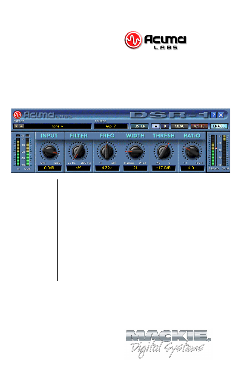
The DSR-1 plug-in for the Mackie D8B is a highly accurate,
frequency controlled, three-band dynamics processor. It enables
you to quickly isolate and correct unwanted sibilance in vocal
recordings of singers and speakers. The DSR-1 reduces
annoying sibilant and popping sounds that are often found in
recordings without losing the crisp top-end clarity. Don’t let the
simple chicken-head controls and the funky retro-look fool you.
The DSR-1 is a highly professional tool that is ideal for editing
vocals, instrumentals, and other sources. The DSR-1 is an
invaluable plug-in for your D8B that can save a great recording
by removing troublesome frequencies.
About Acuma Labs
Acuma Labs develops real-time embedded systems for
professional audio applications to create high-quality products
for the music and pro-audio industries. Acuma specializes in
digital audio effects using DSP, real-time operating systems,
graphical user interfaces, and digital hardware design.
4
Acuma DSR-1 De-Esser
Page 5

About the D8B UFX Card
The Mackie UFX card provides robust processing power for
computation-heavy plug-ins. The UFX card is a 4-in/4-out
architecture, which means that it supports four mono plug-ins or
two mono and one stereo, or two stereo plug-ins simultaneously.
Up to four UFX cards can be installed in the D8B, allowing up to
sixteen simultaneous single-channel effects, eight stereo plugins, or combinations there of.
Note: Earlier D8Bs were fitted with 16 MB of memory. It is recommended that
you increase this to 32 MB (as fitted in newer D8Bs) if you install more than one
UFX card. Memory upgrade instructions are supplied with each UFX card.
About the DSR-1 (De-esser)
The DSR-1 employs mid- or high-frequency compression. The
frequency and bandwidth controls are used to isolate the
problematic frequency range. No external keying device is
required. The ess band Key Listen feature allows you to solo (or
listen) to the isolated frequency range. The DSR-1 can also help
to compress shrill, high-pitched sounds that may accompany
acoustic instruments. The DSR-1 includes a high-pass filter that
helps you to clean up other artifacts such as microphone pops.
The DSR-1 includes a series of great male and female vocal,
instrument, and spoken word presets that can make the
toughest job easy to correct. As with all D8B plug-ins, all of
DSR-1’s parameters are automatable, and can be saved as user
presets.
User’s Guide
5
Page 6

Let’s Get Started
Requirements
• One or more Mackie UFX cards
• Mackie Real Time OS 3.0 Software
• Plug-in Software
We will assume you have successfully installed a Mackie UFX
card and Mackie Real Time OS 3.0 software upgrade. If you have
encountered problems with the installation of hardware or
software, please see their associated user guides or contact
Mackie support (www.mackie.com).
Please see the Licensing section of the Digital 8•Bus version 3.0
owner’s manual for information on both authorizing the plug-in,
and the unlock procedure.
Please see Appendix C of the Digital 8•Bus version 3.0 owner’s
manual for information on configuring the plug-in.
Main Features
• Frequency dependant de-essing reduces problematic esses
without loss of clarity
• High-pass FILTER helps to clean up unwanted artifacts such as
microphone pops
• FREQ/WIDTH sets the frequency range for exact de-esser
processing
• Built in DC filter eliminates DC offset from the input signal
• LISTEN enables you to hear the isolated ess frequency band
•Vintage look has a funky, easy-to-use interface
•WRITE button automates your edits into the D8B session
•Memory A/B are two convenient storage banks for A/B
comparison
• ENABLE/Disable bypasses processing
•MENU has Load Preset, Save, Save As, Cut, Copy, Paste, etc.
• Factory/User Presets are Male, Female Vocal, Instrumental, etc.
• THRESHOLD adjusts the band energy level at which ess band
compression starts occurring
•RATIO adjusts the amount of compression applied to the band
• Individual input, output, S-band, and gain reduction meters.
6
Acuma DSR-1 De-Esser
Page 7

Using the DSR-1
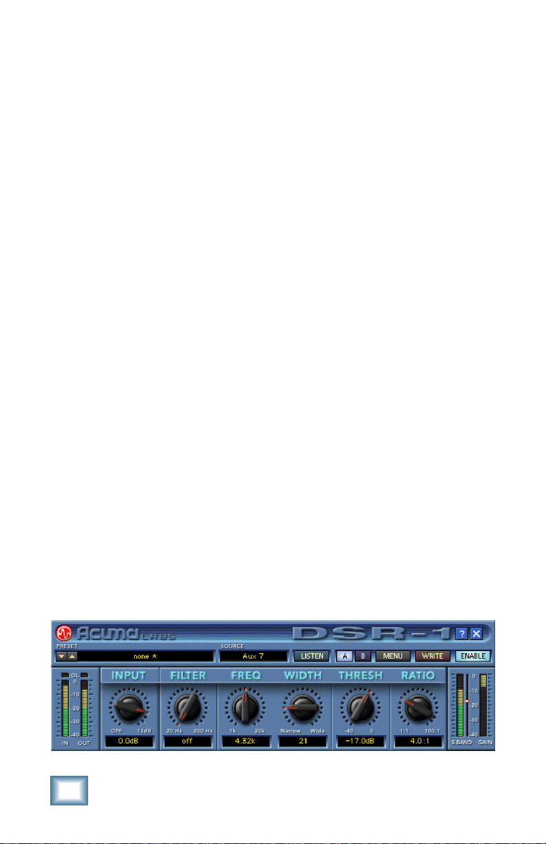
Front Panel Overview
You can think of the DSR-1 as being broken into five basic areas:
the status block, global block, I/O block, controls, and meters.
DSR-1 Block break down overview
Status Block (See page 8)
The status block includes the PRESET up/down toggle buttons,
Preset Title window, and SOURCE (input select).
Global Controls Block (See page 9)
The global controls include: ess band (key) LISTEN, Mem A and
B select buttons, MENU, WRITE, ENABLE, HELP, and minimize
buttons.
I/O Levels Block (See page 11)
The I/O block is comprised of the input (IN) and output (OUT)
meters and the INPUT level adjustment ranging from off to
+12 dB.
Controls Block (See page 12)
The controls block is the heart of DSR-1. It includes the high-pass
FILTER, as well as FREQuency and bandWIDTH control for
selecting the ess band (ess range 1k to 20k). The controls block
also includes the THRESHold control (–49 dB to 0 dB), and the
RATIO control (1:1 to 100:1).
User’s Guide
7
Page 8

Meters (See page 14)
There are separate meters to indicate the ess-band level and the
ess-band gain reduction amount.
The Status Block
DSR-1 Status Block
Preset Toggle Buttons
The PRESET up/down arrows, located just to the left of the
preset window, enable you to scroll up or down through either
the factory or user presets.
Tip: In most vocal recordings, there are usually a number
of areas that could be improved with the DSR-1. However,
there is not necessarily one overall optimum setting that
will work throughout the track. Building user presets is a
good way to have multiple De-esser settings that can be
quickly accessed. You can then apply these settings to
various regions of your track. There is no delay time in
loading presets. You might try building performances by
stacking user presets and toggling between them using
the up/down arrows. These are located at the left side of
the preset window. You could also insert a load preset
event in the mix editor.
For example, you can quickly switch from a Verse Ess to
Chorus Ess preset and back. This would eliminate
problematic spots in your recording. Additionally,
pressing the WRITE button automates your changes as
part of the D8B session.
Note: See the section on the WRITE button for more information on how this
works. The user preset list sorts alphabetically. If you want your user presets
to come up in a certain order, use letters at the beginning of the preset names.
(I.e. Aesss, Besss, Cesss, etc.).
8
Acuma DSR-1 De-Esser
Page 9

PRESET Title Window
The PRESET Title window is located at the top of the control
bar. It displays the currently selected preset corresponding to
the existing DSR-1 settings. Click on the window to access the
pull-down menu where you choose between factory or user
presets.
Note: It is possible to save presets to the User Preset folder, which is the
default folder, or a folder of your own making. The user presets point to
the last folder you’ve saved or recalled presets from.
SOURCE
The input select is located directly to the right of the PRESET
Title window. Use your mouse to select from pre/post insert,
auxiliary, or master insert inputs. In general, the DSR-1 is
intended to be used as a channel insert.
Global Controls Block
DSR-1 Global Controls Block
LISTEN
The LISTEN button acts like a solo that lets you hear (solo) the
frequency band set with the FREQ and WIDTH pots in the
Controls block. Selecting LISTEN isolates (or solos) this range.
This should help you zero in on annoying sibilance by using your
ears to identify where the problem is occurring.
Memory A/Memory B
The Mem A and Mem B buttons temporarily store DSR-1
settings to allow comparative referencing. You can also copy and
paste settings from one memory location to another.
User’s Guide
9
Page 10

MENU
Pressing the MENU button opens a pull-down menu. This menu
performs familiar functions such as load, save as, cut, copy, and
paste. It also displays the plug-in’s build number and version.
WRITE
WRITE enables the D8B’s automation so all the changes you
make in the DSR-1 plug-in are recorded as part of the D8B
session. This works similarly to a channel’s write button. To
record automation for a plug-in, ALL must be turned on in the
automation section of the D8B. Automation must also be out of
Bypass. Plug-in parameter edits are recorded when the D8B is
recording, but only if the plug-in’s WRITE button is on, or if
Auto Touch is turned on. Auto Touch is located in the
automation section. When you press stop, the plug-in’s WRITE
button turns off.
ENABLE
The ENABLE button either enables or bypasses the DSR-1.
Help Screen (?)
Pressing the help screen (?) button brings up a quick-start
screen to quickly get you using the plug-in. It’s also useful for
quick reference.
The Help Screen
Minimize Button (X)
The minimize button (X) in the top-right corner hides the screen.
However, the screen is still active until it is disabled in the D8B
Plug-ins window.
10
Acuma DSR-1 De-Esser
Page 11

I/O Levels
DSR-1 I/O Levels
IN/OUT
The input and output meters are located at the far-left side.
These meters represent the incoming signal and the output (post
effect) signal.
OL
OL (overload) is represented by the two small boxes above the
in/out meters. The left-most overload indicator is for input level,
and the other one is for output. They flash red if overload is
occurring.
INPUT
The INPUT knob determines the gain or attenuation that is
applied to the input signal.
User’s Guide
11
Page 12

Controls Block
DSR-1 Controls Block
Note: Only the signal in the band selected by the FREQ and WIDTH controls are affected by the DSR-1. Signal outside of this range, both above and
below in frequency, is unaffected.
FILTER
The FILTER knob controls a high-pass filter ranging from 20Hz
to 200Hz. It offers you a quick and convenient way to reduce
low-frequency noise. The high-pass filter can be very useful in
eliminating unwanted artifacts such as microphone pops.
FREQ and WIDTH
The FREQ and WIDTH pots are used to select the ess range.
FREQ, ranging from 1kHz to 20kHz, is the center point of the
range. WIDTH ranges from 1 to 100, with 1 being a very narrow
band and 100 being very wide. Use your ears to locate a
troublesome frequency range by enabling the LISTEN feature
to hear a set ess range. Then use the FREQ and WIDTH pots to
adjust the range. (See LISTEN in the Global Block description).
12
A Closer Look: Start by routing a vocal track into the
DSR-1. Typically use a pre- or post-insert, and set the
DSR-1’s input to an acceptable level. Notice the
relationship between your FREQ and WIDTH settings
and the ess meter level. The ess meter level is located
in the output meters block on the right side. Start by
pressing the LISTEN button to facilitate isolation of the
ess band. To start with, set the ratio to 1:1 so that no
compression is applied to the band. Now adjust the
Acuma DSR-1 De-Esser
Page 13

FREQ and WIDTH pots so you hear as much of the
problematic sibilance as possible. At the same time,
minimize the amount coming through of the signal you
wish to leave unaffected. Typically, you will find a
center frequency in the range of 3k to 6k, with a width
ranging from 20 to 40 is useful. Watch the key level
change as you adjust to the frequencies of the ess
range. Now adjust the DSR-1’s threshold level using
the threshold pot. The threshold level is also portrayed
as the small horizontal bar between the S-BAND and
GAIN meters. Watching this is a good way to meter
where your threshold level should be after you have
dialed in an ess range. The DSR-1 only affects a signal
that is above the set threshold. Finally, adjust your
RATIO pot to apply a desired amount of compression to
your specified ess range. For example, 3:1 means that
if a signal is 3 dB over the threshold, it will be reduced
in amplitude to 1 dB over the set threshold. Now you’ve
got a good starting point. Take it out of LISTEN mode
and continue to tweak the parameters until you’ve got
the sound you want!
DSR-1 threshold indicator and S-BAND/GAIN meters
Note: You may need to change threshold levels to compensate for adjustments made with the FREQ and WIDTH pots.
THRESH
THRESH (threshold range) ranges from –40 to 0 dB, and is
adjusted using the THRESH knob. S-band signal above this
threshold will get reduced in amplitude by an amount
determined by the ratio. See “A Closer Look,” above for further
information.
User’s Guide
13
Page 14

RATIO
The RATIO select is set to usual compressor increments that
range from 1:1 to 100:1. Simply turn the pot to set a desired
ratio. For example, 3:1 means that if a signal is 3 dB over the
threshold, it will be reduced in amplitude to 1 dB over the set
threshold. See “A Closer Look” on page 12 for further
information.
Note: The GAIN meter displays gain reduction. The LED moves downward
from the top of the meter starting at 0 dB and indicates negative dB, or
gain reduction.
Meters (S-BAND and GAIN)
The two meters in the lower right corner of the screen represent
the S-BAND meter and the GAIN (reduction) meter.
GAIN (Gain Reduction)
The gain reduction meter ranges from 0 dB to –40 dB and the
LED’s come down from the top of the meter, (0 dB), in an
opposite fashion as compared to regular level meters.
S-BAND
The S-BAND meter represents the dB level of the ess band. The
small white bar located between the S-BAND and GAIN meters
is a visual representation of the threshold that can be adjusted
using the threshold pot.
Please see Appendix C of the Digital 8•Bus version 3.0 owner’s
manual for information on:
• Saving, loading and resetting a preset
• Automation and snapshot control
• Dynamic real time and dynamic off-line
• FX routing
14
Acuma DSR-1 De-Esser
Page 15

DSR-1 Plugin Configuration
Specifications
In/Out
Level meters -40 to 0 dB
Input Control
Off to +12.0 dB
High-Pass Filter
Off to 20Hz-200Hz (4th Order)
Frequency
1kHz to 20kHz specifies
the middle
point of
the ess
band
Width
Narrow to Wide specifies
the width
of the ess
band
Threshold
–40 dB to 0 dB
DSR-1 Plugin Load
Ratio
1:1 to 100:1
S-band (Key) Meter
–40 dB to 0 dB
Gain Reduction Meter
–40 dB to 0 dB
User’s Guide
15
Page 16

DSR-1 Factory Presets
The following table is a simple guideline to help you understand
the factory presets, and what settings were applied to the
individual presets. Don't be afraid to run anything through the
plug-in preset, though. Then customize the parameters to your
specific needs, and save it as a user preset. So get creative and
have fun! Please visit www.acumalabs.com periodically to
download more audio examples and free presets.
Preset Name Frequency Width Ratio Description
2K Medium 2K 30 5.8:1 Frequency is set at 2K with a medium width
2K Narrow 2K 16 5.8:1 Frequency is set at 2K with a narrow width
2K Wide 2K 50 5.8:1 Frequency is set at 2K with a wide width
3K Medium 3K 30 5.8:1 Frequency is set at 3K with a medium width
3K Narrow 3K 16 5.8:1 Frequency is set at 3K with a narrow width
3K Wide 3K 50 5.8:1 Frequency is set at 3K with a wide width
4K Medium 4K 30 5.8:1 Frequency is set at 4K with a medium width
4K Narrow 4K 16 5.8:1 Frequency is set at 4K with a narrow width
4K Wide 4K 50 5.8:1 Frequency is set at 4K with a wide width
5K Medium 5K 30 5.8:1 Frequency is set at 5K with a medium width
5K Narrow 5K 16 5.8:1 Frequency is set at 5K with a narrow width
5K Wide 5K 50 5.8:1 Frequency is set at 5K with a wide width
6K Medium 6K 30 5.8:1 Frequency is set at 6K with a medium width
6K Narrow 6K 16 5.8:1 Frequency is set at 6K with a narrow width
6K Wide 6K 50 5.8:1 Frequency is set at 6K with a wide width
Female 6K 22 5.8:1 Optimized for female singing or
speaking frequencies
Male 3.35K 34 3.8:1 Optimized for male singing or
speaking frequencies
16
Acuma DSR-1 De-Esser
Page 17

Preset Name Frequency Width Ratio Description
Squeeky Acoustic 3.8K 74 13:1 Helps to reduce annoying string squeaks
from acoustic guitars
Fret Noise 3K 42 NA Used to diminish miscellaneous fret noise
Sting Buzz 1 3K 87 27:1 ***Helps to hide buzzing fret and string noise
Sting Buzz 2 4.8K 56 100:1 ***Helps to hide buzzing fret and string noise
when close miking strings
Try quickly punching DSR-1 in and out to eliminate noise without
losing top end.
User’s Guide
17
Page 18

18
Acuma DSR-1 De-Esser
Page 19

User’s Guide
19
Page 20

®
™
©2001 Mackie Designs Inc. and Acuma Labs. All Rights Reserved.
Part No. 0000651 Rev. A 12/2001
 Loading...