

Page 1

DRM212 • DRM215 • DRM315
Professional Powered Loudspeaker Series
OWNER’S MANUAL
Page 2
Important Safety Instructions
1. Read these instructions.
2. Keep these instructions.
3. Heed all warnings.
4. Follow all instructions.
5. Do not use this apparatus near water.
6. Clean only with a dry cloth.
7. Do not block any ventilation openings. Install in accordance
with the manufacturer’s instructions.
8. Minimum distance (5 cm) around the apparatus for sucient ventilation.
The ventilation should not be impeded by covering the ventilation openings
with items, such as newspapers, table-cloths, curtains, etc.
9. Do not install near any heat sources such as radiators, heat registers,
stoves, or other apparatus (including amplifiers) that produce heat.
10. No naked flame sources, such as lighted candles, should be placed
on the apparatus.
11. Do not defeat the safety purpose of the polarized or grounding-type plug.
A polarized plug has two blades with one wider than the other. A grounding-type
plug has two blades and a third grounding prong. The wide blade or the third
prong are provided for your safety. If the provided plug does not fit into your
outlet, consult an electrician for replacement of the obsolete outlet.
12. Protect the power cord from being walked on or pinched particularly at plugs,
convenience receptacles, and the point where they exit from the apparatus.
13. Only use attachments/accessories specified by the manufacturer.
14. Use only with a cart, stand, tripod, bracket, or table
specified by the manufacturer, or sold with the apparatus.
When a cart is used, use caution when moving the cart/
apparatus combination to avoid injury from tip-over.
15. Unplug this apparatus during lightning storms or when
unused for long periods of time.
16. Refer all servicing to qualified service personnel. Servicing
is required when the apparatus has been damaged in any
way, such as power-supply cord or plug is damaged, liquid has been spilled or
objects have fallen into the apparatus, the apparatus has been exposed to rain
or moisture, does not operate normally, or has been dropped.
DRM Professional Powered Loudspeaker Series
17. This apparatus shall not be exposed to dripping or splashing, and no object filled
with liquids, such as vases or beer glasses, shall be placed on the apparatus.
18. Do not overload wall outlets and extension cords as this can result in a risk
of fire or electric shock.
CAUTION
RISK OF ELECTRIC SHOCK! DO NOT OPEN!
CAUTION: TO REDUCE THE RISK OF ELECTRIC SHOCK DO NOT
REMOVE COVER (OR BACK). NO USER-SERVICEABLE PARTS INSIDE.
REFER SERVICING TO QUALIFIED PERSONNEL.
The lightning flash with arrowhead symbol within an equilateral
triangle is intended to alert the user to the prescence of uninsulated
“dangerous voltage” within the product’s enclosure, that may be of
significant magnitude to constitute a risk of electric shock to persons.
The exclamation point within an equilateral triangle is intended
to alert the user of the prescence of important operating and
maintaining (servicing) instructions in the literature accompanying
the appliance.
WARNING — To reduce the risk of fire or electric shock, do not
expose this apparatus to rain or moisture.
PORTABLE CART
WARNING
19. This apparatus has been designed with Class-I construction and
must be connected to a mains socket outlet with a protective earthing
connection (the third grounding prong).
20. This apparatus has been equipped with a rocker-style AC mains power
switch. This switch is located on the rear panel and should remain readily
accessible to the user.
21. The MAINS plug or an appliance coupler is used as the disconnect device,
so the disconnect device shall remain readily operable.
22. The use of apparatus is in tropical and/or moderate climates.
23. NOTE: This equipment has been tested and found to comply with the limits
for a Class A digital device, pursuant to part 5 of the FCC Rules. These
limits are designed to provide reasonable protection against harmful
interference when the equipment is operated in a commercial environment.
This equipment generates, uses, and can radiate radio frequency energy
and, if not installed and used in accordance with the instruction manual,
may cause harmful interference to radio communications. Operation
of this equipment in a residential area is likely to cause harmful interference
in which case the user will be required to correct the interference at his
own expense.
CAUTION: Changes or modifications to this device not expressly approved
by LOUD Audio, LLC could void the user’s authority to operate the equipment
under FCC rules.
24. This apparatus does not exceed the Class A/Class B (whichever
is applicable) limits for radio noise emissions from digital apparatus
as set out in the radio interference regulations of the Canadian Department
of Communications.
ATTENTION
— Le présent appareil numérique n’émet pas de bruits
radioélectriques dépassant las limites applicables aux appareils
numériques de class A/de class B (selon le cas) prescrites dans
le réglement sur le brouillage radioélectrique édicté par les ministere
des communications du Canada.
25. Exposure to extremely high noise levels may cause permanent hearing loss.
Individuals vary considerably in susceptibility to noise-induced hearing loss,
but nearly everyone will lose some hearing if exposed to suciently intense
noise for a period of time. The U.S. Government’s Occupational Safety and
Health Administration (OSHA) has specified the permissible noise level
exposures shown in the following chart.
According to OSHA, any exposure in excess of these permissible limits
could result in some hearing loss. To ensure against potentially dangerous
exposure to high sound pressure levels, it is recommended that all persons
exposed to equipment capable of producing high sound pressure levels
use hearing protectors while the equipment is in operation. Ear plugs or
protectors in the ear canals or over the ears must be worn when operating
the equipment in order to prevent permanent hearing loss if exposure is in
excess of the limits set forth here:
Duration, per
day in hours
8 90 Duo in small club
6 92
4 95 Subway Train
3 97
2 00 Very loud classical music
.5 02
05 Matt screaming at Troy about deadlines
0.5 0
0.25 or less 5 Loudest parts at a rock concert
Sound Level dBA,
Slow Response
Typical Example
CAUTION — To prevent electric shock hazard, do not connect
to mains power supply while grille is removed.
Laite on liitettävä suojakoskettimilla varustettuun pistorasiaan.
Apparatet må tilkoples jordet stikkontakt.
Apparaten skall anslutas till jordat uttag.
Correct disposal of this product: This symbol indicates that this product should not be disposed of with your household waste, according to the WEEE directive (202/9/EU)
and your national law. This product should be handed over to an authorized collection site for recycling waste electrical and electronic equipment (EEE). Improper handling of this type of waste
could have a possible negative impact on the environment and human health due to potentially hazardous substances that are generally associated with EEE. At the same time, your cooperation
in the correct disposal of this product will contribute to the eective usage of natural resources. For more information about where you can drop o your waste equipment for recycling, please
contact your local city oce, waste authority, or your household waste disposal service.
2
DRM Professional Powered Loudspeaker Series
Page 3

Contents Features
Owner’s Manual
Important Safety Instructions ........................................... 2
Contents / Features ............................................................ 3
Introduction / Getting Started ........................................... 4
Hookup Diagrams ............................................................... 5
DRM Loudspeakers: Rear Panel Features .......................0
1. Power Connection ...................................................0
2. Power Switch ..........................................................0
3. XLR and 1/4” Combo Inputs ...................................0
4. Gain [Ch. 1 and 2] ...................................................
5. Direct Out [Ch. 1 and 2] .........................................
6. 1/8” Input [Ch. 3/4] ................................................
7. Gain [Ch. 3/4] .........................................................
8. Mix Out ....................................................................
9. LCD Display ............................................................
10. Speaker Control Knob ..........................................
DRM Control Dashboard™ ................................................2
Main .............................................................................2
Speaker Mode .............................................................2
Sub ..............................................................................3
EQ Setup ......................................................................4
Delay ............................................................................5
Configuration ..............................................................6
Protection Circuitry ...........................................................8
Limiting .......................................................................8
Overexcursion Protection ..........................................8
Thermal Protection ....................................................8
AC Power ............................................................................9
Care and Maintenance ......................................................9
Placement ..........................................................................9
Room Acoustics ................................................................ 20
Rigging ..............................................................................2
Appendix A: Service Information ..................................... 22
Appendix B: Technical Information ................................. 23
DRM Dimensions ....................................................... 25
DRM Block Diagram .................................................. 26
Limited Warranty .............................................................. 27
• High-eciency Class-D amplifiers
o Up to 2300W of power oers ample headroom
for professional applications
o Universal power supply (00-240 VAC) with Power
Factor Correction technology ensures consistent
performance even with unstable AC power
o Next-gen protection circuitry keeps transducers safe
and ensures peak performance in all applications
• Advanced Impulse™ DSP module
o Precision crossovers and transducer time-alignment
deliver reference quality sound that is consistent
throughout the frequency range
o Cutting-edge FIR Filtering drastically reduces inherent
anomalies, phase issues, and muddy midrange resulting
in crystal clear sound
• DRM Control Dashboard™ features a high-contrast full
color display for easy single-knob access to configuration,
processing, and more
o View current EQ and voicing mode, high-resolution
metering, and more from a single overview window
o Application and venue specific modes provide easy
to use voicing with minimal setup time
o Adjustable 3-band parametric EQ allows for additional
customization and tuning for your application and venue
o Alignment Delay control for delay stacks
o Save and recall up to 6 user presets for various
applications and venues
o Screensaver plus dimmer and contrast control
o System lock with 4-digit passcode
• Dual independent inputs that support mic, line, and instrument
signals plus a dedicated /8" stereo aux input
• Premium components and cabinet design
o Road-worthy plywood construction and internal bracing
oers optimal acoustic performance with a touring-grade
textured coating and powder-coated heavy gauge steel
grille
o Unique ported design provides exceptionally smooth yet
punchy low frequency response while providing cool air
directly to the internal amplifier
o Titanium diaphragm compression drivers are perfectly
matched to the amplifier for maximum transparency
and clarity
o Custom high-excursion woofers oer minimal distortion
with increased bass response and reliability to withstand
the most demanding live applications
• Versatile configuration
o DRM22 and DRM25 feature an angled cabinet design
for use as floor monitors and dual angle pole-mounts
for optimal coverage
o DRM35 features a single angle pole-mount
• Professional rigging options
o M0 flypoints for professional installations**
Like us
Part No. SW266 Rev. A 0/9
©2019 LOUD Audio, LLC. All Rights Reserved.
Follow us
**DRM22 and DRM25 can be flown in vertical orientation only
**DRM35 can be flown in both horizontal and vertical orientation
Watch our dang videos
Owner’s Manual
3
Page 4
Introduction
Getting Started
DRM Series Professional Powered Loudspeakers deliver
class-leading power via ultra-ecient Class-D amplifiers
with next-gen protection and Power Factor Correction
technology for peak performance when you need it.
Advanced Impulse™ DSP provides acoustic correction
and time-alignment via precision tuned FIR filters for crystal
clear, punchy sound typically experienced only with massive
touring systems. The DRM Control Dashboard™ features
a high-contrast, full-color display on the back panel for quick
and easy setup.
Custom transducers housed in touring-grade plywood
cabinets are designed for consistent performance
in the most demanding applications.
Equipped with M0 flypoints, dual angle pole mounts,
and available line array configurations – the DRM Series is
perfect for clubs, houses of worship, rental systems
and more.
How to Use This Manual:
Afer this introduction, a getting started guide will help
you get things set up fast. The hookup diagrams show some
typical DRM loudspeaker setups, including some that involve
DRM Professional Powered Loudspeaker Series
the DRM8S subwoofer.
This icon marks information that is critically
important or unique! For your own good, read and
remember them...it is a good idea to pay special
attention to these areas in the Owner’s Manual
marked with the “VERY IMPORTANT” hand icon.
The following steps will help you set up the loudspeakers
quickly.
. Make all initial connections with the power switches OFF
on all equipment. Make sure the master volume, level and gain
controls are all the way down.
2. If not using a subwoofer, connect the outputs from
the mixing console (or other signal source) to the inputs
on the rear panel of the loudspeakers.
3. If using a subwoofer, connect the outputs from
the mixing console (or other signal source) to the inputs
on the subwoofer, then connect the high pass outputs
from the subwoofer to the inputs of the loudspeakers.
4. Push the line cord securely into the subwoofer’s /
loudspeaker’s IEC connectors and plug the other ends into
grounded AC outlets. The subwoofer/loudspeaker may accept
the appropriate voltage as indicated near the IEC connector.
5. Turn the mixer (or other signal source) on.
6. Turn the subwoofer on (if applicable).
7. Turn the loudspeakers on.
8. Make sure the loudspeaker’s channel levels are set
to (or near) 0 dB.
9. Start the signal source and raise the mixer’s main L/R
fader up to a comfortably loud listening level.
There’s an illustration of a microscope,
so, of course, you’re going to get more
detailed information when you see this little
guy. There are explanations of features
and practical tips listed here.
It’s a good idea to pay attention to text displayed
next to a note icon, as this icon draws attention
to certain features and functions relating to the
usage of the DRM Series.
Please write the serial numbers here for future reference
(i.e., insurance claims, tech support, return authorization,
make dad proud, etc.)
Purchased at:
Date of purchase:
Things to Remember:
• Never listen to loud music for prolonged periods. Please see
the Safety Instructions on page 2 for information on hearing
protection.
• As a general guide, the mixer (or other signal source) should
be turned on first, subwoofers next, and DRM loudspeakers
last. As such, the DRM loudspeakers should also be turned
o first, followed by the subwoofers, then the mixer. This will
reduce the possibility of any turn-on or turn-o thumps
and other noises generated by any upstream equipment
from coming out of the speakers.
• Save the shipping boxes and packing materials! You may
need them someday. Besides, the cats will love playing
in them and jumping out at you unexpectedly. Remember
to pretend like you are surprised!
• Save your sales receipt in a safe place.
4
DRM Professional Powered Loudspeaker Series
Page 5
Hookup Diagrams
SPEAKER CONTROL
PUSH FOR SETTINGS
GAIN GAIN
GAIN
U
U
MIC
MIC
LINE
LINE
+50dBOFF
+50dBOFF
MAXOFF
INPUT INPUT
INPUT
MIX OUTDIRECT OUTDIRECT OUT
SPEAKER VOICING
LIVE SHOW
LIVE
SPEECH
Owner’s Manual
SPEAKER CONTROL
CLUB
MON
PUSH FOR SETTINGS
SPEAKER CONTROL
GAIN GAIN
U
LINE
GAIN
U
MIC
LINE
+50dBOFF
+50dBOFF
INPUT
INPUT INPUT
PUSH FOR SETTINGS
MIC
SPEAKER VOICING
MONITOR POSITION
LIVE
SPEECH
MAXOFF
MIX OUTDIRECT OUTDIRECT OUT
CONFIGURATION
MEMORY 1 2 3 4 5 6
LOCK PIN 1 2 3 4
CH2 IN LO-Z HI-Z
BACKLIGHT
FRONT LED
RESET
ABOUT
OFF DIM ON
OFF ON
CLUB
MON
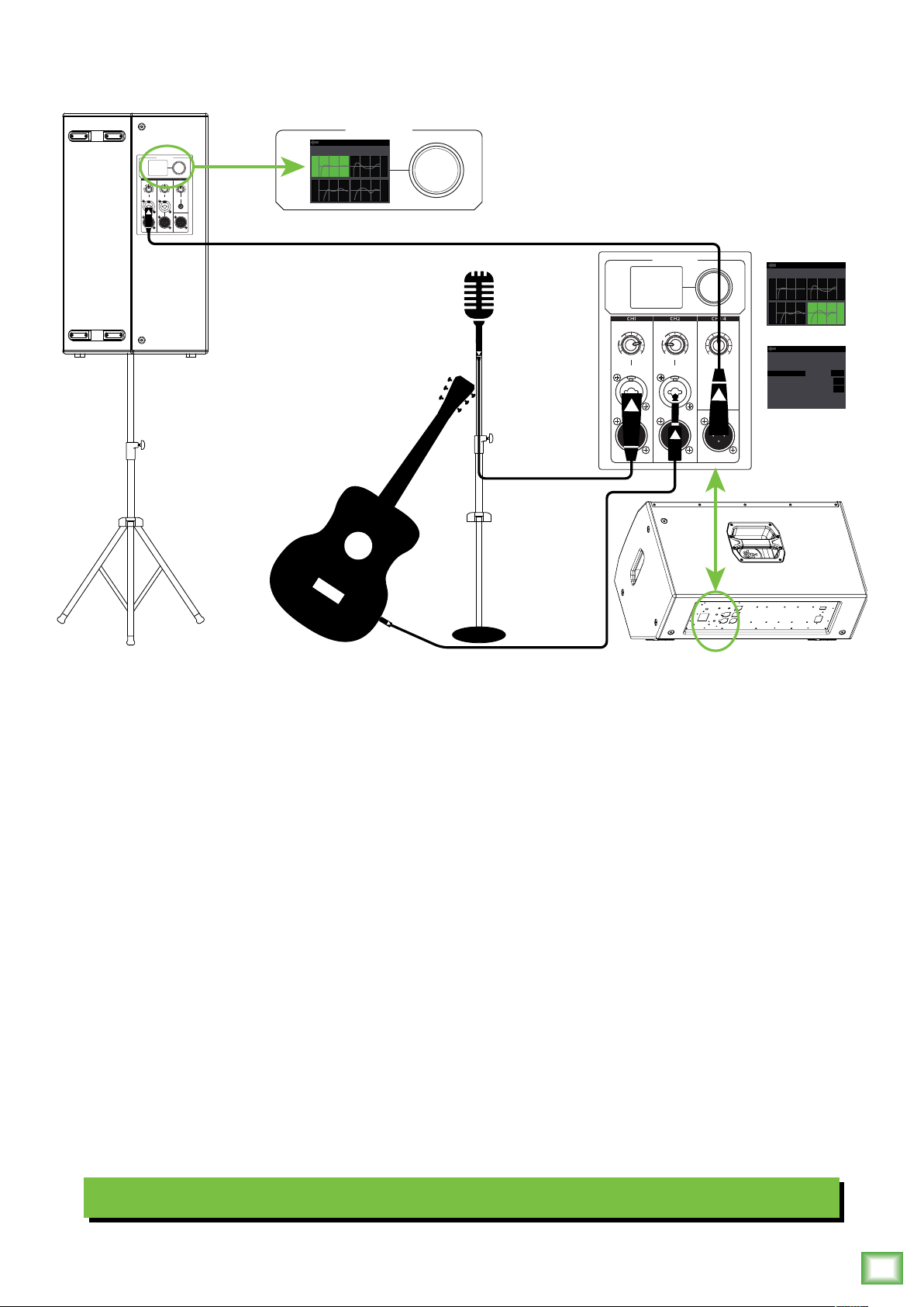
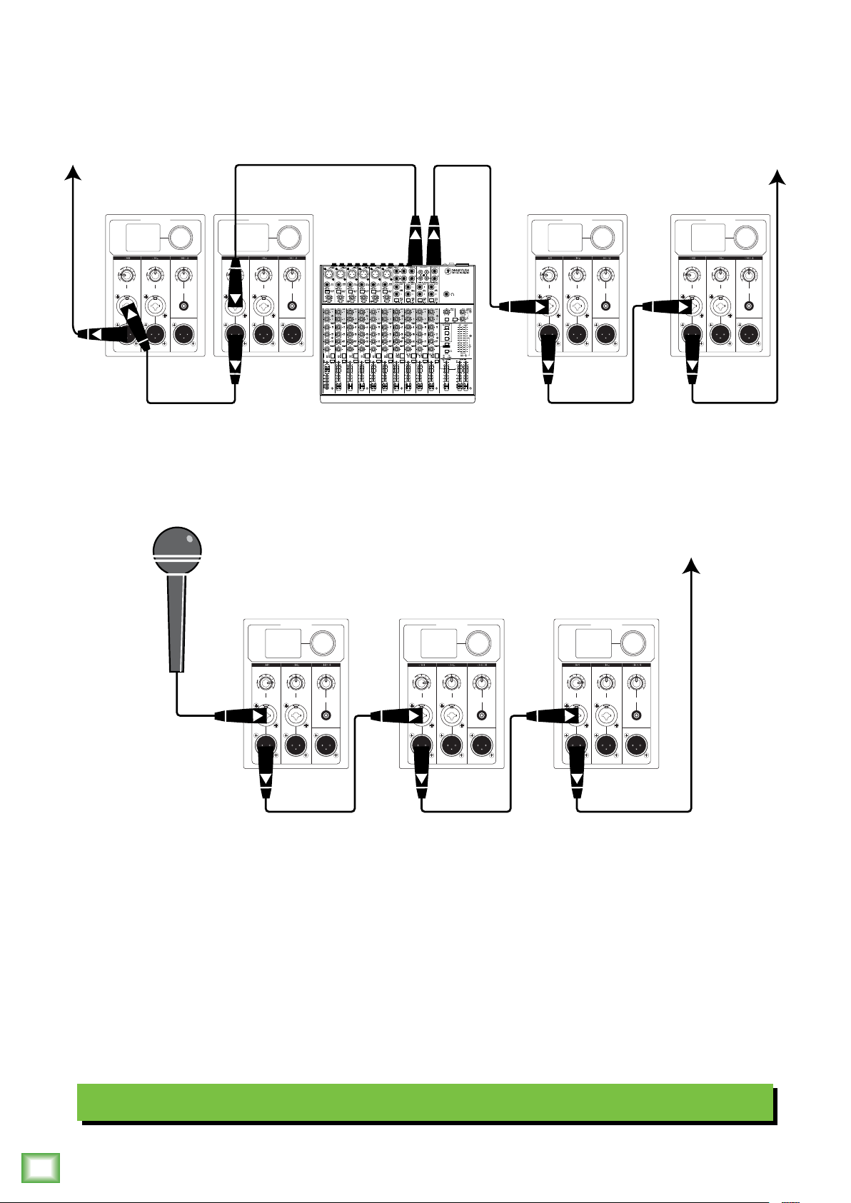
DRM loudspeakers are the perfect tool for singer-songwriters touring the local coee shops. Bring your favorite axe
and mic, DRM loudspeakers and cables and power cords.
In this example, a dynamic microphone is connected to the channel input of a DRM22 loudspeaker, used for monitoring
purposes.
Now grab your axe and plug it directly into the channel 2 input. Or if you use eects, connect the guitar to the eects input
and another cable from the eects output to the channel 2 input.
A DRM25 loudspeaker will be used for the main PA. Simply connect a cable from the DRM22 monitor’s MIX OUT jack
to the DRM25 PA’s channel input.
For the output, you will want to set a speaker mode, described in detail on page 2. For this type of setup, Live works well
for the main DRM25. Select the Monitor mode for the DRM22 monitor. Additionally, you will want to set the monitor’s
configuration > channel 2 input to Hi-Z to account for the guitar.
Singer-Songwriter Setup
Owner’s Manual
5
Page 6
Hookup Diagrams continued...
SPEAKER CONTROL
PUSH FOR SETTINGS
GAIN GAIN
GAIN
U
U
MIC
MIC
LINE
LINE
+50dBOFF
+50dBOFF
MAXOFF
INPUT INPUT
INPUT
MIX OUTDIRECT OUTDIRECT OUT
SPEAKER VOICING
LIVE SHOW
LIVE
SPEECH
SPEAKER CONTROL
LINE
HI-Z
CLUB
MON
PUSH FOR SETTINGS
GAIN GAIN
U
MIC
LINE
+50dBOFF
INPUT INPUT
SPEAKER CONTROL
PUSH FOR SETTINGS
GAIN
U
MIC
LINE
+50dBOFF
MAXOFF
INPUT
MIX OUTDIRECT OUTDIRECT OUT
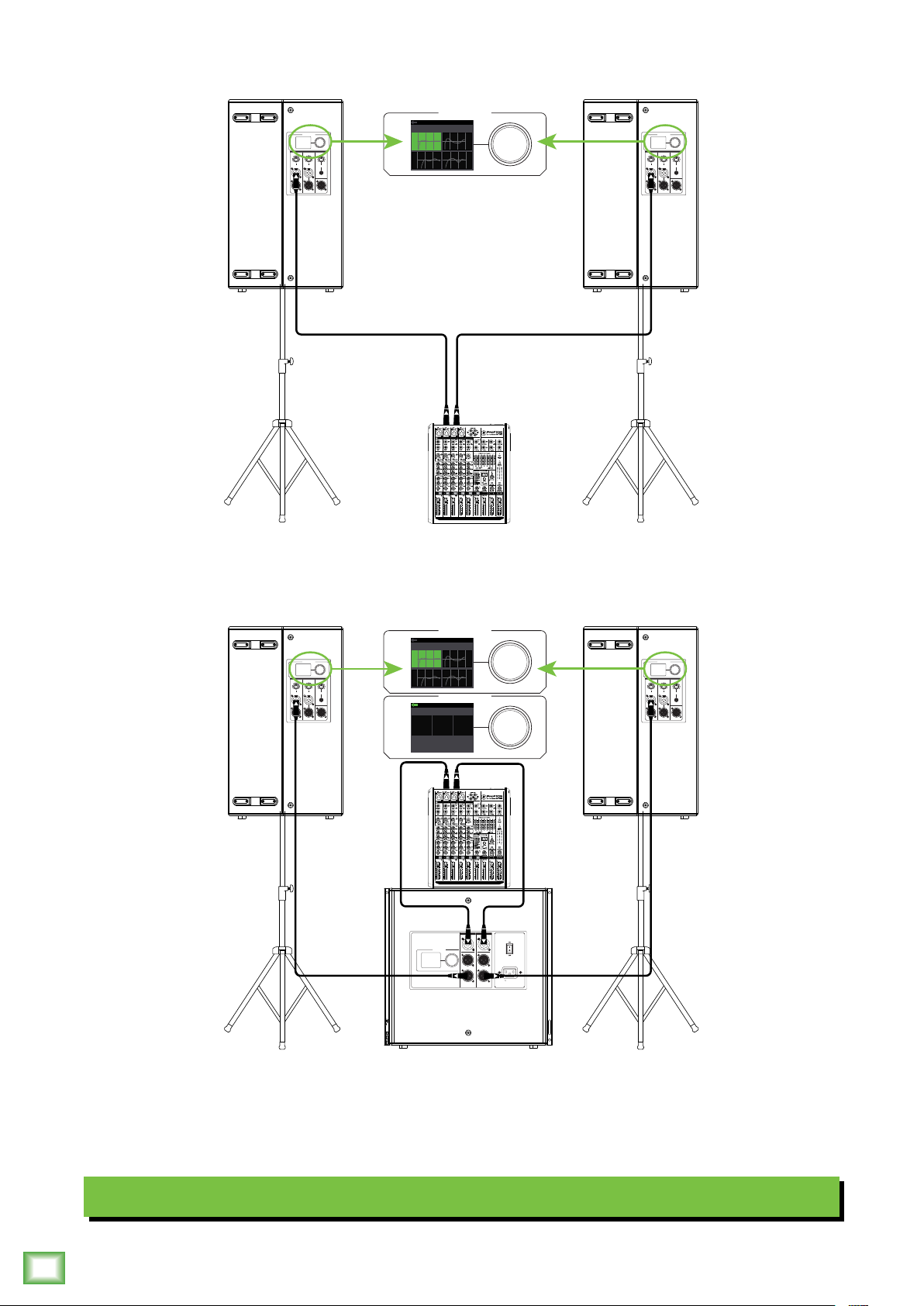
In this example, a ProFX8v2 mixer is connected directly to two DRM25 loudspeakers. It is the perfect setup for a small
club or... a fun karaoke house party! Simply connect the L/R outputs of the ProFX8v2 mixer to the CH input of each
DRM25 loudspeaker. Don’t forget to set the Speaker Mode on both loudspeakers to Live... or Club if you want a little
more low-end thump!
DRM Professional Powered Loudspeaker Series
GAIN GAIN
U
MIC
LINE
+50dBOFF
INPUT INPUT
SPEAKER CONTROL
PUSH FOR SETTINGS
GAIN
U
MIC
LINE
+50dBOFF
MAXOFF
INPUT
MIX OUTDIRECT OUTDIRECT OUT
SPEAKER VOICING
LIVE SHOW
LIVE
SPEECH
SUBWOOFER HPF
DRM SUB
SPEAKER CONTROL
SPEAKER CONTROL
DRM
SUB
LINE
HI-Z
SPEAKER CONTROL
PUSH FOR SETTINGS
VAROFF
CLUB
MON
INPUT
DIRECT OUT
HIGH-PASS OUT HIGH-PASS OUT
PUSH FOR SETTINGS
PUSH FOR SETTINGS
INPUT
DIRECT OUT
SPEAKER CONTROL
PUSH FOR SETTINGS
GAIN GAIN
GAIN
U
U
MIC
MIC
LINE
LINE
+50dBOFF
+50dBOFF
MAXOFF
INPUT INPUT
INPUT
MIX OUTDIRECT OUTDIRECT OUT
100-240VAC
50-60 Hz 110W
If you desire a little more boom, add a DRM8S subwoofer to the mix. Here, the L/R outputs of a ProFX8v2 mixer are
connected directly to the CH and CH2 inputs of the DRM8S subwoofer. Then the High-Pass Outs of the subwoofer
are connected to the channel inputs of a pair of DRM25 loudspeakers. Here you will want to set the Speaker Mode
to either Live or Club and the Subwoofer HPF to DRM Sub (or Var if using a dierent subwoofer). If using a DRM18S,
change its X-Over to DRM Top for a perfectly matched set!
Small Club System
6
DRM Professional Powered Loudspeaker Series
Page 7
Hookup Diagrams continued...
SPEAKER CONTROL
PUSH FOR SETTINGS
GAIN GAIN
GAIN
U
U
MIC
MIC
LINE
LINE
+50dBOFF
+50dBOFF
MAXOFF
INPUT INPUT
INPUT
MIX OUTDIRECT OUTDIRECT OUT
SPEAKER VOICING
CLUB
LIVE
SPEECH
SUBWOOFER HPF
DRM SUB
DRM
SUB
SPEAKER CONTROL
CLUB
MON
SPEAKER CONTROL
VAROFF
PUSH FOR SETTINGS
PUSH FOR SETTINGS
SPEAKER CONTROL
GAIN GAIN
U
U
MIC
LINE
LINE
+50dBOFF
INPUT INPUT
Owner’s Manual
PUSH FOR SETTINGS
GAIN
MIC
+50dBOFF
MAXOFF
INPUT
MIX OUTDIRECT OUTDIRECT OUT
INPUT
INPUT
SPEAKER CONTROL
PUSH FOR SETTINGS
DIRECT OUT
HIGH-PASS OUT HIGH-PASS OUT
DIRECT OUT
100-240VAC
50-60 Hz 110W
SPEAKER CONTROL
PUSH FOR SETTINGS
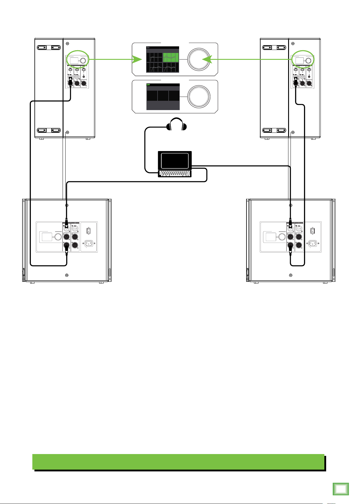
Perhaps you’re a DJ playing bumpin’ tunes in the middle of the night to a crowd that’s groovin’ and dancin’
to your fine selection.
In this example, a laptop is connected to the inputs of two DRM8S subwoofers with the X-Over set to DRM Top.
The High-Pass Out of each subwoofer is then connected to the input of each DRM22 loudspeaker.
Additionally, a set of Mackie MC-250 headphones is connected to the phones jack of the laptop.
INPUT
DIRECT OUT
HIGH-PASS OUT HIGH-PASS OUT
INPUT
DIRECT OUT
100-240VAC
50-60 Hz 110W
The Speaker Modes of both loudspeakers may be set to Club and the Subwoofer HPF set to DRM Sub.
DJ System
Owner’s Manual
7
Page 8
Hookup Diagrams continued...
DRM Professional Powered Loudspeaker Series
To next DRM
loudspeaker
input
GAIN GAIN
U
LINE
INPUT INPUT
To next DRM
loudspeaker
input
SPEAKER CONTROL
SPEAKER CONTROL
SPEAKER CONTROL
SPEAKER CONTROL
Main
PUSH FOR SETTINGS
GAIN
U
MIC
MIC
LINE
+50dBOFF
+50dBOFF
MAXOFF
INPUT
MIX OUTDIRECT OUTDIRECT OUT
GAIN GAIN
U
LINE
INPUT INPUT
PUSH FOR SETTINGS
GAIN
U
MIC
MIC
LINE
+50dBOFF
+50dBOFF
MAXOFF
INPUT
MIX OUTDIRECT OUTDIRECT OUT
Outs
GAIN GAIN
U
LINE
INPUT INPUT
PUSH FOR SETTINGS
GAIN
U
MIC
MIC
LINE
+50dBOFF
+50dBOFF
MAXOFF
INPUT
MIX OUTDIRECT OUTDIRECT OUT
GAIN GAIN
U
LINE
INPUT INPUT
PUSH FOR SETTINGS
GAIN
U
MIC
MIC
LINE
+50dBOFF
+50dBOFF
MAXOFF
INPUT
MIX OUTDIRECT OUTDIRECT OUT
1402VLZ4 Mixer
To next DRM
loudspeaker
input
SPEAKER CONTROL
GAIN GAIN
GAIN
U
U
MIC
LINE
LINE
+50dBOFF
+50dBOFF
INPUT
INPUT INPUT
PUSH FOR SETTINGS
MIC
MAXOFF
MIX OUTDIRECT OUTDIRECT OUT
SPEAKER CONTROL
GAIN GAIN
GAIN
U
U
MIC
LINE
LINE
+50dBOFF
+50dBOFF
INPUT
INPUT INPUT
PUSH FOR SETTINGS
MIC
SPEAKER CONTROL
GAIN GAIN
U
MAXOFF
MIX OUTDIRECT OUTDIRECT OUT
LINE
INPUT INPUT
PUSH FOR SETTINGS
GAIN
U
MIC
MIC
LINE
+50dBOFF
+50dBOFF
MAXOFF
INPUT
MIX OUTDIRECT OUTDIRECT OUT
DRM loudspeakers may be daisy-chained via the male XLR connector labeled “DIRECT OUT” (which sends only
the signal from the input located above it) or via the “MIX OUT” which outputs all inputs. Simply plug the signal
source (i.e., mixer output or microphone) into the input jack(s), and patch that loudspeaker’s direct out or mix
out jack to the next loudspeaker’s input jack, and so on, daisy-chaining multiple DRM loudspeakers. See above
for visual representations of daisy-chaining.
Daisy-Chaining Multiple DRM Loudspeakers
8
DRM Professional Powered Loudspeaker Series
Page 9
Hookup Diagrams continued...
Owner’s Manual
GAIN GAIN
U
LINE
INPUT INPUT
SPEAKER CONTROL
PUSH FOR SETTINGS
SPEAKER CONTROL
SUBWOOFER HPF
DRM SUB
DRM
VAROFF
SUB
SPEAKER CONTROL
PUSH FOR SETTINGS
GAIN
U
MIC
MIC
LINE
+50dBOFF
+50dBOFF
MAXOFF
INPUT
MIX OUTDIRECT OUTDIRECT OUT
INPUT
DIRECT OUT
HIGH-PASS OUT HIGH-PASS OUT
INPUT
DIRECT OUT
100-240VAC
50-60 Hz 110W
INPUT
INPUT
SPEAKER CONTROL
DIRECT OUT
DIRECT OUT
PUSH FOR SETTINGS
HIGH-PASS OUT HIGH-PASS OUT
PUSH FOR SETTINGS
100-240VAC
50-60 Hz 110W
SPEAKER VOICING
LIVE SHOW
LIVE
SPEECH
SPEAKER VOICING
MONITOR POSITION
LIVE
SPEECH
SPEAKER CONTROL
CLUB
MON
SPEAKER CONTROL
CLUB
MON
PUSH FOR SETTINGS
PUSH FOR SETTINGS
SPEAKER CONTROL
PUSH FOR SETTINGS
GAIN GAIN
GAIN
U
U
MIC
MIC
LINE
LINE
+50dBOFF
+50dBOFF
MAXOFF
INPUT INPUT
INPUT
MIX OUTDIRECT OUTDIRECT OUT
INPUT
SPEAKER CONTROL
INPUT
DIRECT OUT
DIRECT OUT
PUSH FOR SETTINGS
HIGH-PASS OUT HIGH-PASS OUT
100-240VAC
50-60 Hz 110W
INPUT
INPUT
SPEAKER CONTROL
DIRECT OUT
DIRECT OUT
PUSH FOR SETTINGS
HIGH-PASS OUT HIGH-PASS OUT
100-240VAC
50-60 Hz 110W
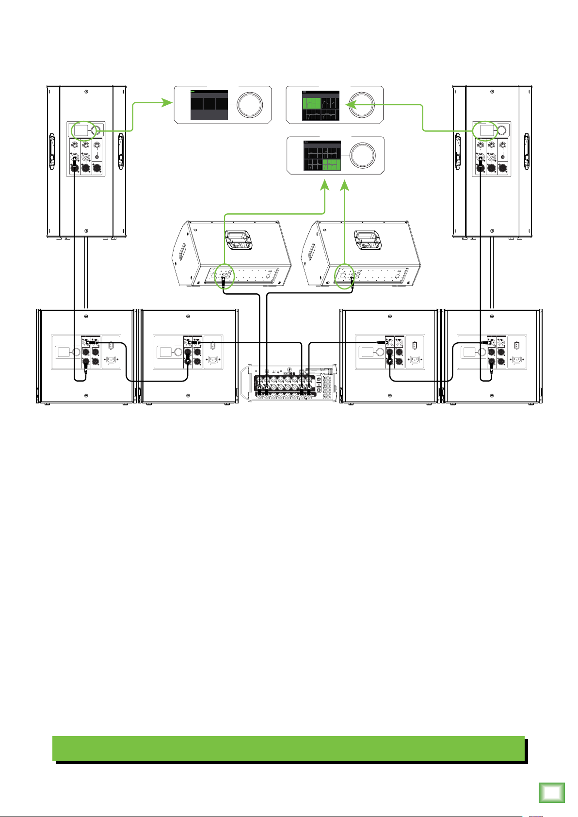
Here’s how to set up a large club system. In this example, the L/R outputs of a DL6S mixer are connected directly
to the CH inputs of a pair of DRM8S subwoofers. The Direct Out of each subwoofer is then connected to the inputs
of an additional pair of DRM8S subwoofers. The X-Over of these subwoofers may be set to DRM Top.
From here, the high-pass outputs of the two outer DRM8S subwoofers are connected directly to the inputs of a set
of DRM35 loudspeakers. The Speaker Modes of these PA loudspeakers may be set to Live (or Club) and the Subwoofer
HPF set to DRM Sub. Talk about beefy low end!
Outputs and 2 from the mixer may be used as aux sends; these are connected directly to the CH inputs of a pair of DRM22
loudspeakers to be used as monitors for the band. The Speaker Modes of the monitor loudspeakers may be set to Monitor.
Large Club System
Owner’s Manual
9
Page 10

DRM Loudspeakers: Rear Panel Features
. Power Connection
This is a standard 3-prong IEC power connector.
Connect the detachable power cord (included in
the packaging with the loudspeaker) to the power
receptacle, and plug the other end of the power
cord into an AC outlet.
Make sure that the AC power is matched to
the AC power indicated on the rear panel
(below the IEC receptacle).
Disconnecting the plug’s ground pin is
dangerous. Don’t do it!
2. Power Switch
Press the top of this rocker switch inwards to turn
on the loudspeaker. Press the bottom of this rocker
switch inwards to turn o the loudspeaker.
As a general guide, the mixer (or other
signal source) should be turned on first,
subwoofers next, and loudspeakers last.
As such, the loudspeakers should also be turned
o first, followed by the subwoofers, then the mixer.
This will reduce the possibility of any turn-on or
turn-o thumps and other noises generated by any
DRM Professional Powered Loudspeaker Series
upstream equipment from coming out of the speakers.
SPEAKER CONTROL
GAIN GAIN
LINE
U
MIC
+50dBOFF
INPUT INPUT
GAIN
U
LINE
4 7
MIC
+50dBOFF
INPUT
3 6
5 8
1
109
PUSH FOR SETTINGS
MAXOFF
MIX OUTDIRECT OUTDIRECT OUT
2
3. XLR and /4" Combo Inputs [Ch. and 2]
Input channels and 2 may accept a balanced
mic signal using an XLR connector. They are wired
as follows, according to standards specified by
the AES (Audio Engineering Society).
XLR Balanced Wiring:
Pin = Shield (ground)
Pin 2 = Positive (+ or hot)
Pin 3 = Negative (– or cold)
SHIELD
COLD
3
In addition to accepting a balanced mic signal
using an XLR connector, these input channels may
also accept /4" line-level signals driven by balanced
or unbalanced sources.
2
HOT
1
3
1
2
SHIELD
COLD
HOT
100-240VAC
50-60 Hz 110W
Also, channel 2 may accept a Hi-Z source (such
as a guitar) via the /4" input without the need for
a separate DI box. Be sure to set the Ch. 2 In to Hi-Z in
the Configuration menu, though! Directions on page 7.
To connect balanced lines to these inputs, use
a /4" Tip-Ring-Sleeve (TRS) plug. “TRS” stands
for Tip-Ring-Sleeve, the three connection points
available on a stereo /4" or balanced phone jack
or plug. TRS jacks and plugs are used for balanced
signals and are wired as follows:
/4" TRS Balanced Mono Wiring:
Sleeve = Shield
Tip = Hot (+)
Ring = Cold (–)
TIPSLEEVE
SLEEVERING
TIP
RING
RING
TIP
SLEEVE
10
DRM Professional Powered Loudspeaker Series
Page 11

DRM Loudspeakers: Rear Panel Features continued...
SLEEVE
Owner’s Manual
To connect unbalanced lines to these inputs,
use a /4" mono (TS) phone plug, wired as follows:
/4" TS Unbalanced Mono Wiring:
Sleeve = Shield
Tip = Hot (+)
SLEEVE
TIP
TIPSLEEVE
TIP
NEVER connect the output of an amplifier
directly to a DRM’s input jack. This could
damage the input circuitry!
4. Gain [Ch. and 2]
The gain knobs adjust the input sensitivity
of the mic/line inputs. This allows signals from
the outside world to be adjusted to run through
each channel at optimal internal operating levels.
There is –
(o), ramping up to +50 dB of gain fully up (max).
dB of gain with the knob fully down
If connecting mixer outputs to loudspeaker
inputs, set the gain knob to 0:00 [“U”]
for optimal sound and performance.
6. /8" Input [Ch. 3/4]
This input may accept a stereo /8" line-level signal
from a phone, tablet, MP3 player, or other signal
source.
NEVER connect the output of an amplifier
directly to this input jack. This could damage
the input circuitry.
7. Gain [Ch. 3/4]
This gain knob adjusts the input sensitivity
of the /8" stereo input. This allows signals from
the outside world to be adjusted to run at optimal
internal operating levels. It ranges from o (knob
fully down) up to max (knob fully up).
8. Mix Out
This is a male XLR-type connector that produces
the post-DSP mix – afer voicing mode and EQ, but
before the alignment delay – from all three input jacks
(with Ch. 3/4 mono-summed). Use it to daisy-chain
several DRM loudspeakers together o the same
signal source(s).
It is wired the same as the direct outputs as seen
to the lef.
5. Direct Out [Ch. and 2]
This is a male XLR-type connector that produces
exactly the same signal that is connected to the input
jack located above it. Use it to daisy-chain several DRM
loudspeakers together o the same signal source(s).
They are wired as follows, according to standards
specified by the AES (Audio Engineering Society):
Balanced XLR Output Connector
Pin – Shield (ground)
Pin 2 – Positive (+ or hot)
Pin 3 – Negative (– or cold)
SHIELD
1
3
COLD
See page 8 to learn more about daisy-chaining
DRM loudspeakers.
2
HOT
1
3
2
SHIELD
COLD
HOT
9. LCD Display
This modern, high-resolution, all-color TFT LCD
Display is one of the most vital features of the DRM
loudspeaker. It displays loudspeaker information
including (but not limited to) levels, EQ, selected
voicing, settings, lock / unlock status and other
parameters.
The brightness is controllable, but
an overall screen brightness is required
for certain aspects of the set-up options.
SPEAKER CONTROL
Voicing Mode :
1 2 3 Main
Live
Subwoofer :
DRM SUB
Low: Mid: High:
+6
130-71.25k
Delay :
+10
15.5k
9 ms
109
-22Lo-Z
PUSH FOR SETTINGS
0. Speaker Control Knob
This push-button rotary encoder allows you to access
functions such as channel and master level control
and metering, application specific voicings & EQ, setup
functions, product information and much more!
Owner’s Manual
11
Page 12

DRM Control Dashboard™
1 2 3 Main
CONFIG
1 2 3 Main
CONFIG
The following list provides the high level navigation
items, in order, on the user interface and their
subsequent user controlled parameters.
The default screen is the main view, as seen below:
Main – This displays the I/O metering, voicing
mode, subwoofer HPF selection, EQ and delay
settings and more. The only thing that may
be changed here is the main output level.
Voicing Mode :
Live
Subwoofer :
DRM SUB
Low: Mid: High:
+6
130-71.25k
Delay :
9 ms
Menu – The menu provides icon selectors
for all user-controllable functions with most
of these containing an array of sub-menus.
DRM Professional Powered Loudspeaker Series
Main
Mode
+10
15.5k
-22Lo-Z
Sub
Main
Push the speaker control knob to open the menu.
From here, rotate the speaker control knob to scroll
between the six selections. The current selection will
illuminate in a can’t-miss DayGlo green.
The first choice here is main. Push the button when
main is illuminated to open it.
Voicing Mode :
Live
Subwoofer :
DRM SUB
Low: Mid: High:
+6
130-71.25k
Delay :
9 ms
+10
15.5k
-22Lo-Z
As you can see here, this is the same exact look as
the default main screen. Like the default main screen,
here you can only update the main output level. Do so
by turning the speaker control knob clockwise (louder)
and counter-clockwise (quieter). Once the level you
desire has been dialed in, press the speaker control
knob again to return to the main screen.
The main level control range is as follows:
• Main Output: – dB (o) to 0 dB (U, max)
MAIN
EQ DELAY
EQ
We will go through each, how to get there and how
to change settings.
Afer a selection is made, the LCD screen will revert
back to the Main screen afer 5 seconds of (speaker
control) inactivity. You yourself may continue to be
as active (or inactive)as you want.
Rotate the speaker control knob to navigate between
the selections and push the button to open and edit
the parameters.
MODE SUB
Delay
Config
Speaker Mode
Speaker mode allows you to change the
loudspeaker’s speaker voicing to tailor it
to best suit your particular application.
MAIN
EQ DELAY
MODE
SUB
The four speaker modes are as follows:
• Live – This mode is flat, perfect
for singer-songwriters and other live performers.
• Club – This mode is full range, but focuses
on increased bass and brilliant high frequencies.
This is the place to start for most DJ / music
playback applications.
12
DRM Professional Powered Loudspeaker Series
Page 13

• Speech – This mode features a significant low
SPEAKER VOICING
SPEAKER VOICING
CONFIG
frequency roll-o to get rid of unwanted thumps.
It also adds boost and sparkle to mid-range and high
frequencies, critical for speech applications.
This plug-and-play mode is perfect for larger venue
applications where speech is the primary audio
source in need of clear and precise intelligibility.
Sub
Owner’s Manual
You’re our hero, so we have a built-in submarine
sandwich maker! Afer pushing the speaker control
knob in to select sub, you will be presented with
a multitude of choices, including:
• Cold Cut
• Roast Beef
• Monitor – This mode features a low frequency
roll-o and a reduction around 2 kHz to ensure
maximum gain before feedback in monitor applications.
MONITOR POSITION
LIVE
SPEECH
MONITOR POSITION
LIVE
CLUB
MON
CLUB
• Philly Cheesesteak
• BLT
• Meatball
• Veggie
• Tuna
• Design Your Own
Now that you’re hungry, let’s take a look at what
opening the sub menu really displays:
• O – Choose this if there is no subwoofer
connected to the system. Here you are using
DRM loudspeakers only.
• DRM Sub – Choose this if a Mackie DRM8S
subwoofer is connected to the system. The crossover
point is set to 90 Hz to work in perfect harmony with
the Mackie DRM8S Sub. This is what we hope you
choose, thank you for your support!
SPEECH
Simply rotate the speaker control knob until
the speaker mode you desire is illuminated, then
push to select it. As seen above, we selected Monitor.
In addition to the four speaker modes, there’s a fifh
and final selection: the lef-facing arrow. Illuminating
and selecting this simply returns you to the menu.
MON
MAIN
EQ DELAY
• Var – Choose this if a non-Mackie DRM8S
subwoofer is connected to the system. Here you
can select the subwoofer’s HPF, ranging from
40 Hz – 60 Hz.
MODE SUB
Owner’s Manual
13
Page 14

Rotate the speaker control knob until the sub HPF
SUBWOOFER HPF
SUBWOOFER HPF
CONFIG
EQ FLAT
EQ FLAT
you desire is illuminated, then push to select it.
If var is selected (as seen below), the frequency
is illuminated and may be changed by rotating the
speaker control knob clockwise (raise the frequency)
and counter-clockwise (lower the frequency).
VAR
DRM
VAROFF
SUB
90Hz
The DRM22, DRM25 and DRM35 all have 3-band
EQ with shelving hi, peaking mid and shelving low.
Shelving means that the circuitry boosts or cuts all
frequencies past the specified frequency. Peaking
means that certain frequencies form a “hill” around
the center frequency.
With too much EQ, you can really upset
things. We’ve designed a lot of boost
and cut into the equalizer circuit because
we know that everyone will occasionally need that.
But if you max the EQ, you’ll get mix mush.
In order to change the EQ, first push the speaker
control knob when the EQ icon is illuminated
(see image above). This opens the EQ view:
VAR
DRM
VAROFF
SUB
DRM Professional Powered Loudspeaker Series
90Hz
In addition to the three sub modes, there’s a fourth
and final selection: the lef-facing arrow. Illuminating
and selecting this simply returns you to the menu.
EQ Setup
On to the bottom row now! The first one listed
is EQ, and, as you might expect, this is where
to adjust the output EQ.
LoShelf
+7
133
From here, rotate the speaker control knob until
the parameter you want to change is illuminated.
Push the speaker control knob in to select the
parameter followed by rotating the speaker control
knob clockwise (raise the gain / frequency)
and counter-clockwise (lower the gain / frequency).
LoShelf
+7
133
-6
1.27k
-6
1.27k
HiShelfMidPar
+8
15.4k
HiShelfMidPar
+8
15.4k
14
DRM Professional Powered Loudspeaker Series
MAIN
EQ DELAY
MODE
SUB
The EQ ranges are as follows:
• Low: ±2 dB @ 20 Hz – 200 Hz
• Mid: ±2 dB @ 200 Hz – 2.00 kHz
• High: ±2 dB @ 2.00 kHz – 20.0 kHz
Page 15

In addition to these EQ choices, there are two more
EQ
FLAT
CONFIG
DELAY
DELAY
selections. First, when flat is illuminated and selected
(by pushing in the speaker control knob), the EQ resets
to flat:
• Low: ±0 dB (unity) @ 00 Hz
• Mid: ±0 dB (unity) @ .00 kHz
• High: ±0 dB (unity) @ 0.0 kHz
LoShelf
HiShelfMidPar
The delay time ranges from a low of 0.0 ms (f, m)
Owner’s Manual
to a maximum of 00 ms (2.5 f, 34.2 m).
In order to change the delay, first push the speaker
control knob when the delay icon is illuminated (see
image above). This opens the delay view.
From here, rotate the speaker control knob clockwise
until the ms parameter is highlighted.
This is the only parameter that can
be changed here; the f and m delay time
ranges update automatically dependent
on where ms is set.
+7
133
Like the previous sub-menus, the EQ also has
a lef-facing arrow. Illuminating and selecting
this simply returns you to the menu.
Let’s talk about those meters now.
That is what’s called a “Real-Time Analyzer”
[RTA for short]. It measures and displays
the sound of the corresponding output – amplitude
versus frequency components of a continuous
signal – via DSP.
An RTA allow you to see what you hear so you
may easily locate and eliminate feedback and other
anomalies while seeing the EQ changes in real time.
Many audio signals are highly dynamic: music,
speech and even environmental noise contain
significant changes in spectral content as a function
of time. With a digital mixer, musicians and sound
engineers can save time setting up at shows by
recalling previous settings. The DRM’s RTA fits right
in with that, literally displaying frequencies, shortening
the time it takes to tune the main loudspeakers or stage
monitors during setup in a new room.
There are 5 bands on all DRM Series RTAs.
-6
1.27k
+8
15.4k
Push the speaker control knob in to select
the ms parameter followed by rotating the speaker
control knob clockwise (raise the delay time )
and counter-clockwise (lower the delay time).
ms
9
9
ft
m
ms
ft
m
10.1
3.0
10.1
3.0
Delay
Probably the easiest parameter to describe
and update. This controls the monitor delay.
In other words, you are going to want to time-align
the speakers throughout the venue so the sound
hits everywhere simultaneously. This is the place.
MAIN
EQ
MODE
DELAY
SUB
Like the previous sub-menus, the delay also
has a lef-facing arrow. Illuminating and selecting
this simply returns you to the menu.
Owner’s Manual
15
Page 16

Configuration
CONFIGURATION
CONFIGURATION
CONFIGURATION
CONFIGURATION
This is where to recall / store settings to memory,
lock access to the settings, select Ch. 2 input setting
and more.
There are six user memory snapshots which should
be more than enough.
Store – Tap this to store the current settings
to the corresponding memory snapshot.
Please be aware that the new settings
will replace the currently saved settings.
MAIN
EQ DELAY
This is similar to what you will see afer first entering
the configuration screen. The current Ch2 in, backlight
and front LED settings will be illuminated.
MEMORY 1 2 3 4 5 6
LOCK PIN 1 2 3 4
CH2 IN LO-Z HI-Z
BACKLIGHT
FRONT LED
RESET
ABOUT
DRM Professional Powered Loudspeaker Series
To change a setting, just rotate the speaker
control knob until the configuration you desire
to change is illuminated, then push to select it.
MODE SUB
CONFIG
OFF DIM ON
OFF ON
Recall – Tap this to recall the settings of the selected
memory snapshot.
Illuminating and selecting the lef-facing arrow
returns you to the previous screen.
Lock Pin – This is where to lock and unlock the
interface with a secret 4-digit numeric password.
Rotate the speaker control knob until lock pin
is illuminated, then push in to enter lock mode.
From here, rotate the speaker control knob until
the first number you desire is illuminated and press
to select. Follow the same procedure for the next
three numbers.
As seen below, we decided to go with -2-3-4 because
that’s (a “5” shy of) the same code that was used
on Spaceballs. A confirmation dialog helps prevent
accidents. No further changes may be made until
the control access is unlocked.
These are the choices from top to bottom:
Memory – When memory is selected, settings may be
saved to memory and recalled at a later time. No more
having to reset levels, EQ, voicing, etc. upon every
power-up.
MEMORY 1 2 3 4 5 6
LOCK PIN 1 2 3 4
CH2 IN LO-Z HI-Z
BACKLIGHT
FRONT LED
RESET
ABOUT
MEMORY 1 2 3 4 5 6
LOCK PIN 1 2 3 4
CH2 IN LO-Z HI-Z
BACKLIGHT
RECALL STORE
FRONT LED
RESET
ABOUT
CONFIGURATION
User memory
OFF DIM ON
MEMORY
3:
OFF DIM ON
OFF ON
OFF ON
MEMORY 1 2 3 4 5 6
LOCK PIN 1 2 3 4
CH2 IN LO-Z HI-Z
BACKLIGHT
FRONT LED
RESET
ABOUT
MEMORY 1 2 3 4 5 6
LOCK PIN 1 2 3 4
CH2 IN LO-Z HI-Z
BACKLIGHT
FRONT LED
RESET
ABOUT
Unlocking – If you try to make any changes
or select anything, you will be asked to enter
the pin. Here you will need to re-enter the 4-digit
code and push the speaker control knob to unlock.
YES NO
OFF DIM ON
LOCK
Lock user
interface?
OFF DIM ON
OFF ON
OFF ON
16
DRM Professional Powered Loudspeaker Series
Page 17

Secret Squirrel Unlock – If you – or worse, someone
CONFIGURATION
CONFIGURATION
CONFIGURATION
CONFIGURATION
CONFIGURATION
CONFIGURATION
else! – set up a 4-digit lock code and you don’t know
the passcode, there is a quick fix. Simply press and
hold down the speaker control knob down for a few
seconds and it will automatically unlock.
Illuminating and selecting the lef-facing arrow
returns you to the previous screen.
Ch 2 in – The channel 2 input allows instruments
to be connected directly into the /4" jack. To connect
an instrument directly without using a DI Box, change
the channel 2 input setting to Hi-Z first. The Hi-Z text
will illuminate to indicate that Hi-Z is active. Then
connect the output from the instrument to the
channel 2 /4" TRS input. The input impedance
is optimized for direct connection and high-frequency
fidelity is assured.
Guitars may sound dull and muddy without a DI box
or if Hi-Z is not engaged. When set at Lo-Z, the channel
2 /4" TRS input become a line input.
Front LED – Decide if you want the front LED
on or o. When illuminated, push the speaker
control knob to select between on or o.
MEMORY 1 2 3 4 5 6
LOCK PIN 1 2 3 4
CH2 IN LO-Z HI-Z
BACKLIGHT
FRONT LED
RESET
ABOUT
Like the previous sub-menus, configuration also
has a lef-facing arrow. Illuminating and selecting
this simply returns you to the menu.
Reset – Resets all parameters back to their factory
default. This is a permanent reset with no undo,
so a confirmation dialog helps prevent accidents.
OFF DIM ON
OFF ON
Owner’s Manual
MEMORY 1 2 3 4 5 6
LOCK PIN 1 2 3 4
CH2 IN LO-Z HI-Z
BACKLIGHT
FRONT LED
RESET
ABOUT
Illuminating and selecting the lef-facing arrow
returns you to the previous screen.
More information about channel 2’s Hi-Z
input may be found on page 0.
Backlight – The fourth configuration setting
that may be changed is the brightness – or lack
thereof – of the LCD screen.
There are three choices: o, dim and on.
OFF DIM ON
OFF ON
MEMORY 1 2 3 4 5 6
LOCK PIN 1 2 3 4
CH2 IN LO-Z HI-Z
BACKLIGHT
FRONT LED
RESET
ABOUT
MEMORY 1 2 3 4 5 6
LOCK PIN 1 2 3 4
CH2 IN LO-Z HI-Z
BACKLIGHT
FRONT LED
RESET
ABOUT
Factory reset
Keep presets?
OFF DIM ON
OFF ON
RESET
OFF DIM ON
YES
NO
OFF ON
MEMORY 1 2 3 4 5 6
LOCK PIN 1 2 3 4
CH2 IN LO-Z HI-Z
BACKLIGHT
Illuminating and selecting the lef-facing arrow
returns you to the previous screen.
FRONT LED
RESET
ABOUT
OFF DIM ON
OFF ON
MEMORY 1 2 3 4 5 6
LOCK PIN 1 2 3 4
CH2 IN LO-Z HI-Z
BACKLIGHT
FRONT LED
RESET
ABOUT
RESET
Confirm factory
reset?
OFF DIM ON
YES
NO
OFF ON
Owner’s Manual
17
Page 18

The screen displayed on the previous
CONFIGURATION
CONFIGURATION
ABOUT
page and again below may be of particular
interest. Yes, it’s true – you CAN do
a factory reset and either choose to
save your user presets or not!
MEMORY 1 2 3 4 5 6
LOCK PIN 1 2 3 4
CH2 IN LO-Z HI-Z
BACKLIGHT
FRONT LED
RESET
ABOUT
Illuminating and selecting the lef-facing arrow
returns you to the previous screen.
RESET
Factory reset
Keep presets?
OFF DIM ON
YES
NO
OFF ON
Protection Circuitry
DRM loudspeakers employ a built-in limiter for less
distortion at peak levels. A dynamic bass response
circuit provides optimal low frequency response regardless of overall output level. Additional protection
includes automatic thermal shutdown should the amp
overheat. However, with Class-D amp technology, which
is highly-ecient, this should never be a problem.
The protection circuits are designed to
protect the loudspeakers under reasonable
and sensible conditions. Should you choose
to ignore the warning signs [e.g. excessive distortion],
you can still damage the speaker in the loudspeaker
by overdriving it past the point of amplifier clipping.
Such damage is beyond the scope of the warranty.
About – Displays the current information about your
loudspeaker, including the model, firmware and DSP
versions, temperature and favorite color. There is really
only one reason to go here and that is if you’ve been
directed so by Technical Support.
MEMORY 1 2 3 4 5 6
DRM Professional Powered Loudspeaker Series
LOCK PIN 1 2 3 4
CH2 IN LO-Z HI-Z
BACKLIGHT
FRONT LED
RESET
ABOUT
FW : DRM212 v1.0.29
DSP : DRM212 v111
TEMP : 29˚C / 85˚F
OFF DIM ON
OFF ON
Limiting
The driver has its own compression circuit which
helps protect it from damaging transient peaks.
The compressor is designed to be transparent and
is not noticeable under normal operating conditions.
Overexcursion Protection
A subsonic filter circuit just prior to the power
amplifier prevents ultra-low frequencies from being
amplified. Excessive low-frequency energy can damage
the woofer by causing it to “bottom out,” also know
as overexcursion, which is equivalent to a mechanical
form of clipping.
Thermal Protection
All amplifiers produce heat. DRM loudspeakers are
designed to be ecient both electrically and thermally.
In the unlikely event of the amplifier overheating, a
built-in thermal switch will activate, muting the signal.
When the amplifier has cooled down to a safe
operating temperature, the thermal switch resets
itself, and the DRM loudspeaker resumes normal
operation.
18
DRM Professional Powered Loudspeaker Series
If the thermal switch activates, try turning down
the level control a notch or two on the mixing console
(or via the Speaker Control knob) to avoid overheating
the amplifier. Be aware that direct sunlight and/or
hot stage lights may be the culprit of an amplifier
overheating.
Page 19

AC Power
Owner’s Manual
Placement
Be sure the DRM loudspeaker is plugged into
an outlet that is able to supply the correct voltage
specified for your model. It will continue to operate
at lower voltages, but will not reach full power. Be sure
the electrical service can supply enough amperage for
all the components connected to it.
We recommend that a sti (robust) supply of AC
power be used because the amplifiers place high
current demands on the AC line. The more power that
is available on the line, the louder the speakers will play
and the more peak output power will be available for
a cleaner, punchier bass. A suspected problem of “poor
bass performance” is ofen caused by a weak AC supply
to the amplifiers.
Never remove the ground pin on the power
cord or any other component of the DRM
loudspeaker. This is very dangerous.
Care and Maintenance
Your DRM loudspeakers will provide many years
of reliable service if you follow these guidelines:
• Avoid exposing the loudspeakers to moisture.
If they are set up outdoors, be sure they are under
cover if rain is expected.
• Avoid exposure to extreme cold (below freezing
temperatures). If you must operate the loudspeakers
in a cold environment, warm up the voice coils slowly
by sending a low-level signal through them for about
5 minutes prior to high-power operation.
WARNING: Installation should only
be done by an experienced technician.
Improper installation may result in damage
to the equipment, injury or death. Make sure that
the loudspeaker is installed in a stable and secure
way in order to avoid any conditions that may be
dangerous for persons or structures.
DRM loudspeakers are designed to sit on the floor or
stage as the main PA or as monitors. They may also be
pole-mounted via the built-in socket on the bottom of
the cabinet. Be sure the pole is capable of supporting
the weight of the loudspeaker. The SPM400 is a great
option when using a subwoofer.
These loudspeakers may also be flown via their
integrated fly points as detailed on the following
pages. Be sure to read the PA-A2 Eyebolt Installation
Instructions, as well.
NEVER attempt to suspend a DRM
loudspeaker by its handles.
Check to make sure that the support surface
(e.g. floor, etc.) has the necessary mechanical
characteristics to support the weight of the
loudspeaker(s).
When pole-mounting loudspeakers, be sure that they
are stabilized and secured from falling over or being
accidentally pushed over. Failure to follow these
precautions may result in damage to the equipment,
personal injury, or death.
The DRM22 and DRM25 have dual angle
pole-mounts for optimal coverage. The rear one
is a straight angle while the front is angled at a 7˚
downward tilt. Additionaly, these two models may
be laid out horizontally as monitors for the band
at a 50˚ angle (as seen below).
• Use a dry cloth to clean the cabinets. Only
do this when the power is turned o. Avoid getting
moisture into any of the openings of the cabinet,
particularly where the drivers are located.
The Running Man logo is rotatable for
when the DRM22 or DRM25 is used
as a monitor; you can also rotate it when
the DRM35 is flown horizontally!
As with any powered components, protect them from
moisture. Avoid installing the loudspeaker in places
exposed to harsh weather conditions. If you are setting
them up outdoors, make sure they are under cover if
you expect rain.
Owner’s Manual
19
Page 20

Room Acoustics
REARBOTTOMTOP SIDE
DRM loudspeakers are designed to sound fantastic
in nearly every application.
But, room acoustics play a crucial role in the overall
performance of a sound system. However, the wide
high-frequency dispersion of the DRM loudspeakers
helps to minimize the problems that typically arise.
Here are some additional placement tips to help
overcome some typical room problems that might arise:
• Placing loudspeakers in the corners of a room
increases the low frequency output and can cause
the sound to be muddy and indistinct.
• Placing loudspeakers against a wall increases
the low frequency output, though not as much
as corner placement. However, this is a good way
to reinforce the low frequencies, if so desired.
• Avoid placing the speakers directly on a hollow
stage floor. A hollow stage can resonate at certain
frequencies, causing peaks and dips in the frequency
response of the room. It is better to place them
on a sturdy stand designed to handle the weight
of the loudspeaker.
• Position the loudspeakers so the high-frequency
drivers are two to four feet above ear level for
the audience (making allowances for an audience
that may be standing/dancing in the aisles).
DRM Professional Powered Loudspeaker Series
High frequencies are highly directional and tend
to be absorbed much easier than lower frequencies.
By providing direct line-of-sight from the loudspeakers
to the audience, you increase the overall brightness
and intelligibility of the sound system.
• Highly reverberant rooms, like many gymnasiums
and auditoriums, are a nightmare for sound system
intelligibility. Multiple reflections o the hard walls,
ceiling, and floor play havoc with the sound. Depending
on the situation, you may be able to take some steps
to minimize the reflections, such as putting carpeting
on the floors, closing draperies to cover large glass
windows, or hanging tapestries or other materials
on the walls to absorb some of the sound.
However, in most cases, these remedies are not
possible or practical. So what do you do? Making
the sound system louder generally doesn’t work
because the reflections become louder, too.
The best approach is to provide as much direct sound
coverage to the audience as possible. The farther away
you are from the speaker, the more prominent will be
the reflected sound.
Use more speakers strategically placed so they
are closer to the back of the audience. If the distance
between the front and back speakers is more than
about 00 feet, you should use either () the internal
delay processor via the speaker control knob (see
page 5), or (2) use an external delay processor
to time-align the sound. (Since sound travels about
foot per millisecond, it takes about /0 of a second
to travel 00 feet.)
Keep in mind that the speaker mode is another great
way to compensate for some of these issues. See page
2 for more information.
MP MP MP
MPMP MP
MP MP MP MP
MPMP
MP
MP = Mounting Point
DRM22 / DRM25 Fly Points
MP MP
DRM35 Fly Points
MP MP
20
REARBOTTOMTOP SIDE
DRM Professional Powered Loudspeaker Series
Page 21

Rigging
WARNING: Installation should only be done
by an experienced technician. Improper
installation may result in damage to the
equipment, injury or death. Make sure that the
loudspeaker is installed in a stable and secure way
in order to avoid any conditions that may be dangerous
for persons or structures.
WARNING: The cabinet is suitable for rigging
via its fly points. NEVER attempt to suspend
a DRM loudspeaker by its handle.
The fly points of the DRM22, DRM25 and DRM35
are shown on the previous page while examples
of a flown DRM315 are displayed below.
The DRM315 may be flown horizontally or
vertically, but the DRM212 and DRM215 may
only be flown vertically.
Rigging Design Practices
Rigging a loudspeaker requires determining:
. The rigging methods and hardware that
meet static, shock, dynamic, and any other load
requirements for supporting the loudspeaker
from structure.
2. The design factor and required WLL (Working
Load Limit) for this support.
We strongly recommend the following rigging
practices:
. Documentation: Thoroughly document the design
with detailed drawings and parts lists.
Owner’s Manual
Rigging Hardware and Accessories
Rigging our loudspeakers will invariably require
hardware not supplied by us. Various types of
load-rated hardware are available from a variety
of third-party sources. There are a number of such
companies specializing in manufacturing hardware
for designing and installing rigging systems. Each
one of these tasks is a discipline in its own right.
Because of the hazardous nature of rigging work
and the potential liability, engage companies that
specialize in these disciplines to do the work required.
We do oer certain accessory rigging items and some
of them may be used with a variety of products. While
these accessories are intended to facilitate installation,
the wide variety of possible installation conditions and
array configurations do not permit us to determine their
suitability or load rating for any particular application.
We are not in the business of providing complete
rigging systems, either as designers, manufacturers,
or installers. It is the responsibility of the installer to
provide a properly engineered, load-certified rigging
system for supporting the loudspeaker from structure.
DRM loudspeakers may be individually
flown using a PA-A2 Eyebolt Kit, part
number 0028272.
Rigging Notes
The DRM loudspeaker’s integral mounting
points are designed to support only the weight
of their own loudspeaker with suitable, external
hardware. This means that each DRM loudspeaker
must be supported independently of any other DRM
loudspeaker and any other loads. At least three rigging
points must be used to hang each DRM loudspeaker.
2. Analysis: Have a qualified professional, such
as a licensed Professional Engineer, review and
approve the design before its implementation.
3. Installation: Have a qualified professional rigger
do the installation and inspection.
4. Safety: Use adequate safety precautions
and back-up systems.
Owner’s Manual
21
Page 22

Appendix A: Service Information
If you think your DRM loudspeaker has a problem,
please check out the following troubleshooting tips
and do your best to confirm the problem. Visit the Support
section of our website (www.mackie.com/support) where
you will find lots of useful information such as FAQs
and other documentation. You may find the answer
to the problem without having to part with your loudspeaker.
Troubleshooting
No power
• Our favorite question: Is it plugged in? Make sure
the AC outlet is live [check with a tester or lamp].
• Our next favorite question: Is the power switch on?
If not, try turning it on.
• Make sure the line cord is securely seated in the line
cord socket and plugged all the way into the AC outlet.
• Is the power LED on the front panel illuminated?
If not, make sure the AC outlet is live. If so, refer
to “No sound” below.
DRM Professional Powered Loudspeaker Series
• The internal AC line fuse may be blown. This is not
a user serviceable part. If you suspect the AC line
fuse is blown, please see the "Repair" section next.
Noise
• Make sure all connections to the loudspeakers
are good and sound.
• Make sure none of the signal cables are routed near
AC cables, power transformers, or other EMI-inducing
devices.
• Is there a light dimmer or other SCR-based device
on the same AC circuit as the DRM loudspeaker?
Use an AC line filter or plug the loudspeaker into
a dierent AC circuit.
Hum
• Try disconnecting the cable connected to the input
jack. If the noise disappears, it could be a “ground
loop,” rather than a problem with the DRM
loudspeaker. Try some of the following troubleshooting
ideas:
• Use balanced connections throughout your
system for the best noise rejection.
• Whenever possible, plug all the audio
equipment’s line cords into outlets which share
a common ground. The distance between
the outlets and the common ground should
be as short as possible.
No sound
• Is the level knob for the input source turned all the way
down? Verify that all the volume controls in the system
are properly adjusted. Look at the level meter
to ensure that the mixer is receiving a signal.
• Is the signal source working? Make sure
the connecting cables are in good repair and securely
connected at both ends. Make sure the output level
control on the mixing console is turned up suciently
to drive the inputs of the speaker.
• Make sure the mixer does not have a mute on
or a processor loop engaged. If you find something
like this, make sure the level is turned down before
disengaging the oending switch.
• Has it shut down? Make sure there is at least six
inches of free space behind each DRM loudspeaker.
Poor sound
• Is it loud and distorted? Make sure that you’re not
overdriving a stage in the signal chain. Verify that
all level controls are set properly.
• Is the input connector plugged completely into
the jack? Be sure all connections are secure.
Other Issues
• Please email or call Technical Support if you
are having any other issue not listed here:
o mackie.com/suppor t-contact
o - 800-898-32
Repair
For warranty service, refer to the warranty information
on page 27.
Non-warranty service is available at a factory-authorized
service center. To locate the nearest service center, visit
www.mackie.com/support/service-locator. Service
for DRM loudspeakers living outside the United States
may be obtained through local dealers or distributors.
If you do not have access to our website, please call
our Tech Support department at -800-898-32 (normal
business hours, Pacific Time), to explain the problem.
They will tell you where the nearest factory-authorized
service center is located in your area.
22
DRM Professional Powered Loudspeaker Series
Page 23

Appendix B: Technical Information
DRM Loudspeakers Specifications
Owner’s Manual
Acoustic Performance
Frequency Range (–0 dB): 45 Hz – 20 kHz [DRM22]
43 Hz – 20 kHz [DRM25]
35 Hz – 20 kHz [DRM35]
Frequency Range (–3 dB): 50 Hz – 20 kHz [DRM22]
47 Hz – 20 kHz [DRM25]
39 Hz – 20 kHz [DRM35]
Horizontal Coverage Angle: 90º [All, DRM35 rotatable]
Vertical Coverage Angle: 60º [All, DRM35 rotatable]
Maximum SPL Peak: 34 dB [DRM22]
35 dB [DRM25]
37 dB [DRM35]
Monitor Angle 50˚ [DRM22 and DRM25]
Transducers
Low Frequency: 2 in / 305 mm [DRM22]
5 in / 38 mm [DRM25 and DRM35]
with ferrite
Mid Frequency: 6.5 in / 65 mm [DRM35]
High Frequency: .4 in / 36 mm titanium
dome compression driver [All]
Power Amplifiers
System Power Amplification
Rated Power 600 watts peak [DRM22]
600 watts peak [DRM25]
2300 watts peak [DRM35]
Low Frequency Power Amplifier
Rated Power: 220 watts peak [DRM22]
220 watts peak [DRM25]
920 watts peak [DRM35]
Rated THD < %
Cooling Convection
Design: Class D
High Frequency Power Amplifier
Rated Power: 380 watts peak
Rated THD < %
Cooling Convection
Design: Class D
System Processing
Voicing 4 speaker modes
Subwoofer HPF O, DRM8S, Var
Main Output EQ 3-band
Delay 0 – 00 ms
Equalization
Low ±2 dB @ 20 Hz – 200 Hz
Mid ±2 dB @ 200 Hz – 2.00 kHz
High ±2 dB @ 2.00 kHz – 20.0 kHz
HPF 40 Hz – 60 Hz (Var)
Input/Output
Input Type: 2x Female XLR Balanced
• /4" Balanced • /8" Stereo
Mic-Line Impedance: 8 k
1/4" TS, Wide-Z™ Impedance: M
Direct Out and Mix Out: Male XLR Balanced
Mix Out Impedance: 600
Main Control: Rotating knob
balanced
unbalanced
balanced
Electronic Crossover
Crossover Type: 24 dB/octave
Crossover Frequency: .5 kHz [DRM22 and DRM25]
900 Hz [DRM35 LF / MF]
2.5 kHz [DRM35 MF / THF]
Line Input Power
Detachable line cord ~00 – 240 VAC, 50 – 60 Hz, 0W
~220 – 240 VAC, 50 – 60 Hz, 0W
AC Connector 3-pin IEC 250 VAC, 0 A male
Power Supply Type Switchmode
Safety Features
Input Protection Peak and RMS limiting,
power supply and amplifier
thermal protection
Display LEDs Defeatable front power,
Speaker Control
Status Info Input and output levels, voicing mode,
sub HPF, EQ and delay settings
Construction Features
Basic Design: Asymmetrical [DRM22 and DRM25]
Vertical Trapezoidal [DRM35]
Enclosure Material: Plywood
Enclosure Finish: Black Polyurea
Grille Material: 6-8 gauge perforated steel
Grille Finish: Powder-coated black
Handles: One on each side [All],
one on top[DRM22 and DRM25]
Display LEDs
Front: Power ON
Rear: Speaker Control
Operating Temperature: 0 – 40 ˚C
32 – 104 ˚F
Owner’s Manual
23
Page 24

DRM Loudspeakers Specifications continued...
Physical Properties
DRM22:
Height: 25.0 in / 635 mm
Width: 4.7 in / 373 mm
Depth: 6.2 in / 4 mm
Weight: 42.0 lb / 9. kg
DRM25:
Height: 28.3 in / 79 mm
Width: 8. in / 460 mm
Depth: 7.0 in / 432 mm
Weight: 57.0 lb / 25.9 kg
DRM35:
Height: 36.5 in / 927 mm
Width: 9.0 in / 483 mm
Depth: 8.8 in / 478 mm
Weight: 68.0 lb / 30.8 kg
Mounting Methods:
Floor mount, pole mount via the built-in socket on the bottom of
the cabinet [Be sure the pole is capable of supporting the weight
of the DRM loudspeaker] or fly via the integrated M0 mounting
points (using M0 x .5 x 20 mm forged shoulder eyebolts).
DRM Professional Powered Loudspeaker Series
See pages 9-2 for more information.
Options
DRM22 Cover P/N 2036809-48
DRM25 Cover P/N 2036809-49
DRM35 Cover P/N 2036809-50
SPM400 Loudspeaker Pole Mount P/N 205055
PA-A2 Forged Shoulder Eyebolt Kit
(3 x M0 x .5 x 20 mm) P/N 0028272
Disclaimer
Since we are always striving to make our products better
by incorporating new and improved materials, components,
and manufacturing methods, we reserve the right to change
these specifications at any time without notice.
The “Running Man” figure is a registered trademark of LOUD
Audio, LLC.
All other brand names mentioned are trademarks or registered
trademarks of their respective holders, and are hereby
acknowledged.
©209 LOUD Audio, LLC.
All Rights Reserved.
24
DRM Professional Powered Loudspeaker Series
Page 25

DRM22 Loudspeaker Dimensions
411 mm
478 mm
483 mm
WEIGHT
42.0 lb
19.1 kg
25.0 in
635 mm
Owner’s Manual
DRM25 Loudspeaker Dimensions
WEIGHT
57.0 lb
25.9 kg
28.3 in
719 mm
14.7 in
373 mm
18.1 in
460 mm
16.2 in
17.0 in
432 mm
DRM35 Loudspeaker Dimensions
WEIGHT
68.0 lb
30.8 kg
36.5 in
927 mm
19.0 in
18.8 in
Owner’s Manual
25
Page 26

DRM Loudspeakers Block Diagram
HF
Amp
Limiter
HF
Equalization
MF
[DRM315]
Amp
Gain
Master
Limiter
MF
Equalization
LF
Amp
Limiter
LF
Equalization
Thermal
Monitoring
MIX OUT
DRM Professional Powered Loudspeaker Series
Internal
Crossover
Delay
Alignment
External
Subwoofer
User
Adjustable
4 User
Selectable
Crossover
Parametric EQ
Voicings
26
DRM Professional Powered Loudspeaker Series
INPUT
MIC
+50dBOFF
GAIN
U
LINE
INPUT
MIC
+50dBOFF
GAIN
U
LINE
MAXOFF
GAIN
INPUT
DIRECT OUT
DIRECT OUT
Page 27

Limited Warranty
Please keep your sales receipt in a safe place.
This Limited Product Warranty (“Product Warranty”) is provided by LOUD Audio, LLC (“LOUD”) and is applicable to products
purchased in the United States or Canada through a LOUD-authorized reseller or dealer. The Product Warranty will not extend
to anyone other than the original purchaser of the product (hereinafer, “Customer,” “you” or “your”).
For products purchased outside the U.S. or Canada, please visit www.mackie.com to find contact information for your local
distributor, and information on any warranty coverage provided by the distributor in your local market.
LOUD warrants to Customer that the product will be free from defects in materials and workmanship under normal use
during the Warranty Period. If the product fails to conform to the warranty then LOUD or its authorized service representative
will at its option, either repair or replace any such nonconforming product, provided that Customer gives notice of the
noncompliance within the Warranty Period to the Company at: www.mackie.com or by calling LOUD technical support
at .800.898.32 (toll-free in the U.S. and Canada) during normal business hours Pacific Time, excluding weekends
or LOUD holidays. Please retain the original dated sales receipt as evidence of the date of purchase. You will need it
to obtain any warranty service.
For full terms and conditions, as well as the specific duration of the Warranty for this product, please visit www.mackie.com.
Owner’s Manual
The Product Warranty, together with your invoice or receipt, and the terms and conditions located at www.mackie.com
constitutes the entire agreement, and supersedes any and all prior agreements between LOUD and Customer related
to the subject matter hereof. No amendment, modification or waiver of any of the provisions of this Product Warranty
will be valid unless set forth in a written instrument signed by the party to be bound thereby.
Need help with the DRM loudspeakers?
• Visit www.mackie.com/support to find: FAQs, manuals, addendums, and other documents.
• Email us at: www.mackie.com/support-contact
• Telephone 1-800-898-3211 to speak with one of our splendid technical support chaps
(Monday through Friday, normal business hours, Pacific Time).
Owner’s Manual
27
Page 28

6220 Wood-Red Road NE
Woodinville, WA 98072 • USA
Phone: 425.487.4333
Toll-free: 800.898.32
Fax: 425.487.4337
www.mackie.com
 Loading...