

Page 1
CFX™ Series
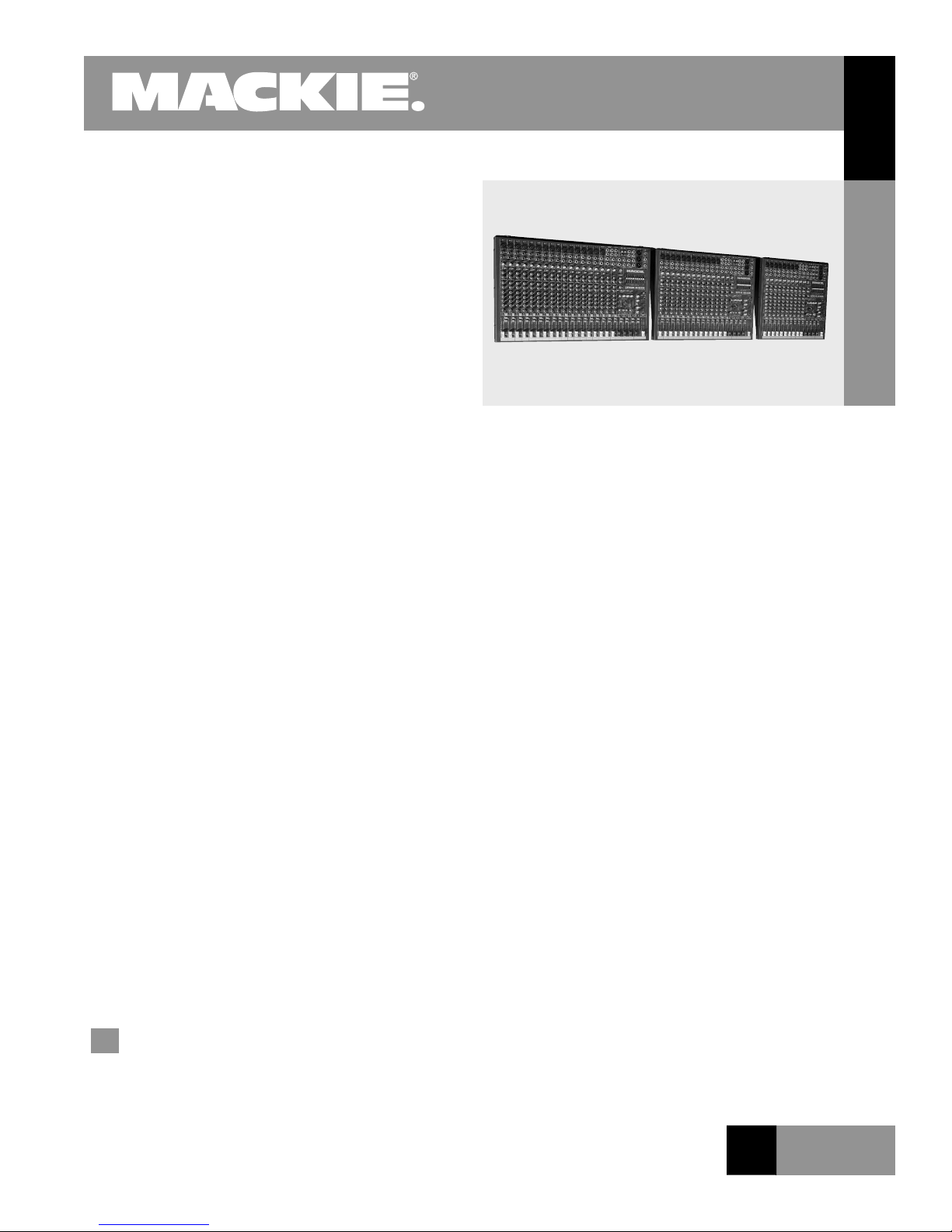
CFX SERIES 12-, 16-, and 20-Channel Mic/Line Mixers
Introduction
The CFX
pact mixers, each having a stereo graphic equalizer and
digital effects built in. The EMAC™ 32-bit digital effects
processor was custom designed by our digital engineers
and rivals the sound of many high-quality
outboard processors.
Like all Mackie mixers, the CFX Series mixers are
designed for rugged, day-in and day-out road use. Their
sturdy-yet-light steel monocoque construction houses
rugged, double-sided SMT-plated berglass circuit
boards, and 60 mm faders with ultra-tight lip seals
for keeping out dust and other contaminants. Impactresistant knobs are mounted so they “ride” just above
the steel chassis––they absorb impact without trouble.
Furthermore, they’re designed to last, thanks to co-molded potentiometers that do not get brittle and crack up.
Metal stand-offs are used at regular intervals to mount
thick berglass circuit boards inside the mixer. These are
extremely exible mixers, not only because of their multiple input/output congurations, but also because of their
4 subgroups, 9-band graphic EQ, and built-in
digital effects.
The CFX•12 has eight mic/line channels and two stereo
line input channels, the CFX•16 has 12 mic/line channels
and two stereo line input channels, and the CFX•20 has
16 mic/line channels and two stereo line input channels. All mic/line channels have unbalanced inserts. Each
channel strip has one external and one internal/external
effects send plus two aux sends, pan, mute, solo (PFL),
bus assigns, and 60 mm log-taper fader. The mic/line
channels also have input trim controls with individual
Zero Level LEDs, 3-band EQ with swept midrange, and
100 Hz low cut lters. Two separate stage monitor mixes
can be created with their own effects levels.
The CFX Series is a true 4-bus mixer, with four sub
bus faders and master ganged Left/Right fader. Outputs
include XLR and TRS balanced/unbalanced main outputs,
a 75 Hz low-pass subwoofer XLR output, extra TRS
(continued on page 3)
™
Series mixers are comprised of three com-
MIXERS
CFX Series
Features
High headroom mic preamps
CFX•12 channels (8 mic/line mono, 2 stereo line)
CFX•16 channels (12 mic/line mono, 2 stereo line)
CFX•20 channels (16 mic/line mono, 2 stereo line)
32-bit EMAC digital effects
External and internal EFX sends
EFX to Monitor control
9-band stereo graphic equalizer
Inserts on all mic channels and main mix
True 4-bus design with direct sub outs and L/R assign
2 Pre/Post aux sends and internal/external FX level sends
3-band EQ with swept mid (100 Hz to 8 kHz) on mic/line
4-band EQ on stereo line channels
Pan, Mute, PFL solo on each channel
100 Hz low-cut lters on all mic/line channels
Subwoofer output from built-in 18 dB/octave,
75 Hz crossover
Break switch mutes all channels
Headphone output with level control
Tape/CD inputs with level control assignable to Main Mix
via Break switch
Logarithmic taper 60 mm faders
48 V phantom power
12 V BNC lamp jack
R E L A T E D P R O D U C T S
SRM350/SRM450 Active Loudspeaker, SR1530 Threeway Active Loudspeaker, SWA 1501 and SWA 1801
Active Subwoofers, M•800, M•1400, M•1400i Power
Ampliers, C200/C300z Passive 2-Way Loudspeakers
Applications
Live sound mixing for churches, clubs, schools, con-
ference centers, tradeshows, presentations
Keyboard, drum machine, and DJ mixing
A/V presentations, multimedia
O F 8 P A G E S
1
Page 2

CFX Series
CFX SERIES 12-, 16-, and
20-Channel Mic/Line Mixers
MIXERS
Specications
Frequency Response:
32 Hz to 20 kHz +0, –1 dB
Distortion:
THD and SMPTE IMD; 20 Hz to 20 kHz
Mic Input to Main Output < 0.05% @ +4 dBu output
Noise:
20 Hz to 20 kHz (150 Ohms source impedance)
Equivalent Input Noise (EIN) –127 dBU
CFX Series
Residual Output Noise Main, Monitor, & Effects outputs
Channel & Master levels off –95 dBU
Common Mode Rejection Ratio (CMRR):
@1 kHz, Trim @ 0 dB 60 dB
Crosstalk:
Adjacent Inputs or Input to Output –90 dB @ 1 kHz
Fader Off –90 dB @ 1 kHz
Mute Switch and Break Switch Mute –80 dB @ 1 kHz
Input Level Trim Control Range:
+6 to –50 dB
Phantom Power:
+48 VDC
Equalization
Low Cut: 100 Hz, –18 dB/octave
Mono Channel EQ:
High +15 dB @ 12 kHz
Mid +15 dB @ 100 Hz to 8 kHz
Low +15 dB @ 80 Hz
Stereo Channel EQ:
High +15 dB @ 12 kHz
High Mid +15 dB @ 100 Hz to 3 kHz
Low Mid +15 dB @ 400 Hz
Low +15 dB @ 80 Hz
Graphic EQ:
(9 bands): +15 dB, Q=1.414 ISO octave centers @ 63 Hz,
125 Hz, 250 Hz, 500 Hz, 1k,
2k, 4k, 8k, 16 kHz
Mixer Rated Output:
Main, Sub, Aux, & EFX +4 dBU
Maximum Rated Output +20 dBU
Maximum Input Levels:
Mic input, trim @ +6 dB +18 dBu
Line input, trim @ –15 dB +38 dBu
Insert Return, Stereo Line Input,
Tape Input, and Effects Return +20 dBu
Maximum Voltage Gain:
Mic Input to
Insert Output 50 dB
Tape Output 66 dB
Sub Output 66 dB
Main Output 76 dB
Aux Send 71 dB
Line Input to
Insert Output 30 dB
Tape Output 46 dB
Sub Output 46 dB
Main Output 56 dB
Aux Send 51 dB
Stereo Line Input to
Tape Output 40 dB
Sub Output 40 dB
Main Output 50 dB
Aux Send 45 dB
Tape Input to
Main Output 30 dB
Effects Return to
Main Output 30 dB
Input Impedance
Mic Input: 3 kΩ, balanced
Line Input: 40 kΩ, balanced
Insert Return, Stereo Line Input,
Tape Input, and Effects Returns: 10 kΩ, unbalanced
Output Impedance
Main Output, Insert Output, Tape Output,
Sub Output, and Effects Sends: 150 Ω
Digital Effects
Resolution:
32-bit EMAC processing, 2-channel
Number of Presets:
16
Parameters:
2 controllable
Channel Level Set LED (Sensitivity):
0 dBu (normal operating level)
VU Meters
Main L/R
12 Segments: Clip, +10, +7, +4, +2, 0, –2, –4, –7,
–10, –20, –30
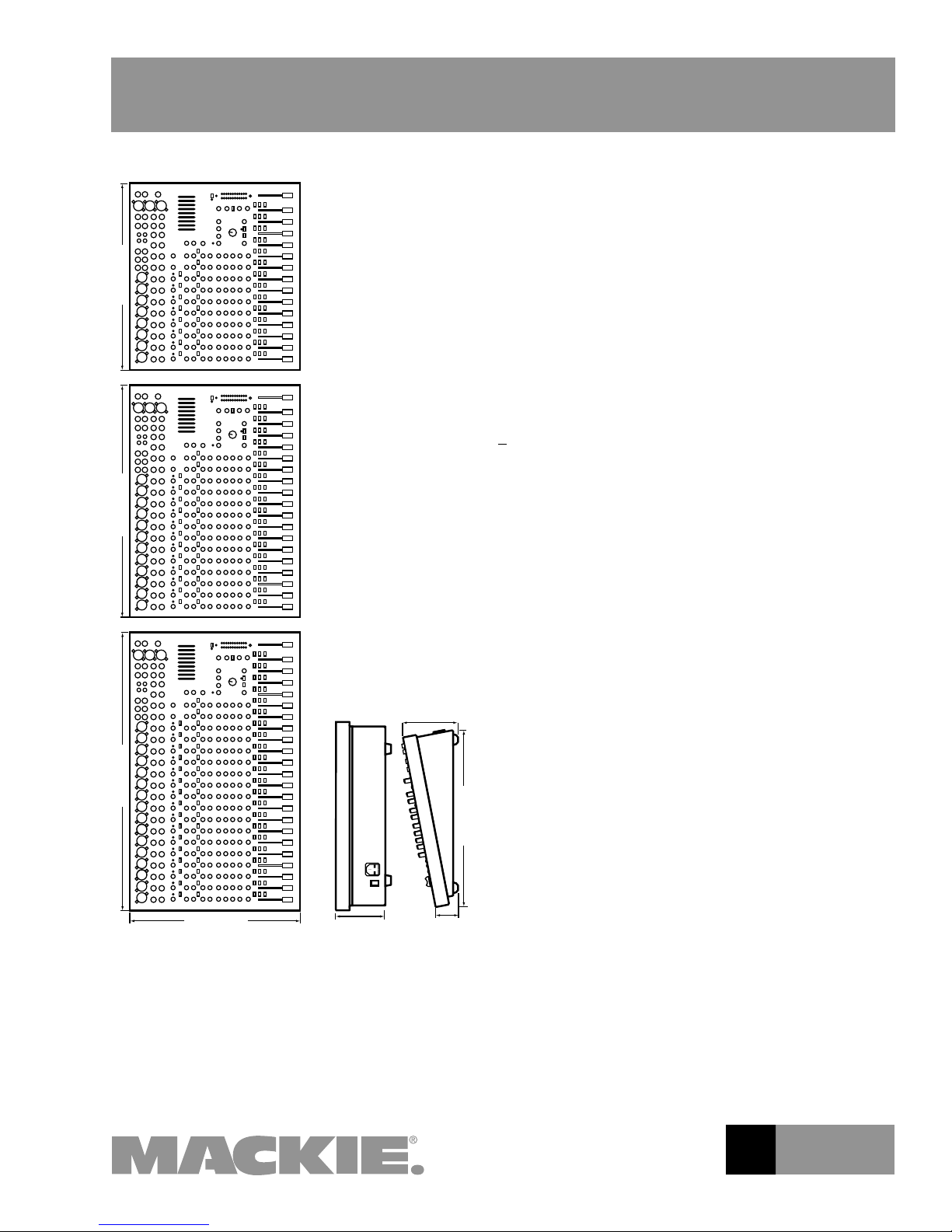
Physical Dimensions:
CFX•12
Height 4.6" (117 mm)
Width 17.2" (437 mm)
Depth 15.7" (399 mm)
Overall Depth 5.0" (127 mm)
Weight 17.8 lbs. (8.1 kg)
CFX•16
Height 4.6" (117 mm)
Width 21.4" (544 mm)
Depth 15.7" (399 mm)
Overall Depth 5.0" (127 mm)
Weight 21.0 lbs. (9.5 kg)
CFX•20
Height 4.6" (117 mm)
Width 25.6" (650 mm)
Depth 15.7" (399 mm)
Overall Depth 5.0" (127 mm)
Weight 24.3 lbs. (11.0 kg)
2
O F 8 P A G E S
Page 3
CFX SERIES 12-, 16-, and
4.6"/ 117mm
15.7"/399mm
5.0"/127mm
2.1"/53mm
16.2"/412mm
17.2"/437mm
21.4"/ 544mm
25.6"/650mm
CFX Series
20-Channel Mic/Line Mixers
CFX Series Dimensions
add effects to stage monitor mixes independently of
the EFX levels added to the main mix. Below the level
controls is the preset selector for picking which effect
you want. The characteristics of these presets can be
changed with the TIME/RATE and DAMPING/DEPTH
knobs. Between these controls are a BYPASS SWITCH
and an EFX WIDE control. Wide adds psychoacoustic
“width” or “depth” to all effects except delay and
phaser.
The Stereo Graphic Equalizer is nine bands with
+15 dB of gain and centers at 63 Hz, 125 Hz, 250 Hz,
500 Hz, 1 kHz, 2 kHz, 4 kHz, 8 kHz, and 16 kHz. This
EQ is exceptionally low-noise, low-distortion, and free
of phase distortion.
Trim Controls have 50 dB of mic gain, +30 dB of
line-level gain, and a full 15 dB of attenuation to
“pad” hot signals. Each channel also includes a Zero
(continued from page 1)
Utility outputs that are independent of the master gain
control, and tape and sub bus outputs.
The EMAC Digital Effects section includes four con-
trols at the top. EFX 2 regulates the signal level being
sent to the EMAC effects processor from an individual
channels strip’s EFX 2 aux send. The overall level is
monitored by the CLIP LED to prevent overload. TO
MAIN MIX controls the amount of effects sent to your
main mix. The two EFFECTS TO MONITOR knobs let you
Level Set LED for easy level setting. All mic channels
have a 100 Hz low cut lter to reduce stage vibration, mic stand rumble, and wind noise. Each channel
includes a Pre-Fader Solo switch.
Channel EQs are as follows: 12 kHz shelving HIGH
frequency EQ, sweepable peaking Midrange EQ
(only on mono input channels), with a 100 Hz to 8
kHz bandwidth. Stereo channels employ a 2-stage
xed-frequency MID EQ, HI-MID is centered at 3 kHz;
LOW-MID is centered at 400 Hz; and a LOW EQ that is
shelved at 80 Hz.
Log-taper 60 mm faders deliver a consistent fade
throughout the fader’s throw. These faders have a
co-polymer membrane that provides a continuously
sealed barrier against dust and liquids without interfering with fader travel. Similarly, the fader’s longwearing contact material (rst designed for use in
exterior automotive sensors) means longer fader life
and improved resistance to the elements.
The CFX Series mixers are designed for continuous,
hassle-free use in any sound reinforcement installation. And they’re packed with useful features and
practical routing capabilities. Simply stated, these
mixers offer more features, more peace of mind, and
more possibilities than any other mixers in their class.
And they're Mackies.
O F 8 P A G E S
3
Page 4

CFX Series
MAIN OUT
LEFT
MAIN OUT
RIGHT
STEREO EFX
RETURN 1 RIGHT
STEREO EFX
RETURN 1 LEFT
SOLO CONTROL
(ACTIVE LOW)
RUDE SOLO
LIGHT
SOLO
OFF
SOLO
ON
UTILITY OUT LEFT
EFX SEND 2
EFX SEND 2
EFX
SELECT
STEREO EFX
RETURN 2
RIGHT
STEREO EFX
RETURN 2 LEFT
EFX TO MAIN MIX
AUX SEND 1
AUX SEND 2
EFX TO AUX 1
EFX TO AUX 2
TO LEFT MAIN
TO
RIGHT MAIN
PFL
SIGNAL
TO PHONES
PFL
UTILITY
LEVEL
PHONES LEVEL
PHONES
UTILITY OUT RIGHT
PFL
SIGNAL
TO LEFT
METER
221074202471020
30
100 Hz
HPF
MID FREQ HI
80 12K
LO
1-2
3-4
AUX 1
AUX 2
EFX 1
EFX 2
PRE-P0ST
PA
N
FADER
TRIM
LINE IN
STEREO
CHANNELS
MIC/LINE IN
MONO CHANNELS
LOW CUT
INSERT
LEVEL
SET
SOLO
3-4
MID HI
80 800 12K
LO
MID
3K
MID HI
80 800 12K
LO
MID
3K
AUX 1
AUX 2
EFX 1
EFX 2
PRE/POST
PA
N
MAIN
TRIM
LEFT
RIGHT
SOLO
1-2
MUTE
EFX RETURN 1
SUBWOOFER
OUT
1
2
3
63 125
250
5001K
2K
4K
8K 16K
TAPE OUT
RIGHT
BREAK
MAIN
LEVEL
MAIN INSERT
LEFT
ASSIGN
RIGHT
ASSIGN
SUB 1 OUT
63 125
250
5001K
2K
4K
8K 16K
TAPE OUT
LEFT
BREAK
TAPE
LEVEL
MAIN
LEVEL
MAIN INSERT
TAPE IN
LEFT
TAPE IN
RIGHT
EFX
2
EFX
1
SOL
O
SOL
O
CONTR
OL
A
UX
2
A
UX
1
SUB
1
SUB
2
SUB
3
SUB
4
LEFT
MAIN
RIGHT
MAIN
EFX SEND 1
AUX SEND 2
AUX SEND 1
EFX SEND 1
FROM EFX
TO
MAIN MIX
75 Hz
LPF
MUTE
PHANTOM POWER
+48 VDC
MACKIE DESIGNS
CFX SERIES
BLOCK DIAGRAM
(#62399CJM/DF)
+5
VDC
2
3
1
1
2
3
1
2
3
DAMPING/DEPTH
TIME/RATE
EFX WIDE
EFX BYPASS
EFX BYPASS
EFX
FOOT
SWITCH
+5
VDC
EMAC
DSP
EFX LEVEL SET
L
R
SOLO CONTROL
(ACTIVE LOW)
SOLO
OFF
SOLO
ON
SUB 2 OUT
LEFT
ASSIGN
RIGHT
ASSIGN
LEFT
ASSIGN
RIGHT
ASSIGN
LEFT
ASSIGN
RIGHT
ASSIGN
SUB 4 OUT
SUB 3 OUT
CFX Series Block Diagram
CFX SERIES 12-, 16-, and
20-Channel Mic/Line Mixers
O F 8 P A G E S
4
Page 5

CFX Series
CLIP
WIDE BYPASS
100
100
REVERBS
DELAYS
CHORUS/FLANGE/PHASER
DAMPING
DEPTH
TIME
RATE
NORMAL
NORMAL
EFX
SM. ROOM
MD. PLATE
LG. PLATE
LG. HALL
GATED
REVERSE
CATHEDRAL
MD. HALL
SPRING
PHASER
DELAY 4
CHORUS
DELAY 3
DELAY 1
FLANGE
DELAY 2
1
3-4
1-2
MUTE
CLIP
0d
B=0dBu
LEFT RIGHT
MID
400Hz
MID
400Hz
U
+1
5
OO
U
+1
5
OO
U
+1
5
OO
U
+1
5
OO
1
2
600
1.5k150
8k100
12k
HI
MID
FREQ
80Hz
LOW
EQ
U
+1
5
-1
5
U
+1
5
-1
5
U
+1
5
-15
600
1.5k150
8k100
12
k
HI
MID
FREQ
80Hz
LOW
EQ
U
+1
5
-1
5
U
+15
-1
5
U
+1
5
-15
600
1.5k150
8k100
12
k
HI
MID
FREQ
80Hz
LOW
EQ
U
+1
5
-1
5
U
+1
5
-1
5
U
+1
5
-15
600
1.5k150
8k100
12
k
HI
MID
FREQ
80Hz
LOW
EQ
U
+1
5
-1
5
U
+1
5
-1
5
U
+1
5
-15
600
1.5k150
8k100
12
k
HI
MID
FREQ
80Hz
LOW
EQ
U
+1
5
-1
5
U
+1
5
-1
5
U
+1
5
-15
600
1.5k150
8k100
12
k
HI
MID
FREQ
80Hz
LOW
EQ
U
+1
5
-1
5
U
+1
5
-1
5
U
+1
5
-15
600
1.5k150
8k100
12
k
HI
MID
FREQ
80Hz
LOW
EQ
U
+1
5
-1
5
U
+1
5
-1
5
U
+1
5
-15
600
1.5k150
8k100
12
k
HI
MID
FREQ
80Hz
LOW
EQ
U
+1
5
-1
5
U
+1
5
-1
5
U
+1
5
-1
5
ASSIGN
SUB
1
MIC
1
BAL/UNBAL
LINE IN
INSERT
BAL/UNBAL
LINE IN
INSERT
BAL/UNBAL
LINE IN
INSERT
BAL/UNBAL
LINE IN
INSERT
BAL/UNBAL
LINE IN
INSERT
BAL/UNBAL
LINE IN
INSERT
BAL/UNBAL
LINE IN
INSERT
BAL/UNBAL
LINE IN
INSERT
MIC
2
MIC
3
MIC
4
MIC
5
MIC
6
MIC
7
MIC
8
ZERO
LEVE
L
SE
T
TAPE LEVEL
OO
MAX
PHONES LEVEL
UTILITY OUT LEVEL
1
(EXT)
48v
L R
PAN
L R
PAN
L R
PAN
L R
PAN
L R
PAN
L R
PAN
L R
PAN
L R
PAN
L R
PAN
L R
PAN
RIGHT
LEF
T
RIGHT
LEF
T
RIGHT
LEF
T
RIGHT
LEF
T
3-4
1-2
MUTE
3-4
1-2
MUTE
3-4
1-2
MUTE
3-4
1-2
MUTE
3-4
1-2
MUTE
3-4
1-2
MUTE
3-4
1-2
MUTE
3-4
1-2
MUTE
3-4
1-2
MUTE
dB
30
20
10
OO
40
50
5
5
U
60
10
SOLO
PFL
dB
30
20
10
OO
40
50
5
5
U
60
10
SOLO
PFL
dB
30
20
10
OO
40
50
5
5
U
60
10
SOLO
PFL
dB
30
20
10
OO
40
50
5
5
U
60
10
SOLO
PFL
dB
30
20
10
OO
40
50
5
5
U
60
10
SOLO
PFL
dB
30
20
10
OO
40
50
5
5
U
60
10
SOLO
PFL
dB
30
20
10
OO
40
50
5
5
U
60
10
SOLO
PFL
dB
30
20
10
OO
40
50
5
5
U
60
10
SOLO
PFL
dB
30
20
10
OO
40
50
5
5
U
60
10
SOLO
PFL
dB
30
20
10
OO
40
50
5
5
U
60
10
SOLO
PFL
dB
30
20
10
OO
40
50
5
5
U
60
10
dB
30
20
10
OO
40
50
5
5
U
60
10
dB
30
20
10
OO
40
50
5
5
U
60
10
dB
30
20
10
OO
40
50
5
5
U
60
10
dB
30
20
10
OO
40
50
5
5
U
60
10
15
15
5
10
0
5
10
15
15
5
10
0
5
10
1
EFX
2
(INT)
EF
X
1
(EXT)
POWER STATUS
RUDE SOLO
BREAK SWITCH
(MUTES ALL CHANNELS)
PRE FADER
AUX
U
+1
5
OO
U
+1
5
OO
U
+1
5
OO
U
+1
5
OO
1
2
EFX
2
(INT)
EF
X
1
(EXT)
PRE FADER
AUX
U
+1
5
OO
U
+1
5
OO
U
+1
5
OO
U
+1
5
OO
1
2
EFX
2
(INT)
EF
X
1
(EXT)
PRE FADER
AUX
U
+1
5
OO
U
+1
5
OO
U
+1
5
OO
U
+1
5
OO
1
2
EFX
2
(INT)
EF
X
1
(EXT)
PRE FADER
AUX
U
+1
5
OO
U
+1
5
OO
U
+1
5
OO
U
+1
5
OO
1
2
EFX
2
(INT)
EF
X
1
(EXT)
PRE FADER
AUX
U
+1
5
OO
U
+1
5
OO
U
+1
5
OO
U
+1
5
OO
1
2
EFX
2
(INT)
EF
X
1
(EXT)
PRE FADER
AUX
U
+1
5
OO
U
+1
5
OO
U
+1
5
OO
U
+1
5
OO
1
2
EFX
2
(INT)
EF
X
1
(EXT)
PRE FADER
AUX
U
+1
5
OO
U
+1
5
OO
U
+1
5
OO
U
+1
5
OO
1
2
EFX
2
(INT)
EF
X
1
(EXT)
PRE FADER
AUX
U
+1
5
OO
U
+1
5
OO
U
+1
5
OO
U
+1
5
OO
1
2
EFX
2
(INT)
EFX
1
(EXT)
PRE FADER
AUX
U
+1
5
OO
U
+1
5
OO
U
+1
5
OO
U
+1
5
OO
1
2
EFX
2
(INT)
EF
X
1
(EXT)
PRE FADER
AUX
2
ASSIGN
2
3
ASSIGN
3
4
ASSIGN
4
5
ASSIGN
5
6
ASSIGN
6
7
ASSIGN
7
8
ASSIGN
8
9-10
ASSIGN
9
10
11-12
U
+15
OO
U
+15
OO
U
+15
OO
U
+15
OO
U
+20
OO
U
+20
OO
U
+10
OO
U
+15
OO
U
+15
OO
U
+15
OO
1
2
ASSIGN ASSIGN
SUB
2
ASSIGN
SUB
3
ASSIGN
SUB
4
ASSIGN
11
12
AUX
EFX
MASTER SEND
U
TRIM
+20
-20
U
TRIM
+20
-20
LOW LOW
22
10
7
4
2
0
2
4
7
10
20
30
STEREO
MAIN MIX
TRIM
LOW CUT
100 Hz
ZERO
LEVEL
M
I
C
G
A
I
N
6
+50
U
-15dB
+30d
B
TRIM
LOW CUT
100 Hz
ZERO
LEVEL
M
I
C
G
A
I
N
6
+50
U
-15dB
+30d
B
TRIM
LOW CUT
100 Hz
ZERO
LEVEL
M
I
C
G
A
I
N
6
+50
U
-15dB
+30d
B
TRIM
LOW CUT
100 Hz
ZERO
LEVEL
M
I
C
G
A
I
N
6
+50
U
-15dB
+30d
B
TRIM
LOW CUT
100 Hz
ZERO
LEVEL
M
I
C
G
A
I
N
6
+50
U
-15dB
+30d
B
TRIM
LOW CUT
100 Hz
ZERO
LEVEL
M
I
C
G
A
I
N
6
+50
U
-15dB
+30d
B
TRIM
LOW CUT
100 Hz
ZERO
LEVEL
M
I
C
G
A
I
N
6
+50
U
-15dB
+30d
B
TRIM
LOW CUT
100 Hz
ZERO
LEVEL
M
I
C
G
A
I
N
6
+50
U
-15dB
+30d
B
PHONES
FOOT
SWITCH
EFX
LAMP
12V 0.5A
MAIN OUT
L
R
11
LEFT
AUX SENDUTILITY OUT
SUB OUT
TAPE
INPUT
TAPE
OU
TPUT
L L
R
1
2
1
2
L
L R
R
L
R
EFX SEND
STEREO EFX
RETURN
MAIN INSERT
(MONO) (MONO)
L
R
S
75Hz
SUB OUT
R
1
2
1
2
3
4
MAIN OUT
9
LEFT
RIGHT
10
RIGHT
12
EFX 1 RETURN
EFX 2 (INT) RETURN MASTERS
EFX
2
SEND
TO MAIN MIX
EFFECTS TO MONITOR
AUX
1 AUX 2
PHANTOM POWER
CFX 12 MIXER
STEREO GRAPHIC EQ
1K50025063 125 16K2K 4K 8K
12 CHANNEL COMPACT INTEGRATED LIVE SOUND MIXER
CUSTOM 32-BIT PRECISION
DIGITAL STEREO EFFECTS PROCESSOR
12k
HI
HI
MID
3k
80Hz
LOW
EQ
U
+1
5
-1
5
U
+1
5
-1
5
U
+1
5
-1
5
U
+1
5
-1
5
12
k
HI
HI
MID
3k
80Hz
LOW
EQ
U
+1
5
-1
5
U
+1
5
-1
5
U
+1
5
-1
5
U
+1
5
-1
5
CFX SERIES 12-, 16-, and
20-Channel Mic/Line Mixers
5
O F 8 P A G E S
Page 6

CFX Series
POWER
ON
120V, 60Hz, .85A
FUSE 1.25A, 250V SLOW
CFX12 MIXER
12 CHANNEL COMPACT INTEGRATED LIVE SOUND MIXER
SERIAL NUMBER
MANUFACTURING DATE
RISK OF ELECTRIC SHOCK
DO NOT OPEN
REPLACE WITH THE SAME TYPE FUSE AND RATING.
DISCONNECT SUPPLY CORD BEFORE CHANGING FUSE
UTILISE UN FUSIBLE DE RECHANGE DE MÊME TYPE.
DEBRANCHER AVANT DE REMPLACER LE FUSIBLE
WARNING:
TO REDUCE THE RISK OF FIRE OR ELECTRIC SHOCK, DO NOT
EXPOSE THIS EQUIPMENT TO RAIN OR MOISTURE. DO NOT REMOVE COVER.
NO USER SERVICEABLE PARTS INSIDE. REFER SERVICING TO QUALIFIED PERSONNEL.
CA UT IO N
AVIS:
RISQUE DE CHOC ELECTRIQUE — NE PAS OUVRIR
CONCEIVED, DESIGNED, AND MANUFACTURED BY MACKIE DESIGNS INC • WOODINVILLE • WA • USA • MADE IN USA • FABRIQUE AU USA • COPYRIGHT ©1998 • THE
FOLLOWING ARE TRADEMARKS OR REGISTERED TRADEMARKS OF MACKIE DESIGNS INC.: "MACKIE", "EMAC", AND THE "RUNNING MAN" FIGURE • PATENT PENDIN
G
TIP OUT TO EFFECTS DEVICE
RING RETURN FROM EFFECTS
STEREO
PLUG
FOR USE AS AN EFFECTS LOOP
(TIP = SEND, RING = RETURN
)
DIRECT OUT WITH SIGNAL
INTER
RUPTION TO MASTER
OPTIONAL USES FOR INSERTS
INSERT ALL THE WAY IN TO
THE "SECOND CLICK"
MONO PLUG
CFX SERIES 12-Channel Rear Panel
CFX SERIES 12-, 16-, and
20-Channel Mic/Line Mixers
6
O F 8 P A G E S
Page 7

CFX Series
CFX SERIES 12-, 16-, and
20-Channel Mic/Line Mixers
Architects’ and Engineers’ Specications
1. GENERAL CONFIGURATION. The CFX•12 mixer shall
accommodate 8 microphone signals: mono channels 1-8;
12 line signals: mono channels 1-8, and stereo channels
9-12. The CFX•16 mixer shall accommodate 12 microphone signals: mono channels 1-12; 16 line signals:
mono channels 1-12, and stereo channels 13-16. The
CFX•20 mixer shall accommodate 16 microphone signals:
mono channels 1-16; 20 line signals: mono channels
1-16, and stereo channels 17-20. The CFX Series mixers
shall have 2 stereo pairs of Aux Return inputs, a Send/
Return channel Insert for each mic/line channel, 2 stereo
pairs of Main Mix outputs, 1 stereo pair of RCA-type Tape
Inputs, 1 stereo pair of RCA-type Tape Outputs, 1 stereo
pair of Utility outputs, 2 Aux Send outputs, 4 Submaster
outputs, and 1 stereo headphone output. The mixers shall
be tted with 1 rocker-type Power switch, one 3-pin power
receptacle, 1 BNC socket providing 12 VDC for tting an
external lamp (not included), 1 EFX Bypass footswitch
jack, and shall be entirely self contained.
2. MIXER INPUTS.
MONO CHANNELS: Each monaural input channel shall
have an electronically balanced microphone-level input
using XLR-3-F-type connectors, accepting nominal microphone levels between –50 dBu and +4 dBu via rotary
Trim controls. 48 V phantom power shall be available via
a globally-controlled switch. Each monaural input channel shall also have an electronically balanced line level
input, accepting a nominal line-level of between –10 dBV
and +4 dBu, using 1/4" TRS phone jacks. In addition,
each monaural input channel shall include an unbalanced
insert connection using 1/4" TRS phone jacks (tip=send,
ring=return, sleeve=ground), delivering and accepting
nominal levels from –10 dBV to +4 dBu.
Each stereo input channel shall have left and right electronically balanced line-level inputs, accepting nominal
levels from –10 dBV to +4 dBu. These jacks shall be tted
with internal switching contacts to accommodate monaural conguration.
OTHER INPUTS: Each mixer shall include 4 bal/unbal
Aux Return inputs, forming two stereo pairs, using 1/4"
TRS phone jacks and accepting nominal levels from –10
dBV to +4 dBu. The mixer shall include 1 stereo pair of
Tape In jacks, using unbalanced RCA-type phono jacks,
accepting nominal levels from –10 dBV to +4 dBu.
3. MIXER OUTPUTS.
MAIN OUTPUTS: The mixer’s Main Output stereo pairs
shall be tted in three ways: Using XLR-3-M-type connectors with a maximum output of +20 dBu; using bal/unbal
1/4" TRS phone jacks, delivering nominal levels from –10
dBV to +4 dBu; and using unbalanced RCA-type phono
jacks (labeled TAPE OUT) delivering nominal levels from
–10 dBV to +4 dBu.
OTHER OUTPUTS: Each mixer shall include 1 Subwoofer
Output using an XLR-3-M-type connector that includes
a built-in 18 dB/octave 75 Hz crossover. The mixer shall
include 4 Submaster outputs, using bal/unbal 1/4" TRS
phone jacks, delivering nominal levels from –10 dBV to +4
dBu; 1 stereo pair of Utility outputs, using bal/unbal 1/4"
TRS phone jacks, delivering nominal levels from –10 dBV
to +4 dBu; 2 Aux Send outputs using bal/unbal 1/4" TRS
phone jacks, delivering nominal levels from –10 dBV to +4
dBu; 2 EFX Send outputs using bal/unbal 1/4" TRS phone
jacks, delivering nominal levels from –10 dBV to +4 dBu;
and 1 stereo Headphones output, using an unbalanced 1/
4" TRS phone jack (tip=left, ring=right, sleeve=ground).
4. MIXER INPUT SECTION. Each monaural channel shall
include 1 rotary Trim control, 1 Zero Level LED that is triggered to glow when an audio signal at or above 0 dBu is
passed through the channel, Low-Cut lter (HPF) providing
an 18 dB per octave curve at 100 Hz, 2 rotary Aux Send
controls providing up to 15 dB above unity gain, 1 PreFader switch assignable to Aux Sends 1 & 2, and 2 EFX
Send controls, providing up to 15 dB above unity gain.
Each monaural channel shall include 4 rotary equalization
(EQ) controls: +15 dB xed 12 kHz shelving gain, +15 dB
midrange peaking gain, 100 Hz-8 kHz midrange frequency,
and +15 dB xed 80 Hz shelving. Each monaural channel
shall also include 1 rotary Pan control, 4 dB attenuation
panned center, and 1 Mute switch. Each monaural channel
shall also include 2 output Assign switches delivering the
channel’s signal relative to its Pan setting to Submasters
1-2 and Submasters 3-4, 1 channel Fader providing up to
10 dB above unity gain, and 1 Pre-Fader (PFL) Solo switch.
5. MIXER OUTPUT SECTION. The mixer shall have 1 Main
Mix stereo fader providing up to 10 dB gain, 4 Submaster
mono faders, (each providing up to 10 dB gain), independent left and right Assign to Main Mix switches for each
submaster, 1 Utility Out level rotary stereo control, providing up to 10 dB gain, and 1 Phones level rotary stereo control providing up to 10 dB gain. The mixer shall also have 1
Break switch that mutes all input channels to Main Mix, 1
rotary stereo Tape In level control providing up to 20 dB of
gain, 1 rotary stereo EFX Return level control providing up
to 20 dB of gain, and 1 Phantom Power switch providing 48
V of phantom power to each mic input channel. The mixer
shall also have 2 rotary Aux Send Master controls for Aux
Sends 1 and 2 providing up to 15 dB above unity gain, and
1 EFX Send Master control for EFX Send 1 providing up to
15 dB above unity gain. The mixer shall also have a 9-band
graphic equalizer providing +15 dB of gain at 63 Hz, 125
Hz, 250 Hz, 500 Hz, 1 kHz, 2 kHz, 4 kHz, 8 kHz, 16 kHz;
a blinking master Solo LED; a Power indicator LED; and a
Phantom Power indicator LED.
MIXERS
CFX Series
O F 8 P A G E S
7
Page 8

CFX Series
MIXERS
6. EMAC EFFECTS PROCESSOR. The 32-bit EMAC Digital
Stereo Effects Processor shall include 16 preset digital
effects algorithms selectable by a detented knob. Effects
shall include 9 Reverb types: Spring, Small Room, Medium
Plate, Large Plate, Medium Hall, Large Hall, Cathedral,
Gated, and Reverse. Effects shall also include 4 Delay
Types: Delay 1 providing one repeat, Delay 2 providing
two repeats, Delay 3 providing three repeats, and Delay 4
providing four repeats. Effects shall also include 1 Chorus,
1 Flange, and 1 Phaser. Two rotary parameter knobs shall
CFX SERIES
provide control over Time/Rate and Damping/Depth. The
EMAC shall include 1 EFX WIDE button providing more
width or depth to the effect, and 1 Bypass button that
mutes the effect’s output signal. The EMAC shall also
include 1 EFX 2 Send rotary knob providing up to 15 dB of
gain above unity, and control of the dry signal being sent
to the input of the EMAC, and 1 To Main Mix rotary knob
providing up to 15 dB of gain above unity and control over
signals sent from Stereo EFX Return 2. The EMAC shall also
include 2 Effects To Monitor rotary knobs labeled Aux 1 &
Aux 2 providing up to 15 dB of gain above unity and control over signals sent from Stereo EFX Return 2 and being
sent to Aux Sends 1 & 2 and a Clip LED that indicates
when the EMAC is 6 dB below clipping.
7. METERING. The mixer shall include 1 stereo 12-segment LED meter with points at –30, –20, –10, –7, –4, –2,
0, +2, +4, +7, +10, and +22 dB. The source signals for the
meters shall be the same signals selected in the Left/Right
Sub Assign, and a solo condition shall replace the Sub
Assign selection with the soloed channel(s). The meters
shall be calibrated so that a 0 dBu signal at the Phones
output shall be indicated as 0 dB on the meters.
CFX SERIES 12-, 16-, and
20-Channel Mic/Line Mixers
8. PHYSICAL CONFIGURATION. The mixer shall be made
of steel and aluminum, painted dark gray and black with
light gray graphics. The CFX12 shall weigh 17 lbs, 8 oz.
(8.1 kg); the CFX16 shall weigh 21 lbs, 0 oz. (9.5 kg); and
the CFX20 shall weigh 24 lbs, 3 oz. (11.0 kg). Optional
rackmount brackets shall allow the CFX12 to be mounted
in a rack system with the chassis surface ush with the
rack rail. The CFX16 and CFX20 are not rackmountable.
Dimensions of the CFX12 shall be 17.2" (437 mm) in
width, 15.7" (399 mm) in depth, and 5.0" (127 mm) in
height. Dimensions of the CFX16 shall be 21.4" (544 mm)
in width, 15.7" (399 mm) in depth, and 5.0" (127 mm) in
height. Dimensions of the CFX20 shall be 25.6" (650 mm)
in width, 15.7" (399 mm) in depth, and 5.0" (127 mm) in
height.
9. SPECIFICATIONS. In addition to specications already
cited, the mixers shall meet or exceed the following specications. Frequency response, microphone input to any
output (Trim at 0 dB), 32 Hz to 20 kHz, +0 dB/–1 dB;
Total Harmonic Distortion (THD), Mic Input to Main Output:
<0.05%@ +4 dBu output; Equivalent Input Noise (EIN),
–127 dBu; Common Mode Rejection Ration (CMRR), 60
dB at 1 kHz, Trim at 0 dB; Residual Output Noise, Main,
Monitor, and Effects outputs, Channel and Master levels
off, –95 dBu; Input impedance, microphone inputs, 3 kΩ;
Line input, 40 kΩ; Insert Return, Stereo Line Input, Tape
Input, and Effects Returns, 10 kΩ; and all outputs, 120 Ω.
10. DESIGNATION. The mixers shall be Mackie CFX12,
CFX16, and CFX20.
www.mackie.com
16220 Wood-Red Road NE, Woodinville, WA 98072 USA
800.898.3211, fax 425.487.4337, sales@mackie.com
UK +44.1268.570.808, fax +44.1268.570.809, uk@mackie.com
Electronic les for this product available at:
www.mackie.com
This Specication Sheet CFXSeries_SS.PDF
Owner/Operator’s Manual CFXSeries_OM.PDF
LOUD Technologies continually engages in research related to product improvement. New material,
production methods, and design renements are introduced into existing products without notice as
a routine expression of that philosophy. For this reason, any current LOUD Technologies product may
differ in some respect from its published description, but will always equal or exceed the original
design specications unless otherwise stated. ©1999–2004 LOUD Technologies Inc. All rights
reserved. Mackie and the “Running Man” gure are registered trademarks of LOUD Technologies Inc.
Part No. 091-218-00 Rev B 09/04
O F 8 P A G E S
8
 Loading...