

Mackie Carrier-grade cc3300 Quick Start Manual
Safety First!
Before connecting and using the
equipment, please read this Quick-Start
Guide carefully and keep it for future
reference.
WARNING! This equipment has been designed
to be installed by qualified professionals
only! There are many factors to be considered
when installing professional sound
reinforcement sy stems, including mechanical
and electrical considerations, as well as
acoustic coverage and performance. Mackie
Industrial strongly recommends that this
equipment be installed only by a professional
sound installer or contractor .
1. Read Instructions—All the safety and
operation instructions should be read
before this Mackie Industrial product is
operated.
2. Water and Moisture—This Mackie Industrial
product should not be used near water –
for example, near a bathtub, washbowl,
sink, in a damp cellar, near a swimming
pool, etc.
3. Foreign bodies and liquids—Be careful not
to allow any foreign bodies or liquids to get
into this Mackie Industrial product.
4. Technical service—The user should never
attempt to make any repairs on this Mackie
Industrial product unless otherwise
indicated in the instruction manual. All
repairs should be made by a qualified
service technician.
5. Installation—Do not install this Mackie
Industrial product in any w ay that is not
indicated in the instruction manual.
6. Respect the safety standards—The entire
sound system must be created in
compliance with the current standards and
laws regarding electrical systems.
Part No. 910-003-20 Rev. C 05/01
© 2001 Mackie Industrial. All Rights Reserved. Printed in Italy.
www.mackieindustrial.com
16220 Wood-Red Road NE Woodinville, WA 98072
TEL +888.337.7404, FAX +425.487.4337 , industrial@mackie.com
UK +44.1268.571.212, FAX +44.1268.570.809 +info@rcf-uk.com
ITALY +39.0522.354.111, FAX +39.0522.926.208 +industrial@rcf.it
FRANCE +33.3.8546.9160, FAX +33.3.8546.9161 +rcf.commercial@wanadoo.fr
GERMANY +49.2572.96042.0, FAX +49.2572.96042.10 +industrial@mackie.de
PATX60
70V/100V Transformer Panel
Quick-Start Guide
The PATX60 is a 70V/100V transformer panel that
replaces the connector panel on the Vision Series
PACX81, PA261, and PA281. It has a 60 watt, 70 Volt
transformer with a terminal strip for external
connections to a 70V or 100V constant-voltage
amplifier.
SERIAL NUMBER
MANUFACTURING DATE
CAUTION:
SUSPENDING THIS SYSTEM SHOULD BE DONE BY QUALIFIED
TECHNICIANS FOLLOWING APPROPRIATE SAFETY STANDARDS
CONCEIVED, DESIGNED, AND MANUFACTURED BY MACKIE
INDUSTRIAL • MADE IN ITALY • COPYRIGHT ©2000 • THE FOLLOWING
ARE TRADEMARKS/REGISTERED TRADEMARKS OF MACKIE DESIGN INC.:
"MACKIE", "MACKIE INDUSTRIAL", & THE "RUNNING MAN" FIGURE
70V
COM
NC
60W
30W
COM
60W
30W
15W
100V
70V
100V
PATX 60
VISION
SERIES
SERIAL NUMBER
MANUFACTURING DATE
CAUTION:
SUSPENDING THIS SYSTEM SHOULD BE DONE BY QUALIFIED
TECHNICIANS FOLLOWING APPROPRIATE SAFETY STANDARDS
CONCEIVED, DESIGNED, AND MANUFACTURED BY MACKIE
INDUSTRIAL • MADE IN ITALY • COPYRIGHT ©2000 • THE FOLLOWING
ARE TRADEMARKS/REGISTERED TRADEMARKS OF MACKIE DESIGN INC.:
"MACKIE", "MACKIE INDUSTRIAL", & THE "RUNNING MAN" FIGURE
70V
COM
NC60W
30W
COM
60W
30W
15W
100V
70V
100V
PATX 60
VISION
SERIES
70V CONSTANT-VOLTAGE DISTRIBUTION SYSTEM
+
–
70V CONSTANT-VOLTAGE
POWER AMPLIFIER
SERIAL NUMBER
MANUFACTURING DATE
CAUTION:
SUSPENDING THIS SYSTEM SHOULD BE DONE BY QUALIFIED
TECHNICIANS FOLLOWING APPROPRIATE SAFETY STANDARDS
CONCEIVED, DESIGNED, AND MANUFACTURED BY MACKIE
INDUSTRIAL • MADE IN ITALY • COPYRIGHT ©2000 • THE FOLLOWING
ARE TRADEMARKS/REGISTERED TRADEMARKS OF MACKIE DESIGN INC.:
"MACKIE", "MACKIE INDUSTRIAL", & THE "RUNNING MAN" FIGURE
70V
COM
NC60W
30W
COM
60W
30W
15W
100V
70V
100V
PATX 60
VISION
SERIES
70V LINE
Strip the speaker wiring back about 1/2", loosen the
screw enough to loop the wire around the shaft of the
screw (clockwise), and tighten down the screw with a
slot-head screwdriver.
Note: Make sure the taps on the speakers add up to
no more than the rated power for the amplifier being
used.
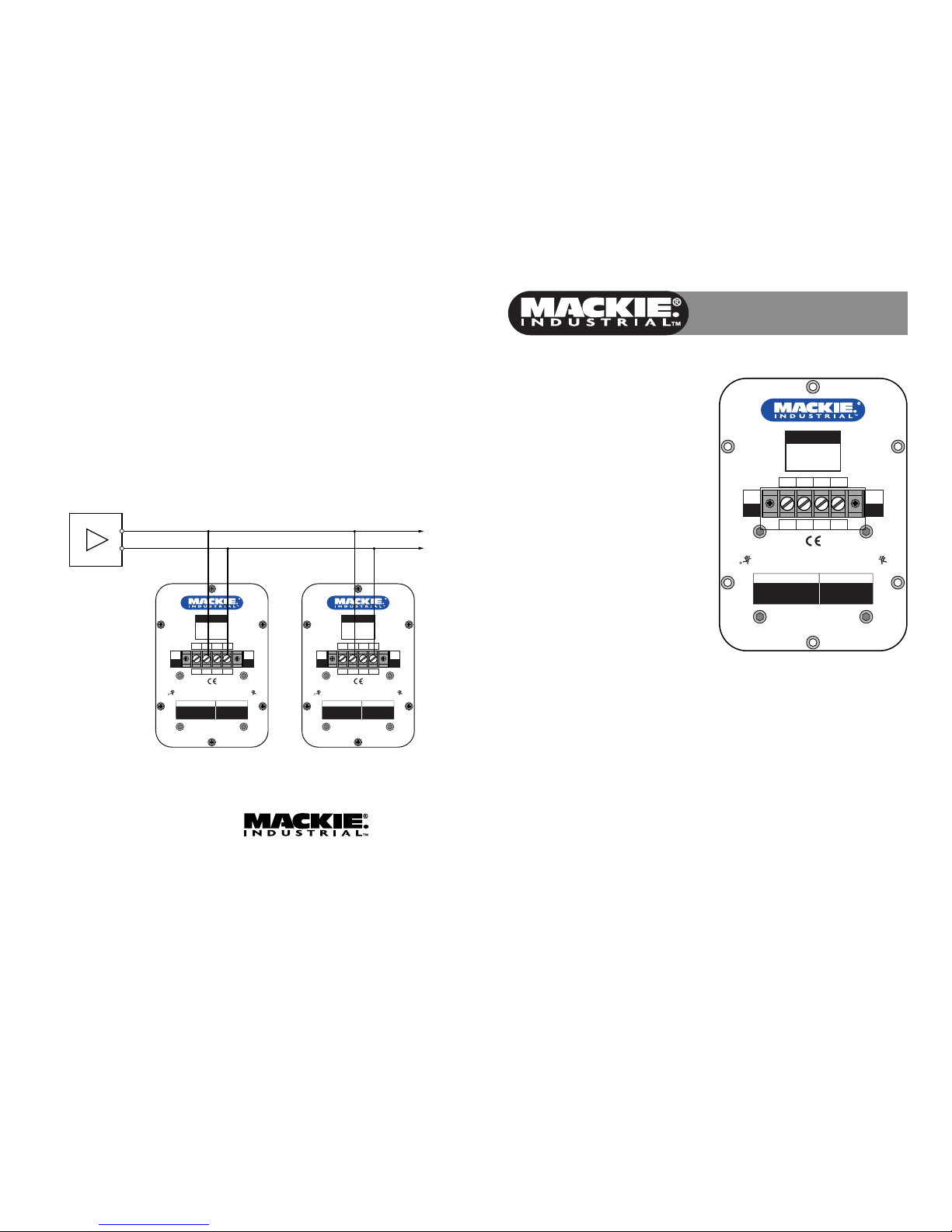
Connecting the PATX60
to a Constant-Voltage
Distribution System
In a constant-voltage distribution system, all the
speakers are connected in parallel. This makes it
easy to add or remove speakers from the system
without having to recalculate the impedance of the
load on the amplifier.
Simply add the taps on the speakers connected to
the system and make sure the total power indicated
by the taps does not exceed the rated power of the
amplifier.
SERIAL NUMBER
MANUFACTURING DATE
CAUTION:
SUSPENDING THIS SYSTEM SHOULD BE DONE BY QUALIFIED
TECHNICIANS FOLLOWING APPROPRIATE SAFETY STANDARDS
CONCEIVED, DESIGNED, AND MANUFACTURED BY MACKIE
INDUSTRIAL • MADE IN ITALY • COPYRIGHT ©2000 • THE FOLLOWING
ARE TRADEMARKS/REGISTERED TRADEMARKS OF MACKIE DESIGN INC.:
"MACKIE", "MACKIE INDUSTRIAL", & THE "RUNNING MAN" FIGURE
70V
COM
NC
60W
30W
COM
60W
30W
15W
100V
70V
100V
PATX 60
VISION
SERIES
Front Panel Features
70V Connections
When using the PATX60 with a 70V distribution
system, calculate the power usage with the top
numbers for the taps (15W, 30W, 60W).
100V Connections
When using the PATX60 with a 100V distribution
system, calculate the power usage with the
bottom numbers for the taps (30W, 60W).
WARNING: DO NOT USE THE TAP LABELED
NC NEXT TO THE COM TERMINAL IN A 100V
SYSTEM.
Security Cover
After connecting the speaker wiring to the screw
terminals, install the security cover to insulate the
connections.
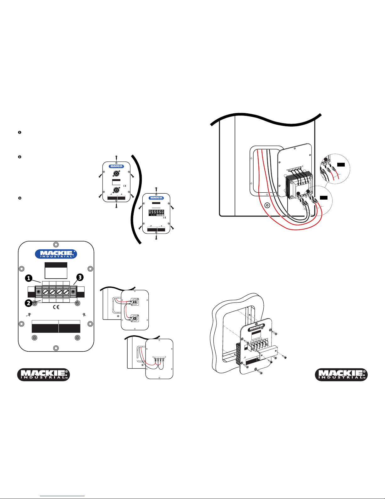
Installing the PATX60
1. Remove the six screws securing the connector
plate to the back of the PACX81, PA261, or
PA281 with a #2 Phillips screwdriver.
IN-OUT
IN-OUT
+1/–1FULL RANGE 200W-4
SERIAL NUMBER
MANUFACTURING DATE
CAUTION:
SUSPENDING THIS SYSTEM SHOULD
BE DONE BY QUALIFIED
TECHNICIANS FOLLOWING
APPROPRIATE SAFETY STANDARDS
CONCEIVED, DESIGNED, AND
MANUFACTURED BY MACKIE
INDUSTRIAL • MADE IN ITALY •
COPYRIGHT ©1999 • THE FOLLOWING
ARE TRADEMARKS/REGISTERED
TRADEMARKS OF MACKIE DESIGN INC.:
"MACKIE", "MACKIE INDUSTRIAL",
& THE "RUNNING MAN" FIGURE
PA 261
VISION
SERIES
FULL RANGE 200W-4
SERIAL NUMBER
MANUFACTURING DATE
CAUTION:
SUSPENDING THIS SYSTEM SHOULD
BE DONE BY QUALIFIED
TECHNICIANS FOLLOWING
APPROPRIATE SAFETY STANDARDS
CONCEIVED, DESIGNED, AND
MANUFACTURED BY MACKIE
INDUSTRIAL • MADE IN ITALY •
COPYRIGHT ©2000 • THE FOLLOWING
ARE TRADEMARKS/REGISTERED
TRADEMARKS OF MACKIE DESIGN INC.:
"MACKIE", "MACKIE INDUSTRIAL",
& THE "RUNNING MAN" FIGURE
PA 261
VISION
SERIES
OUT
IN
2. Remove the connector panel, being careful not
to damage the gasket surrounding the opening
in the back of the cabinet.
3. Disconnect the red and black wires from
connectors on the panel by pulling the quickdisconnects off the terminals.
1+
1–
2–
2+
1+
1–
2–
2+
To 1+
To 1–
To 1+
To 1–
Red
Black
OUT+IN
+ --
To OUT+
To IN-
To OUT-
To IN+
Red
Black
4. Connect the two red wires to the "+" terminal on
the PATX60 transformer, and connect the two
black wires to the "–" terminal, as shown in the
above illustration.
5. Carefully place the PATX60 panel in the opening
on the back of the cabinet, making sure the
gasket is correctly aligned over the screw holes
and the wires are not pinched between the panel
and cabinet.
6. Reinstall the six screws to secure the PATX60
connector panel into place.
SERIAL NUM
BER
MANUFACTURING DATE
CAUTION:
SUSPENDING THIS SYSTEM SHOULD BE DONE BY QUALIFIED
TECHNICIANS FOLLOWING APPROPRIATE SAFETY STANDARDS
CONCEIVED, DESIGNED, AND MANUFACTURED BY MACKIE
INDUSTRIAL • MADE IN ITALY • COPYRIGHT ©2000 • THE FO
LLOWING
ARE TRADEMARKS/REGISTERED TRADEMARKS OF MACKIE DESIGN INC.:
"MACKIE"
, "MACKIE INDUSTRIAL"
, & THE "RUNNING MAN" FIGURE
PATX 60W
70V
COM
100V
70V
100V
VISION
SERIES
30W
15W
60W
BLACK
RED
RED
8 Ω
+
–
4 Ω
RED
+
(For use with the
PA261 and PA281)
(For use with the
PACX81)
Red
Black
7. An extra serial number label is included with the
Vision speakers. Install the serial number label in
the space provided on the PATX60 panel. Verify
that it is the same number that is on the original
connector plate.
Connections
The connectors on the PATX60 are screw terminals.
When using with a 70V distribution system, connect
either the 15W, 30W, or 60W terminal as indicated by
the top markings to the "+" side of the 70V system,
and connect the COM terminal to the "–" side of the
70V system.
When using with a 100V distribution system, connect
either the 30W or 60W terminal as indicated by the
bottom markings to the "+" side of the 100V system,
and connect the COM terminal to the "–" side of the
100V system.
DO NOT use the NC terminal in a 100V system.
 Loading...