

Page 1

PREMIUM EIGHT CHANNEL
MICROPHONE PREAMP
w/192 kHz DIGITAL OUTPUT
OWNER’S MANUAL
Page 2
Important Safety Instructions
1. Read these instuctions.
2. Keep these instructions.
3. Heed all warnings.
4. Follow all instructions.
5. Do not use this apparatus near water.
6. Clean only with dry cloth.
ONYX 800R
7. Do not block any ventilation openings. Install in accordance with the
manufacturer’s instructions.
8. Do not install near any heat sources such as radiators, heat registers,
stoves, or other apparatus (including amplifi ers) that produce heat.
9. Do not defeat the safety purpose of the polarized or grounding-type
plug. A polarized plug has two blades with one wider than the other.
A grounding-type plug has two blades and a third grounding prong.
The wide blade or the third prong are provided for your safety. If the
provided plug does not fi t into your outlet, consult an electrician for
replacement of the obsolete outlet.
10.
Protect the power cord from being walked on or pinched particularly at
plugs, convenience receptacles, and the point where they exit from the
apparatus.
11.
Only use attachments/accessories specifi ed by the manufacturer.
12.
Use only with a cart, stand, tripod, bracket, or table specifi ed by the
manufacturer, or sold with the apparatus. When a cart is used, use
caution when moving the cart/apparatus combination to avoid injury
from tip-over.
PORTABLE CART WARNING
Carts and stands - The
Component should be used
only with a cart or stand
that is recommended by
the manufacturer.
A Component and cart
combination should be
moved with care. Quick
stops, excessive force, and
uneven surfaces may cause
the Component and cart
combination to overturn.
CAUTION AVIS
RISK OF ELECTRIC SHOCK
DO NOT OPEN
RISQUE DE CHOC ELECTRIQUE
NE PAS OUVRIR
CAUTION: TO REDUCE THE RISK OF ELECTRIC SHOCK
DO NOT REMOVE COVER (OR BACK)
NO USER-SERVICEABLE PARTS INSIDE
REFER SERVICING TO QUALIFIED PERSONNEL
ATTENTION: POUR EVITER LES RISQUES DE CHOC
ELECTRIQUE, NE PAS ENLEVER LE COUVERCLE. AUCUN
ENTRETIEN DE PIECES INTERIEURES PAR L’USAGER. CONFIER
L’ENTRETIEN AU PERSONNEL QUALIFIE.
AVIS: POUR EVITER LES RISQUES D’INCENDIE OU
D’ELECTROCUTION, N’EXPOSEZ PAS CET ARTICLE
A LA PLUIE OU A L’HUMIDITE
The lightning flash with arrowhead symbol within an equilateral
triangle is intended to alert the user to the presence of uninsulated
"dangerous voltage" within the product’s enclosure, that may be
of sufficient magnitude to constitute a risk of electric shock to persons.
Le symbole clair avec point de fl che l’int rieur d’un triangle
quilat ral est utilis pour alerter l’utilisateur de la pr sence
l’int rieur du coffret de "voltage dangereux" non isol d’ampleur
suffisante pour constituer un risque d’ l ctrocution.
The exclamation point within an equilateral triangle is intended to
alert the user of the presence of important operating and maintenance
(servicing) instructions in the literature accompanying the appliance.
Le point d’exclamation l’int rieur d’un triangle quilat ral est
employ pour alerter les utilisateurs de la pr sence d’instructions
importantes pour le fonctionnement et l’entretien (service) dans le
livret d’instruction accompagnant l’appareil.
13.
Unplug this apparatus during lightning storms or when unused for long
periods of time.
14.
Refer all servicing to qualifi ed service personnel. Servicing is required
when the apparatus has been damaged in any way, such as powersupply cord or plug is damaged, liquid has been spilled or objects have
fallen into the apparatus, the apparatus has been exposed to rain or
moisture, does not operate normally, or has been dropped.
15.
This apparatus has been designed with Class-I construction and must
be connected to a mains socket outlet with a protective earthing connection (the third grounding prong).
16.
This apparatus has been equipped with a single-pole, rocker-style AC
mains power switch. This switch is located on the front panel and
should remain readily accessible to the user.
17.
This apparatus does not exceed the Class A/Class B (whichever is
applicable)
set out in the radio interference regulations of the Canadian Department
limits for radio noise emissions from digital apparatus as
of Com mu ni ca tions.
ATTENTION — Le présent appareil numérique n’émet pas de bruits
radioélectriques dépassant las limites applicables aux appareils numériques de
class A/de class B (selon le cas) prescrites dans le réglement sur le brouillage
radioélectrique édicté par les ministere des com mu ni ca tions du Canada.
18.
Exposure to extremely high noise levels may cause permanent hearing
loss. Individuals vary considerably in susceptibility to noise-induced
hearing loss, but nearly everyone will lose some hearing if exposed to
suffi ciently intense noise for a period of time. The U.S. Government’s
Occupational Safety and Health Administration (OSHA) has specifi ed
the permissible noise level exposures shown in the following chart.
According to OSHA, any exposure in excess of these permissible limits
could result in some hearing loss. To ensure against potentially dangerous exposure to high sound pressure levels, it is recommended that all
persons exposed to equipment capable of producing high sound pressure levels use hearing protectors while the equipment is in operation.
Ear plugs or protectors in the ear canals or over the ears must be worn
when operating the equipment in order to prevent permanent hearing
loss if exposure is in excess of the limits set forth here.
Duration Per Day Sound Level dBA, Typical
In Hours Slow Response Example
8 90 Duo in small club
6 92
4 95 Subway Train
3 97
2 100 Very loud classical music
1.5 102
1 105 Tami screaming at Adrian about deadlines
0.5 110
0.25 or less 115 Loudest parts at a rock concert
WARNING — To reduce the risk of fi re or
electric shock, do not expose this apparatus
to rain or moisture.
2
ONYX 800R
Page 3

Table of Contents
Introduction................................................................................................................4
Getting Started ..........................................................................................................5
Zero the Controls.......................................................................................................................................5
Connections.................................................................................................................................................5
Set the Levels ..............................................................................................................................................5
Start Recording...........................................................................................................................................5
Hookup Diagrams......................................................................................................6
Onyx 800R Features ...............................................................................................10
Front Panel.................................................................................................................................................10
Rear Panel...................................................................................................................................................12
Appendix A: Service Information........................................................................16
Warranty Service...................................................................................................................................... 16
Owner’s Manual
Troubleshooting .......................................................................................................................................16
Repair ..........................................................................................................................................................17
Appendix B: Connections ......................................................................................18
Appendix C: Technical Info .................................................................................. 20
Onyx 800R Specifi cations ....................................................................................................................20
Onyx 800R Block Diagram....................................................................................................................22
Onyx 800R Limited Warranty .............................................................................23
Please write your serial number here for future
reference (i.e., insurance claims, tech support,
return authorization, etc.)
Purchased at:
Date of purchase:
Don’t forget to visit our website at www.mackie.com for more
information about this and other Mackie products.
Part No. 0008666 Rev. A 4/04
©2004 LOUD Technologies Inc. All Rights Reserved.
Owner’s Manual
3
Page 4
Introduction
Thank you for choosing a Mackie Onyx 800R eightchannel professional microphone preamplifi er. The Onyx
Series of mixers and microphone preamps are designed
for the digital era and offer the newest features and latest
technologies for live sound reinforcement and analog or
digital studio recording in a durable, road-worthy package.
ONYX 800R
The Onyx 800R is equipped with eight of our new
premium precision-engineered studio-grade Onyx mic
preamps. Mackie is renowned for the high-quality mic
preamps used in our mixers, and the Onyx mic pre’s
are better than ever, with specifi cations rivaling other
stand-alone mic preamplifi ers at twice the price.
The Onyx 800R is designed to be a transparent audio
interface for direct tracking to MDM, HDR, or DAW recording applications. Its selection of analog and digital
output options provides the fl exibility to connect in
almost any application.
Channels 1 and 2 feature an impedance select switch,
which lets you fi ne tune the mic pre for vintage tube and
ribbon microphones. Channels 1 and 2 also provide the
option of engaging a Mid/Side Decoder for M-S stereo
mic’ing. Adjusting the balance between channels 1 and 2
with their gain controls provides an effective way to vary
the width of the stereo image.
Channels 7 and 8 feature high-impedance instrument
inputs so you can connect an acoustic, electric, or bass
guitar directly to the mic preamp, eliminating the need
for an external direct box.
HOW TO USE THIS MANUAL
We know that many of you can’t wait to get your new
microphone preamplifi er hooked up, and you’re probably
not going to read the manual fi rst (sigh!). So the fi rst section after this introduction is a Quick-Start Guide called
“Getting Started” to help you get the Onyx 800R set up
fast so you can start using it right away. Right after that
are the ever popular hook-up diagrams that show typical
setups for live sound and recording.
Then, when you have time, read the Features Description section. This describes every knob, button, and
connection point on the Onyx 800R.
Throughout this section you’ll fi nd illustrations with
each feature numbered. If you want to know more about
a feature, simply locate it on the appropriate illustration, notice the number attached to it, and fi nd that
number in the nearby paragraphs.
This icon marks information that is
critically important or unique to the
Onyx 800R. For your own good, read
them and remember them. They will
be on the fi nal test.
This icon leads you to in-depth
explanations of features and practical tips. While not mandatory, they
usually have some valuable nugget of
information.
Each channel has a mic/line switch, a polarity reverse
switch, individual phantom power switch, low-cut fi lter
switch, and a gain control.
A sample rate selector allows you to choose 32, 44.1,
48, 88.2, 96, 176.4, or 192 kHz sample rates, or to use
an external clock connected to the external word clock
input connector on the rear panel. You can also select
between 24-bit or 16-bit dithered word lengths at the
digital outputs.
The rear panel provides individual XLR balanced
mic input connectors for each channel, and balanced
line inputs on a DB25 connector. Analog balanced line
outputs are also provided on a DB25 connector. Digital
outputs are provided on two optical Toslink connectors
using the ADAT lightpipe digital audio format. AES/EBU
or S/PDIF formats are available on a DB25 connector,
with selection buttons for impedance, pro or consumer
status bits, and single-wire (two-channel) or dual-wire
(single-channel) operation.
A PLUG FOR THE CONNECTOR SECTION
Appendix B is a section on connectors: XLR connectors, balanced connectors, unbalanced connectors, and
the two types of DB25 connectors used on the Onyx 800R.
More resources on our website at www.mackie.com.
THE GLOSSARY: A Haven of Non-Techiness for
the Neophyte
The “Glossary of Terms” is a fairly comprehensive
dictionary of pro-audio terms. If terms like “clipping,”
“noise fl oor,” or “unbalanced” leave you blank, refer to
this glossary for a quick explanation.
ARCANE MYSTERIES ILLUMINATED
“Arcane Mysteries” discusses some of the down ‘n’
dirty practical realities of microphones, fi xed installations, grounding, and balanced versus unbalanced lines.
It’s a goldmine for the neophyte, and even the seasoned
pro might learn a thing or two.
4
ONYX 800R
Page 5

Getting Started
Owner’s Manual
READ THIS PAGE!!
Even if you’re one of those people
who never reads manuals, all we ask
is that you read this page now before
you begin using the Onyx 800R. You’ll
be glad you did!
Zero the Controls
1. Turn down the channel GAIN controls.
2. Set all push button switches to their “out” positions.
3. Turn the POWER switch off.
Connections
If you already know how you want to connect the
Onyx 800R,
outputs the way you want them. If you just want to get
sound through the preamp, follow these steps:
1. Plug a microphone into channel 1’s MIC input.
2. Connect the analog line outputs to your MDM, HDR,
3.
4. You can connect the DB25 AES/EBU OR S/PDIF
5. Plug in the detachable linecord, connect it to an AC
6. If the microphone is a dynamic microphone, set the
go ahead and connect the inputs and
or audio interface for your DAW. This requires either a DB25-to-DB25 audio cable or a DB25 breakout cable to either eight male XLR plugs or eight
1/4" TRS plugs.
You can connect the Toslink OPTICAL OUT connectors to your recording equipment if they are equipped
with Toslink ADAT optical connectors. All eight channels are always present at the LINE LEVEL OUTPUTS
and the OPTICAL OUTs up to 96 kHz sampling (four
channels at the OPTICAL OUTs at 176.4/192 kHz).
OUT connector to your recording equipment if they
are so equipped, but we recommend that you fi rst
read the section on pages 14-15 that describes this
output and its associated buttons.
Note: When using the OPTICAL OUTs or the AES/EBU
OR S/PDIF OUT, make sure your MDM, HDR, or
audio interface is confi gured to clock off the incoming digital source. If you try to use their internal
clocks, it’s simply not going to work right.
outlet, and turn on the Onyx 800R’s POWER switch.
impedance switch on channel 1 to the “D” position
(2400 Ω). If it’s a condenser microphone, set the
impedance switch to the “D” position (or to the
manufacturers recommended impedance setting)
and push in the 48V phantom power button to turn
on the phantom power for channel 1.
other
Set the Levels
To set the channel GAIN controls, it’s not even necessary to hear what you’re doing at the outputs of the
preamplifi er. The following steps must be performed one
channel at a time.
1. Play something into the selected input. This could
be an instrument, a singing or speaking voice, or
a line input such as a CD player or tape recorder
output. Be sure that the volume of the input source
is the same as it would be during normal use. If it
isn’t, you might have to readjust these levels later.
2. Adjust the channel’s GAIN control so that the “–20”
and “0” LEDs light frequently or continuously, and
the “OL” LED doesn’t light at all (or only fl ashes
occasionally).
3. Repeat for each channel.
Start Recording
1. You should now see the signals from the Onyx 800R
appearing on the meters in your MDM, HDR, or
DAW. Start recording and hear the Onyx 800R in
stunning crystal clarity.
Other Nuggets of Wisdom
• You can connect the analog outputs from any line-
level source to the LINE LEVEL INPUTS on the
Onyx 800R and use its high-quality analog-to-digital
converters to get your analog signals to your digital
recorder(s).
• Always turn the Onyx 800R off before making or
changing connections.
• When you shut down your equipment, turn off the
amplifi ers fi rst. When powering up, turn on the
amplifi ers last.
• Never listen to loud music for prolonged periods.
Please see the Safety Instructions on page 2 for
information on hearing protection.
• Save the shipping box! You may need it someday,
and you don’t want to have to pay for another one.
That’s it for the “Getting Started” section. Next comes
the “Hookup” section that shows you some typical ways
that you might use the Onyx 800R in real applications.
After that, you can take the grand tour of the Onyx 800R,
with descriptions of every knob, button, input, and output.
We encourage you to take the time to read all of the
feature descriptions, but at least you know it’s there if
you have any questions.
Owner’s Manual
5
Page 6
Hookup Diagrams
ONYX 800R
Mics
Keyboard or other
Electric Guitar
line-level input
Drum
Stereo Guitar
Machine
Stereo Synth
Effects
Input 8 Input 1
Module
ANALOG MICROPHONE PREAMP WITH 192kHz DIGITAL OUTPUT
M
M
X
I
C
Y
P
N
R
O
E
87654321
X
X
I
I
C
C
Y
Y
N
O
P
P
N
R
R
E
O
O
E
M
M
M
X
X
I
I
C
C
Y
Y
P
N
P
N
R
R
O
E
O
E
SIDE MID
M
M
X
X
I
I
C
C
Y
Y
P
N
R
E
Y
P
N
N
R
O
O
E
Digital I/O for Workstation
M
X
I
C
P
R
E
MID/SIDE
BALANCED LINE LEVEL
DECODE
NORMAL
MID/SIDE
INPUT
BALANCED LINE LEVEL
OUTPUT
OPTICAL OUT
44.1/48kHz
88.2/
96kHz
1-8 1-81-4 5-8
1-2
176.4/
192kHz
OPTICAL or AES/EBU OR S/PDIF
To Desktop
or
Laptop Computer
DUAL WIRE
110Ω
PRO
75Ω
CONS
AES/EBU OR S/PDIF OUT
AES/EBU = 110Ω / PRO
SPDIF = 75Ω / CONSUMER
SINGLE WIRE
100-240 VAC
~
50-60Hz 105W
EXTERNAL
WORD
CLOCK IN
TERMINATION
OFF
ON (75Ω)
3-4
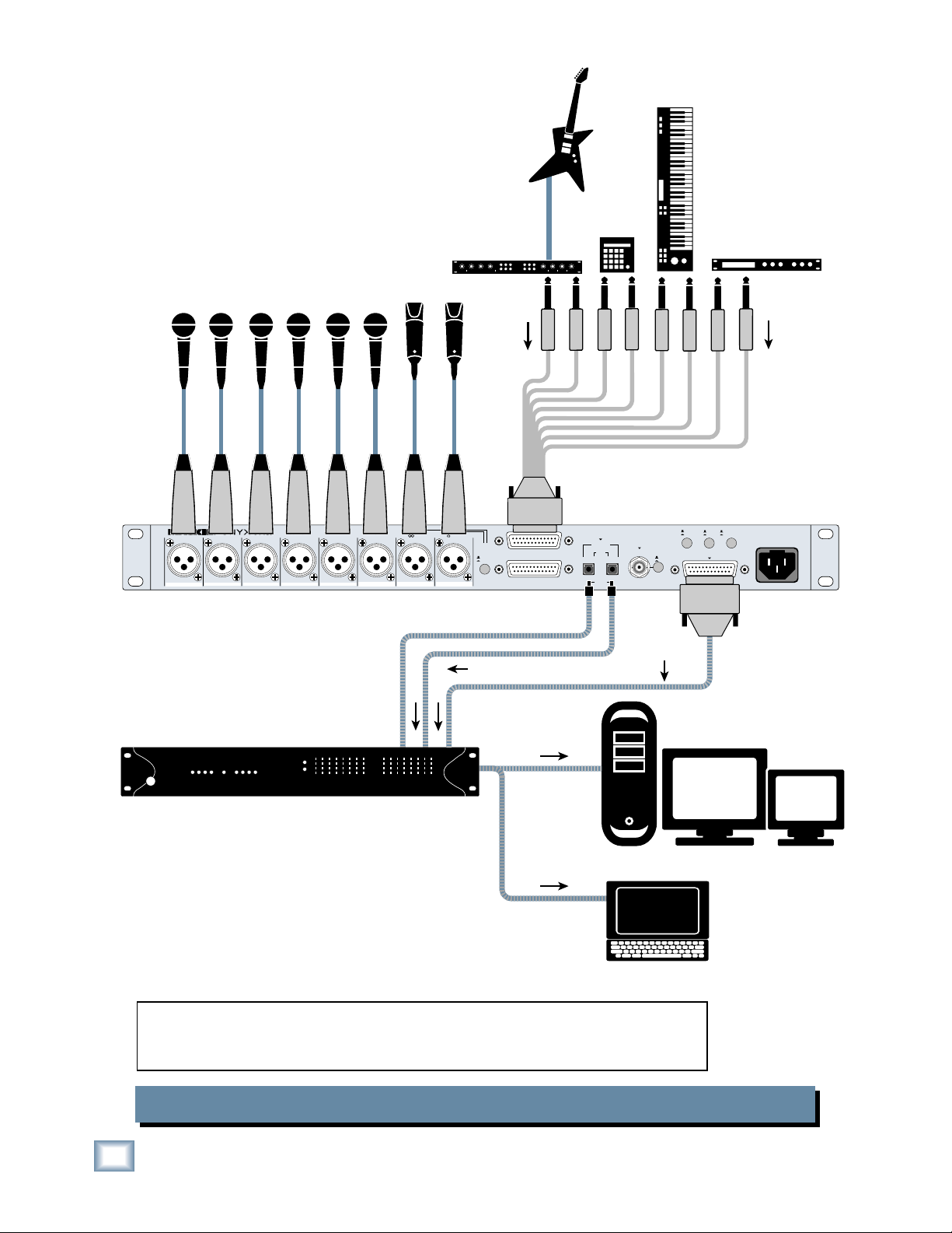
The OPTICAL OUTs or AES/EBU OR S/PDIF OUTs on the Onyx 800R can be connected directly to
a digital audio interface for a
DAW (Digital Audio Workstation).
In this example, use the MIC/LINE switch for each channel to select between the
microphones and the line-level input instruments.
Onyx 800R Multitrack Recording with a DAW (Tracking)
6
ONYX 800R
Page 7
Bass
Guitar
Electric
Guitar
Mics
Owner’s Manual
Drum
Machine
Keyboard or other
line-level input
HI-Z
INPUTS
(on front
panel)
M
X
I
C
Y
P
N
R
O
E
87654321
X
X
I
I
C
C
Y
Y
N
O
P
P
N
R
R
O
E
M
M
Portastudio
with ADAT Optical Inputs
ANALOG MICROPHONE PREAMP WITH 192kHz DIGITAL OUTPUT
M
M
X
X
I
C
Y
P
N
R
O
E
E
X
I
C
Y
Y
P
N
N
R
O
O
E
Input 5 Input 6
DUAL WIRE
110Ω
PRO
75Ω
CONS
AES/EBU OR S/PDIF OUT
AES/EBU = 110Ω / PRO
SPDIF = 75Ω / CONSUMER
SINGLE WIRE
100-240 VAC
~
50-60Hz 105W
OPTICAL OUT
SIDE MID
M
M
M
X
I
C
P
R
E
X
I
I
C
C
Y
Y
P
N
O
P
N
R
R
O
E
E
MID/SIDE
BALANCED LINE LEVEL
DECODE
NORMAL
MID/SIDE
INPUT
BALANCED LINE LEVEL
OUTPUT
1-8 1-81-4 5-8
EXTERNAL
WORD
CLOCK IN
44.1/48kHz
88.2/
96kHz
1-2
176.4/
192kHz
TERMINATION
OFF
ON (75Ω)
3-4
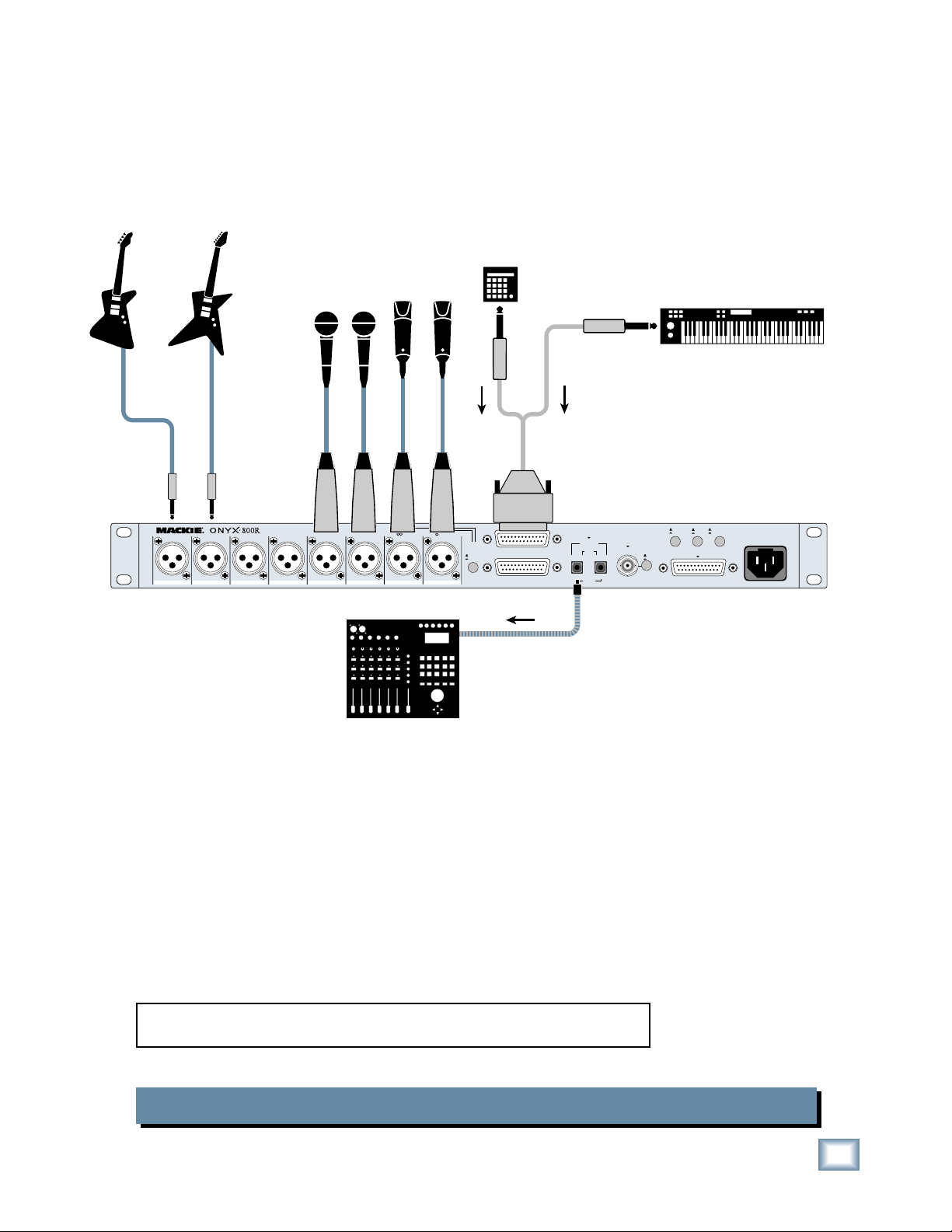
The OPTICAL OUT on the Onyx 800R can be connected directly to a
tastudio with ADAT optical inputs.
Onyx 800R Multitrack Recording with a Portastudio (Tracking)
por-
Owner’s Manual
7
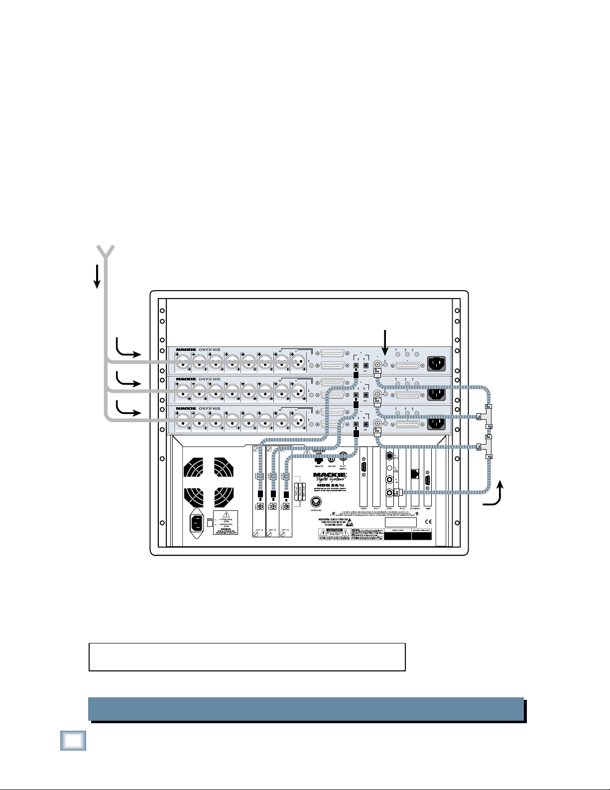
Page 8
ONYX 800R
f
k
24-Channels
rom On-Stage
Mic Splitter
ANALOG MICROPHONE PREAMP WITH 192kHz DIGITAL OUTPUT
M
M
X
I
C
Y
P
N
O
M
X
I
C
Y
P
N
O
M
X
I
C
Y
P
N
O
X
X
I
I
C
C
Y
Y
P
P
N
N
R
R
O
O
E
E
87654321
M
M
X
X
I
I
C
C
Y
Y
P
P
N
N
R
R
O
O
E
E
87654321
M
M
X
X
I
I
C
C
Y
Y
P
P
N
N
R
R
O
O
E
E
87654321
M
M
M
X
X
I
I
C
C
Y
Y
P
P
N
N
R
R
O
O
E
E
ANALOG MICROPHONE PREAMP WITH 192kHz DIGITAL OUTPUT
M
M
X
X
I
I
C
C
Y
Y
P
P
N
N
R
R
O
O
E
E
ANALOG MICROPHONE PREAMP WITH 192kHz DIGITAL OUTPUT
M
M
X
X
I
I
C
C
Y
Y
P
P
N
N
R
R
O
O
E
E
SIDE MID
M
M
X
X
I
I
C
C
Y
Y
P
P
N
N
R
R
E
R
E
R
E
R
O
O
E
E
SIDE MID
M
M
X
X
I
I
C
C
Y
Y
P
P
N
N
R
R
O
O
E
E
SIDE MID
M
M
X
X
I
I
C
C
Y
Y
P
P
N
N
R
R
O
O
E
E
Push In Termination Button
on Last Onyx 800R
DUAL WIRE
110Ω
PRO
75Ω
CONS
OPTICAL OUT
EXTERNAL
M
X
I
C
Y
P
N
R
O
E
MID/SIDE
BALANCED LINE LEVEL
DECODE
INPUT
NORMAL
MID/SIDE
BALANCED LINE LEVEL
OUTPUT
M
X
I
C
Y
P
N
R
O
E
MID/SIDE
BALANCED LINE LEVEL
DECODE
INPUT
NORMAL
MID/SIDE
BALANCED LINE LEVEL
OUTPUT
M
X
I
C
Y
P
N
R
O
E
MID/SIDE
BALANCED LINE LEVEL
DECODE
INPUT
NORMAL
MID/SIDE
BALANCED LINE LEVEL
OUTPUT
1-8 1-81-4 5-8
1-2
OPTICAL OUT
1-8 1-81-4 5-8
1-2
OPTICAL OUT
1-8 1-81-4 5-8
1-2
WORD
CLOCK IN
44.1/48kHz
88.2/
TERMINATION
96kHz
3-4
176.4/
192kHz
EXTERNAL
WORD
CLOCK IN
44.1/48kHz
88.2/
TERMINATION
96kHz
3-4
176.4/
192kHz
EXTERNAL
WORD
CLOCK IN
44.1/48kHz
88.2/
TERMINATION
96kHz
3-4
176.4/
192kHz
OFF
ON (75Ω)
OFF
ON (75Ω)
OFF
ON (75Ω)
AES/EBU OR S/PDIF OUT
AES/EBU = 110Ω / PRO
SPDIF = 75Ω / CONSUMER
110Ω
PRO
75Ω
CONS
AES/EBU OR S/PDIF OUT
AES/EBU = 110Ω / PRO
SPDIF = 75Ω / CONSUMER
110Ω
PRO
75Ω
CONS
AES/EBU OR S/PDIF OUT
AES/EBU = 110Ω / PRO
SPDIF = 75Ω / CONSUMER
SINGLE WIRE
DUAL WIRE
SINGLE WIRE
DUAL WIRE
SINGLE WIRE
100-240 VAC
~
50-60Hz 105W
100-240 VAC
~
50-60Hz 105W
100-240 VAC
~
50-60Hz 105W
Word Cloc
Out
You can use mic splitters to route the signals from the stage to three
Onyx 800Rs in a rack, for 24-track live recording to a Mackie HDR.
Onyx 800R Live Multitrack Recording with an HDR
8
ONYX 800R
Page 9

Owner’s Manual
p
r
INPUTS
(on front
panel)
Electric
Guitar
Stereo Guitar Effects
HI-Z
Bass
Guitar
Electric
Guitar
M
M
X
X
I
I
C
C
Y
Y
P
P
N
N
R
R
O
O
E
E
87654321
Vocal Mics
ANALOG MICROPHONE PREAMP WITH 192kHz DIGITAL OUTPUT
M
M
X
X
I
I
C
C
Y
Y
N
O
Y
P
P
N
N
R
R
O
O
E
E
M
M
X
X
I
I
C
C
Y
P
N
R
O
E
Onyx 800R With Remarkable Mic Pre's
DUAL WIRE
110Ω
PRO
75Ω
CONS
OPTICAL OUT
1-8 1-81-4 5-8
1-2
EXTERNAL
WORD
CLOCK IN
44.1/48kHz
88.2/
TERMINATION
96kHz
3-4
176.4/
192kHz
SIDE MID
M
M
X
X
I
I
C
C
Y
Y
P
P
P
N
N
R
E
R
R
O
O
E
E
MID/SIDE
BALANCED LINE LEVEL
DECODE
INPUT
NORMAL
MID/SIDE
BALANCED LINE LEVEL
BALANCED LINE LEVEL
OUTPUT
OUTPUT
OFF
ON (75Ω)
AES/EBU OR S/PDIF OUT
AES/EBU = 110Ω / PRO
SPDIF = 75Ω / CONSUMER
SINGLE WIRE
100-240 VAC
~
50-60Hz 105W
Mixer With Unremarkable
Mic Pre's
This hookup diagram demonstrates how you can use the balanced linelevel outputs on the Onyx 800R in a live mixing application.
Onyx 800R Live Mixing
Left PA S
Stereo EQ
Stereo Power
Amplifier
Right PA Speake
eaker
Owner’s Manual
9
Page 10

Onyx 800R Features
z
Front Panel
There are eight channels in the Onyx 800R. They
all share the same features with the exceptions that
channels 1 and 2 have an impedance select switch and
a mid/side decode switch, and channels 7 and 8 have a
ONYX 800R
high-impedance 1/4" input jack for connecting electric
instruments directly to the preamp without a direct box.
1. GAIN Control
The GAIN control adjusts the input sensitivity of the mic
and line inputs. This allows the signal from the outside
world to be adjusted to optimal internal operating levels.
If the signal is plugged into the XLR jack, there is 0 dB
of gain (unity gain) with the knob turned all the way
down, ramping up to 60 dB of gain fully up.
When connected to the balanced line input (DB25
connector), there is 20 dB of attenuation all the way
down, and 40 dB of gain fully up, with a “U” (unity gain)
mark at about 10:00.
2. MIC/LINE Switch
This button selects the input source from either the
XLR MIC inputs or the DB25 LINE inputs. When the button is out, the XLR MIC input is used and the line input
is disconnected. When the button is pushed in, the DB25
LINE input is used and the XLR MIC input is disconnected. This way, you can leave signals connected to both
inputs without having to disconnect one or the other,
and the 800R acts as a patchbay for your input sources.
3. MIC IMPEDANCE Switch (Channels 1 and 2)
Many classic, vintage, and ribbon microphones are
sensitive to the input impedance of the mic preamp, and
operate best at specifi c impedances. The MIC IMPED-
very
ANCE switch allows you to change the input impedance
of the microphone inputs on channels 1 and 2. This
allows you to change the characteristics of the sound of
the microphone.
There are four selections to choose from: A: 300 ohms,
B: 500 ohms, C: 1300 ohms, and D: 2400 ohms. Select the
impedance that is closest to the recommended impedance for your microphone. Or you can experiment with
different settings and decide which one sounds best for
your particular application.
Note: The 2400 ohm position (D) matches the nominal input impedances of channels 3-8.
4. Phase Switch
Pushing in this switch simply reverses the polarity of the
signal. This provides an easy way to correct a microphone
whose polarity is opposite from the other microphones,
either from a miswired cable or from not following the AES
standard for Pin 2/Pin 3.
5. Low-Cut Switch
The Low-Cut switch, often referred to as a high-pass
fi lter, cuts bass frequencies below 75 Hz at a rate of 18 dB
per octave.
+15
+10
+5
0
–5
–10
–15
20Hz100
Low Cut
Hz
1k
Hz
In live situations, this is
useful for removing microphone handling noise or
stage rumble. It can also be
used to reduce the “proximity effect” with certain
microphones that accentu-
10kHz20k
H
ates the bass frequencies
when a vocalist gets too
close to the microphone.
10
Channel 1
-
20 MIDOL0-20
0
GAIN
30
U
20
U
-20dB
+40dB
ONYX 800R
Channel 8
HI-Z
MIC/LINE
HI-Z (INST)
88
11MIDOL0
Ω
A
300
B
48V
40
LINE
60
500Ω
130 0 Ω
2400 Ω
A
B
MIC
IMPEDANCE
C
D
C
D
-20dB
OL0-20 OL0-20
40
60
+40dB
48V
LINE
UNBAL
0
GAIN
30
U
20
U
Page 11

6. 48V Phantom Power Switch
Most professional condenser microphones require
phantom power, which is a low-current DC voltage
delivered to the microphone on pins 2 and 3 of the XLR
microphone connector. Push in the 48V button if your
microphone needs phantom power. An LED lights next
to the button to indicate that phantom power is active
on that channel.
Dynamic microphones, like Shure’s SM57 and SM58,
do not require phantom power. However, phantom
power will not harm most dynamic microphones should
you accidentally plug one in while the phantom power
is turned on. Be careful with older ribbon microphones.
Check the manual for your microphone to fi nd out for
sure whether or not phantom power can damage it.
7. Signal Level LEDs
These LEDs indicate the channel’s signal level after
the GAIN control.
If you’ve followed the “Set the Levels” procedure on
page 5, the –20 and 0 LEDs should light frequently, and
the OL (Overload) LED should not light at all. If the
OL LED is blinking frequently, the signal is probably
distorted from overdriving the input. Either turn down
the GAIN control or turn down the signal at its source.
HOWEVER: The HI-Z inputs are unbalanced, so if you’re
doing a live show and running a long cord between the
instrument and the mixer (say over 25 or 30 feet), it is
best to use a direct box with a balanced output to avoid
picking up noise over the length of the cord.
10. POWER Switch
This one is self-explanatory. When the POWER switch
is turned ON (up), power is supplied to the Onyx 800R.
11. SAMPLE RATE Switch
Turn this switch to select the sample rate used by the
analog-to-digital converters (ADCs) and the digital output.
This eight-position switch offers the following selections:
32 kHz, 44.1 kHz, 48 kHz, 88.2 kHz, 96 kHz, 176.4 kHz, 192
kHz, and EXTERNAL. The LED next to the selected sample
rate lights to indicate the sample rate currently being used.
If EXTERNAL is selected, the 800R locks to the external clock connected to the EXTERNAL WORD CLOCK
IN connector [19] on the rear panel.
For any of the internal sample rate settings, the ADAT
OPTICAL OUT and the AES/EBU OR S/PDIF OUT run
at the selected sample rate, which is detected by the
device to which the Onyx 800R is connected.
Owner’s Manual
8. UNBAL HI-Z Instrument Input (Channels 7-8)
This is a 1/4" connector, which accepts an unbalanced
instrument-level input
instrument
like a guitar.
signal from a high-impedance
9. MIC/LINE/HI-Z (INST) Switch
Channels 7 and 8 have an extra button for switching
between the MIC/LINE and HI-Z inputs. When the button is out (MIC/LINE), the XLR MIC input or the DB25
LINE input is used, depending on the setting of the
MIC/LINE switch [2], and the HI-Z input is disconnected. When the button is pushed in (HI-Z), the 1/4" HI-Z
input is used and the XLR MIC and DB25 LINE inputs
are disconnected. The input stage of the HI-Z inputs is
specially designed for the high-impedance pickups on
electric guitars, basses, acoustic guitar pickups, etc.
Plugging a guitar straight into a typical line input can result in the loss of
high frequencies, causing an unnatural
and dull sound. Normally, you must use
a direct box between a guitar and a
mixer’s or preamplifi er’s input, which serves to convert
the impedance of the guitar from high to low. The HI-Z
inputs on channels 7 and 8 make the need for a direct
box unnecessary.
12. LOCK
As described above, if EXTERNAL SAMPLE RATE is
selected, the 800R locks to the the EXTERNAL WORD
CLOCK IN on the rear panel. If there is not a valid clock
connected to the EXTERNAL WORD CLOCK IN, the
LOCK LED fl ashes, indicating the problem. If a valid ex-
ternal clock is detected, the LOCK LED lights continuously and the corresponding sample rate LED will light.
13. BIT DEPTH
This button determines the word length at the digital
output, and toggles between 24-bit and 16-bit. The
corresponding LED above the button lights to indicate
the selection. You might use 24-bit when recording to a
24-track hard disk recorder or DAW, and 16-bit when recording direct to 2-track on a CD-recorder or DAT deck.
When 16-bit is selected, a dithering algorithm is applied
to the digital signal to improve the dynamic range and
reduce low-level distortion, called quantization noise.
ANALOG MIC PREAMP WITH 192kHz DIGITAL OUTPUTANALOG MIC PREAMP WITH 192kHz DIGITAL OUTPUT
ON
32kHz
96kHz
44.1kHz
176.4kHz
48kHz
192 kHz
EXTERNAL
88.2kHz
LOCK
SAMPLE RATE
Owner’s Manual
24
BIT16BIT
(DITHER)
BIT
DEPTH
11
Page 12

Rear Panel
15. MID/SIDE DECODE
The rear panel is where you make all your analog and
digital audio connections to the Onyx 800R (except for
the high-impedance instrument jacks on the front).
14. MIC Inputs
These are female XLR connectors, which accept a
ONYX 800R
balanced microphone input from almost any type of
microphone. The microphone preamps feature our new
Onyx design, with higher fi delity and headroom rivaling
any standalone mic preamp on the market today.
The XLR inputs are wired as follows:
Pin 1 = Shield or ground
Pin 2 = Positive (+ or hot)
Pin 3 = Negative (– or cold)
A CLOSER LOOK AT MID/SIDE RECORDING
A number of stereo recording techniques have
been developed over the years including Blumlein,
ORTF, spaced pair, and coincident pair, of which X-Y
and M-S are a subset. They each have their advantages, depending on the application. Let’s look at what
the M-S method has to offer.
The Onyx 800R has a built-in Mid/Side decoder for
stereo mic’ing. The Mid/Side (or M-S) stereo mic’ing
technique not only provides a stereo image of the
source, but allows you to adjust the width of the image
by varying the balance between the Mid (or mono) and
Side signals. See “A Closer Look at Mid/Side Recording”
below for more info.
When using this technique, connect a cardioid (mid)
microphone to channel 1 and a fi gure 8 (side) micro-
phone to channel 2. Push in the MID/SIDE DECODE
button, and the left signal from the decoder is sent to
the channel 1 output, and the right signal from the
decoder is sent to the channel 2 output.
The Onyx 800R has a decoder built-in, which is
activated by pushing in the MID/SIDE DECODE button on the rear panel. Connect the MID microphone
to channel 1 and the SIDE microphone to channel
2. The signals pass through the decoder just prior to
the A/D converters and the analog line outputs.
M-S (Mid-Side) requires the use of two microphones, one with a cardioid pickup and one with
a fi gure-8 (bidirectional) pattern. The cardioid
microphone (mid) faces straight forward toward the
center of the sound source, while the fi gure-8 (side)
microphone’s two elements face sideways, perpendic-
ular to the mid microphone. It is important that the
null of the fi gure 8 mic aligns with the zero degree
line of the cardioid.
+=
FIGURE 8CARDIOID
Some microphone manufacturers make stereo mics
designed specifi cally for M-S recording, with all three
elements properly aligned in one housing. There’s
nothing wrong with using two separate microphones,
however, as long as the capsules are as coincident
(occupying the same space) as possible.
The M-S technique requires a special decoder
that produces a left and right stereo signal. The left
channel is the sum of the mid and side microphones
(M+S), and the right channel is the difference between the mid and side microphones (M-S).
SIDE
MID
0°
+–
Stereo recording reproduces the instruments in
the same relative locations within the stereo image
as they were in the original performance. The side
to side stereo image and, to some extent, the front to
back depth of image are preserved.
The M-S stereo recording technique allows you
to adjust the width of the stereo image by varying
the ratio between the mid and side signals. With
the 800R, this is accomplished by adjusting the gain
controls on channels 1 and 2.
Notice that the adjustments are made prior to the
decoder. Adjusting the ratio of the left and right signals after the decoder will not have the same effect.
If you want to adjust the stereo image later during
mixdown, record the raw MID and SIDE signals to
tape with the decoder turned off. Then, when you are
doing the fi nal mix, run the recorded MID and SIDE
signals through channels 1 and 2 with the decoder
turned on and experiment with the gain controls on
channels 1 and 2 to adjust the stereo image to your
liking.
Another benefi t of this recording technique is that
the stereo recording is mono compatible. This is
especially important for broadcast and fi lm produc-
tion applications.
12
ONYX 800R
Page 13

16. BALANCED LINE LEVEL INPUT
Owner’s Manual
19. EXTERNAL WORD CLOCK IN
This is a DB25 connector, which accepts eight balanced
line-level input signals from almost any source.
This uses the TASCAM standard pin confi guration for
balanced analog audio signals (the same standard used
on the analog cards for the Mackie D8B and Hard Disk
Recorders). Use the LINE switch on the front panel to
select these line-level inputs instead of the MIC inputs.
See Appendix B for a wiring diagram of this connector.
17. BALANCED LINE LEVEL OUTPUT
This is a DB25 connector, which provides balanced
line-level analog outputs for channels 1-8. It uses the
same TASCAM standard pin confi guration as the linelevel inputs, and is designed to connect directly to a
recorder’s analog inputs. These outputs are always active
regardless of what is happening with the digital outputs.
See Appendix B for a wiring diagram of this connector.
18. OPTICAL OUT
These two Toslink connectors provide a digital output
using the ADAT lightpipe format. At higher sample rates,
the signal is multiplexed using the S/MUX format.
This BNC connector receives word clock from another
device when the SAMPLE RATE selector on the front panel
is set to EXTERNAL. Use this connector when you have multiple devices that must all operate from a master word clock.
Use 75 Ω coaxial cable when connecting
a word clock to the EXTERNAL WORD
CLOCK IN jack. If there is more than
one device to connect to the word clock,
either use a master word clock distribution box, which distributes the master word clock to multiple devices, or use a BNC T-adapter to feed the signal on
to the next device in the chain (see illustrations below).
Word Clock
Distribution Amplifier
Onyx 800R
Word Clock to Other Slaves
(The last device must be terminated)
EXTERNAL
WORD
BNC T-Adapter
CLOCK IN
At 32 kHz, 44.1 kHz, and 48 kHz sample rates: All eight
channels are provided on both connectors.
TIP: If you are recording a live show, you can use the
second OPTICAL OUT to make a backup recording, “just
in case.”
At 88.2 kHz and 96 kHz sample rates: Channels 1-4 are
provided on the left connector, and channels 5-8 are provided on the right connector, as specifi ed by the S/MUX II
protocol for doubled sample rates.
At 176.4 kHz and 192 kHz sample rates: Channels 1-2
are provided on the left connector, and channels 3-4
are provided on the right connector, as specifi ed by the
S/MUX IV protocol for quadrupled sample rates.
If you want to use the higher sample
rates, check your recording device’s
owner’s manual to make sure the optical inputs support the S/MUX format.
ANALOG MICROPHONE PREAMP WITH 192kHz DIGITAL OUTPUT
M
M
M
M
X
I
C
Y
P
N
R
O
O
E
87654321
X
X
Y
N
I
I
C
C
Y
P
P
N
R
R
E
O
O
E
M
X
X
I
I
C
Y
N
C
Y
P
P
N
N
R
R
O
E
O
E
SIDE MID
M
M
X
I
C
Y
P
N
R
O
E
M
X
X
I
I
C
Y
C
Y
P
P
N
R
R
O
E
E
Word Clock From Master
20. TERMINATION
When connecting devices to a word clock, it is important that the connection is properly terminated. If an
Onyx 800R is the only device connected to a word clock
output, push in the TERMINATION button to terminate
the connection with 75 ohms impedance.
If two or more Onyx 800Rs (or other devices) are connected to a word clock output in a daisy-chain fashion,
as illustrated in the hookup diagram on page 8, leave the
termination button out on all the Onyx 800Rs except for
the last one in the chain. Remember, the last device in the
chain is the one that should be terminated with 75 ohms.
DUAL WIRE
110Ω
PRO
75Ω
CONS
MID/SIDE
DECODE
NORMAL
MID/SIDE
BALANCED LINE LEVEL
INPUT
BALANCED LINE LEVEL
OUTPUT
OPTICAL OUT
44.1/48kHz
88.2/
96kHz
1-8 1-81-4 5-8
1-2
176.4/
192kHz
EXTERNAL
WORD
CLOCK IN
TERMINATION
OFF
ON (75Ω)
3-4
AES/EBU OR S/PDIF OUT
AES/EBU = 110Ω / PRO
SPDIF = 75Ω / CONSUMER
SINGLE WIRE
~
50-60Hz 105W
100-240 VAC
Owner’s Manual
13
Page 14

21. AES/EBU OR S/PDIF OUT
This DB25 connector produces a digital output for all
eight channels in either AES/EBU format (PRO) or S/PDIF
format (CONS). The audio data is the same for either
format, but the electrical characteristics (voltage level, impedance) and non-audio data bits (subcode) are different.
This can be connected directly to a recording device
with AES/EBU or S/PDIF inputs using an appropriate
ONYX 800R
digital recorder interface cable.
By the way, the most wonderful thing
about standards is that there are so
many to choose from. A variety of
alternate pin-out confi gurations are
being used by various manufacturers for the AES/EBU DB25 interface. You will need to
make a conversion cable when connecting between two
devices that use different pin-outs for the AES/EBU or
S/PDIF DB25 connectors. See Appendix B for a wiring
diagram of this connector.
For AES/EBU connections:
Note: Transferring digital audio over a
cable generates EMI (electromagnetic
interference) around the cable. Use a
high-quality shielded cable to mini-
mize the EMI noise radiated around
the cable. For example, Belden’s 7880A cable shields each
individual pair of wires as well as the entire cable, and is
recommended by Belden for AES/EBU digital audio.
In general, the shorter the cable length,
the less effect it has on the quality of
the signal. The maximum length for an
AES/EBU cable is 100 meters (about
325 feet), and a S/PDIF cable is limited
to 10 meters (about 32 feet).
The three buttons located just above the AES/EBU
OR S/PDIF OUT connector can be used to customize the
digital signal. The 110Ω/75Ω and PRO/CONS buttons
in particular give you added fl exibility when interfacing
with “fi nicky” digital inputs.
22. 110Ω/75Ω Switch
1. Most devices use a balanced 3-pin XLR connector
for two-channel inputs, or a 25-pin DB25 connector for
eight channels. Special AES/EBU cables are available
from various manufacturers with DB25 connectors on
both ends, or breakout cables are available for making
digital audio connections from DB25 to XLR.
These off-the-shelf cable harnesses have four male
XLRs for the outputs, and four female XLRs for the inputs. Since the Onyx 800R only has digital outputs, you
won’t use the female connectors.
2. If you want a more streamlined cable harness, you
can make your own (or have one made) with only the
four connectors.
For S/PDIF connections:
1. Most devices use an RCA connector for two-channel
inputs, or a 25-pin DB25 connector for eight channels.
Your best option for connecting to devices with RCA
jacks is to use an AES/EBU breakout cable described
above, and fi t it with XLR-to-RCA adapters (or build
your own custom cable harness with four RCA connectors on it). Use a DB25-to-DB25 AES/EBU cable for
devices with DB25 S/PDIF connections.
If you are using the AES/EBU format, the output is a
balanced differential signal at a voltage specifi ed at be-
tween 2 to 7 V peak-to-peak into 110 ohms. In the S/PDIF
format, the output signal is unbalanced at a voltage of 0.5
V peak-to-peak into 75 ohms. So use the 110Ω position
for AES/EBU, and the 75Ω position for S/PDIF.
Note: If you are using any kind of adapter to convert an
AES/EBU connector to a S/PDIF connector, check to see
if the adapter converts the impedance as well as the connector type. If this is the case, leave the 110Ω/75Ω switch
in the 110Ω position. Only use the 75Ω position with true
75-ohm coaxial cable connected directly to a S/PDIF input.
23. PRO/CONS Switch
Use this switch to select between the professional
AES/EBU format or the consumer S/PDIF format.
Note: Strictly speaking, AES/EBU can transmit up to
24-bits, while S/PDIF is limited to 20-bits because four
bits are reserved for “user bits.” However, if 24-bit depth
is selected, the four user bits are used for digital audio
and 24-bits are transmitted (this is an accepted optional
implementation of S/PDIF).
14
ANALOG MICROPHONE PREAMP WITH 192kHz DIGITAL OUTPUT
M
M
M
M
X
I
C
Y
P
N
R
O
O
E
87654321
X
X
Y
N
I
I
C
C
Y
P
P
R
E
N
N
R
O
O
E
M
X
X
I
I
C
Y
C
Y
P
P
N
N
R
R
O
E
O
E
SIDE MID
M
M
X
I
C
Y
P
R
O
E
X
X
I
C
Y
Y
P
N
N
R
O
E
ONYX 800R
DUAL WIRE
110Ω
PRO
75Ω
CONS
AES/EBU OR S/PDIF OUT
AES/EBU = 110Ω / PRO
SPDIF = 75Ω / CONSUMER
SINGLE WIRE
100-240 VAC
~
50-60Hz 105W
OPTICAL OUT
EXTERNAL
M
I
C
P
R
E
MID/SIDE
BALANCED LINE LEVEL
DECODE
NORMAL
MID/SIDE
INPUT
BALANCED LINE LEVEL
OUTPUT
1-8 1-81-4 5-8
1-2
44.1/48kHz
96kHz
176.4/
192kHz
WORD
CLOCK IN
88.2/
TERMINATION
OFF
ON (75Ω)
3-4
Page 15

24. DUAL WIRE/SINGLE WIRE Switch
Owner’s Manual
The original AES/EBU specifi cation (IEC958 Type 1)
provides for carrying two channels of digital audio at
resolutions up to 24-bit at 48 kHz. When higher sampling rates became possible, two methods were developed to transmit the digital audio at the higher sample
rates—double-fast and double-wide.
The double-fast method (single wire) clocks the
digital I/O port at twice the speed to get twice the information through, providing support for resolutions up to
24-bit at 96 kHz.
The double-wide method (dual wire) transmits one
channel of digital audio instead of two channels through
a single digital I/O port, again providing support for
resolutions up to 24-bit at 96 kHz.
This presents a problem when interconnecting digital
audio equipment. Devices using the double-fast method
can’t talk to devices using the double-wide method.
Remember the old Beta vs. VHS format wars? Maybe
not. Well, the Onyx 800R has solved this dilemma with
the fl ip of a switch! Here’s how it works:
At sampling rates up to 48 kHz: The position of the
DUAL WIRE/SINGLE WIRE switch doesn’t matter. Two
channels of digital audio are transmitted on a single wire
(one 3-pin XLR) as specifi ed by the AES/EBU standard.
Check the owner’s manual for the device you are connecting to the Onyx 800R, to fi nd out which method it
supports.
Note: The analog and optical outputs are not affected
by the AES/EBU OR S/PDIF OUT settings.
25. Power Receptacle
This is a standard 3-prong IEC power connector.
Connect the detachable linecord (included in the box
with your Onyx 800R) to the power receptacle, and plug
the other end of the linecord into an AC outlet. The
Onyx 800R has a universal power supply that can accept
any AC voltage ranging from 100 VAC to 240 VAC. No
need for voltage select switches. It will work virtually
anywhere in the world. That’s why we call it a “PlanetEarth” power supply! This also means that it is less
susceptible to voltage sags or spikes, providing greater
electromagnetic isolation and better protection against
AC line noise.
At sampling rates of 88.2 kHz through 192 kHz: When
connecting to devices that use the double-fast method,
set the switch to the SINGLE WIRE position. This
transmits two channels on a single wire (3-pin XLR) at
twice the speed (88.2/96 kHz) or four times the speed
(176.4/192 kHz). When connecting to devices that use
the double-wide method, set the switch to the DUAL
WIRE position. This transmits one channel on one wire
(one 3-pin XLR) at normal speed (88.2/96 kHz) or twice
the speed (176.4/192 kHz), but using twice the bandwidth. In the DUAL WIRE position at these sampling
rates, only channels 1-4 are available.
CH
1-2CH3-4CH5-6CH7-8
CH
1-2CH3-4CH5-6CH7-8
CH1CH2CH3CH
4
Single Wire
(Two-Channel)
@ 44.1/48 kHz (1x)
Single Wire
(Two-Channel)
(Double-Fast)
@ 88.2/96 kHz (2x)
@ 176.4/192 kHz (4x)
Dual Wire
(Single-Channel)
(Double-Wide)
@ 88.2/96 kHz (1x)
@ 176.4/192 kHz (2x)
Owner’s Manual
15
Page 16

Appendix A: Service Information
Warranty Service
Details concerning Warranty Service are spelled out in
the Warranty section on page 23.
If you think your Onyx preamp has a problem, please
ONYX 800R
do everything you can to confi rm it before calling for
service. Doing so might save you from the deprivation of
your Onyx preamp and the associated suffering.
These may sound obvious to you, but here are some
things you can check. Read on.
Troubleshooting
No Power
• Our favorite question: Is it plugged in?
• Make sure the power cord is securely seated in the
IEC socket [25] and plugged all the way into the
AC outlet.
• Make sure the AC outlet is live (check with a tester
or lamp).
• Is the POWER [10] switch on? Make sure the
POWER switch on the front panel is in the ON position (up).
• Are any LEDs on the front panel illuminated? If not,
make sure the AC outlet is live.
• Are all the lights out in your building? If so, contact
your local power company to get power restored.
• If there are no LEDs illuminated on the front panel,
and you are certain that the AC outlet is live, it will
necessary to have your Onyx 800R serviced. There
be
are no user serviceable parts inside. Refer to “Repair”
at the end of this section to fi nd out how to proceed.
Bad Channel
• Is the LINE switch [2] in the correct position?
• Is the input GAIN control [1] for the channel
turned up?
• Is the signal source turned up? Make sure the
signal level from the selected input source is high
enough to light up some of the INPUT meter [7]
LEDs for that channel.
If it is channel 7 or 8, make sure the MIC/LINE/HI-Z
•
switch [9] is in the right position.
• Try the same source signal in another channel, set
up exactly like the suspect channel.
Bad Output
• If it’s the BALANCED LINE LEVEL OUTPUT [17],
make sure the DB25 connector is correctly wired
(see Appendix B: Connections).
• If it’s the OPTICAL OUT [18], make sure the optical
cable isn’t kinked or damaged, and that the connectors are securely seated at both ends.
• If it’s the AES/EBU OR S/PDIF OUT [21], make
sure the DB25 connector is correctly wired (see
Appendix B: Connections). Determine if the device
to which the Onyx 800R is connected is operating
in SINGLE WIRE or DUAL WIRE mode. Make sure
the buttons above the AES/EBU OR S/PDIF OUT
connector are in the correct positions.
Bad Sound
• Is the input connector plugged completely into the
jack?
• Is it loud and distorted? Make sure the input GAIN
control for the channel is set correctly. Reduce the
signal level on the input source if possible.
• Are the Onyx 800R and the device to which it is
connected locked to the same clock rate? If the
Onyx 800R is operating on its own internal sample
rate, make sure the device to which it is connected
is set to external clock and is locking to the word
clock either through the OPTICAL or the AES/EBU
OR S/PDIF connections. If the Onyx 800R is set to
EXTERNAL clock, make sure the LOCK LED is lit.
• If possible, listen to the signal with headphones
plugged into the input source device. If it sounds
bad there, it’s not the Onyx causing the problem.
Noise/Hum
• Turn down each channel, one by one. If the noise
disappears, it’s coming from whatever is plugged
into that channel.
• Check the signal cables between the input sources
and the Onyx. Disconnect them one by one. When
the noise goes away, you’ll know which input source
is causing the problem.
• Sometimes it helps to plug all the audio equipment
into the same AC circuit so they share a common
ground.
• Make sure you are using shielded cable designed for
digital audio transmission, like Belden 7880A.
16
ONYX 800R
Page 17

Repair
Owner’s Manual
Service for Mackie products is available at our galactic
headquarters, located in sunny Woodinville, Washington.
Service for Mackie products living outside the United
States can be obtained through local dealers or distributors.
If your Onyx 800R needs service, follow these instructions:
1. Review the preceding troubleshooting suggestions.
Please.
2. Call Tech Support at 1-800-898-3211, 7 am to 5 pm
PST, to explain the problem and request an RA
(Return Authorization) number. Have your Onyx
800R’s serial number ready. You must have an RA
number before you can obtain service at the
factory.
3.
Keep this owner’s manual and the detachable linecord. We don’t need them to repair the mixer.
4. Pack the preamplifi er in its original package,
including endcaps and box. This is VERY IMPOR-
TANT. When you call for the RA number, please
let Tech Support know if you need new packaging.
Mackie is not responsible for any damage that occurs due to non-factory packaging.
7. Ship the preamplifi er to us. We suggest insurance
for all forms of cartage. Ship to this address:
MACKIE
SERVICE DEPARTMENT
16220 Wood-Red Road NE
Woodinville, WA 98072
8. We’ll try to fi x the preamplifi er within three to fi ve
business days. Ask Tech Support for the latest turnaround times when you call for your RA
The preamp must be packaged in its original packing box, and must have the RA number on the box.
Once it’s repaired, we’ll ship it back the same way
in which it was received. This paragraph does not
necessarily apply to non-warranty repair.
Note: You must have a sales receipt from an Autho-
rized Mackie Dealer to qualify for a warranty repair.
number.
5. Include a legible note stating your name, shipping
address (no P.O. boxes), daytime phone
number, and a detailed description of the problem,
including how we can duplicate it.
6.
Write the RA number in BIG PRINT on top of the box.
Units sent to us without the RA number will be refused.
number, RA
Need Help?
You can reach a technical support representative
Monday through Friday
from 7 AM to 5 PM PST at:
1-800-898-3211
After hours, visit www.mackie.com and click Support,
or email us at: techmail@mackie.com
Owner’s Manual
17
Page 18

Appendix B: Connections
P
XLR Connectors
Channels 1-8 use 3-pin female XLR connectors on the
MIC inputs. They are wired as follows, according to standards specifi ed by the AES (Audio Engineering Society).
ONYX 800R
COLD
3
HOT
1
2
HOT
2
1
3
1
3
2
SHIELD
COLD
HOT
SHIELD
SHIELD
COLD
XLR Balanced Wiring:
Pin 1 = Shield
Pin 2 = Hot (+)
Pin 3 = Cold (–)
1/4" TRS Phone Plugs and Jacks
“TRS” stands for Tip-Ring-Sleeve, the three connection
points available on a stereo 1/4" or balanced phone jack
or plug. TRS jacks and plugs are used for balanced signals and stereo headphones. Neither of these are used
on the Onyx 800R, but we’re including them anyway, for
your reference.
Balanced Mono
RING
SLEEVE
SLEEVERING
TIP
1/4" TS Phone Plugs and Jacks
“TS” stands for Tip-Sleeve, the two connection points
available on a mono 1/4" phone jack or plug. They are
used for unbalanced signals like the high-impedance
instrument inputs on the Onyx 800R.
SLEEVE
TIP
SLEEVE
TIP
TIP
SLEEVE
1/4" TS Unbalanced Wiring:
Sleeve = Shield
Tip = Hot (+)
RCA Plugs and Jacks
RCA-type plugs (also known as phono plugs) and jacks
are often used in home stereo and video equipment, and
to make S/PDIF connections on consumer digital audio
devices. They are unbalanced and electrically equivalent to a 1/4" TS phone plug.
TI
SLEEVE
TIPSLEEVE
RCA Unbalanced Wiring:
Sleeve = Shield
Tip = Hot (+)
1/4" TRS Balanced Mono Wiring:
Sleeve = Shield
Tip = Hot (+)
Ring = Cold (–)
Stereo Headphones
1/4" TRS Stereo Unbalanced Wiring:
Sleeve = Shield
Tip = Left
Ring = Right
18
ONYX 800R
TIP
RING
TIP
SLEEVE
Unbalancing a Line
In most studio, stage, and sound reinforcement situations, there is a combination of balanced and unbalanced inputs and outputs on the various pieces of
equipment. This usually will not be a problem in making
connections.
• When connecting a balanced output to an unbal-
anced input, be sure the signal high (hot) connec-
SLEEVERING
TIP
TIP
RING
TIP
SLEEVE
RING
SLEEVE
tions are wired to each other, and that the balanced
signal low (cold) goes to the ground (earth)
connection at the unbalanced input. In most cases,
the balanced ground (earth) will also be connected
to the ground (earth) at the unbalanced input. If
there are ground-loop problems, this connection
may be left disconnected at the balanced end.
Page 19

Owner’s Manual
• When connecting an unbalanced output to a bal-
anced input, be sure that the signal high (hot)
connections are wired to each other. The unbalanced ground (earth) connection should be wired
to the low (cold) and the ground (earth) connections of the balanced input. If there are ground-loop
problems, try disconnecting the unbalanced ground
(earth) connection from the balanced input ground
(earth) connection, leaving the unbalanced ground
connected to the balanced input low (cold) connection only.
In some cases, you may have to make up special
adapters to interconnect your equipment. For example,
you may need a balanced XLR female connected to an
unbalanced 1/4" TS phone plug. Many common adapters
can be found at your local electronics supply store.
DB25 Connectors
Analog
The BALANCED LINE LEVEL INPUTs and BALANCED
LINE LEVEL OUTPUTs on the back of the Onyx 800R
provide balanced inputs and outputs for channels 1-8
on two female DB25 connectors. These connectors are
pin-for-pin compatible with the analog (not TDIF) DB25
connectors found on TASCAM DTRS recorders, which has
become an industry standard for many professional audio
manufacturers. They are also the same pinout as the
analog cards for the Mackie D8B and hard disk recorders.
Digital
The AES/EBU OR S/PDIF OUT connector provides
a digital output for all eight channels. If you have this
output confi gured for AES/EBU, which is a balanced
output, the connector is wired as follows:
INPUTS NOT
USED ON
ONYX 800R
(110 Ω TERMINATION)
CH 3/4 IN–
CH 5/6 IN+
CH 5/6 IN–
CH 7/8 IN+
CH 7/8 IN–
CH 1/2 OUT+
CH 1/2 OUT–
CH 3/4 OUT+
CH 3/4 OUT–
CH 5/6 OUT+
CH 5/6 OUT–
CH 7/8 OUT+
CH7/8 OUT–
SHIELD
SHIELD
SHIELD
SHIELD
NC
SHIELD
SHIELD
SHIELD
SHIELD
Digital DB25 AES/EBU Output
If you have this output confi gured for S/PDIF, which is
an unbalanced output, the connector is wired as follows:
INPUTS NOT
USED ON
ONYX 800R
(110 Ω TERMINATION)
NC
NC
NC
NC
NC
CH 1/2 OUT
CH 1/2 GND
CH 3/4 OUT
CH 3/4 GND
CH 5/6 OUT
CH 5/6 GND
CH 7/8 OUT
CH 7/8 GND
SHIELD
SHIELD
SHIELD
SHIELD
NC
SHIELD
SHIELD
SHIELD
SHIELD
CH 1/2 IN+
CH 1/2 IN–
CH 3/4 IN+
12345678910111213
141516171819202122232425
NCNCNC
Each DB25 connector provides eight balanced line-
level inputs or outputs.
CH 1
CH 2 CH 3 CH 4 CH 5 CH 6 CH 7 CH 8
HOT
COLD
GROUND
HOT
COLD
GROUND
HOT
COLD
GROUND
HOT
COLD
GROUND
HOT
COLD
GROUND
HOT
COLD
GROUND
HOT
COLD
GROUND
HOT
COLD
GROUND
N/C
12345678910111213
141516171819202122232425
Analog DB25 Line-Level Input and Output
Several companies make DB25-to-DB25 cables specifi -
cally for audio, with proper shielding to reduce crosstalk
and noise.
DB25 cables that break out to XLR, 1/4" TRS, or TT
connectors for connecting to other mixers or audio gear
are also readily available. See your Mackie dealer for
details.
12345678910111213
141516171819202122232425
Digital DB25 S/PDIF Output
If you are using the DUAL WIRE position with the
higher sample rates (88.2 kHz and up), the same
cabling that you use for the SINGLE WIRE position will
work as long as you have it connected to another device
using the same method.
Note: A variety of alternate pin-out confi gurations
have been developed by various manufacturers for the
AES/EBU DB25 interface. Make sure the device you are
connecting to has the same pin-out confi guration as the
Onyx 800R. If not, you will need to make a conversion
cable so the signals arrive at the correct pins on the
receiving end of the cable.
Owner’s Manual
19
Page 20

Appendix C: Technical Info
Onyx 800R Specifi cations
Frequency Response
Mic Input to Line Output (Gain @ unity):
+0, –0.1 dB, 20 Hz to 30 kHz
ONYX 800R
+0, –3 dB, 10 Hz to 170 kHz
Mic Input to Digital Output (AES, 192 kHz sample rate):
+0, –0.2 dB, 20 Hz to 85 kHz
+0, –1 dB, 10 Hz to 90 kHz
Distortion (THD & IMD)
Mic Input to Line Output (@ +4 dBu output):
@ +4 dBu, preamp at unity gain
THD+N: < 0.002%, 10 Hz to 30 kHz BW, 1kHz input
@ 10mV rms (–37.8 dBu)
SMPTE IMD: < 0.005% (4:1 IMD)
Mic Input to Digital Output (AES, 48 kHz sample rate):
THD+N: < 0.004%, 10mV rms input,
gain at –1 dB FS output
THD+N: < 0.0007%, 20 Hz to 20 kHz BW, 1 kHz input
Dynamic Range
>123 dB (Mic In to Line Out)
>113 dB (through A-to-D converters)
Noise
Signal-to-Noise (A-weighted):
Equivalent Input Noise (E.I.N.), 20 Hz to 20 kHz Bandwidth,
150Ω source impedance:
–129 dBu @ +60 dB gain
Residual Output Noise:
Line Out: < –102 dBu (Channel Gain at unity)
Digital Out (AES, 48 kHz): < –113 dB FS
>103 dB (ref. +4 dBu, Mic In to Line Out, Gain @ unity)
Common Mode Rejection Ratio (CMRR)
Mic In: >60 dB @ 1 kHz, Gain @ maximum
Crosstalk
Mic Input to Line Output:
< –100 dB @ 1 kHz, +10 dBu signal on adjacent
input, 150Ω source impedance
Input Gain Control Range
Mic In: 0 dB to +60 dB
Line In: –20 dB to + 40 dB
Phantom Power
+48 VDC
Equalization
High-Pass Filter: 75 Hz @ 18 dB/octave
Rated Output
Line: +4 dBu
Maximum Rated Output:
+24 dBu @ Balanced Line-Level Outputs
Maximum Input Levels
Mic Input: +22 dBu, Gain @ unity
Inst Input: +21 dBu, Gain @ –20 dB
Line Input: > +22 dBu, Gain @ –20 dB
Input Impedance
Ch 1 and 2 Mic Input:
300Ω, 500Ω, 1.3 kΩ, or 2.4 kΩ balanced
Ch 3 through 8 Mic Input:
2.4 kΩ balanced
Inst Input: 1 MΩ
Line: 20 kΩ balanced, 10 kΩ unbalanced
Output Impedance
Line: 100 Ω balanced
Signal Level LEDs
–20 dBu, 0 dBu (normal operating level), OL = 22 dBu
Sample Frequency Selections
32 kHz, 44.1 kHz, 48 kHz, 88.2 kHz, 96 kHz,
176.4 kHz, 192 kHz, External
Bit Depth Selections
24-bit (full range from converters), 16-bit (dithered)
Analog Input Connectors
Eight balanced XLR mic inputs
Two 1/4" TS high-impedance instrument inputs
One DB25 connector with eight balanced line-level inputs
Analog Output Connectors
One DB25 connector with eight balanced line-level
outputs
Digital Input Connectors
One BNC connector for external word clock input
Digital Output Connectors
Two Toslink Optical Connectors
Both transmit channels 1-8 at 44.1/48 kHz operation
One transmits channels 1-4 and one transmits
channels 5-8 at 88.2/96 kHz operation using
S/MUX standard
One transmits channels 1-2 and one transmits
channel 3-4 at 176.4/192 kHz operation using
S/MUX standard
One DB25 Connector
Transmits AES/EBU or S/PDIF formatted digital
audio with single-wire/dual-wire options available at
all sample rates
20
ONYX 800R
Page 21

AC Power Requirements
Power Consumption: 45 watts
Universal AC Power Supply:
100 VAC – 240 VAC, 50-60 Hz
Physical Dimensions and Weight
Height: 1.75 in/44 mm
Width: 17.75 in/451 mm (main body of unit)
19.00 in/483 mm (with rack ears)
Depth: 14.38 in/365 mm (including front knobs and
rear BNC jack)
Weight: 10.6 lb/4.8 kg
LOUD Technologies Inc. is always striving to improve our products by incorporating new and improved materials, components,
and manufacturing methods. Therefore, we reserve the right to
change these specifi cations at any time without notice.
“Mackie.”, “Onyx,” and the “Running Man” are registered
trademarks of LOUD Technologies Inc. All other brand names
mentioned are trademarks or registered trademarks of their
respective holders, and are hereby acknowledged.
©2004 LOUD Technologies Inc. All Rights Reserved.
Owner’s Manual
14.4 in/365 mm
17.75 in/451 mm
WEIGHT
10.6 lb/
4.8 kg
19.0 in/483 mm
44 mm
1.75 in/
(1 rack space)
Owner’s Manual
21
Page 22

Onyx 800R Block Diagram
48V
Channel 1
ONYX 800R
Mic
Line
48V
Channel 2
Mic
Line
Channels 3-6
Line Inputs
Channels 7-8
0
0
0
0
0
0
3
0
0
4
1
5
3
2
Mic
0
0
3
+
0
0
0
3
0
1
5
+
Impedance
-
0
0
4
2
Mic
Impedance
-
+
-
+
-
2
1
3
2
1
3
48V
2
1
Mic
3
Line
48V
2
1
Mic
3
Line
Line
Line
Mic
Mic
Mic
Line
Mic
Line
Gain
Mic: 0 to +60 dB
Line: –20 to +40 dB
+
-
Gain
Mic: 0 to +60 dB
Line: –20 to +40 dB
+
-
+
-
Mic: 0 to +60 dB
Line: –20 to +40 dB
Hi-Z: –20 to +40 dB
Gain
+
-
Mic/Line
Hi-Z
OL
0
-20
Phase
Low Cut
75Hz
M/S
Matrix
OL
0
-20
Phase
Low Cut
75Hz
OL
0
-20
Phase
Low Cut
75Hz
to A/D
+
Line Out
–
to A/D
+
Line Out
–
Ch 1/Left
to A/D
+
Line Out
–
Ch 2/Right
Line Outputs
OL
0
-20
+
Line Out
Phase
Low Cut
75Hz
–
to A/D
22
MACKIE
ONYX 800R
BLOCK DIAGRAM
(#04/21/04_DF)
ONYX 800R
Hi-Z
Ch 1
Ch 8
A/D
Conversion
24-bit
Dithered 16-bit
88.2 kHz
48 kHz
44.1 kHz
32 kHz
Sample Rate
Word Clock
Termination
Off/75Ω
Word Clock
Input
96 kHz
176.4 kHz
192 kHz
External
FPGA
Single/
Dual
Wire
Lock
Consumer
ADAT
ADAT
1
Optical
ADAT
Out
2
AES/EBU
S/PDIF
Out
Pro/
Impedance
75Ω/110Ω
Page 23

Onyx 800R Limited Warranty
Please keep your sales receipt in a safe place.
Owner’s Manual
A. LOUD Technologies Inc. warrants all materials, workmanship
and proper operation of this product for a period of three years
from the original date of purchase. If any defects are found
in the materials or workmanship or if the product fails to
function properly during the applicable warranty period, LOUD
Technologies, at its option, will repair or replace the product.
This warranty applies only to equipment sold and delivered
within the U.S. by LOUD Technologies Inc. or its authorized
dealers.
B. Failure to register online or return the product registration
card will not void the three-year warranty.
C. Service and repairs of Mackie products are to be performed
only at the factory (see D below) OR at an Authorized Mackie
Service Center (see E below). Unauthorized service, repairs,
or modifi cation will void this warranty. To obtain repairs under
warranty, you must have a copy of your sales receipt from the
store where you bought the product. It is necessary to establish
purchase date and thus determine whether or not your Mackie
product is still under warranty.
D. To obtain factory service:
1. Call Mackie Service at 800/898-3211, 7 AM to 5 PM
Monday through Friday (Pacifi c Time) to get a Return
Authorization (RA). Products returned without an RA number
will be refused.
2. Pack the product in its original shipping carton. If you do
not have the carton, just ask for one when you get your RA
number, and we’ll send a shipping carton out promptly. More
information on packing can be found in the Service section of
this manual. Please seal the Mackie product in a plastic bag.
3. Also include a note explaining exactly how to duplicate
the problem, a copy of the sales receipt with price and date
showing, and your return street address (no P.O. boxes or
route numbers, please!). If we cannot duplicate the problem
or establish the starting date of your Limited Warranty, we
may, at our option, charge for service time.
4. Ship the product in its original shipping carton, freight
prepaid to:
MACKIE SERVICE DEPARTMENT
16220 Wood-Red Road NE
Woodinville, WA, 98072, USA
IMPORTANT: Make sure that the RA number is plainly
written on the shipping carton.
E. To obtain service from an Authorized Mackie Service Center:
1. Call Mackie Service at 800/898-3211, 7 AM to 5 PM
Monday through Friday (Pacifi c Time) to get: 1) The name and
address of your nearest Authorized Mackie Service Center
and 2) A return authorization (RA). You must have an RA
number before taking your unit to a service center.
2. Make sure that you have a copy of your sales receipt from
the store where you bought the product. If you can’t fi nd it,
the Authorized Service Center may charge you for repairs
even if your Mackie product is still covered by the Three-Year
Limited Warranty.
3. Make sure that the problem can be duplicated. If you bring
your Mackie product to an Authorized Service Center and
they can’t fi nd anything wrong with it, you may be charged a
service fee.
4. If the Authorized Mackie Service Center is located in
another city, pack the mixer in its original shipping carton.
More information on packing can be found in the Service
section of this manual.
5. Contact the Authorized Mackie Service Center to arrange
service or bring the Mackie product to them.
F. LOUD Technologies and Authorized Mackie Service Centers
reserve the right to inspect any products that may be the subject
of any warranty claims before repair or replacement is carried
out. LOUD Technologies and Authorized Mackie Service Centers
may, at their option, require proof of the original date of purchase
in the form of a dated copy of the original dealer’s invoice or
sales receipt. Final determination of warranty coverage lies solely
with LOUD Technologies or its Authorized Service Centers.
G. Mackie products returned to LOUD Technologies and deemed
eligible for repair or replacement under the terms of this
warranty will be repaired or replaced within thirty days of receipt
by LOUD Technologies. LOUD Technologies may use refurbished
parts for repair or replacement of any product. Products
returned to LOUD Technologies that do not meet the terms of
this Warranty will not be repaired and returned until payment
is received for labor, materials, return freight, and insurance.
Products repaired under warranty at the factory will be returned
freight prepaid by LOUD Technologies to any location within the
boundaries of the USA.
H. LOUD Technologies warrants all repairs performed for 90
days or for the remainder of the warranty period. This warranty
does not extend to damage resulting from improper installation,
misuse, neglect or abuse, or to exterior appearance. This
warranty is recognized only if the inspection seals and serial
number on the unit have not been defaced or removed.
I. LOUD Technologies assumes no responsibility for the quality
or timeliness of repairs performed by Authorized Mackie Service
Centers.
J. This warranty is extended to the original purchaser and to
anyone who may subsequently purchase this product within the
applicable warranty period. A copy of the original sales receipt is
required to obtain warranty repairs.
K. This is your sole warranty. LOUD Technologies does
not authorize any third party, including any dealer or sales
representative, to assume any liability on behalf of LOUD
Technologies or to make any warranty for LOUD Technologies Inc.
L. THE WARRANTY GIVEN ON THIS PAGE IS THE SOLE
WARRANTY GIVEN BY LOUD TECHNOLOGIES INC. AND IS IN
LIEU OF ALL OTHER WARRANTIES, EXPRESS AND IMPLIED,
INCLUDING THE WARRANTIES OF MERCHANTABILITY AND
FITNESS FOR A PARTICULAR PURPOSE. THE WARRANTY
GIVEN ON THIS PAGE SHALL BE STRICTLY LIMITED IN
DURATION TO THREE YEARS FROM THE DATE OF ORIGINAL
PURCHASE FROM AN AUTHORIZED MACKIE DEALER. UPON
EXPIRATION OF THE APPLICABLE WARRANTY PERIOD, LOUD
TECHNOLOGIES INC. SHALL HAVE NO FURTHER WARRANTY
OBLIGATION OF ANY KIND. LOUD TECHNOLOGIES INC.
SHALL NOT BE LIABLE FOR ANY INCIDENTAL, SPECIAL, OR
CONSEQUENTIAL DAMAGES THAT MAY RESULT FROM ANY
DEFECT IN THE MACKIE PRODUCT OR ANY WARRANTY
CLAIM. Some states do not allow exclusion or limitation of
incidental, special, or consequential damages or a limitation on
how long warranties last, so some of the above limitations and
exclusions may not apply to you. This warranty provides specifi c
legal rights and you may have other rights which vary from state
to state.
Owner’s Manual
23
Page 24

16220 Wood-Red Road NE • Woodinville, WA 98072 • USA
United States and Canada: 800.898.3211
Europe, Asia, Central and South America: 425.487.4333
Middle East and Africa: 31.20.654.4000
Fax: 425.487.4337 • www.mackie.com
E-mail: sales@mackie.com
 Loading...