

Mackie 56-input, 72 channel, fully automated digital audio mixing console, Digital 8-Bus Quick Start Manual
DIGITAL 8•BUS
QUICK START GUIDE
™
MACKIE’S 56-INPUT, 72-CHANNEL, FULLY AUTOMATED DIGITAL AUDIO MIXING CONSOLE

TABLE OF CONTENTS
1. Introduction............................................................................................................. 3
About the Quick Start Guide ......................................................................................................3
Unpacking...............................................................................................................................3
2. The Basics ...............................................................................................................5
The T raditional Split-Console Appr oach........................................................................................5
Three Things to Keep in Mind..............................................................................................5
T racking...........................................................................................................................5
Monitoring .......................................................................................................................6
Overdubbing/Bouncing T racks.............................................................................................6
Mixdown.........................................................................................................................7
Signal-flow Diagram ................................................................................................................7
3. Tutorial Hookup — Let’s Get It Working! .................................................................. 8
Hookup Stuff ..........................................................................................................................8
Power-Up...............................................................................................................................9
Start-up .............................................................................................................................10
System Options ..............................................................................................................10
Downloading Plug-Ins...................................................................................................... 10
Getting Sound Out .................................................................................................................11
Preparing to Record ...............................................................................................................11
Saving Y our Session...............................................................................................................14
Creating a Default Snapshot ....................................................................................................14
4. General Guidelines.................................................................................................15
Three Things to Keep in Mind (Reprise) .....................................................................................15
Setting Levels .......................................................................................................................15
Input Sensitivity Adjustment Procedure for Channels 1-24 .................................................... 15
Using Internal Channel Processing and Internal Effects.................................................................16
EQ .............................................................................................................................16
Gate .............................................................................................................................17
Compressor....................................................................................................................17
Internal Effects ...............................................................................................................17
Plug-Ins ..................................................................................................................17
MFX....................................................................................................................17
IVL Vocal Studio ....................................................................................................19
IVL Vocal Studio: Harmony Example............................................................................19
Using External Effects.............................................................................................................23
Soloing .............................................................................................................................24
5. Hookup for Multitrack Recording ............................................................................26
Hookup for T racking...............................................................................................................27
Monitoring .....................................................................................................................27
Hookup for Mixdown .............................................................................................................29
6. Hookup for Live Mixing (D8•SR) ............................................................................ 30
Setting up Monitor Mixes .......................................................................................................31
7. Digital 8•Bus Overview ......................................................................................... 32
Channel Strip Description ........................................................................................................32
Master Section Description......................................................................................................32
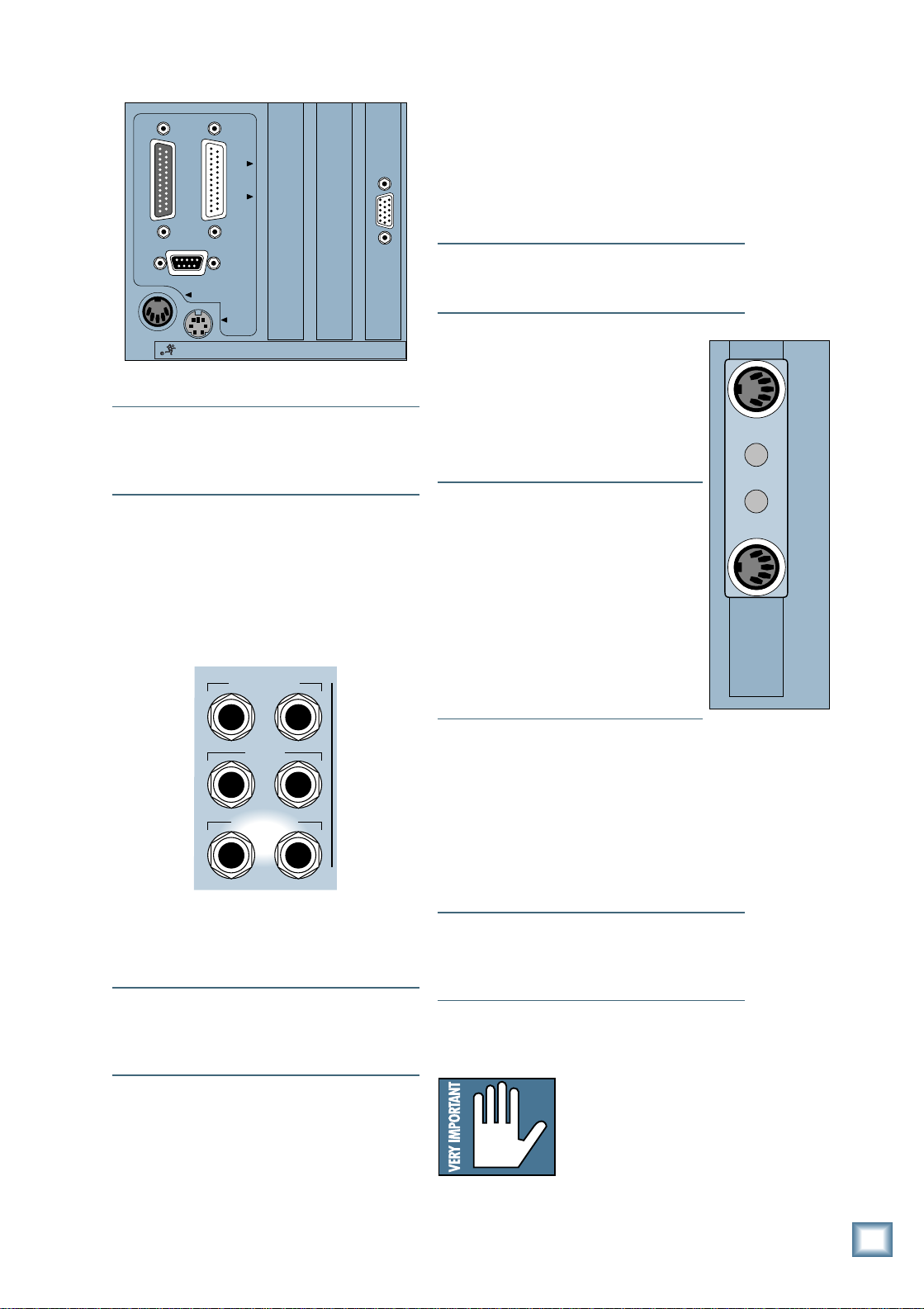
Rear Panel Description ...........................................................................................................36
Remote CPU Description ......................................................................................................... 38
Connecting a Mouse, Keyboard, and SVGA Monitor .............................................................38
Other Connections ...........................................................................................................38
Automation ....................................................................................................................39
Remote CPU Rear Panel View .................................................................................................40
T op Panel View .....................................................................................................................41
Rear Panel View ...................................................................................................................42
Mackie Designs Inc.
16220 Wood-Red Rd. NE • Woodinville, WA 98072 • USA
800/898-3211 • Outside the US: 425/487-4333
Fax: 425/487-4337 • www.mackie.com
email: sales@mackie.com
™
©1998 Mackie Designs Inc. All rights reserved. #820-075-00
1. Introduction
Now you’ve done it! You’ve just invested in
the newest generation of affordable digital
mixing consoles by Mackie Designs. Whether
or not you’ve used digital mixing consoles
before, you will be pleased by the analog feel of
our Digital 8•Bus, and by how easy it is to use.
Greg Mackie has been designing and building
analog mixers for years (since the TAPCO days
of the early ’70s), and one of the prime directives for our first digital mixing console was to
make it as easy to use as an analog mixer .
The Digital 8•Bus combines the best of both
worlds, providing an intuitive control surface
for mixing the old-fashioned way — with
faders and knobs — and providing connections
for a mouse, keyboard, and video monitor for
performing computer-oriented functions such
as file maintenance and editing. Of course, you
can perform virtually all the same mixing
functions on the video monitor as you can on
the control surface, so you have the flexibility
to choose what works best for you.
About The Quick Start Guide
This Quick Start Guide is designed to help
you get going right away . Use it, along with the
Quick Start Video, to learn the basics of setting
up and using the Digital 8•Bus. But eventually
you will have to crack open the Digital 8•Bus
Owner’ s Manual to gain a
more in-depth understanding
of what the Digital 8•Bus
can do for you.
Q u i c k S t a r t G u i d e
Unpacking
Obviously, you’ve already opened the box if
you’re reading this manual. Here are some
helpful hints on unpacking:
• The Digital 8•Bus comes in two parts, each
packed in a separate box: The Console and
the Remote CPU.
The Console
• If you haven’ t removed the Digital 8•Bus
from the packing box yet, remove the
accessory tray containing the manuals,
video, and miscellaneous literature.
• Remove the foam blocks from the ends of
the console. Just lift up on them and they’ll
come right out. The Digital 8•Bus weighs 65
pounds, so we recommend enlisting the help
of another person to assist in lifting it out of
the box. Position one person on each end of
the box and, on the count of three, lift the
console (remember: back straight, lift with
your legs!).
• Place the console on a flat surface, like the
floor next to the packing box, or a table top
large enough for the Digital 8•Bus to sit on.
• Remove the plastic bag from around the
console.
• Please save the box, the outer sleeve, and
all the foam innards. If you need to ship your
Digital 8•Bus anywhere, using the original
carton is the best way to do it.
box top
outer sleeve
left side
foam
factory fresh
console in
plastic bag
left side
lower foam
Figure 1. Unpacking the Console
Part No. 820-075-00 Rev. A 8/98
©1998 Mackie Designs Inc., All Rights Reserved. Printed in the U.S.A.
accessories
accessory tray
right side
foam
box bottom
right side
lower foam
Introduction
3
The Remote CPU
• Use a sharp knife to cut the tape on the top
of the box.
• Open the flaps to expose the Remote CPU
inside.
• Lift the Remote CPU up and out of the
packing box. The foam blocks will come
with it, and the bottom tray will lift up also.
The DC Power Cable is coiled up underneath
the bottom tray.
• Set the Remote CPU on a flat surface, like the
floor next to the packing box, or a table top.
D i g i t a l 8 • B u s
• Remove the DC Power Cable from the
bottom tray.
• Remove the foam blocks from the sides of
the Remote CPU.
• Remove the plastic bag from around the
Remote CPU, and the plastic bag from
around the DC Power Cable.
remote cpu
in plastic bag
left side
foam
connection cord
in plastic bag
Figure 2. Unpacking the Remote CPU
O
N
O
F
F
P
O
W
E
R
bottom tray
right side
foam
remote cpu
box
4
T ake a moment now to fill out the Product
Registration Card located in the back of the
Digital 8•Bus Owner’ s Manual. Mailing it in will
automatically put you on our mailing list so you
can get updated information, so do it today.
Also, write the serial numbers of your
Digital 8•Bus console and Remote CPU here
so you’ll always have them.
Console Remote CPU
Purchased at:
Date Purchased:
Introduction
2. The Basics
The Traditional Split-Console Approach
Q u i c k S t a r t G u i d e
Before we go any farther , we want to
present a concept that might help you
understand the Digital 8•Bus a little better .
Once you grasp this concept, you will begin to
understand the real beauty and power hidden
beneath the surface of this console.
The Digital 8•Bus has four layers of faders,
or fader banks, which can be individually
accessed using the select buttons in the Master
Fader/Bank Select Section. All four banks
operate simultaneously, but only one bank is
accessible at a time.
Fader Bank 1 = Channels 1–24
(1–24 MIC/LINE button)
Fader Bank 2 = Channels 25–48
(25–48 T APE button)
Fader Bank 3 = Internal Effects Returns
FX 1–16, ALT RETurns 1–8
( 49–72 EFFECTS button)
Fader Bank 4 = Virtual Groups 1–8, MIDI
Controllers 1–8, Bus 1–8 Masters
(MASTERS button)
This architecture provides a total of 56
inputs, with Fader Banks 1 and 2 providing 48
inputs, and the 8 ALT Returns in Fader Bank 3
providing another 8 inputs.
One of the primary applications that the
Digital 8•Bus was designed for is multitrack
recording (up to 24 tracks). This involves
tracking and monitoring, bouncing, overdubbing, and mixdown. You can think of Fader
Bank 1 and Fader Bank 2 as two separate
mixing consoles, where Fader Bank 1 is used
for tracking and Fader Bank 2 is used for
monitoring and mixdown.
Three Things to Keep in Mind
As you become familiar with the Digital
8•Bus, you’ll find it helpful to keep these three
questions in mind at all times:
1. What Fader Bank is selected?
2. What channel is selected?
3. What is the V-Pot assignment?
In 90% of the cases, if something isn’ t working as you expect, it is because one of these
three settings isn’ t where you intend it to be.
Tracking
The first 24 channels (Fader Bank 1) are
used for tracking; that is, to record instruments
and voices onto individual tracks of the multitrack recorders (refer to Figure 4 on the next
page). Microphones and instruments are directly
connected to the input jacks on channels 1–24,
and their signals are assigned to T ape Outputs
1–24 (and not to the L-R bus). The T ape Outputs
on the Digital 8•Bus are connected to the
inputs of the multitrack recorders where the
instruments and voices are recorded on tape
(or hard disk in the case of a Hard Disk
Recorder or DAW).
C
F
X
R
Figure 3. The Split Console
Fader Bank 1
Channels 1-24
h
a
n
n
e
l
s
1
-
2
4
C
h
a
n
n
e
l
s
2
5
-
4
8
e
t
u
r
n
1
-
1
6
;
A
L
T
R
e
t
u
r
n
1
-
8
G
r
o
u
p
s
1
-
8
;
M
I
D
I
1
-
8
;
B
u
s
1
-
8
Mic/Line
Tracking
Fader Bank 2
Channels 25-48
Monitor/Tape In
Mixdown
Fader Bank 3
FX Return 1-16
ALT Return 1-8
Fader Bank 4
Virtual Groups 1-8
M
I
D
I
C
o
n
t
r
o
l
l
Bus 1-8 Masters
e
r
s
1
-
8
The Basics
5
Channels 1-24
MIC/LINE IN
T o Tape From Tape
T ape Outs
or Bus Outs
Digital
Multitrack
Recorders
Tr acks 1-24
T APE IN
L/R MASTER
OUT
DAT Recorder
2-Tr ack
Master
CUE MIX
OUT
Channels 1-24
TRACKING HALF
D i g i t a l 8 • B u s
Fader B ank 1
Figure 4. The Split Console — Tracking
Monitoring
But wait! Of course you want to be able to
monitor the signal as you’re recording it. And
your preference is to monitor the signal actually
recorded onto the tape rather than the signal
going from the console to the tape machines,
so you can hear if there is any distortion or
unusual noise going down. Even if you’re using
all 24 channels for tracking, you’ve only used
half the channels available. There are another
24 channels available for T ape Inputs (Fader
Bank 2). This is the split-console concept.
You can connect all 24 tracks from the
multitrack recorders to the Digital 8•Bus, and
monitor them on channels 25–48, which are
assigned to the L-R bus. The tracking half is
not assigned to the L-R bus, so you can use the
monitoring half to hear the tape outputs on the
L-R bus.
Channels 25-48
MONITORING H ALF
Fader B ank 2
What’s more, all 48 channels have full DSP
capability, so you can apply EQ and effects to
the post-tape signal. And thanks to snapshot
automation, you can even create a rough mix
and store it for future use.
Overdubbing/Bouncing Tracks
The setup is the same throughout the
mixing process. No need to crawl around
behind your gear and move cables around. The
Digital 8•Bus has its own built-in patch bay to
reassign the inputs to various output
destinations.
A corollary of Murphy’s Law states that no
matter how many tracks you have available to
record, you will always need at least one more.
If you need to bounce some tracks down to
make room for the background vocal parts,
simply assign the tracks you want to bounce
Bounce down to
one or two tracks
Bus Outs
Channels 1-24
TRACKING HALF
Fader B ank 1
Figure 5. The Split Console — Bouncing Down
6
The Basics
Digital
Multitrack
Recorders
T ape T r acks In
to
Bus Outs
(This routing
is internal)
ST ART
Tr acks being
bounced
Channels 25-48
MONITORING H ALF
Fader B ank 2
CUE MIX
OUT
down to one of the Bus 1–8 Masters (Fader
Bank 4), and assign the Bus Master to any one
(for a mono mix) or two (for a stereo mix) of
the 24 T ape Outputs.
As you bounce the tracks down, you’ll
monitor the previously recorded tracks through
the monitoring half of the console.
Of course, overdubbing is simply recording
while monitoring both the live source and prerecorded tracks.
Mixdown
Mixing down is an art unto itself, but the
Digital 8•Bus gives you the tools to make the
job easier so you can concentrate more on the
art and less on the mechanics. Since the
Digital 8•Bus is fully automated, you can go
through a step-by-step process of adjusting
levels, pans, EQ, and effects. The console
remembers every move you make and plays
them back each time you make a pass, while
you add your creative touch to each and every
track. When you’re done, hit PLAY, sit back
and watch the console perform the complex
tasks you’ve programmed it to do, resulting in
a perfect mix to two-track (or multitrack for
surround-sound applications).
Signal-Flow Diagram
There is a detailed block diagram in the
Digital 8•Bus Owner’ s Manual that shows all
the signal flow and computer-controlled logic
within the console. But since this is a Quick
Start Guide, we thought it might be helpful to
have a simpler signal-flow diagram here that
shows the basic signal flow at a glance so you
don’t have to plod through the detailed drawing.
Q u i c k S t a r t G u i d e
Tracking/Routing
Analog
Inputs
CH 1-48
Optional
Digital Tape
Input
Monitoring
AES/EBU
S/PDIF
2 TRK A
2 TRK B
2 TRK C
Analog to
Digital
Converter
L/R Out
DAC
DAC
From
DSP
Control
Room
Select
Channel
Meter
Returns
Level to
Tape
Channel
Fader
Aux Send
Level
FX
Internal
Main L/R
Meter
FX
Channel
Pan
Master Aux
Send Level
Near Field
Speaker
Level
Main
Speaker
Level
Studio
Level
To Tape Outputs
Bus
Assign
Bus 1-8
AES/EBU Out
S/PDIF Out
L
Master L/R
Fader
R
Bus Master
Digital to
Analog
Converter
Digital to
Analog
Converter
Digital to
Analog
Converter
Lake Sammamish
6 miles
CR
Nearfield
Out
CR
Main
Out
Studio
Out
Main
Out
Bus 1-8
Outputs
Aux
Sends
Figure 6. Simplified Signal-Flow Diagram
Cue Mix 1
Level
Cue Mix 2
Level
Phones 1
Out
Phones 2
Out
The Basics
7
3. Tutorial Hookup —
Let’s Get It Working
This is a step-by-step guide to connect a few
things to the Digital 8•Bus and get it working.
Y ou can pop the Quick Start Video into your
VCR and follow along. You will need the
following items to proceed:
1 Electronic Keyboard
1 Stereo Power Amplifier
1 pair of Monitor Speakers (you can
substitute a pair of powered monitors for the
D i g i t a l 8 • B u s
power amplifier/monitor speakers combo)
1 8-track recorder (or multitrack recorder of
your choice)
1 AIO•8 or DIO•8 (T ape I/O card)
Miscellaneous cables
1 cup of coffee (or alternate beverage of your
choice)
and provide additional support at the rear of
the unit.
The connecting cables can reach up to 15
feet, so the Remote CPU must be within 15
feet of the console. If you’re going to use the
optional keyboard/monitor/mouse interface
devices, you’ll want to locate the Remote
CPU close enough for your equipment to
reach your work surface.
3. Connect the DC power cable between the
Remote CPU and the console. Rotate the
outer sleeve of the connector clockwise until
the sleeve is snug and finger-tight.
4. Connect the data cable between the Remote
CPU and the console. Rotate the thumbscrews on each connector clockwise until
they are finger tight.
5. Make sure the POWER switch on the
Remote CPU is off.
6. Connect the detachable linecord to the
Remote CPU.
Hookup Stuff
First, connect the Remote CPU to the console.
1. Place the console on your work surface.
2. Place the Remote CPU in some convenient
location nearby. It’ s rack-mountable, so you
can put it in a rack if you so desire.
Caution: The Remote CPU
weighs 42 pounds, so we
recommend that if you
mount it in a rack, you place
it at the bottom of the rack
MIDI Interface
Multitrack Recor der
TAPE 1-8 TAPE 9-16 TAPE 17-24
1
IN
OUT
2
S/PDIF
WARNING:
SHUT OFF REMOTE POWER SUPPLY BEFORE CONNECTING
OR DISCONNECTING POWER SUPPLY CABLE FROM CONSOLE
POWER
SUPPLY
WARNING:
TO REDUCE THE RISK OF FIRE OR ELECTRIC SHOCK, DO NOT
CAUTION
EXPOSE THIS EQUIPMENT TO RAIN OR MOISTURE. DO NOT REMOVE COVER.
NO USER SERVICEABLE PARTS INSIDE. REFER SERVICING TO QUALIFIED PERSONNEL.
RISK OF ELECTRIC SHOCK
DO NOT OPEN
AVIS:
RISQUE DE CHOC ÉLECTRIQUE — NE PAS OUVRIR
UTILISE UN FUSIBLE DE RECHANGE DE MÊME TYPE.
REPLACE WITH THE SAME TYPE FUSE AND RATING.
DEBRANCHER AVANT DE REMPLACER LE FUSIBLE
DISCONNECT SUPPLY CORD BEFORE CHANGING FUSE
WARNING: SHUT OFF POWER TO UNIT BEFORE INSTALLING OR REMOVING CARDS!
56
INPUT72 CHANNEL
CONSOLE
DATA
SERIAL NUMBER
DIGITAL MIXER
A B C D
MANUFACTURING DATE
DIGITAL EFFECTS CARDS DIGITAL I/O SYNC ALT I/O TAPE IN/OUTS
DIGITAL I/O
DIGITAL I/O
IN
OUT
AES/EBU
ANALOG I/O
BUS OUT 1-8
&
SURROUND OUT
L
ANALOG IN ANALOG OUT
R
MASTER OUT
LINE INPUTS
(BAL/UNBAL)
16
172418
23
MASTER OUT
LR
MAIN
LR
NEAR FIELD
LR
THIS DEVICE COMPLIES WITH PART 15 OF THE FCC RULES. OPERATION IS SUBJECT TO THE FOLLOWING TWO CONDITIONS:
1) THIS DEVICE MAY NOT CAUSE HARMFUL INTERFERENCE AND
2) THIS DEVICE MUST ACCEPT ANY INTERFERENCE RECEIVED THAT MAY CAUSE UNDESIRED OPERATION
PHONES 1
2 TRACK IN A
LR
CR
2 TRACK IN B
LR
CR
2 TRACK IN C
PUNCH I/O
LR
MACKIE DESIGNS
Next, connect the keyboard, mouse, and video
monitor.
Note: These connections are optional, but we
recommend using them to get the most from
your new Digital 8•Bus console.
1. Plug a PC-compatible keyboard into the KEYBOARD port on the back of the Remote CPU.
2. Plug a PS/2-compatible mouse into the
MOUSE port on the back of the Remote CPU.
3. Plug an SVGA video monitor into the VIDEO
port on the back of the Remote CPU.
11
12
13
+48V
+48V
PH
PH
MIC MIC10MIC9MIC8MIC7MIC6MIC5MIC4MIC3MIC2MIC1MIC
19
2014211522
STUDIO OUT
LR
LINE IN
LINE IN
PHONES 2
INSERT
INSERT
TALKBACK
AUX11AUX
12
+48V
+48V
+48V
PH
PH
PH
LINE IN
LINE IN
LINE IN
INSERT
INSERT
INSERT
AUX8AUX9AUX
10
CONCEIVED, DESIGNED, AND MANUFACTURED BY MACKIE DESIGNS INC • WOODINVILLE • WA • USA • MADE IN USA • FABRIQUE AU USA • COPYRIGHT ©1997 •
THE FOLLOWING ARE TRADEMARKS OR REGISTERED TRADEMARKS OF MACKIE DESIGN INC.: "MACKIE", "DIGITAL SYSTEMS", D8B AND THE "RUNNING MAN" FIGURE •
+48V
+48V
+48V
PH
PH
PH
LINE IN
LINE IN
LINE IN
INSERT
INSERT
INSERT
7
AUX OUT
(BAL/UNBAL)
+48V
+48V
PH
LINE IN
INSERT
+48V
+48V
PH
PH
PH
LINE IN
LINE IN
LINE IN
INSERT
INSERT
INSERT
AUX1AUX2AUX3AUX4AUX5AUX6AUX
PATENTS PENDING
DC Power
Cable
MANUFACTURING DATE
MACKIE DESIGNS
THIS DEVICE COMPLIES WITH PART 15 OF THE FCC RULES. OPERATION IS SUBJECT TO
THE FOLLOWING TWO CONDITIONS: 1) THIS DEVICE MAY NOT CAUSE HARMFUL
INTERFERENCE AND 2) THIS DEVICE MUST ACCEPT ANY INTERFERENCE RECEIVED THAT
MAY CAUSE UNDESIRED OPERATION
120V
60Hz, 2.8A
120/230V
1.0/0.5A
SERIAL NUMBER
Figure 7. Quick Start Hookup
8
Tutorial Hookup — Let’s Get It Working
Data Cable
VIDEO
PARALLEL
CONSOLE DATA
SERIAL
KEYBOARD
MOUSE
CONCEIVED, DESIGNED, AND MANUFACTURED BY MACKIE DESIGNS INC • WOODINVILLE • WA • USA • MADE IN USA • FABRIQUE AU USA • COPYRIGHT ©1997 •
THE FOLLOWING ARE TRADEMARKS OR REGISTERED TRADEMARKS OF MACKIE DESIGN INC.: "MACKIE", "DIGITAL SYSTEMS", D8B AND THE "RUNNING MAN" FIGURE •
MIDI In
MIDI Out
CONSOLE DATA
PARALLEL
SERIAL
KEYBOARD
CONCEIVED, DESIGNED, AND MANUFACTURED BY MACKIE DESIGNS INC • WOODINVILLE • WA • USA •
THE FOLLOWING ARE TRADEMARKS OR REGISTERED TRADEMARKS OF MACKIE DESIGN INC.: "MACKIE", "D
VIDEO
MOUSE
Note: The video monitor must be a multi-sync
monitor or , if not, capable of at least a 72Hz
scan rate. We recommend using a 17-inch or
larger monitor for best results.
Now connect the audio inputs and outputs to
the console.
1. Using standard “guitar cord”-type cables
with 1/4" phone plugs, connect the Left and
Right CR NEAR FIELD outputs on the rear
panel of the Digital 8•Bus to the left and
right inputs of the power amplifier .
MASTER OUT
LR
If you are using the digital T ape I/O card,
refer to the Digital 8•Bus Owner’s Manual
(Appendix F) for connection information.
The connection on the other end of the cable
depends on your recording deck. It could be
any number of flavors, including Elco, 1/4"
phone plug, RCA phono plug, XLR, 25-pin
D-Sub, 3/4" garden hose, etc.
Note: If you’re using a patch bay , place it
between the Digital 8•Bus and your tape
recorder .
Connections for MIDI
1. On the back of the Remote CPU, plug
the supplied dual output MIDI jack
adapter into the 9-pin D-Sub MIDI
connector . The output jack has standard
5-pin MIDI IN and OUT sockets on it.
Connect these to the MIDI IN and
OUT connectors on your recorder .
Note: Most recorders require a MIDI
interface box to go between an external
MIDI control device such as the Digital
8•Bus, and its own MIDI I/O. Check
your recorder’s manual for more
information.
Note: If you’re using more than one 8track recorder , you may need to match
your device ID with that of the Digital
8•Bus’ software. Please consult the
Digital 8•Bus Owner’ s Manual and your
recorder’s manual for proper settings.
Q u i c k S t a r t G u i d e
MIDI
OUT
MIDI
IN
CR
MAIN
LR
CR
NEAR FIELD
LR
2. Using heavy-gauge speaker wire appropriate
for the power of the amplifier , connect the
left and right outputs of the power amplifier
to the speaker inputs.
Note: If you’re using powered monitors,
connect the Left and Right CR NEARFIELD
outputs directly to the line inputs on the
powered monitors.
3. To connect a recording deck to the Digital
8•Bus, it is necessary to have at least one of
the optional T ape I/O cards installed. For this
example, we’ll use an analog T ape I/O card.
This card has two 25-pin D-Sub connectors
for connecting the analog T ape I/O signals to
your tape deck.
Optional Refreshments
1. Take a sip of coffee.
Power-Up
• Make sure the POWER switch on the
Remote CPU is off. Now plug the linecord
into an AC outlet properly configured for
your model.
Note: The Remote CPU should be treated as
you would any computer . We recommend that
you use a UPS (Uninterruptible Power Supply)
and a surge protector on the AC line.
• Leave the POWER switch off while
connecting the peripheral equipment to the
console.
Caution: Never connect or
disconnect anything except
microphone or line-level
inputs while the console is
powered up.
Tutorial Hookup — Let’s Get It Working
9
T urn on the power switch on the front panel
of the Remote CPU, then turn on the power to
all your peripheral equipment. The Digital
8•Bus takes a few moments to load the Mackie
Real Time OS (Operating System) and initialize
the DSPs. When the Vacuum Fluorescent Display
in the Fat Channel Section indicates EQ settings
for channel 1, the console is ready to use.
Now we’ll look at some of the basics like
setting up system options, creating a session,
and creating a default snapshot.
Downloading Plug-Ins
Before beginning a session, you can
download the effects algorithms of your choice
to the internal FX cards.
Loading Effects with Console Controls:
• Press the PLUG INS button in the Setup
Section.
SETUP
SAVE
SAVE AS... NEW
LOAD
D i g i t a l 8 • B u s
Start-up
System Options
The system options are found in the
General Setup menu. You should confirm
that all the system settings are correct for
your configuration and application. Go here
to set the language, surround mode, MIDI
settings, Auto Save settings, and Aux
Pre/Post Fader setting.
Note: If you’re using a digital T ape I/O card,
you’ll need to do some additional software
setups. See the section called “Configuring
Digital I/O” in Chapter 3 of the Digital
8•Bus Owner’s Manual.
• Press the GENERAL button in the Setup
Section.
SAVE
GROUP
SAVE AS... NEW
GENERAL PLUG INS DIGITAL I/O
SETUP
LOAD
GROUP
GENERAL PLUG INS DIGITAL I/O
A menu of options appears in the Fat
Channel Display.
D8B
56 INPUT / 72 CHANNEL DIGITAL MIXER
Pick a Card to setup: (PLUGIN SETUP)
Card A Card B Card C Card D
• Press the SELECT button below the card
you want to configure. The basic console
ships with one FX card installed (CARD A).
Y ou can purchase and install up to three more
cards to provide more simultaneous effects.
D8B
56 INPUT / 72 CHANNEL DIGITAL MIXER
MackieFX (PLUGIN-CARD1)
<< >> Cancel Transmit
• Use the SELECT buttons below the arrows
in the Fat Channel Display to scan through
available Plug-Ins. When the Plug-In you
want appears, press the SELECT button
below Transmit to download the algorithm
to the selected FX Card.
10
A menu of options appears in the Fat
Channel Display.
D8B
56 INPUT / 72 CHANNEL DIGITAL MIXER
(GENERAL SETUP Pg1 ->)
Language Surround MIDI AutoSave
• Press the SELECT button below the option
you want to change and a new menu
appears related to that specific option.
• In general, use the SELECT buttons to scan
through available options, and use the V-Pots
to adjust parameters (where applicable). Use
the PREVIOUS and NEXT buttons to page
over to more options (if available).
Refer to Chapter 3 (“Start-Up”) in the
Digital 8•Bus Owner’s Manual for more details
on each option.
Tutorial Hookup — Let’s Get It Working
Loading Effects with Mouse and Monitor:
• Click on the “Setup” button in the lower
menu bar . The Setup dialog box window
appears on the screen.
• Click on “Plug-Ins” on the left side of the
setup window .
• Click on the box next to CARD A and select
Mackie FX from the drop-down menu. As
soon as it’ s selected, the algorithm is
downloaded to the FX Card.
Getting Sound Out
Now that you have set all the options the
way you want them, we can make a sample
recording and see how the Digital 8•Bus
actually works.
• First, connect a keyboard to channels 3 and
4 line inputs. Channels 3 and 4 MIC buttons
should be in the UP position. Turn the faders
all the way down, including the MASTER
L-R fader .
• Select Fader Bank 1 (MIC/LINE 1–24).
MASTERS
1-24
MIC/LINE
(TRACK) (MONITOR)
SHIFT
25-48
TAPE IN
• Make sure the MASTER L-R button and the
NEAR FIELD button are lit in the Control
Room Section.
CONTROL ROOM
2 TRACK A
2 TRACK B
2 TRACK C
NEAR FIELD
MONO
SPEAKERS
DIGITAL IN 1
DIGITAL IN 2
MASTER
L-R
MAIN
TRIM
0
-
20dB
REC/RDY
ASSIGN
WRITE
12
MIC
Q u i c k S t a r t G u i d e
N
E
I
L
C
I
M
60
+40dB
49-72
EFFECTS
BANK SELECT
• Set the source — in this case, the keyboard
— for unity output level, and watch the
channel meters as you adjust the TRIM knob.
Note: The channel meters are pre-fader , so you
don’ t need to adjust the faders for this operation.
• Set the TRIM for a meter indication around
–15 (the fat bar on the meter). Under no
circumstances should the levels go to the top
OL on the meter or you will experience digital
clipping, which is a most unpleasant sound.
12
36
OL
Sounds Ugly
2
4
7
10
Just Right
15
20
25
30
35
40
Too Low
50
• Bring up the faders on channels 3 and 4
while the keyboard is providing an input
signal. Set the faders at the unity gain mark.
• Slowly bring up the MASTER L-R fader . You
may or may not hear sound, depending on
the settings in the Control Room Section.
Set it at or near the unity gain mark.
SPEAKER LEVEL
DIM
TALKBA CK
• While playing the keyboard, slowly rotate
the SPEAKER LEVEL V-Pot in the Control
Room Section and set it at a comfortable
listening level.
Preparing to Record
Now that input levels are set, we want to
monitor the returns from the recording deck
rather than the channel inputs. T o avoid double
monitoring, turn off the L-R bus assignment on
channels 3 and 4.
• With Fader Bank 1 (MIC/LINE 1–24)
selected, press the MASTER L-R button in
the Bus Assignment Section.
ASSIGNMENT
ASSIGN ASSIGN
BUS 1
ASSIGN ASSIGN
BUS 3 BUS 4
ASSIGN ASSIGN
BUS 5
ASSIGN ASSIGN
BUS 7
ASSIGN ASSIGN
L-R
• T urn off the ASSIGN buttons on channels 3
and 4.
BUS 2
BUS 6
BUS 8
ROUTE TO
TAPE
MIDI 4
FX 12
dB
10
5
U
5
10
20
30
40
50
60
12
36
SELECT
SOLO
MUTE
12
36
Tutorial Hookup — Let’s Get It Working
11
SHIFT
MASTERS
1-24
25-48
49-72
(TRACK) (MONITOR)
BANK SELECT
EFFECTS
MIC/LINE
TAPE IN
SHIFT
MASTERS
1-24
25-48
49-72
(TRACK) (MONITOR)
BANK SELECT
EFFECTS
MIC/LINE
TAPE IN
TRIM
L
Assigning Channels 3 and 4 to T racks 3 and 4.
• Select Fader Bank 2 (T APE IN 25–48).
• Make sure Fader Bank 1 is selected (1–24
MIC/LINE).
N
E
I
C
I
M
60
0
+40dB
-
20dB
12
MIC
D i g i t a l 8 • B u s
REC/RDY
ASSIGN
WRITE
• Press the ROUTE TO T APE button in the
MASTERS
1-24
MIC/LINE
(TRACK) (MONITOR)
Bus Assignment Section.
ASSIGNMENT
ASSIGN ASSIGN
12
36
SELECT
SOLO
MUTE
BUS 1
ASSIGN ASSIGN
BUS 3 BUS 4
ASSIGN ASSIGN
BUS 5
ASSIGN ASSIGN
BUS 7
ASSIGN ASSIGN
L-R
49-72
EFFECTS
BANK SELECT
SHIFT
25-48
TAPE IN
BUS 2
BUS 6
BUS 8
ROUTE TO
TAPE
• Press the ASSIGN buttons on channels 27
and 28 to assign them to the Left/Right bus.
Now arm tracks 3 and 4:
• Select Fader Bank 1 (MIC/LINE 1–24).
10
5
U
5
10
20
30
40
50
60
MIDI 4
FX 12
dB
12
36
• Press the SELECT button on channel 3.
• Press the ASSIGN button on channel 3.
Channel 3 is now assigned to Tape Out 3, which
goes to T rack 3 on your multitrack recorder.
• Press the SELECT button on channel 4.
• Press the ASSIGN button on channel 4.
Channel 4 is now assigned to Tape Out 4, which
goes to T rack 4 on your multitrack recorder.
Next, assign channels 27 and 28 (which are
T ape Out 3 and 4 from the multitrack) to the
Left/Right Bus:
• Press the MASTER L-R button in the Bus
Assignment Section.
ASSIGNMENT
ASSIGN ASSIGN
BUS 1
ASSIGN ASSIGN
BUS 3 BUS 4
ASSIGN ASSIGN
BUS 5
ASSIGN ASSIGN
BUS 7
ASSIGN ASSIGN
L-R
BUS 2
BUS 6
BUS 8
ROUTE TO
TAPE
• Press the REC/RDY buttons on channels 3
and 4 to arm the tracks for recording, or
press the corresponding buttons on the tape
recorder .
• Start playing the keyboard. The meter
indications on the tape recorder should be
equivalent to the meter indications on the
console.
Important: The channel
faders do NOT set output
levels to the recorder . If the
meter indications on the
recorder are too high or too
low , you can adjust the
levels by pressing the LEVEL TO T APE
button in the V-Pot Select Section. The
channel V-Pots become level controls for the
tape outputs. Adjust the V-Pots so the meter
indication on the tape recorder is at its
recommended level.
Next, get signal from the tape back to the console
and out the Control Room speakers (or
headphones):
• Put your multitrack recorder into Record/
Pause mode. This will allow the signal to
pass through the recorder and back to the
console.
12
Tutorial Hookup — Let’s Get It Working
 Loading...