

Luxman L-590-AX Owners Manual

,17(*5$7('$03/,),(5
/$;
Owner`s Manual

Contents
Precautions ············································································································· 1
Features of This Unit································································································ 2
Names and Functions······························································································ 4
Connections ·········································································································· 12
Operations ············································································································· 16
How to Use Remote Control·················································································· 18
Block Diagram······································································································· 20
Specifications ········································································································ 21
Before Asking for Repair Services·········································································· 22
Precautions
INTEGRATED AMPLIFIER L-590AX
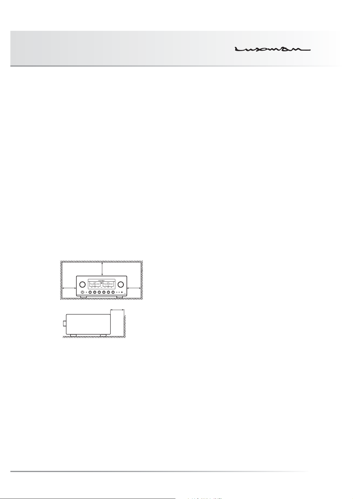
Installation place
This unit shall be installed in a well-ventilated and effectively
heat-released place because this unit is an A-class amplifier
and generates considerable heat.
Especially, installation of this unit where direct sunlight is
present, where the temperature rises excessively high such
as close to a heater, or where it is humid or dusty may cause
a malfunction even if heat is efficiently released. Therefore, do
not install this unit in such places.
Ventilation holes
The ventilation holes on the top and bottom boards of this
product must not be blocked because this unit is an A-class
amplifier and generates considerable heat. If the amplifier is
installed on a rack or the like, secure ample space for cooling
and leave the door open. Do not pile up other things on the
amplifier and never put articles on it. Failure to observe this
may cause a malfunction.
Note:
For heat dispersal, do not install this equipment in a confined
space such as a book case or similar unit.
* Note
**
*
Cautions in connecting speakers
When making speaker system connections, exercise extra
care not to short-circuit between ! and @ of the speaker ter-
minals and speaker input terminals of this unit. If a large signal
is applied to the amplifier with its circuit left short-circuited, a
large current may be passed through the output circuit and
cause a malfunction.
The sound is not generated shortly after
the power supply is turned on.
This amplifier is equipped with a time muting circuit in order to
separate the output circuit. Therefore, no sound is generated
shortly after the power supply is turned on.
If the volume control is moved to a high sound level before
the time muting circuit is canceled, a large sound is suddenly
generated. Please be advised that the volume control shall be
set to a low level at first and adjusted after sound comes out
of the speakers.
Protection circuit
This product is equipped with a protection circuit that is ac-
tivated upon detection of overcurrent, abnormally high tem-
perature, and DC drift to protect the amplifier and speakers.
When the protection circuit is activated, the output to the
speaker terminal is shut off and the standby indicator blinks to
show that this unit is in the muting state. If the protection cir-
cuit is frequently activated even when disconnecting the pow-
er plug from the wall outlet and turning on the power again
after a lapse of a certain time, please consult your dealer.
Wall
Precautions in connecting with other
components
When connecting this unit to input devices such as a CD
player, an SACD player, a tuner, and a recorder, be sure to
turn off the power of this unit and all other connected devices.
Failure to observe this may generate a strong noise resulting
in speaker damage or cause a malfunction.
The pin-plug to be inserted in each input terminal of this unit
shall be pushed in firmly. If the grounding terminal is inad-
equately connected, noises including hum may be generated,
resulting in an adverse S/N ratio.
Batteries
Caution:
Batteries used for remote controller shall not be exposed to
excessive heat such as sunshine, fire or the like.
Repair and adjustment
When repairs or adjustments are needed, please ask the
dealer where you bought the unit.
Cleaning
For cleaning, use a piece of soft cloth to wipe the unit such as
cleaning cloth available on the market. If the unit has become
very dirty, remove the dirt with soft cloth absorbing a small
amount of neutral detergent, and then wipe the unit with dry
cloth. Do not use a solvent like benzine or thinner because
such a substance can often damage the exterior.
1

Features of This Unit
LECUA-WM - LUXMAN Electric Controlled
Ultimate Attenuator - Waiting Matrix
Application of the system to obtain attenuation by combin-
ing 2 fixed resistances connected to this product series has
improved efficiency of the LECUA1000 attenuator used in our
flagship model, C-1000f.
The shortest signaling route has been achieved by the in-
tegrated amplifier circuit thanks to the 3D structure of the
mounting boards.
Controlling LECUA-WM to the level equal to the volume po-
sition detected by a microprocessor has achieved the op-
eration feeling similar to our conventional sliding-type volume
controls.
ODNF - Only Distortion Negative Feedback -
The amplification feedback circuit that has acquired the high-
speed primary slew rate and ultra-high bandwidth by feeding
back only distortion components generated during amplifica-
tion to maintain the pure sound quality of the main-amplifier
that is almost non-feedback.
The newest version, 3.0A, has achieved the low impedance
and high S/N ratio of the transmission circuit by parallelization
of the first and second stages of the amplifier circuit.
In addition, the input stages of the error detection circuit are
parallelized to moderate the frequency characteristic and
noise.
Parallel speaker relays
This unit is equipped with large type of 2 parallel speaker re-
lays with a low resistance value to reduce the impedance of
the speaker output lines.
Beeline construction
Newly designed beeline construction composes the audio
input signal via the optimally shortest route to the speaker
output.
Selector switch IC
Selector switch IC with high sound quality, which is used in
the top-end control amplifier, C-1000f, improves the separa-
tion and crosstalk performances.
Schottky barrier diode
Application of schottky barrier diode manufactured by Nihon
Inter Electronics Corporation that has less switching noises
and higher conversion efficiency to the DC voltage for the
power supply rectifier circuit.
LUXMAN’s original OFC wires
Our original OFC wires are used in the internal wiring to
achieve smooth signal transmission thanks to the spiral wrap
shielding on each core and the non-plating process on the
core wire.
3 parallel push-pull output stages
3 parallel push-pull structure of bipolar transistor.
Pure class A rated output 30W+30W (8Ω).
High-inertia power supply
High-inertia electronic circuit that combines a large-capacity
EI-core-type power transformer with customizable 10,000μF
× 4 capacitor blocks.
2
Round pattern board
After careful consideration of delicate audio signal flow, a
round pattern board has been applied to achieve smooth sig-
nal transmission.

INTEGRATED AMPLIFIER L-590AX
Phono amplifier
This unit is equipped with a phono amplifier that is compat-
ible with the MM/MC cartridge to achieve analog record re-
production in a high-grade level without adding a dedicated
phono amplifier.
Separate function
This unit is equipped with a separate switch to separate the
pre-amplifier and power-amplifier each other that enables the
bi-amp connection adding a power-amplifier and the coexis-
tence with an AV system.
Loopless chassis structure
This unit consists of the independent construction of a
loopless chassis to eliminate increased ground impedance
caused by chassis current.
18 mm pitch RCA terminal
Introduction of 18 mm pitch all RCA input/output terminals
allows even a high-performance line cable with large plug to
be connected.
Large type of speaker terminals
Speaker terminals (A and B systems) of inline layout (with
same characteristics for right and left), which is compatible
with Y lugs and banana plugs to enable easy connection with
extra-thick speaker cables.
New standard size
This unit has been manufactured based on LUXMAN's new
standard size (440mm wide, common with a series of sepa-
rate amplifiers and a series of SACD players.
Cast-iron insulator
This unit is equipped with gradation cast-iron insulators that
cuts out unnecessary external vibration and strongly supports
the weight of this unit.
Headphone output terminal
This terminal allows you to casually enjoy sound even at mid-
night.
AC inlet
This inlet enables the connection with an external power ca-
ble.
Hairline finish for the top board
Application of surface treatments such as blasted white for
the main unit and sophisticated hairline finish for the top
board.
Needle-type meter
This unit is equipped with needle-type meters lighted with
LED, which improves the visibility in the room where the unit
will be installed.
Ventilation
For enhancing the heat radiation efficiency of this unit, ventila-
tion holes on the top board are wider than our conventional
models.
Remote control encased in aluminum
The high-grade remote control, which is encased in alumi-
num, can control applicable CD/SACD players.
3
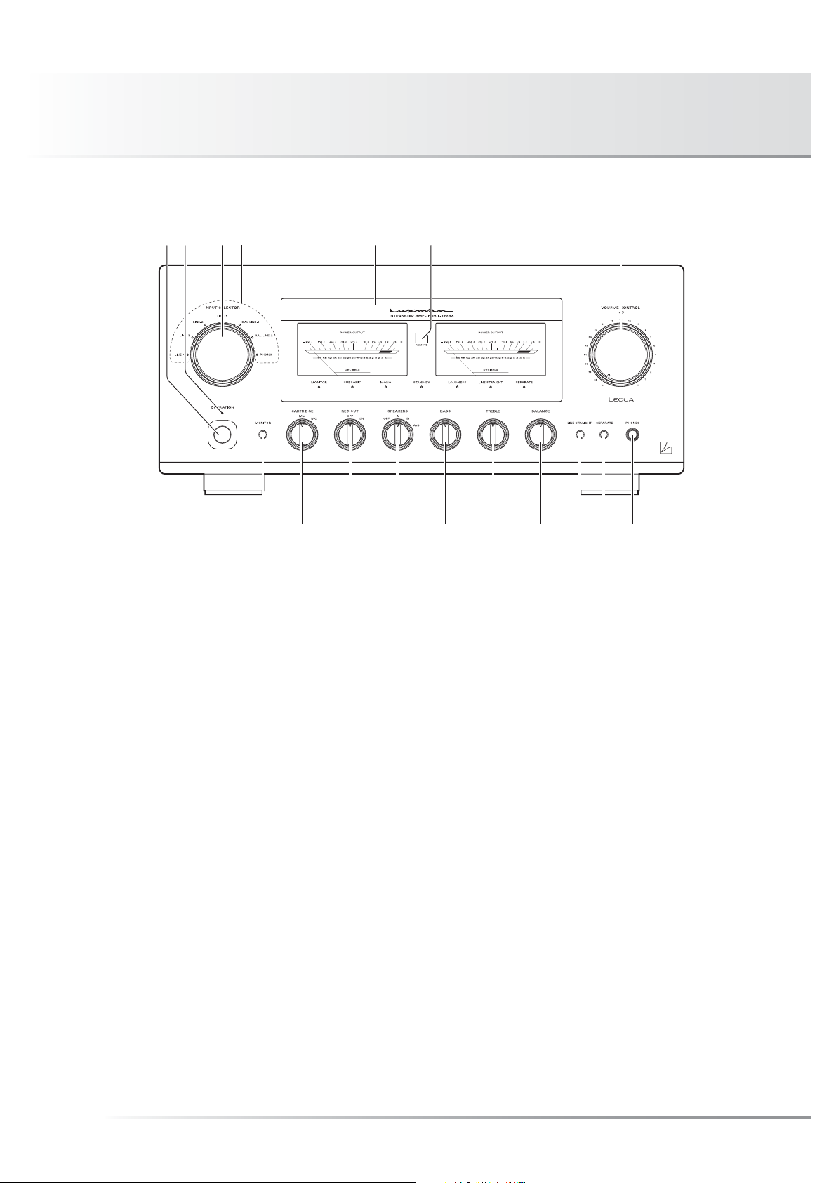
Names and Functions
Front panel
56
712 43
1. Operation switch (OPERATION)
Toggles the power on and off.
When wiring or connection is performed, be sure to turn off
this switch.
2. Operation indicator (OPERATION)
Blinks in the time of muting mode when the operation
switch is turned on and lights up when the operation state
is activated afterward. This indicator blinks when the unit is
in the muting mode or when the volume is adjusted with the
remote control.
891011121314151617
3. Input selector (INPUT SELECTOR)
Selects an input device from the devices such as a CD play-
er, an SACD player and a tuner connected to each input
terminal.
The input selector has 7 positions consisting of LINE-4,
LINE-3, LINE-2, LINE-1, BAL LINE-1, BAL LINE-2, and
PHONO from left to right that correspond to each input ter-
minal on the rear panel. The knob is rotated to light the input
indicator of the input device to be selected.
4. Input indicator
Lights up at the input device to be selected with the input
selector or remote control.
4

INTEGRATED AMPLIFIER L-590AX
5. Display
Displays the operation status of this unit.
This display is composed of 7 indicators and 2 power me-
ters.
6. Remote control infrared receiver
(REMOTE)
This is a sensor to receive signals from the accessory re-
mote control.
7. Volume control (VOLUME CONTROL)
Adjusts the sound volume. Sound is not generated when
this control is rotated counterclockwise to the end, and
then, the sound volume gradually becomes higher when the
control is slowly rotated clockwise.
8. Headphone jack (PHONES)
Insert the headphone plug into this output jack. Even when
the plug is inserted, signals to the speaker output terminal
are not interrupted. Accordingly, to listen to sound with only
use of headphones, set the speaker selector to off.
9. Separate switch (SEPARATE)
Separates the pre-amplifier and main-amplifier each other.
off : Uses this unit as a normal pre-main amplifier.
(separate
indicator off)
on : Feeds external signals from the MAIN IN termi-
(separate
indicator on)
Every pressing of this switch toggles the separate on and
•
off.
The separate indicator lights up when the separate switch
is on.
When the separate switch is set to on, the volume control of
this unit cannot adjust the volume of the speakers connected
to this unit. Volume adjustment shall be performed at the
input device side such as the control amplifier connected to
the MAIN IN terminal.
Entry of direct output into the MAIN IN terminal from a CD
player or other devices that cannot adjust sound volume
constantly provides a full power state and accordingly results
in the risk of speaker damage.
For such input devices, be sure to use a control amplifier
equipped with the sound volume adjustment function as
a relay, generate sound through the speakers with volume
lowered, and adjust the volume to your favorite level.
When arranging the wiring, be sure to turn off the power of
this unit.
nal on the rear panel to the main-amplifier sec-
tion.
5

Names and Functions
Front panel
56
712 43
10. Line straight switch (LINE STRAIGHT)
Enhances the purity of the sound quality by bypassing the
balance control circuit, tone control circuit, or the like.
off : Line straight off/bypass off
(line straight
indicator off)
on : Line straight on/bypass on
(line straight
indicator on)
• Every pressing of this switch toggles the line straight on
and off.
The line straight indicator lights up when the line straight
switch is on.
When the line straight switch is set to on, the balance control,
tone control, subsonic, monaural and loudness cannot be
adjusted and the mode selector does not function.
891011121314151617
11. Balance control (BALANCE)
Adjusts the balance of sound volume between right and left
channels.
Rotating this switch counterclockwise causes the left sound
volume to be enhanced, and rotating the switch clockwise
causes the right sound volume to be enhanced.
This switch shall be set to the center position under normal
conditions, and rotated to make adjustment if necessary.
When the line straight switch is set to on, this switch does
not function.
12. Tone control for treble (TREBLE)
Controls the frequency characteristics in the high-frequency
range.
When this switch is set to the center position, flat frequency
characteristic is obtained. Rotating the switch clockwise
causes the high-frequency range to be enhanced, and
rotating the switch counterclockwise causes the high-fre-
quency range to be attenuated.
When the line straight switch is set to on, this switch does
not function.
6

INTEGRATED AMPLIFIER L-590AX
13. Tone control for bass (BASS)
Controls the frequency characteristics in the low-frequency
range.
When this switch is set to the center position, flat frequency
characteristic is obtained. Rotating the switch clockwise
causes the low-frequency range to be enhanced, and rotat-
ing the switch counterclockwise causes the low-frequency
range to be attenuated.
When the line straight switch is set to on, this switch does
not function.
14. Speaker selector (SPEAKERS)
Selects either of 2 speaker systems, A or B, located at the
rear panel.
OFF: Activates only headphones. No sound is gener-
ated from any speakers.
A: Selects the A system speaker terminal.
(center)
B: Selects the B system speaker terminal.
A+B: Simultaneously activates both A and B system
speakers. When both speaker terminals are si-
multaneously used, select speakers with imped-
ance of 8 ohms or more because both output
terminals are connected in parallel.
16. Cartridge selector (CARTRIDGE)
Changes the gain level of the equalizer amplifier (amplifier
circuit required to play an analog record).
MC: Selects an MC (moving coil) type cartridge of low
output voltage.
Be aware that the sound volume becomes higher
and unbalanced sound without high frequencies
is generated owing to the impedance when “MC”
is selected during use of the MM type cartridge.
MM: Selects an MM (moving magnet) type cartridge of
high output voltage.
17. Monitor switch (MONITOR)
Toggles between use and nonuse of the monitor input ter-
minals (MONITOR) on the rear panel.
on : Enables to reproduce the data from the recorder.
(monitor
indicator off)
off : Enables to reproduce the data from the source
(monitor i
indicator on)
• Every pressing of this switch toggles the monitor on and
off.
The monitor indicator lights up when the monitor switch
is on.
selected with the input selector.
15. Recording switch (REC OUT)
Sends recording signals to the recorder connected to this
unit.
OFF: Does not send recording signals to the recorder
output terminals on the rear panel.
When not using the recorder, set the recording
switch to this position.
ON: Selects an input source to be recorded with the
input selector and sends recording signals to the
recorder connected the recorder output terminals
of this unit.
7
 Loading...