

Page 1

INTEGRATED AMPLIFIER
L-505uX
Page 2

2
Contents
Precautions..........................................................................................................................1
Features of This Unit ...........................................................................................................2
Names and Functions..........................................................................................................4
Connections.......................................................................................................................10
Operations .........................................................................................................................14
How to Use Remote Control ..............................................................................................16
Block Diagram ...................................................................................................................18
Specications ....................................................................................................................19
Before Asking for Repair Services .....................................................................................20
Page 3
1
NTEGRATED AMPL FIER L-505uX
Precautions
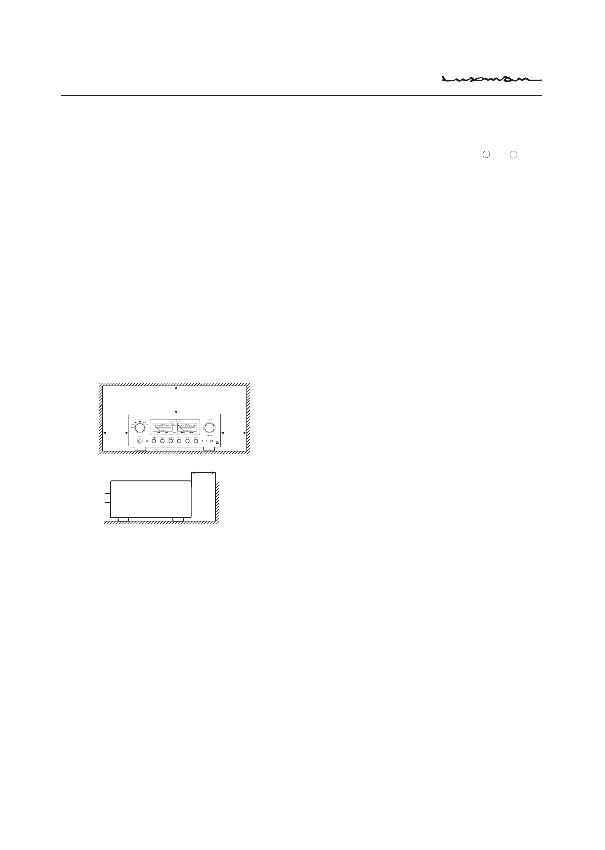
Installation place
This unit shall be installed in a well-ventilated and
effectively heat-released place.
Espe
cially, installation of this unit where direct
sunlight is present, where the temperature rises
excessively high such as close to a heater, or where
it is humid or dusty may cause a malfunction even if
heat is efciently released. Therefore, do not install
this unit in such places.
Ventilation holes
If the amplier is installed on a rack or the like,secure
ample space for cooling and leave the door open. Do
not pile up other things on the amplier and never put
articles on it. This can cause malfunctioning.
Note:
For heat dispersal,do not install this equipment in a
conned space such as a book case or similar unit.
* Note
* *
*
Wa
Cautions in connecting speakers
When making speaker system connections, exercise
extra care not to short-circuit between
speaker terminals and speaker input terminals of this
unit. If a large signal is applied to the amplier with its
circuit left short-circuited, a large current may be passed
through the output circuit and cause a malfunction.
+
and - of the
The sound is not generated shortly after
the power supply is turned on.
This amplier is equipped with a time muting circuit in
order to separate the output circuit. Therefore, no sound
is generated shortly after the power supply is turned on.
If
the volume control
before the time muting circuit is canceled, a large
sound is suddenly generated. Please be advised that
the volume control shall be set to a low level at rst
and adjusted after sound comes out of the speakers.
is moved to a high sound level
Protection circuit
This product is equipped with a protection circuit that
is activated upon detection of overcurrent, abnormally
high temperature, and DC drift to protect the
amplier and speakers. When the protection circuit is
activated, the output to the speaker terminal is shut
off and the standby indicator blinks to show that this
unit is in the muting state. If the protection circuit is
frequently activated even when disconnecting the
power plug from the wall outlet and turning on the
power again after a lapse of a certain time, please
consult your dealer.
Precautions in connecting with other
components
When connecting this unit to input devices such as a
CD player, an SACD player, a tuner, and a recorder,
be sure to turn off the power of this unit and all other
connected devices. Failure to observe this may
generate a strong noise resulting in speaker damage
or cause a malfunction.
The
pin-plug to be
this unit shall be pushed in firmly. If the grounding
terminal is inad-equately connected, noises including
hum may be generated, resulting in an adverse S/N
ratio.
inserted in each input terminal of
Batteries
Caution:
Batteries used for remote controller shall not be exposed
to excessive heat such as sunshine, re or the like.
Repair and adjustment
When repairs or adjustments are needed, please ask
the dealer where you bought the unit.
Cleaning
For cleaning, use a piece of soft cloth to wipe the unit
such as cleaning cloth available on the market. If the
unit has become very dirty, remove the dirt with soft
cloth absorbing a small amount of neutral detergent,
and then wipe the unit with dry cloth. Do not use
a solvent like benzine or thinner because such a
substance can often damage the exterior.
Page 4

2
Features of This Unit
LECUA-WM - LUXMAN Electric Controlled
Ultimate Attenuator - Waiting Matrix
Mounted with Electrically controlled attenuator for gaining
attenuation amount in combination with the resistance.
By u
sing the dedicated solid state IC to control the
attenuator to the sound volume corresponding to the
angle of the volume nob, the operation texture similar
with conventional slide-type volume is realized.
ODNF - Only Distortion Negative Feedback -
The amplication feedback circuit that has acquired
the high-speed primary slew rate and ultrahigh bandwidth by feeding back only distortion
components generated during amplification to
maintain the pure sound quality of the main-amplier
that is almost non-feedback.
T
In a
version, 2.3, has achieved the low impedance
he
and high S/N ratio of the transmission circuit by
parallelization of the first and second stages of the
amplier circuit.
ddition, the input stages of the error detection
circuit are parallelized to moderate the frequency
characteristic and noise.
Parallel push-pull output stages
Bipolar transistor parallel push-pull structure.
Parallel speaker relays
This unit is equipped with large type of 2 parallel
speaker relays with a low resistance value to reduce
the impedance of the speaker output lines.
Beeline construction
Newly designed beeline construction composes the
audio input signal via the optimally shortest route to
the speaker output.
Selector switch IC
Selector switch IC with high sound quality, which
is used in the top-end control amplifier, C-1000f,
improves the separation and crosstalk performances.
Schottky barrier diode
Application of schottky barrier diode manufactured
by Nihon Inter Electronics Corporation that has less
switching noises and higher conversion efciency to
the DC voltage for the power supply rectier circuit.
LUXMAN’s original OFC wires
Our original OFC wires are used in the internal wiring
to achieve smooth signal transmission thanks to
the spiral wrap shielding on each core and the nonplating process on the core wire.
100W+100W (8Ω) rated power output.
High-inertia power supply
High-inertia electronic circuit that combines a large-
capacity EI-core-type power transformer with
customizable 10,000μF × 4 capacitor blocks.
Page 5

3
NTEGRATED AMPL FIER L-505uX
Round pattern board
After careful consideration of delicate audio signal
flow, a round pattern board has been applied to
achieve smooth signal transmission.
Phono amplier
This unit is equipped with a phono amplifier that is
compatible with the MM/MC cartridge to achieve
analog record reproduction in a high-grade level
without adding a dedicated phono amplier.
Separate function
This unit is equipped with a separate switch to separate
the pre-amplifier and power-amplifier each other
that enables the bi-amp connection adding a power-
amplier and the coexistence with an AV system.
Loopless chassis structure
This unit consists of the independent construction
of a loopless chassis to eliminate increased ground
impedance caused by chassis current.
18 mm pitch RCA terminal
Introduction of 18 mm pitch all RCA input/output
terminals allows even a high-performance line cable
with large plug to be connected.
New standard size
This unit has been manufactured based on LUXMAN's
new standard size (440mm wide, common with a
series of separate amplifiers and a series of SACD
players.
Headphone output terminal
This terminal allows you to casually enjoy sound
even at midnight.
AC inlet
This inlet enables the connection with an external
power cable.
Needle-type meter
This unit is equipped with needle-type meters lighted
with LED, which improves the visibility in the room
where the unit will be installed.
Remote control encased in aluminum
The high-grade remote control, which is encased in
aluminum, can control applicable CD/SACD players.
Large type of speaker terminals
Speaker terminals (A and B systems) of inline layout
(with same characteristics for right and left), which
is compatible with Y lugs to enable easy connection
with extra-thick speaker cables.
Page 6
4
Names and Functions
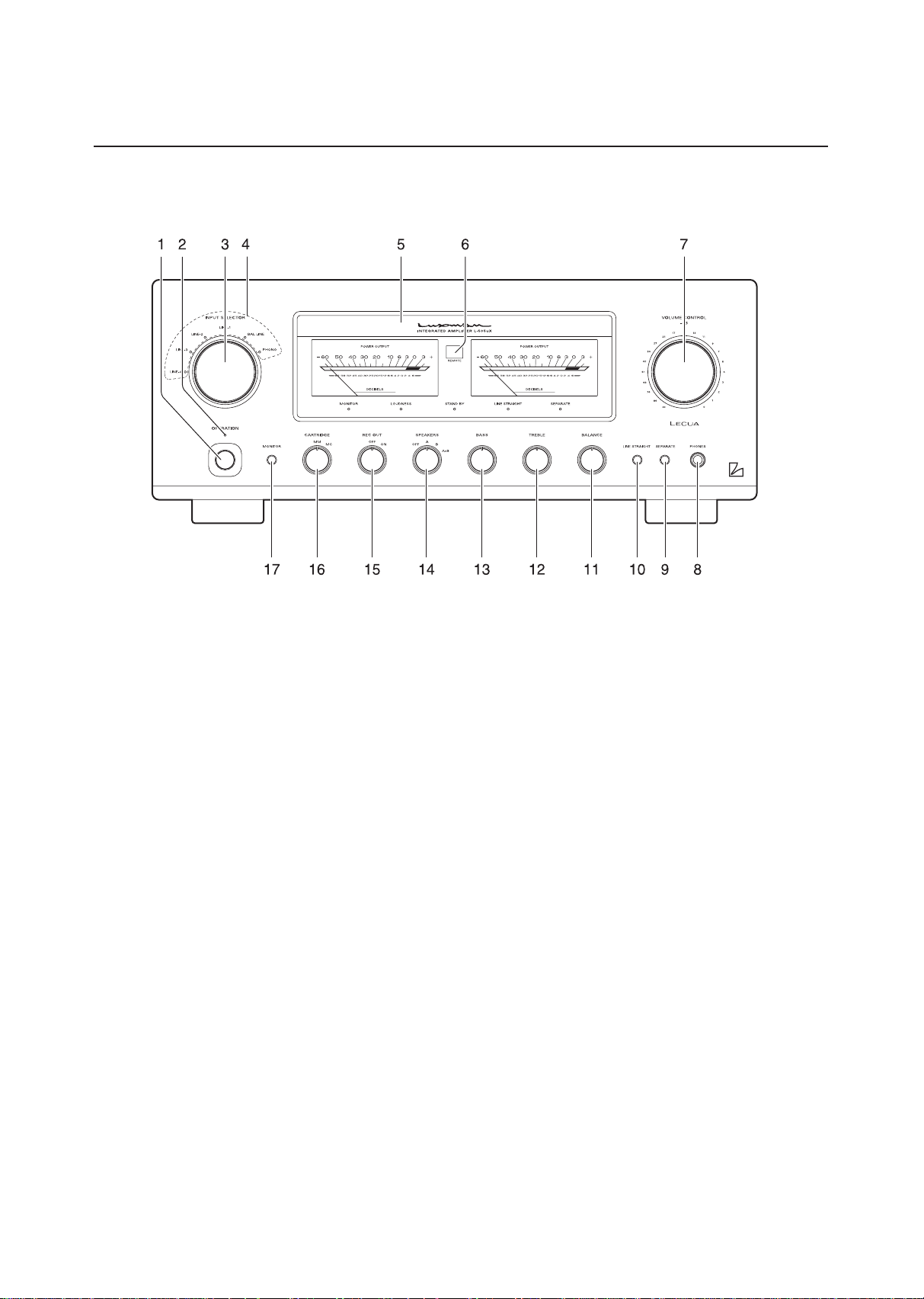
Front panel
1. Operation switch (OPERATION)
Toggles the power on and off.
When wiring or connection is performed, be sure to
turn off this switch.
2. Operation indicator (OPERATION)
Blinks in the time of muting mode when the operation
switch is turned on and lights up when the operation
state is activated afterward. This indicator blinks
when the unit is in the muting mode or when the
volume is adjusted with the remote control.
3. Input selector (INPUT SELECTOR)
Selects an input device from the devices such as a
CD player, an SACD player and a tuner connected to
each input terminal.
T
input selector has 6 positions consisting of
he
LINE-4, LINE-3, LINE-2, LINE-1, BAL LINE, and
PHONO from left to right that correspond to each
input terminal on the rear panel. The knob is rotated
to light the input indicator of the input device to be
selected.
4. Input indicator
Lights up at the input device to be selected with the
input selector or remote control.
5. Display
Displays the operation status of this unit.
This display is composed of 5 indicators and 2 power
meters.
6. Remote control infrared receiver (REMOTE)
This is a sensor to receive signals from the
accessory remote control.
7. Volume control (VOLUME CONTROL)
Adjusts the sound volume. Sound is not generated
when this control is rotated counterclockwise to the
end, and then, the sound volume gradually becomes
higher when the control is slowly rotated clockwise.
Page 7

5
NTEGRATED AMPL FIER L-505uX
8. Headphone jack (PHONES)
Insert the headphone plug into this output jack. Even
when the plug is inserted, signals to the speaker
output terminal are not interrupted. Accordingly, to
listen to sound with only use of headphones, set the
speaker selector to off.
9. Separate switch (SEPARATE)
Separates the pre-amplier and main-amplier each
other.
off:
Uses this unit as a normal pre-main
(separate
indicator off)
Feeds external signals from the MAIN
on:
(separate
indicator on)
Every pressing of this switch toggles the separate
on and off.
The separate indicator lights
switch is on.
When the separate switch is set to on, the volume control
of this unit cannot adjust the volume of the speakers
connected to this unit. Volume adjustment shall be
performed at the input device side such as the control
amplier connected to the MAIN IN terminal.
Entry of direct output into the MAIN IN terminal from a CD
player or other devices that cannot adjust sound volume
constantly provides a full power state and accordingly
results in the risk of speaker damage.
For such input devices, be sure to use a control amplier
equipped with the sound volume adjustment function as a
relay, generate sound through the speakers with volume
lowered, and adjust the volume to your favorite level.
When arranging the wiring, be sure to turn off the power
of this unit.
amplier.
IN terminal on the rear panel to the
main-amplier section.
up when the separate
10.Line straight switch (LINE STRAIGHT)
Enhances the purity of the sound quality by passing
the balance control circuit, tone control circuit, or the like.
off:
Line straight off/bypass off
(separate
indicator off)
on:
Line straight on/bypass on
(separate
indicator on)
Every pressing of this switch toggles the line
straight on and off.
The
line straight indicator lights up when the line
straight switch is on.
When the line straight switch is set to on, the balance
control, tone control and loudness cannot be adjusted
and the mode selector does not function.
11.Balance control (BALANCE)
Adjusts the balance of sound volume between right
and left channels.
Rota
This
When the line straight
ting this switch counterclockwise causes the
left sound volume to be enhanced, and rotating the
switch clockwise causes the right sound volume to be
enhanced.
switch shall be set to the center position under
normal conditions, and rotated to make adjustment if
necessary.
switch is set to on, this switch
does not function.
12.Tone control for treble (TREBLE)
Controls the frequency characteristics in the high-
frequency range.
When
When
this switch is set to the center position, flat
frequency characteristic is obtained. Rotating
the switch clockwise causes the high-frequency
range to be enhanced, and rotating the switch
counterclockwise causes the high-frequency range to
be attenuated.
the line straight
does not function.
switch is set to on, this switch
Page 8

6
Names and Functions
13.Tone control for bass (BASS)
Controls the frequency characteristics in the low-
frequency range.
When
When
this switch is set to the center position, flat
frequency characteristic is obtained. Rotating
the switch clockwise causes the low-frequency
range to be enhanced, and rotating the switch
counterclockwise causes the low-frequency range to
be attenuated.
the line straight
does not function.
switch is set to on, this switch
14.Speaker selector (SPEAKERS)
Selects either of 2 speaker systems, A or B, located
at the rear panel.
OFF:
A:
(center)
B:
A+B:
Activates only headphones. No sound is
generated from any speakers.
Selects the A system speaker terminal.
Selects the B system speaker terminal.
Simultaneously activates both A and B
system speakers. When both speaker
terminals are simultaneously used, select
speakers with impedance of 8 ohms or
more because both output terminals are
connected in parallel.
16.Cartridge selector (CARTRIDGE)
Changes the gain level of the equalizer amplifier
(amplier circuit required to play an analog record).
MC:
MM:
Selects an MC (moving coil) type cartridge
of low output voltage.
Be aware that the sound volume becomes
higher and unbalanced sound without
high frequencies is generated owing to the
impedance when “MC” is selected during
use of the MM type cartridge.
Se l e c t s an MM (m o v i n g magne t ) type
cartridge of high output voltage.
17.Monitor switch (MONITOR)
Toggles between use and nonuse of the monitor
input terminals (MONITOR) on the rear panel.
Enables to reproduce the data from the
off:
(monitor
indicator off)
Enables to reproduce the data from the
on:
(monitor
indicator on)
Every pressing of this switch toggles the monitor
on and off.
The
switch is on.
recorder.
source selected with the input selector.
monitor indicator lights up when the monitor
15.Recording switch (REC OUT)
Sends recording signals to the recorder connected to
this unit.
OFF:
ON:
Does not send recording signals to the
recorder output terminals on the rear panel.
When not using the recorder, set the
recording switch to this position.
Selects an input source to be recorded
with the input selector and sends recording
signals to the recorder connected the
recorder output terminals of this unit.
Page 9

7
NTEGRATED AMPL FIER L-505uX
Display
1. Monitor indicator (MONITOR)
Lights up when the monitor switch is on.
2. Power meters
The left meter reads the output of the L channel, and
the right meter reads the output of the R channel.
The meters read the level in decibels.
The meters light when the power is on.
3. Loudness Indicator (LOUDNESS)
Turns on when the loudness switch is on.
The loudness function can only be turned on/off with
the included remote control (RA-17).
4. Standby indicator (STAND BY)
Lights when the AC plug is plugged into a wall socket
and the operation switch is set to off. This indicator
turns off when the AC plug is disconnected from the
wall socket or the operation switch is set to on. This
indicator blinks when the protection circuit is activated.
5. Remote sensor (REMOTE)
Receive signals from the accessory remote control.
6. Line straight indicator (LINE STRAIGHT)
Lights up when the line straight switch is on.
When the line straight switch is set to on, the
loudness cannot be adjusted from the accessory
remote control.
When
Adju
one of these switches is pressed, the line
straight indicator blinks for 3 seconds to show that
this unit cannot be operated.
st the loudness after setting the line straight
switch to off.
7. Separate indicator (SEPARATE)
Lights up when the separate switch is on.
Page 10

8
Names and Functions
Rear panel
1. Signal ground (ground terminal) (SIGNAL
GROUND)
Is a ground terminal for devices to be connected
to this unit. This terminal is used to reduce noise
when other devices are connected. This terminal is
designed not for safety.
2. Phono input terminal (PHONO)
Is an input terminal to connect an analog record player.
Do not connect a CD player or other devices whose
output level is high.
Norm
al playback cannot be achieved due to sound crack.
3. LINE-1, LINE-2, LINE-3, and LINE-4 input
terminals (unbalance)
(LINE-1, LINE-2, LINE-3, LINE-4)
Are used for high-level signal inputs from a CD
player, an SACD player, a tuner, a DVD player, a TV,
and other such devices. The input sensitivity is 180
m
and the impedance is 47 kohms. These input
V,
terminals offer the same functions.
4. Recorder input/output terminals (REC)
Connect the audio input/output of a recorder. The
audio input of a recorder is connected to REC OUT,
and the audio output of a recorder is connected to
MONITOR.
Do not insert shortpin plugs into REC OUT
No sound is generated.
.
Page 11

9
NTEGRATED AMPL FIER L-505uX
5. Pre-out terminal (PRE OUT)
This terminal is used to obtain the output of the
preamplier.
A bi
Do not insert shortpin plugs into PRE OUT.
No sound is generated.
-amp connection can be performed with a
combination of an external power amplier because
this terminal always provides output regardless of the
separate switch setting.
6. Main in terminal (MAIN IN)
Provides input to the main-amplier section when the
pre-amplifier and main-amplifier are separated by
setting the separate switch to on.
7. Balance input terminals (BAL LINE)
Are the balance type input terminals of the LINE level
for the XLR connector (cannon connector).
8. Phase inverters (PHASE)
9. AC inlet (AC IN)
Connects the accessory power cable. The power
shall be supplied from a household wall socket.
10.Speaker terminals (SPEAKERS)
Connects a speaker system.
The right speaker terminal shall be connected to
the R side, and the left speaker terminal shall be
connected to the L side in consideration of the
polarity.
General type terminal
Change the phase when the balance input terminal is
used. The phase shall be corresponding to the phase
of the input device.
Normal position
Invert position
1
GROUND
2
COLD
3
HOT
1
GROUND
2
HOT
3
COLD
* It is possible
as from above.
to insert cables from below as well
Page 12

10
Connections
Page 13

11
NTEGRATED AMPL FIER L-505uX
Before connecting
Before connecting to other devices, please connect
the supplied power cable jack to the AC inlet of
this device. When connection is performed, turn off
the operation switches of these units and all other
connected devices to prevent an accident caused by
unexpected noise.
How to connect power supply
Use the accessory power cable and insert the AC
plug in an outlet on the wall in the room where the
unit will be installed.
How to connect CD player, SACD player,
tuner, or other devices
Connect between the output terminals of a CD player,
an SACD player, a tuner, or other such input devices
and
the LINE-1 input terminals of this unit with 2 (R
and L) pin-plug cables or balanced cables.
For
LINE-2, LINE-3, and LINE-4 input terminals,
connection in the same fashion as the LINE-1
terminals provides the reproduction likewise.
How to connect speakers
Connect the left-channel speaker to the LEFT
SPEAKER terminal of this unit and the right-
channel speaker to the RIGHT SPEAKER terminal.
S
If the
rely connect the
ecu
system to the speaker terminal
and the
speaker terminal
to either of the right and left speaker systems, the
acoustic phases of the sound reproduced from the
right and left speaker systems are also reversed. In
such a case, be aware that the sound level in the
low range will be reduced and the acoustic stability
will worsen, thus failing in normal stereo playback.
-
terminal of the speaker system to the
+
and - terminals are reversely connected
+
terminal of the speaker
-
(black) of this unit.
+
(red) of this unit,
Page 14

12
Connections
Page 15

13
NTEGRATED AMPL FIER L-505uX
How to connect record player
Connect between the output terminal of an analog
record player and the PHONO terminal of this unit
with 2 (R and L) pin-plug cables.
For
The phono equalizer of
If a
The
some types of
phono motor or the tone arm should be connected to
the ground terminal of this unit.
cartridge.
n MC cartridge with low output voltage is used,
set the cartridge selector on the front panel to the MC
position.
output from a record player equipped with a
phono equalizer or from an independent phono
equalizer shall be connected to the line input
terminals of this unit.
players, the ground wire from the
this unit uses the MM or MC
How to connect recorder
1. Connection to monitor terminal (playing)
Connect between the line output terminals (LINE
OUT) of a recorder and the monitor terminals of this
unit with pin-plug cables in consideration of R and L.
Now, setting the monitor switch on the front panel or
the remote control to on provides playback.
When
Do not insert shortpin
When a CD recorder
you need not toggle an input source to be
recorded (especially when a recorder connected to
the recorder output terminals is recording), do not
operate this switch.
plugs into REC OUT. No sound
is generated.
, tape recorder, or other devices
are connected, be aware that the playback sound
volume becomes low or no sound is generated if the
device extremely decreases the impedance of the
line input terminals of the recorder or causes shortcircuit on the line input terminals or if the recording
switch is set to on.
How to connect PRE OUT/MAIN IN terminal
Either the pre-amplifier or main-amplifier can be
separately used.
When
When
the pre-amplier or main-amplier is separately
used, set the separate switch on the front panel to on.
only the pre-amplifier is used, connect the
PRE OUT terminal of this unit to the input terminal
of another power-amplier, and when only the main-
amplifier is used, connect the MAIN IN terminal of
this unit to the output terminal of another power-
amplier.
2. Connection to REC OUT terminal (recording)
When the sound source from the various input
devices is reproduced, which are connected to the
PHONO or LINE terminals of this unit, setting the
recording switch to on allows users to provide the
REC OUT terminal with the signal.
C
onn
ection between the REC OUT terminal of this
unit and the line input terminals (LINE IN) of the
recorder with pin-plug cables is required for recording
on the recorder. After the connection, you can enjoy
listening to the sound from the speaker system and
record the sound at the same time.
T
e output signals for recording are not affected by
hes
the control functions such as the volume control and
tone control functions.
W
Do
this amplifier is used without separating
hen
between pre-amplifier and main-amplifier, set the
separate switch on the front panel to off, or no sound
is generated.
not insert shortpin
is generated.
plugs into PRE OUT. No sound
Page 16

14
Operations
Before operation
1. Ensure that the connections are correctly performed.
(Normal playback cannot be achieved with wrong
+
connection of R, L,
2. When the power is toggled between on and off or the
input selector is changed over, set the volume control
to the minimum position in advance.
, or
-
)
Playback procedure
1. Press the operation switch after ensuring that the
volume control is set to the minimum position.
2. S
elect a source to be reproduced with the input
selector.
3. Adjust the sound level with the volume control.
4. Operate the
tone control according to the reproduced source.
line straight switch, balance control, and
How to operate line straight switch
The line straight switch is used to play sound with the
shortest signaling route for enhancing the purity of
the source selected with the input selector. When this
switch is set to on, the balance control, tone control,
and loudness are bypassed.
How to operate the tone control
This unit has the tone control function for the low-
frequency and high-frequency ranges.
The
T
As with the low-frequency range type, the tone
F
When the line straight switch is set to on, the tone
low-frequency range type works in the 300 Hz
or lower. The tone control is set to flat frequency
characteristic at the center position. Rotating
the control clockwise causes the low-frequency
range to be enhanced, and rotating the control
counterclockwise causes the low-frequency range to
be attenuated.
he
high-frequency range type works in the 3 kHz or higher.
control is set to flat frequency characteristic at the
center position. Rotating the control clockwise
causes the high–frequency range to be enhanced,
and rotating the control counterclockwise causes the
high-frequency range to be attenuated.
or
both the low-frequency and high-frequency ranges,
the right and left channels interlockingly function.
control does not function.
How to record a source
1. Select a source to be recorded with the input selector.
How to operate balance control
The balance control allows users to adjust the
balance of sound volume between right and left
channels.
W
When the line straight
the balance adjustment is not required, the
hen
balance control is set to the center position.
switch is set to on, the balance
control does not function.
2. Set the recording switch to on.
3. Play the source to be recorded and set the recorder
to the recording state.
* Operation
not affect the recording signals.
* The recording switch works when the power is on.
of the tone control or balance control does
Page 17

15
NTEGRATED AMPL FIER L-505uX
Procedure of timer-controlled recording
1. Turn on the operation switch to activate this unit.
2. Select a source to be recorded under timer control
with the input selector.
3. Set the recording switch to on.
rform time setting for start and stop times with your
4. Pe
timer.
5. Ref
If t
When
er to the operating instructions of the timer and
other connected devices for further information.
he volume control is not set to low levels, the
source selected with the input selector may be
reproduced from the speakers. Be sure to set the
volume control to a low level.
timer-controlled recording is performed,
operations of the amplier are the same as regular use.
Procedure of timer-controlled playing
1. Turn on the operation switch to activate this unit.
2. Select a source to be reproduced under timer control
with the input selector.
Memory
This unit stores the following items when the power is
off:
Item
INPUT
METER
MONITOR
LOUDNESS
LINE STRAIGHT
SEPARATE
To be stored
Selected source
on/off
on/off
on/off
on/off
on/off
Memory reset
The following operations restore all the settings to the
factory defaults.
(1) Turn off the power of this unit.
(2)
Hold down the operation switch on the main unit for
5 seconds or more and press the line straight switch
on the main unit once, and the power state switches
from on to off.
That’
s all for memory reset.
3. Adjust the volume level with the volume control.
rform time setting for start and stop times with your
4. Pe
timer.
5. Ref
er to the operating instructions of the timer and
other connected devices for further information.
Factory default
Item
INPUT
METER
MONITOR
LOUDNESS
LINE STRAIGHT
SEPARA
TE
Default
LINE-1
on
off
off
off
off
Page 18

16
How to Use Remote Control
Remote control (RA-17)
1
2
3
4
5
1. Operation switch (OPERATION)
6
7
8
9
10
11
4. Separate switch (SEPARATE)
Toggles the power on and off.
When wiring or connection is performed, be sure to
turn off this switch.
2. Input selector
(LINE-1, LINE-2, LINE-3, LINE-4, BAL-1,
BAL-2, PHONO, MONITOR)
Selects an input terminal from among the unbalanced
input terminals on the rear panel consisting of
LINE
-1, LINE-2, LINE-3, LINE-4, PHONO, and
MONITOR or the balanced input terminal consisting
of BAL LINE.
* The
balanced input ter minal (BAL LINE) can be
selected by pressing either of BAL-1 or BAL-2.
3. Monaural switch (MONO)
This switch is not operated in L-505uX.
Separates the pre-amplier and main-amplier each other.
off:
(separate
indicator off)
on:
(separate
indicator on)
•
The
ding down this switch for 1 second toggles the
Hol
separate switch on and off.
separate indicator lights up when the separate
switch is on.
Uses this unit as a normal pre-main
amplier.
Feeds external signals from the MAIN
IN terminal on the rear panel to the
main-amplier section.
5. Mute switch (MUTE)
Activates the mute function and blinks the power-on
indicator resulting in no sound generated.
Pressing this button again
off allows sound to be generated.
to set the mute function to
6. Meter switch (METER)
Turns off the meter lights.
Pressing this switch again turns on the meter lights again.
Page 19

17
NTEGRATED AMPL FIER L-505uX
30°30°
7. Subsonic switch (SUBSONIC)
This switch is not operated in L-505uX.
8. Loudness switch (LOUDNESS)
Psychoacoustically compensates the frequency
characteristics when the volume control is set to the
center position or lower.
T
• Every pressing of this
The l
* When
compensation allows listeners to complement
his
human listening characteristics when the sound
volume is in the low level.
switch toggles the loudness on
and off.
oudness indicator lights up when the loudness
switch is on.
the line straight switch is set to on, this switch
does not function.
9. Line straight switch (LINE STRAIGHT)
Enhances the purity of the sound quality by
bypassing the balance control circuit, tone control
circuit, or the like.
Line straight off/bypass off
off:
(line straight
indicator off)
Line straight on/bypass on
on:
(line straight
indicator on)
• Every pressing of this switch toggles the line straight
on and off.
11.Volume (VOLUME, , )
This button is used to adjust the sound volume. The
sound volume is lowered with
and raised with .
Remote control
The remote control shall be aimed at the remote
sensor of this unit within the specified angle range
shown in the illustration when used.
Effective distance: approx. 5 m
Dry cell [How to load batteries]
1. Put your nger on the battery cover claw on the rear
of the remote control, and slide the cover downward
to open it.
t 2 AAA batteries in the battery case as shown in
2. Pu
the illustration.
3. Close the battery cover.
ine straight indicator lights up when the line
e l
Th
straight switch is on.
10.CD/SACD player operation switch
(CD/SACD PLAYER)
This switch is used to control the corresponding CD/
SACD players.
As of October 2010,
are D-08, D-06, D-05, D-10, D-7, D-600, and D-700S.
the corresponding CD/SACD players
en
* Wh
*
the batteries start to lose power, the effective
distance becomes shorter or the unit does not
function even though the switch is pressed. In such a
case, both of the batteries shall be replaced with new
ones at the same time.
he remote control is not used for a long time, the
If t
batteries shall be removed from the case.
Page 20

18
Block Diagram
Page 21

19
NTEGRATED AMPL FIER L-505uX
Specications
Continuous power output 100W + 100W (8Ω)
150W + 150W (4Ω)
Total harmonic distortion 0.005% (8Ω, 1 kHz both channels simultaneous drive, line straight on)
0.04% (8Ω, 20 Hz to 20 kHz both channels simultaneous drive, line straight on)
Pre-ampli
Input sensitivity/input impedance
Main-ampli
Input sensitivity/input impedance
Output voltage REC OUT : 180mV
S/N ratio
Frequency response PHONO(MM) : 20Hz to 20,000Hz (within -3dB, line straight on)
er
e
PHONO(MM)
PHONO(MC) : 0.3mV / 100kΩ
LINE : 180mV / 47kΩ
MONITOR : 180mV / 47kΩ
BAL LINE : 180mV / 79kΩ
MAIN IN
PRE OUT : 1V
PHONO(MM) : 91dB or more
(IHF-A weighted, 5mV input)
PHONO(MC) : 75dB or more
(IHF-A weighted, 0.5mV input)
LINE : 105dB or more
(IHF-A weighted, input shorted, line straight on)
PHONO(MC) : 20Hz to 20,000Hz (within -3dB, line straight on)
: 2.5mV / 47kΩ
: 1 V / 47kΩ
LINE : 20Hz to 100,000Hz (within -3dB, line straight on)
Tone control Max. amount of change BASS: ±8dB at 100Hz
TREBLE: ±8dB at 10kHz
Loudness control 100Hz
10kHz : +5dB
Damping factor : 180
Accessories · Remote control RA-1
· Owner’
· Safety cautions
Power supply voltage 2
Power consumption 300W
Max. external dimensions 440(W) x 178(H) x 454(D)mm
Weight 22.0kg (main unit only)
30V ~ 50Hz
0.4W (at standby), 85W (at no input)
: +7dB
7 · Power cable
s Manual · size “AAA” batteries (2 pieces)
* Specications and appearance are subject to change without notice.
Page 22

20
Before Asking for Repair Services
While the unit is used, an unusual phenomenon may be confused as a malfunction for a certain reason. Prior to asking
us for repair services, please check the table below and read the instruction manual for the subsidiary devices. If the
cause of the malfunction cannot be identied, please contact your dealer.
Problem Cause Solution
No power is supplied even
though the operation switch
is pressed.
The power plug is disconnected from the
・
wall outlet, or it is not completely inserted.
The power plug is disconnected from the
・
AC inlet, or it is not completely inserted.
Insert the power plug in the wall outlet
・
securely.
Insert the power plug in the AC inlet
・
securely.
No sound is generated.
No sound is generated out on
one side.
Humming sound (boon or zzz
noise) is generated.
The volume control is set to the
・
minimum level.
The input selector is not set to the
・
source to be reproduced.
Cable connections are incomplete.
・
The output level of the input device is
・
set to the minimum position.
The separate switch is set to on.
・
The mute switch of the remote control is
・
set to on.
The balance control is fully rotated.
・
The connecting cable is not connected
・
on one side only.
The ground side of the pin-plug cable
・
has no contact with the terminal.
The ground wire of the record player
・
is not connected.
Rotate the volume control clockwise to
・
adjust the sound volume.
Set the input selector to the source to
・
be reproduced.
Make cable connections securely.
・
Adjust the output level.
・
Set the separate switch to off.
・
Set the mute switch to off.
・
The balance control shall be set to the
・
center position under normal conditions.
Make cable connections securely.
・
Make connections securely so that the
・
ground side of the pin-plug cable can
be connected.
Connect the ground wire of the record
・
player to the GND terminal.
No effect of tone control or
balance control is observed.
The loudness is not activated.
The lights of the powzer
meters are not turned on.
The separate switch of
the remote control is not
activated.
Connections or mounting conditions are
・
incomplete between the cartridge and
shell, or between the shell and tone arm
of the record player.
The line straight switch is set to on.
・
The line straight switch is set to on.
・
The meter switch is set to off.
・
To prevent incorrect operations, this unit
・
is designed to toggle the separate on/off
by holding down the separate switch
approximately for approx. 1 second.
Connect (or mount) the cartridge,
・
shell, and tone arm securely.
When tone control or balance control
・
is used, the line straight switch shall
be set to off.
When the loudness is used, the line
・
straight switch shall be set to off.
Set the meter switch of the remote
・
control to on.
Hold down the separate switch of the
・
remote control for approx. 1 second.
Page 23

21
NTEGRATED AMPL FIER L-505uX
MEMO
Page 24

LUXMAN CORPORATION, JAPAN
AG00987E02A
Printed in China
 Loading...