

Luxman L-505-U Owners Manual

INTEGRATED AMPLIFIER
L-505u
Owner`s Manual

Contents
Precautions...................................................................................................................3
Names and Functions...................................................................................................4
Connections................................................................................................................10
Operations ..................................................................................................................12
How to use remote control..........................................................................................14
L-505u Block Diagram ................................................................................................15
Specifications..............................................................................................................16
Before asking for repair services ................................................................................17
2
Precautions
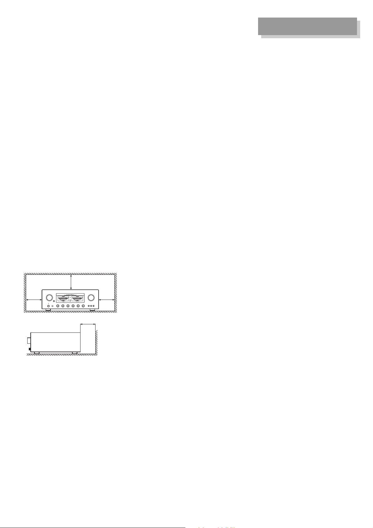
Installation place
This unit shall be installed in a well-
ventilated and effectively heat-
released place.
Especially, installation of this unit
where direct sunlight is present,
where the temperature rises exces-
sively high such as close to a heater,
or where it is humid or dusty may
cause a malfunction even if heat is
efficiently released. Therefore, do not
install this unit in such places.
Ventilation holes
If the amplifier is installed on a rack or
the like, secure ample space for cool-
ing and leave the door open. Do not
pile up other things on the amplifier
and never put articles on it. Failure to
observe this may cause a malfunction.
Note:
For heat dispersal, do not install this
equipment in a confined space such
as a book case or similar unit.
* Note
* *
*
Wall
Precautions in connecting
with other components
When connecting this unit to input
devices such as a CD/DVD player, a
tuner, and a recorder, be sure to turn
off the power of this unit and all other
connected devices. Failure to observe
this may generate a strong noise
resulting in speaker damage or cause
a malfunction.
The pin-plug to be inserted in each
input terminal of this unit shall be
pushed in firmly. If the grounding ter-
minal is inadequately connected, nois-
es including hum may be generated,
resulting in an adverse S/N ratio.
Cautions in connecting
speakers
When making speaker system con-
nections, exercise extra care not to
short-circuit between ! and @ of the
speaker terminals and speaker input
terminals of this unit. If a large signal
is applied to the amplifier with its cir-
cuit left short-circuited, a large current
may be passed through the output cir-
cuit and cause a malfunction.
The sound is not generated
shortly after the power supply
is turned on.
This amplifier is equipped with a time
muting circuit in order to separate the
output circuit. Therefore, no sound is
generated shortly after the power sup-
ply is turned on.
If the volume control is moved to a
high sound level before the time mut-
ing circuit is canceled, a large sound
is suddenly generated. Please be
advised that the volume control shall
be set to a low level at first and adjust-
ed after sound comes out of the
speakers.
Protection circuit
This product is equipped with the pro-
tection circuit that is activated upon
detection of overcurrent, abnormally
high temperature, and DC drift to pro-
tect the amplifier and speakers. When
the protection circuit is activated, the
output to the speaker terminal is shut
off and the standby indicator blinks to
show that this unit is in the muting
state. If the protection circuit is fre-
quently activated after a lapse of a
certain time and turning on the power
again, please consult your dealer.
Batteries
Caution:
Batteries used for remote controller
shall not be exposed to excessive
heat such as sunshine, fire or the like.
Repair and adjustment
When repairs or adjustments are
needed, please ask the dealer where
you bought the unit.
Cleaning
For cleaning, use a piece of soft cloth
to wipe the unit such as cleaning cloth
available on the market. If the unit has
become remarkably dirty, remove the
dirt with soft cloth absorbing a small
amount of neutral detergent, and then
wipe the unit with dry cloth. Do not
use a solvent like benzine or thinner
because such a substance can dam-
age the exterior.
3
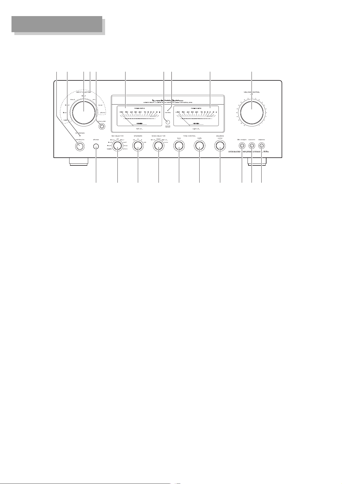
Names and Functions
Front panel
12
43
56 78
1. Power switch
(stand by/on)
Toggles the power on and off.
When wiring or connection is per-
formed, be sure to turn off this
switch.
2. Operation indicator
(OPERATION)
Blinks in the time muting mode
when the power switch is turned on
and lights up when the operation
state is activated afterward. This
indicator blinks when the unit is in
the muting mode or when the vol-
ume is adjusted with the remote
control.
96
10111213141516171819
3. Input selector
(INPUT SELECTOR)
Selects an input device from the
devices such as a CD/DVD player
and tuner connected to each input
terminal. The input selector has 8
positions consisting of bal. line, line-
4, line-3, line-2, line-1, rec-1, rec-2,
and phono that correspond to each
input terminal on the rear panel. The
knob is rotated to light the input
indicator of the input device to be
selected.
4. Input indicator
Lights up at the input device to be
selected with the input selector or
remote control.
4

Names and Functions
5. Phono MC cartridge on/off
switch (phono MC)
Changes the gain level of the
equalizer amplifier (amplifier circuit
required to play an analog record).
MC : ON is selected by pressing
this switch when MC (mov-
ing coil) type cartridge of low
output voltage is used.
Be aware that the sound vol-
ume becomes higher and
unbalanced sound without
high frequencies is generat-
ed owing to the impedance
when “MC” is selected dur-
ing use of the MM type car-
tridge.
MM : OFF is selected when MM
(moving magnet) type car-
tridge of high output voltage
is used.
6. Power meters
The left meter reads the output of
the L channel, and the right meter
reads the output of the R channel.
The meters read the level in deci-
bels.
The meters light when the power is
on.
7. Remote sensor
(remote sensor)
Receives signals from the accesso-
ry remote control.
8. Standby indicator
(stand by)
Lights when the AC plug is plugged
into a wall socket and the power
switch is set to off.
This indicator turns off when the AC
plug is disconnected from the wall
socket or the power switch is set to
on. This indicator blinks when the
protection circuit is activated.
9. Volume control
(VOLUME CONTROL)
Adjusts the sound volume. Sound
is not generated when this control
is rotated counterclockwise to the
end, and then, the sound volume
gradually becomes higher when the
control is slowly rotated clockwise.
10. Separate switch (separate)
Separates the pre-amplifier and
main-amplifier each other.
: Uses this unit as a normal
pre-main amplifier.
: Feeds external signals from
the MAIN IN terminal on the
rear panel to the main-ampli-
fier section.
When the separate switch is set to
on, the volume control of this unit
cannot adjust the volume of the
speakers connected to this unit.
Volume adjustment shall be per-
formed at the input device side such
as the control amplifier connected to
the MAIN IN terminal.
Entry of direct output into the MAIN
IN terminal from a CD/DVD player
or other devices that cannot adjust
sound volume constantly provides
a full power state and accordingly
results in the risk of speaker dam-
age.
For such input devices, be sure to
use a control amplifier equipped
with sound volume adjustment
function as a relay, generate sound
through the speakers with volume
lowered, and adjust the volume to
your favorite level.
5
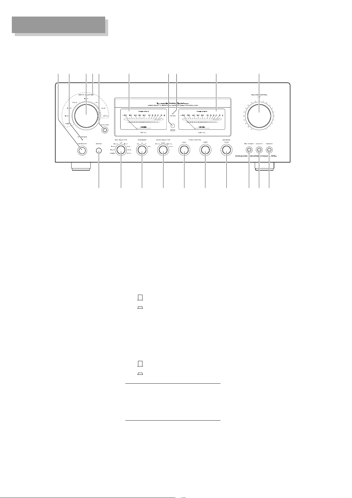
Names and Functions
Front panel
12
43
56 78
11. Subsonic (subsonic)
Cuts ultra-low frequencies out of
audible range to prevent ultra-low
range noise from adversely affecting
audible range. This function is signif-
icantly effective especially when a
record is warped or a woofer is
shaking owing to ultra-low range
vibration.
: Subsonic off
: Subsonic on
12. Line straight (line straight)
Enhances the purity of the sound
quality by bypassing the balance
control circuit, tone control circuit, or
the like.
: Line straight off/bypass off
: Line straight on/bypass on
96
10111213141516171819
13. Balance (BALANCE)
Adjusts the balance of sound vol-
ume between right and left chan-
nels.
Rotating this switch counterclock-
wise causes the left sound volume
to be enhanced, and rotating the
switch clockwise causes the right
sound volume to be enhanced.
This switch shall be set to the cen-
ter position under normal condi-
tions, and rotated to make adjust-
ment if necessary.
When the line straight switch is set
to on, this switch does not function.
When the line straight switch is set
to on, the balance control and tone
control cannot be adjusted and the
mode selector does not function.
6
 Loading...