

Lucent Technologies OneVision DEFINITY G3 Fault Management Installation And Integration Manual
Page 1

OneVision Definity G3
Fault Management Installation and Integration for IBM NetView on AIX
585-229-114
Comcode
107705659
Issue 1
Page 2

Copyright 1996, Lucent Tec hnologies
All Rights Reserved
Printed in U.S. A.
Notice
Every effort was made to ensure that the information in
this boo k w as complete and accurate at the time of printing. However, information is subject to change.
Your Responsibility for Your System’s Security
Toll fraud is the unauthorized use of your telecommunications sys tem by an unauthor ized party, for example,
persons other than your company’s employees, agents,
subcont r actors, or pers ons w orking on your company’s
behalf. Note that there may be a risk of toll fraud associated with your tel ecommunicatio ns s ystem and, if toll
fraud occurs, it can result in substantial additional
charges for your telecommu nications servi ces.
Order: Document No. 585-229-114
Comcode 107705659
Issue 1, August 1996
For additional documents, refer to the section entitled,
“Related Documents” in “About This Book.”
You can be placed on a Standing Order list for this and
other documen ts yo u may need . St and in g Order w ill
enable you to automatically receive updated versions of
individual documents or do cument sets, bill ed to
account information that you provide. For mor e information on St anding Orders, or to be put on a list to
receive future issues of this document, please contact
the Lucent Techn o logie s Pu bl icat io ns Cente r.
Comments
To comment on this document, return the comment card
at the front of the document.
You and your s ystem manager are res ponsible for the
security of your system, such as programming and configuring your equipment to prevent unauthorized use.
The system manager is also responsible for reading all
installation, instruction, and system administration documents provided with this product in order to fully
understand the features t hat can introduce r isk of toll
fraud and the steps that can be taken to r educe that risk.
Lucent Technologies does not warrant that this product
is immune from or w ill prevent unauthorized use of
common-carrier telecommunication services or facilities
accessed through or connected to it. Lucent Technologies w il l no t be r es p onsibl e f or any cha r ge s t ha t r e s ul t
from such unauthorized use.
Lucent Technol ogies Fraud Inte rvention
If you susp ect th at you are be in g victimi zed by tol l fraud
and you need technical support or assistance, call Technical Service Center Toll Fraud Intervention Hotline at
1 800 643-2353.
Trademarks
xxx is a trademark of xxx corp.
Ordering Information
Call: Lucent Technologies Publications Center
Voice 1 800 457-1235
International Voice 317 361-5353
Fax 1 800 457 -1764
International Fax 317 361-5355
Write: Lucent Technologies Publications Center
P.O. Box 4100
Crawfordsville, IN 47933
Acknowledgment
This document was prepared by the Product Documentation Development group, Lucent Technologies, Denver, CO.
Page 3

Contents
About This Bo ok vii
■ Audience vii
■ Pr er equisites vii
■ Convent ions ix
■ Trademarks x
■ Credentials x
■ Your Fault Management Documentation Package xi
Online Documentation xi
■ Reader Comments xii
1 Before You Begin 1
■ Over v iew 1
Fault Management 2
Standard Network Management Components 2
Network Connectivity 4
■ Installation and Setup Task List 5
■ Requirements for Fault Management Installation 8
Certification 8
2 Installation 9
■ Installation Prereq uisit es 9
■ Installation Procedures 10
Issue 1 August 1996 iii
Page 4

Contents
■ Changing the E nvironment 11
3 Integra t ion 13
■ Adding DEFINITY G3 PBX Nodes 14
Node Limitat ions 14
Adding a PBX as a Managed Node 14
Adding a PBX Icon 14
Configu ring a PBX Object 16
■ Adding DEFINITY G3 Proxy Agent Nodes 19
Node Limitat ions 19
Adding a Proxy Agen t as a Managed Node 19
Adding a Proxy Ag ent Icon 19
Configuring a Proxy Agent Icon 21
4 Starting the Applications 25
■ Starting Fault Management 25
Starting from the Network Map 25
Starting with the Mouse 26
■ Opening the Online User Guide 27
Opening from the Network Map 27
Open ing from a Shell Prompt 28
■
Dyna
Text Documentation 28
iv Issue 1 August 1996
Page 5

Contents
5 Alarm States 29
■ States of the DEFINIT Y G3 Icons 30
Icon States 30
Conditions Causi ng Change of State 31
■ States of the Proxy Agent Icons 32
Icon States 32
Conditions Causi ng Change of State 33
■ Verifying Connectivity 34
Icon State 34
Startup Messages 34
Startup Screen 35
Switch View 36
Warning Messages 36
Data Refr eshes 37
Refreshing Data Manually 37
The MIB 37
Trouble sh ooting Disconnects 38
A Advanced Customization 41
■ Changing the Polling Int e r v al 42
■ Changing Defaul t Valu es 42
The Setup Screen 43
The Ap plication Resource File 43
Accessing the Resource File 43
Default Values 44
Editing the File 44
Issue 1 August 1996 v
Page 6

Contents
■ Other Options 45
Changing Script Files 45
Changing the Application Directory 45
Changing the MIB 46
B Telnettin g to the Proxy Agent 47
■ Overview of the Proxy Agent 47
■ Why S hould You Access the Proxy Agent? 48
■ Telnetting to the Proxy Agent 49
IN Index 51
vi Issue 1 August 1996
Page 7

About This Book
This book provides information about DEFINITY G3 Fault Management and
Proxy Agent connectivity and tells you how to install and initially set up y our
DEFINITY G3 ap plication.
Audience
This book is intended for DEFINITY Generic 3 cus tom ers who use DEFINITY
G3 Fault Management (referred to hereafter as Fault Management) to manag e
their PBXs on the IBM
NetV iew 4.1.
Prerequisites
The level of information p rovided in this book is based on the assumption that
users have f u lf illed the following pr er equis it e s :
■ Customers must understand the network management system (NMS ) on
which Fault Manageme nt resides. It is not within the scope of this or
other Fault Management documentation to describe how to use the
NMS beyond what the Fault Managem ent software requires.
■ Customers must understand their DEFINITY G3 PBX configuration and
must be familiar with basic PBX alarm and error functionality.
Issue 1 August 1996 vii
Page 8

Prerequisites
How This B ook Is Organized
This book is organi zed as follows:
Chapter 1 Lists the hardware and software that is certified to run Fault
Management and provides preparatory steps.
Chap ter 2 Gives you the p roced ures fo r installing the software.
Chap ter 3 Provid es information for integrating Fault Manag em ent and
Proxy Agent into the NMS.
Chapter 4 Explains how to start Fault Management and the online user
guide.
Chapter 5 Describ es the states, alarms, po lls, and masks, for
DEFINITY G3 PBXs and for DEFINITY Proxy Agents.
Appendix A Describes how to change polling intervals and default
colors.
Appendix B Explains how to telnet to the Proxy Agent.
This book also contains an index.
viii Issue 1 Aug us t 1996
Page 9

Conventions
Conv entions
This book contains th e following typ ographic conventions:
■ Information that is displayed on your screen is shown in typew riter-style
constant-width type.
Example: Installation complete.
■ Information that you enter from your keyboard or select from a menu is
shown in bold type .
Example: Enter attov_doc.
Click OK.
■ Keys that you press are indicated by small type.
Example: Press
■ The word "Enter" means to type the word shown in bold text, then press
Enter key.
the
Enter.
Example: Enter the command tar.
Means type tar and then p res s
■ Brackets indicate values that you supply.
Enter.
Example: public!g3mgt!<client string> means that
you determine the value of the client string.
Issue 1 August 1996
ix
Page 10

Trademarks
Trademarks
The following trademarked products are mentioned in this document:
■ DE FINITY is a registered trademark of AT&T
■ OneVision is a trademark of AT&T
■
Dyna
Text is a trad ema rk of Electronic Book Technologies, Inc.
■ IBM, NetView, and AIX are trademarks or reg i s tered trade marks of IBM.
Credentials
The developm ent proces s for DEFINITY G3 Fault Managem ent is ISO 9001
certified.
x Is sue 1 Aug u st 1996
Page 11

Your F ault Management Documentation Package
Your Fault Management
Documentation Package
Your Fault Management documentation pa ckag e includes two parts:
■ The installation guide (this book)
■ Online documentation
Online Documentation
Two types of online documentation are available with Fault Management:
■ Online help provides informa tion about the Fault Management screen
that is currently ac t ive when you request help .
■ The
Network Management Solutions DEFINITY G3 Fault Management
user guide p rov ides an overview of Fault Management features, tells
you about menus and window elements, and provides detailed
information on how to use the software. You can move easily around the
guide, and can d isplay it on your monitor while Fault Management is
running.
This user g uide, which is external to the Fault Management software, is
delivered online by
Text software.
Dyna
Text is a text browser that
Dyna
allows you to move easily through a docum ent. The document appears
online in book format.
Issue 1 August 1996
xi
Page 12

Reader Comments
Reader Comments
Pl ease fill out the reader comment card. If the comment card has been
removed from this book, please send your comments to the following address:
Lucen t Techno logies
Product Documentation Development
Room 22-2C11
11900 North Pecos S treet
Denver, Colorado 80234
Fax: (303) 538-1741
Please inc lude the following informa tion:
■ The name of this document:
DEF INIT Y G3 Fault Management Installation
and Inte gration for OneVision
■ Your platform: AIX
■ Your network manag em ent system (NMS): IBM NetView
xii Issue 1 Aug us t 1996
Page 13

Before You Begin
This chapt er covers information you need to know before you begin
installing and setting up Fault Management, including:
■ Overview of Fault Management
■ Requirements for Fault Management Installation
■ Sup ported Systems
■ Hardware and Software Requirements for Fault Managemen t
■ Installation and Setup Task List
Overview
1
This section is a high-level overview of Fault Management. It also gives
users who are new to network manag eme nt systems a brief descrip tion of
the com ponents of Fault Manageme nt’s functionality, including how it fits
into the network management picture.
Issue 1 August 1996 1
Page 14

Before You Begin
Fault Management
Fault Management allows you to manage a DEFINIT Y G3 PBX as a node on
your network similar to other devices on your network. Fault Management
receives PBX data via your network management system (NMS) .
The NMS receives the PBX data from the G3 Proxy Ag ent. The purpose of
the Proxy Agent is to receive PBX data and to translate that data, which is in
DEFINITY’s OSSI (Operating Support System Interface) format, to the
SNMP (S imple Network Management Protocol) format required by the NMS.
In addition, the Proxy Agent receives alarms dat a from the PBX and
translates that data into SNMP. It also provides administrative access to
t he PB X.
With the PBX data available to the NMS, you can see alarm c onditions on
any PBX that is a node on your NMS exactly as with other devices. From the
nod e ma p you ca n execute Fault Manageme nt to get data on the PBX.
Fault Management provides a graphical interface to that information, so that
you can quickly see where on a PBX fault cond ition s exist and d isplay
reports about those fault conditions.
Standard Network Management Components
The stan dard SNMP-based management system consists of the following:
■ An object or objects to be managed, in this case one or more DEFINITY
G3 PBXs
■ An agent for managing the object(s)
It is the agent that communicates all management command responses
and information between the managed object and the NMS. The agent
can be impl eme nted as pa rt of the managed objec t, in which case it is
known as a native agent, or it can be implemented on a separate
computer, in which case it is known as a proxy agent. For DEFI NITY G3
objects, the agent is a proxy agent because it is not built into the
DEFINITY G3 PBXs. Typically, there is one agent for eac h managed
object. However, the DEFINITY G3 Proxy Agent can support up to a
2 Issue 1 Aug ust 1996
Page 15

Overview
■ A Management Information Base (MIB) resident on the agent and on the
■ One (or more) network management stations, where the management
Fault Management resides on the NMS and provides functionality beyond
the standard set of components: the ability to manage a PBX as a node on
the network.
maximum of fifteen DEFINITY G3 P BXs. The exact number of PBXs the
DEFINITY G3 Proxy Agent ca n supp ort dep e nds on the cus tom er’s
system configuration and networking capability.
NMS
The MIB is a virtual data store used to transfer all information and
com ma nds b etw een the NMS and the agent via the SNMP. MIB-II is a
standard ind us try-wide MIB. The ap plic at ions use two groups from
MIB-II and a specialized MIB called G3-MIB. Within the DEFINITY G3
environment,
refers to the
system
and
snmp
group s from MIB-II
MIB
plus the entire G3-MIB.
functions are performed using network management system (NMS)
software
In this case, the NMS is IBM NetView.
SEE ALSO:
For in depth information about Fault Management, refer to the online
Network Management Solutions DEF INITY G3 Fault Management
guide.
Issue 1 August 1996
user
3
Page 16
Before You Begin
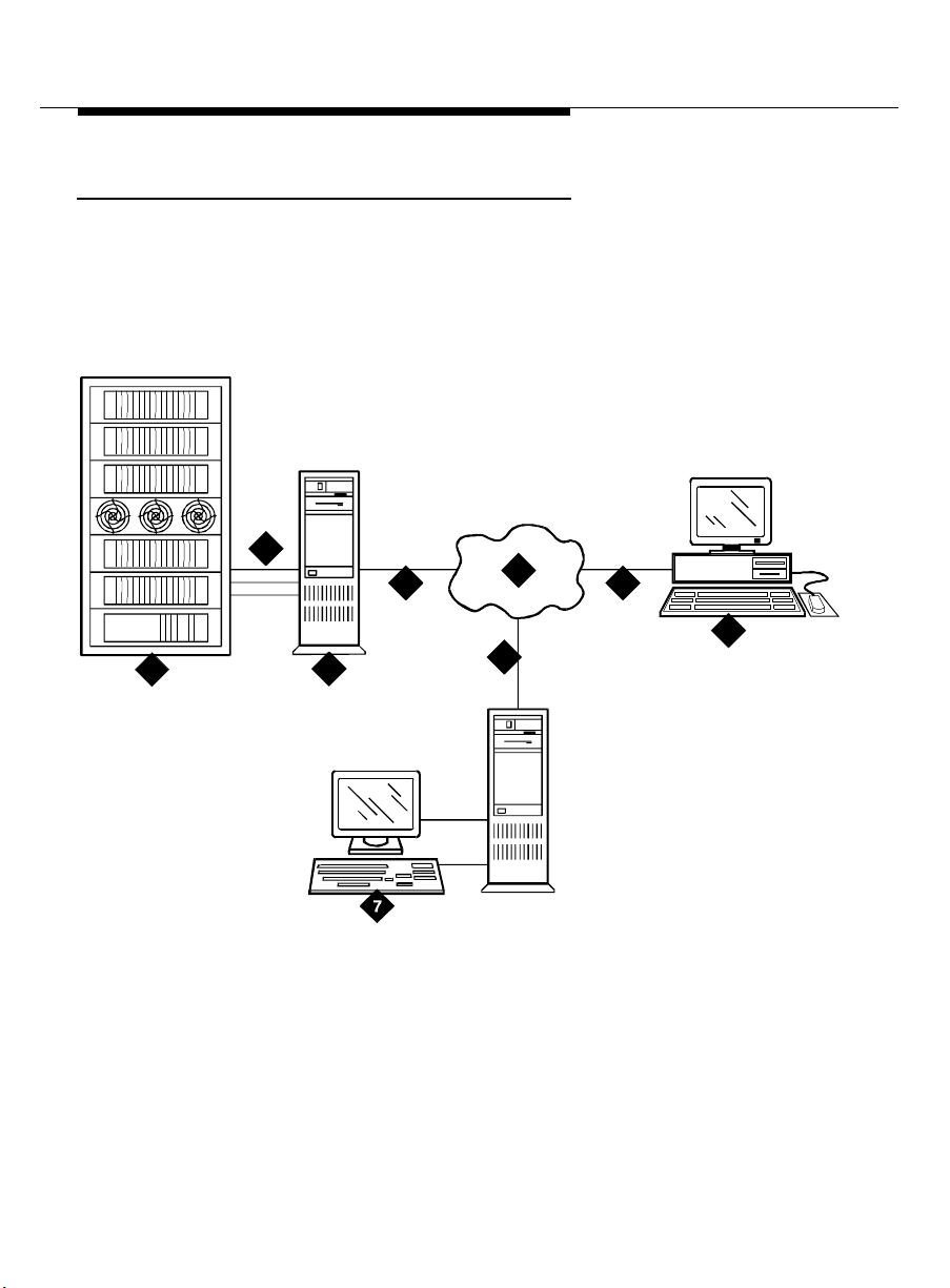
Network Connectivity
The SNMP runs on a TCP/IP link. Therefore, the connection between the
NMS and the P roxy Agent is a TCP/IP network. The following figure
illustrates the SNMP connections b et ween the NMS, Fault Manag ement,
and the Proxy Agent .
2
4 4
1
3
5
4
6
4 Issue 1 Aug ust 1996
Page 17

Installation and Setup Task List
Leg end:
1. DEFINITY G3
2. System acc ess ports
3. DEFINITY G3 Proxy Agent
4. TCP/IP
5. Internet/LAN/WAN
6. X-terminal
7. NMS
■ Operating system = AIX
■ NMS platform
■ DEFINITY G3 Fault Manag ement
Installa tion and Setup Task List
This section provi des a list of tasks, in the recommended order, to perform
while ins ta lling an d setting up Fault Management . Use this lis t t o check off
your installation act ivities as you comp l ete them. You may want to make
your own task list based on this one, and include persons or org an izations
responsible and dates to be completed.
NOTE:
These procedures assume that installation of Management
Solutions DEFINITY G3 Proxy Agent has occurred or will occur
shortly. You can install Fault Management without the Proxy Agent
being installed , but without the Proxy Ag ent up and running
properly and until the full connectivity is established, the NMS will
not receive any PBX data. Furthermore, communication between
the Proxy Agent and Fault Management requi res correlation
between values in specific fields on the Proxy Agent and NMS
admin istration. Therefore, you should plan some coord ina tion for
installing th ese two applications.
Issue 1 August 1996
5
Page 18

Before You Begin
❏ Verify the environment is correct (Chapter 1)
Make sure you have the required operating system and network
conne ctivity already set up.
❏ Verify hardware (Chapter 1)
Make sure you have all the required hardware and that the hardware
meets the certification req u irem ents. Also make sure you have enough
space on the hard drive.
❏ Verify existing software (Chapter 1)
Make sure the versions of your operating system and the NMS are
correct
❏ Prepare for software installation
■ Do you have the DEFINITY G3 Fault Manag em ent Release 1.2
tape?
■ Plan for the time needed to install the software (about ½ hour)
❏ Install the software (Chapter 2)
❏ Make changes to the environment, suc h as upd at ing the PATH variable
(Chapter 2)
❏ Restart your NMS
❏ Add t he DEFINITY PBXs as nodes on the NMS
(Chapter 3)
❏ Add t he Proxy Agent(s) as a nod e(s) on the NMS
(Chapter 3)
❏ R un Fault Management from the appropriate menu on your NMS
(Chapter 4). Verify that Fault Managem ent
■ Executes properly
■ Is receiving dat a from the Proxy Agent
❏ R un the Test INADS command on the PBX to test alarm rec eption (if
applicable)
❏ Customize Fault Manag ement
6 Issue 1 Aug ust 1996
Page 19

Installation and Setup Task List
■ Change polling intervals
■ Change user-interface characteristics
SEE ALSO:
For instructions on cus tomizing Fault Management, refer to the
Network Management Solutions DEF INITY G3 Fault Management
guide.
❏ Run the online guid e to verify it is installed and executes c orrectly
(Chapter 4)
user
Issue 1 August 1996
7
Page 20

Before You Begin
Requireme nts for Faul t Management Installation
For Fault Management to be installed and to run properly, your NMS must
be set up with the following:
■ IBM NetView 4.1
■ An IBM AIX workstation whic h meets all hardware req uirement s
■ The AIX 4.1 operating system
■ A 1/4-inch tape drive
■ 20 Mbytes of random ac cess memory
■ At least 30 Mbytes of free space on the hard drive
Certifi ca tion
Fault Management is desig ned to run on the AIX operating syst em . Lucent
Technologies does not explici tly certify any hardware , but does support
Fault Management on any hardware that is certified b y IBM .
8 Issue 1 Aug ust 1996
Page 21

Installation
This chapter provides the procedures to install your Fault Management
software. The instructions in this chapter are designed for the system
administrator. Procedures for setting up Fault Management within your
NMS are in subseq uent chapt ers.
This chapte r co vers:
■ Installation Prerequisites
■ The steps to install Fault Manag em ent
■ Chang ing your Operating Environment
2
Installation Prerequisites
Before you install Fault Management, be sure you have read Chapter 1, and
be sure that your computer environment meets all the stated hardware and
software requirements.
Issue 1 August 1996 9
Page 22

Installation
Installation Procedures
The Fault Managem ent installation is fully automated (however, after the
installation is complete, you will need to make some b a sic c hanges to your
operating environment). Once you execute the command to install the Fault
Management applic a tio n and all related software, the system completes
the installation without any need for intervention on your part.
Use the following steps to install Fault Management:
1. Insert the tape into the tape drive.
2. Log into th e operating sy stem as root.
3. Change directory to the root directory “/”.
4. Enter the following command:
tar xvf <tape device name>
5. Change to the following directory:
/usr/OV/OneVison/bin
6. Enter the following command:
./dg3fm_configure
The installation proc edure c om pletes the following:
■ Registers the applicat ion name with the NMS
■ Creates the necessary directory structure and copies all the
necessary files, include the bitmap, MIB, default database,
script, and application files
■ Installs the Fault Management application
■ Incorporates the new fields
■ Compiles the new bitmaps
■ Incorporates the DEFINITY G3 MIB into the existing M IB
■ Insta lls the
10 Iss ue 1 August 1996
Dyna
Text online d ocumentation
Page 23

Changi ng th e En vironment
7. Restart your NMS before accessing the OneVision application.
Changing the Environment
After the installation is complete, you need to change your operating
environment so you can run the online documentation from a shell prompt:
Add /usr/OV/OneVision/bin to your PATH variable.
Issue 1 August 1996
11
Page 24

Installation
12 Iss ue 1 August 1996
Page 25

Integration
This chapter provides information about integrating Fault Management with
your NMS.
This chapte r co vers:
■ A dding DEFINITY G3 PBX Nod es
■ Adding DEFINITY G3 Proxy Ag ent Nodes
SEE ALSO:
Refer to the IBM NetView documentation for complete instruc tions for
ad ding a node.
3
Issue 1 August 1996 13
Page 26

Integration
Adding DEFINITY G3 PBX Nodes
This section includes the procedures for adding a DEFINITY G3 PBX to the
nod e ma p. These procedure s are meant to enhance, not rep lace, your
NMS’s normal instructions for adding a node.
NOTE:
AutoDiscovery, which normally identifies elements of the network and
p laces them c orrectly on the network map, does not locate a
DEF INI T Y PBX or accurately identify the Proxy Agents. Therefore, you
must ad d PBXs and Proxy Agents manu ally to a network map.
Node Limitations
The number of PBX nodes you can have is limited by two c apacities,
whichever is the smaller capacity:
■ The number of nodes allowed by the NMS
■ The number of Proxy Ag ents you have to support connec t ivity with the
PBXs; each Proxy Agent c an support up to fifteen DEFINITY PBXs
Adding a PBX as a Managed Node
When you add a PBX as a managed node on the network, you can follow
your NMS's standard procedures. The following steps briefly describ e
those procedures and includ e inform ation spec ific to ad ding a DEFINITY
G3 PBX as a node.
To add a PBX as a nod e, you must comp lete the following proced ures:
■ Add a PBX icon to the network map
■ Configure each PBX object
Adding a PBX Icon
Use the following steps to add an icon to the network map:
14 Iss ue 1 Augus t 1996
Page 27

Adding DEFINITY G3 PBX Nodes
1. Displ ay the app ropriate network map .
2. From the menu bar, select Edit, then select Add Object.
Result: The Add Objec t Pallet window opens.
3. Click on the OneVision icon.
Result: The Add Object Pallet window displays the following icons under
the heading Symbol Subc l as ses for Class OneVision: Generic, G3 PBX,
and G3 Proxy.
4. Drag the G3 PBX icon shown at left onto the map.
Result: The system inserts the icon on the map and opens the Add
Ob ject window.
5. Verify that the Symbol Type is OneVision:G3 PBX.
6. In the Label field, enter a name or some form of ID that identifies the
PBX. Do not use spac es in the name.
Result: This entry is automatically inserted into the S el ection Name field.
(See step 9.) It also labels the icon on the map and in OneVision
DEFINITY G3 Fault Management.
7. In the Behavior p anel , clic k on Execute to make the PBX object
executable.
Result: The App l ication Action list box is add ed to the Add Object
window. This list box contains a list of executable applic ation s.
8. Select the ap plic at ion DEFINITY G3 : Fault Management. (You
may need to scroll through t he list.)
Issue 1 August 1996
15
Page 28

Integration
9. This step is op tional. You can change the contents of the Selection
Name field (populated when you completed step 6.)
!
CAUTION:
The Selection Name is a key field that must match the SNMP
configuration name.
If you choose to change this field, follow these guidelines:
a. Enter a name that matches the SNMP configuration name.
b. Do not use spac es in this field.
10. Click OK, located at the bottom of the window.
Result: The Add Objec t Pallet window redisp lays.
11. Repeat steps 4 through 10 for each ad ditional PBX.
12. Click OK on the Add Objec t Pallet window.
Result: The Add Object Pallet window c loses and the network map
redisplays with the newly adde d G3 PBX ico n(s).
Configuring a PBX Object
A PBX object cannot receive any data until it is configured with the name of
the Proxy Agent from which it will be receiv ing PBX data. To crea te the
ap propriate configuration, c om plete the following steps. Start on the
network map that displays after you finished the preceding procedure.
1. From the menu bar, select Options, then select SNMP
Configuration.
Result: The SNMP Configuration window opens. Existing nodes are
listed at the top of the window.
2. In the SNMP P arameters panel in the lower half of the window, select the
Use Proxy to access Target button.
This button enable s the Proxy Age nt.
16 Iss ue 1 Augus t 1996
Page 29

Adding DEFINITY G3 PBX Nodes
3. Enter the following inform ation:
Field
Proxy The name or IP address of the P roxy Agent with
Target The object’s name.
Community The community name in the following format:
which the PBX will be commun icatin g
The name you enter in this fiel d must match the
name in the Selection Name field in step 9 of
the prev io us proc edure, Adding PBX Icons.
These names must be spelled and capitalize d
exactly the s ame.
<public>!g3mgt!<client string>
■ The community string (public) must
matc h the name in the Community String
field on the Proxy Agent’s Managers form.
■ Do not change !g3mgt!
■ The "client string" must be the same as the
client string on the Proxy Agent's Clients
form.
Set Community Usually the same value as the Community.
4. Comp lete the other fields as normal. We sug gest you use the following
values:
Field What you enter
Timeout 0.8
Retry 3
Port (leave blank)
Polling 5m
Issue 1 August 1996
17
Page 30

Integration
5. Click Add.
6. Click OK.
The following tabl e is an example of the parameters completed for a
DEFINITY G3 PBX.
Field Parameter
Proxy agent_6
Target mc3
Community public!g3mgt!mc3
Set Community public!g3mg t!mc 3
Timeout 0.8
Retry Count 3
Remote Port Status Polling 5m
18 Iss ue 1 Augus t 1996
Page 31

Adding DEFINITY G3 Proxy Agent Nodes
Adding DEFINITY G3 Proxy Agent
Nodes
This section includes the procedure for ad ding a Proxy Agent as a
managed node.
Node Limitations
The number of P roxy Agent nodes that you can have on your NMS is limited
only b y the total number of nodes allowed b y your NMS.
Adding a Proxy Agent as a Managed Node
When you add a Proxy Agen t as a managed node on the network, you c a n
follow your NMS’s standard proc edures. The following step s briefly
d escrib e those proc edures and inclu de information specific to ad ding a
Proxy Agent as a nod e. To add a Proxy Agent as a nod e on your NMS,
co mplete the following proc edures:
■ Adding a Proxy Agent icon to the network map
■ Configu ring each Proxy Ag ent object
Adding a Proxy Agent Icon
Use the following steps to add a Proxy Agent icon as a node on your NMS:
1. Displ ay the app ropriate network map .
2. From the menu bar, select Edit, then select Add Object.
Result: The Add Objec t Pallet window opens.
3. Click on the OneVision icon.
Result: The Add Ob ject Palette window displays the following icons
under the heading Symbol Subclasses for Class OneVision: Generic, G3
PBX, and G3 Proxy.
Issue 1 August 1996
19
Page 32

Integration
4. Drag the G3 Proxy icon shown at left, onto the map.
Result: The system inserts the icon on the map and opens the Add
Ob ject window.
5. Verify that the Symbol Type is OneVision:G3 Proxy.
6. In the Label field, enter the name of the Proxy Agent mac hine on your
network. Do not use spaces in the name.
Result: This entry is automatically inserted into the S el ection Name field.
(See Step 9.)
NOTE:
If you are not using a name server, or if you do not want to use the
actual P roxy Agent name, you also need to specify the IP address
of the Proxy Ag ent in the Selection Name field. See your pla tform
documentation for more information.
7. In the Behavior p anel , clic k on Execute to make the Proxy Agent
object exec ut able.
Result: The App l ication Action list box is add ed to the Add Object
window. This list box contains a list of executable applic ation s.
8. Select the ap plic at ion DEFINITY G3:Telnet to G3 Proxy. (You
may need to scroll through t he list.)
9. This step is op tional. You can change the contents of the Selection
Name field (populated when you completed step 6.)
!
CAUTION:
The Selection Name is a key field that must match the SNMP
configuration name.
If you choose to change this field, follow these guidelines:
a. Enter a name that matches the SNMP configuration name.
b. Do not use spac es in this field.
20 Iss ue 1 Augus t 1996
Page 33

Adding DEFINITY G3 Proxy Agent Nodes
10. Click OK, located at the bottom of the window.
Result: The Add Objec t Pallet window redisp lays.
11. Repeat steps 3 through 9 for each additional Proxy Agent.
12. On the Add Object Pallet window, click OK.
Result: The Add Object Pallet window c loses and the network map
redisplays with the newly added Proxy Agent icon.
Configuring a Proxy Agent Icon
A G3 Proxy Agent cannot comm unicate with Fault Management until it is
configured appropriately. To create the appropriate configuration,
complete the following steps. Start on the network map that displays after
you finished the preceding procedure.
1. From the menu bar, select Op
Configuration.
Result: The SNMP Configuration window opens. Existing nodes are
listed at the top of the window.
2. Ensure that the Use Proxy to access Target button is turned off.
tions, then select SNMP
Issue 1 August 1996
21
Page 34

Integration
3. Enter the following inform ation:
Field What you enter
Target The Proxy Agent’s name
The name you enter in the Target field must
matc h the name you ente red in the following
field s. These names must b e spelled and
c apitalized exactly the same.
■ The Selection Name field in step 9 of the
previous procedure, Adding Proxy Agent
Icons
■ The Proxy field described in your Proxy
Agent installation guide.
Community The community name for the Proxy Agent
(usua lly public)
Set Community Usually the same value as the Community
4. Comp lete the other fields as normal. We sug gest you use the following
values:
Field What you enter
Timeout 0.8
Retry 3
Port (leave blank )
Polling 5m
5. Click Add, then click OK.
22 Iss ue 1 Augus t 1996
Page 35

Adding DEFINITY G3 Proxy Agent Nodes
The following tabl e is an example of entries made for a typical Proxy
Agent.
Field What you enter Comments
Prox y - Not used
Target The Proxy
Agent name or
IP add ress
■ If your network has a name
server, use the Proxy Ag ent
name that you entered in the
Lab el field.
■ If your network does not
have a name server or if you
do not want to use the Proxy
Agent ’s actual name, use
the IP address as it displays
in the Selection Name field.
Community public
Set Community public
Timeout 0.8
Retry Count 3
R emote Port - Not used
Status Polling 5m
Issue 1 August 1996
23
Page 36

Integration
24 Iss ue 1 Augus t 1996
Page 37

Starting the Applications
This cha pter provides info rmation for
■ Starting Fault Management
■ Starting Fault Management’s online user guide
This chapter assumes you have already installed the Fault Management
application and added DEFINITY G3 nodes to your map, as described in
Chapter 2 and Chapter 3. If not, complete the procedures in those
ch apters b efore you continue.
Starting Fault Management
4
You can start Fault Management from the:
■ Network map
■ Mouse
Starting from the Network Map
Follow these steps to start Fault Manag em ent from the network map.
1. At the appropriate map, select the icon for which you want to run Fault
Management.
Issue 1 August 1996 25
Page 38

Starting the Ap plic at ions
2. At the menu bar on the same map, select Monitor, then select
DEFINITY.
3. Select G3 Fault Management from the submenu.
Result: The system begins the Fault Management startup process.
Starting with the Mouse
Follow these steps to start Fault Manag em ent with the mouse.
1. At the appropriate map, select the icon for which you want to run Fault
Management.
2. Double-click on the left mouse button.
Result: The system starts up the Fault Management app lication,
beginning with the startup screen shown below.
SEE ALSO:
For information about the complete Fault Management start-up
process, including the start-up screen and messages, refer to the
OneVision Management Solutions DE FINIT Y G3 Fault
online
Management User Guide
26 Iss ue 1 Augus t 1996
.
Page 39

Opening the Online User Guide
Opening the Online User Guide
The online user guid e,
Fault Management,
OneVision Management Solutions DEFINITY G3
describ es how to use the Fault Management
application. This guide is available in
automatically installed by Fault Management.
You can open this user guide from the:
■ Network map
■ Shell pr om pt
Opening from the Network Map
Follow these steps to open the user guide from the network map:
1. At the network map that contains one or more DEFINIT Y node(s), select
any DEFINITY G3 icon.
2. From the menu bar on the map, select Monitor, then select DEFINITY.
Result: The DEFINITY submenu opens.
3. Select AT&T OneVision Documentation.
Result: DynaText opens a wind ow that has a Collections list box at the
left. A collec t ion is a set of books that are specific to one appli cation or
topic.
Dyna
Text, an application
4. In the C olle ctio ns li st box, select OneVision Documentation.
Result: The Books list box displays the b ook title DEFINITY G3 Fault
Managem ent .
5. Select the b ook DEFINITY G3 Fault Management.
6. Click Open.
Issue 1 August 1996
27
Page 40

Starting the Ap plic at ions
Opening from a Shell Prompt
To acc es s the online guide from a shell prompt, enter the command
attov_doc.
DynaText D ocumentation
Along with the Fault Managem ent online user guid e, the online pac kage
Dyna
includes the following information about
Text.
■ The
DynaText Tutorial
provides instruc tions for using the
Dyna
Text
online browser.
■ The
For instructions ab out us ing
DynaText R eader Guide
Dyna
is a reference for using the online browser.
Text:
1. Select the c ollection DynaText Documentation.
2. Select either DynaText Tutorial or DynaText Reader Guide.
28 Iss ue 1 Augus t 1996
Page 41

Alarm States
This chapt er provides information about the alarm states for the DEFINITY
PBXs and the Proxy Agent.
This chapte r co vers:
■ Understanding DEFINITY G3 PBX Icon States
■ Unde rstanding Proxy Ag ent Icon States
■ Unde rstanding t he Alarms, Traps , and Masks
■ Adjusting Polling Intervals for Network Traffic
■ V e r i fying Connectivity
5
Issue 1 August 1996 29
Page 42

Alarm States
States of the DEFINITY G3 Icons
Each state of the DEFINITY G3 PBX icon rep rese nts one of the possible
co nditions that c an ex ist on the PBX. An icon’s state depends on whether
the Proxy Agent is communicating with the PBX and if the SNMP connection
between the Proxy Agent and the NMS is established.
Icon States
The states or conditions for DEFINITY G3 PBX icon s are as follows:
State Definition
Normal The P roxy Agent is communicating with the PBX
and there are no alarms on the PBX.
User1 The P roxy Agent is communicating with the PBX
and is receiving indication of one or more
warning alarms on the PBX.
Marginal T he P roxy Agent is communicating with the PBX
and is receiving indication of one or more minor
alarms on the PBX.
User2 The P roxy Agent is communicating with the PBX
and is receiving indication of one or more major
alarms on the PBX.
Unknown One of the following conditions is true:
■ The Proxy Agent is having tr ouble
■ The NMS can not communicate with the
30 Iss ue 1 August 1996
c omm uni cating with the PBX, such that the
Proxy Agent c annot indicate the status or
health of the PBX.
Proxy Agent and, therefore, can not
d et ermine the status of the PBX.
Page 43

States of the DEFINITY G3 Icons
NOTE:
You can c hange the d efault colors for these icon states on the Fault
Management Setup screen. (See your online user guide for more
information.) For a list of the current icon colors, select Help, then
Legend from the NMS window ma nager.
Conditions Causing Change of State
Icons are in a certain state based on one of several events, either the NMS
p olling the Proxy Agent or the Proxy Ag ent sending t raps to the NMS. The
following events can change a PBX icon’s state:
■ The NMS polls the Proxy Agent for the
g3healthMajor
object. If the valu e
of this object is greater than zero, then the ic o n's state is set to User2.
The default polling interval for the g3healthMa jor objec t is five minutes.
■ The NMS polls the Proxy Agent for the
g3healthMinor
object. If the valu e
of this object is greater than zero and if g3healthMajor is equal to zero,
then the icon's state is set to Marginal. The default polling interval for
the g3healthMinor object is five minutes.
■ The NMS polls the Proxy Agent for the
g3hea lthWarning
object. If the
value of this object is great er than zero and value of the g3he althMa jor
object and g3healthMinor objects are equal to zero, then the icon's state
is set to User1. The default polling interval for the g 3healthWarning
object is five minutes.
■ If the value of g3healthMajo r, g3healthMinor, and g3healthWarning is
equa l to zero, the ic on's state is set to Normal.
■ The Proxy Agent sends traps to the NMS. If the NMS receives a trap, it
sets the state of the appropria te icon to the severity of the alarm
represent ed by the trap, or it sets the state to the current state,
which ever is more severe. For example, if the NMS receives a minor
alarm trap and the current state of the icon is User1, it changes the PBX
icon’s state to Marg i nal. However, if the NMS receives a minor alarm
trap and the current state for that icon is User2, it does not change the
PBX icon’s state.
Issue 1 August 1996
31
Page 44

Alarm States
■ The NMS polls the Proxy Agent for the
sysDescr
objec t to determine if
the Proxy Agent is running. If the NMS receives a response that the
object does not exist or if the Proxy Agent does not respond, the icon’s
state is set to Unknown. The default polling interval for the sysDescr
object is five minutes.
■ The NMS polls the Proxy Agent for the
g3c onnec tState
object. If the
value is not “up,” then the icon’s state is set to Unknown. The default
polling interval is five m in ut e s .
States of the Proxy Agent Icons
Each state of the P roxy Agent icon represents one of the possible conditions that can
exist between the Proxy Agent and the P BX .
Icon States
The states or conditions for Proxy Agent ic ons are as follows:
State Definition
Normal The Proxy Agent is communicating with the NMS
and that the G3 Peer process is registered with
the SMUX agent process .
User1 The Proxy Agent is communicating with the NMS
User2 There is a communication problem between the
Critica l The Proxy Agent has failed to forward alarms to
32 Iss ue 1 August 1996
and that the NMS has received an authentication
failure Trap sent by the Proxy Agent.
NMS and the Proxy Agent.
its administe red d est ination.
Page 45

States of the Proxy Agent Icons
!
CAUTION:
A Critical state for the Proxy Agent affects PBX maintenance and
Luce nt Techn ologies’ ab il ity to supp ort the PBX. Therefore, when a
Proxy Agent is in this state, you must contact the TSC immediately.
Conditions Causing Change of State
G3 Proxy Agent icons are in a certain state based on one of several events,
either the NMS polling the Proxy Agent or the Proxy Agent sending traps to
the NMS. The following events can ch ange a G3 Proxy Agent icon’s state:
■ The NMS polls the Proxy Agent for the
g3connectAlarmForward
object.
If the value is failed, then the icon’s state is set to Critical. The default
polling interval for this object is five m in ut e s .
■ The NMS polls the Proxy Agent for the
not contain a single value of
g3mgt
smuxP roxyName
object. If it does
, then the icon’s state is set to User2.
If the icon is in the User2 state and a later poll finds a single object
g3mgt
containing the value
, the state of the icon returns to Normal. The
def a ult pollin g interv al f o r this o bject is every fi ve min ut e s .
■ The NMS polls the Proxy Agent for the
sysDescr
objec t to determine if
the Proxy Agent is responding. If the response indicates the object does
not exist or if there is no response, the state of the icon is set to User2. If
the icon is in the User2 state and a subsequent poll finds a valid
response, the state of the icon returns to Normal. The default polling
interval for the sysDescr object is five minutes.
■ You can configure the Proxy Agent to send an A uthentication Failure
trap to the NMS when it receives an SNMP message with an incorrect
community string. When the NMS receives an Authentication Failure
trap, it changes the Proxy Agent icon’s state to User1.
You can clear a Proxy Agent icon from the User1 state as follows:
1. At the appropriate map, select the P roxy Agent icon.
2. At the menu bar, select Monitor, DEFINITY, then Clear
Warning.
Issue 1 August 1996
33
Page 46

Alarm States
Verifying Conn e c tivity
You can use the following features to verify that the Proxy Agent is
co nnected to a PBX:
■ Icon states
■ Fault Manag em ent startup messages
■ Warning messages
■ Data refreshes
■ The Manag ement Information Base (MIB)
Icon State
The DE FINITY G3 P roxy Agent maintains continuous contact with the
DEFINITY PBXs that it serves. When the Proxy Agent and the PBX are
connected, you can determine the status of the PBX by viewing the
DEFINITY icons on the network map.
If the Proxy Agent is not in contact with the PBX, the state of the DEFINITY
icon is.
Startup Messages
You can verify c onnectivity when you start Fault Management from the
following screens:
■ Startup
■ Switch View
34 Iss ue 1 August 1996
Page 47

Verifying Connectivity
Startup Screen
Verify that the Proxy Agent is connected to the PBX when you start Fault
Management as follows:
1. Follow your normal startup procedure.
2. When the Fault Managem ent Startup screen d isplays, examine the
startup message.
If the message is …
Then the
connection is …
Refresh in progress, estimated
delay nnn seconds, nnn seconds
elapsed.
Refresh on Startup Failed!
Continuing with Cache Data.
n = a number
NOTE:
Neither of these messages display if the Refresh Proxy Agent On
Startup field on the Setup screen is set to FALSE. (Y ou can access
this screen from the Options menu on the Switch View screen.)
The startup screen displays for a brief time. So, if you cannot read these
messages, you can verify connectivity by refreshing data while Fault
Management is running. (This process is described in the next section.)
Do not rely on the following message that displays on the Switch View to
verify connectivity:
SUCCESS all data retrieved from switch!...
Up
Down
Issue 1 August 1996
35
Page 48

Alarm States
Switch Vie w
If the Proxy Agent has not establi shed a c onnection to the PBX during
startup , the following items display:
■ The Startup Refresh pop-up window displays in the center of the Switch
View. The message in this wind ow informs you that the refresh failed.
NOTE:
This window displays only if the Refresh Proxy Agent On Startup
field on the Setup screen is set to TRUE. (You can access this
screen from the Options menu on the Switch View screen.)
■ A warning message also displays near the bottom of the Switch View.
This message is described below.
Warning Messages
If either of the following c o nditions are true, then the warning message
shown b elow disp lays in the message area of the Switch and Cabinet
views:
■ The connection between the P roxy Agent and the PBX was not up when
you started Fault Management
■ The last refresh failed
WARNING: The data displayed is based on non-refreshed
cached data and may be out of date.
This message:
■ Displays regardless of how the Refresh Proxy Agent On Startup field on
the Setup screen is set.
■ Is cleared from your screen after a successful alarms and errors refresh
(which indic at es that the connection is up and new data has been
received.)
36 Iss ue 1 August 1996
Page 49

Verifying Connectivity
Data Refre shes
You can verify that the Proxy Ag ent is connec t ed to the PBX while Fault
Management is running by refreshing the PBX data.
Fault Management can refresh PBX data only if the Proxy Agent is
co nnected to the PBX. Therefore, if a refresh fails, the Proxy Agent may
have lost contact with the PBX.
Refreshing Data Manually
Use the following steps to refresh data manual ly:
1. Ac cess the Switch View screen.
2. Select one of the following options from the menu bar:
■ Fault, then select Refresh Bulletin Board
■ Fault, then select Refresh Alarms and Errors
■ Configuration, then select Refresh Configuration Data
The MIB
You can verify that the Proxy Agent is connected to the PBX by viewing the
status of the g3connectState field in your MIB.
To acc ess the g3connectState field, follow these step s :
1. Starting on your configuration map, select the DEF INIT Y i con for the PBX
If …
The refresh suc ceeds Up
A pop-up window displays a message stating
that the refresh has failed
that you want to check.
Issue 1 August 1996
Then the
connection is …
Down
37
Page 50

Alarm States
2. Select Monitor from the menu bar, then select DEFINITY.
3. Select PBX MIB Values from the DEFINITY pull-down menu.
4. Select Connect Group...
If the value in the Switch Connect State field is up, the P BX you selected
is connected t o the Proxy Agent .
Troubleshooting Disconnects
If the Proxy Agent is not in contact with a DEFINITY PBX, check the
following common causes for a disconnect:
■ Can the Proxy Agent dial out?
—Is the modem working?
— Is the phone line connected and do you get a dial tone?
■ Does the Proxy Agent have a current, correct login and password for the
DEFINITY PBX? Are the permissions correct?
You can reset the login and pas sword on the Proxy Agent
Communic at ions form. For more information, see Chapter 4 in the
OneVision DEFINITY G3 Proxy Agent Installation and Connectivity
guide.
■ Is a PB X management port available? Does it give a modem tone? (Call
the modem from a voice station to check.)
■ Can you log into the PBX manag em ent port from another terminal and
modem?
■ Is the data communications device set at the right speed in the Devices
file?
■ Is the dial string set correctly in the Dialers file?
■ Is a maintenance command running on the PBX? (T his type of command
can take a long time to execute.) For a list of who is logged in and what
com mands are cu rre ntly running, enter the status login command .
38 Iss ue 1 August 1996
Page 51

Verifying Connectivity
■ Can your NMS access the Proxy Agent? (Telnet to the Proxy Agent to
find out.)
■ Is the Proxy Agent running? (Telnet to the Proxy Ag ent and run g 3stat. )
If the Proxy Agent is still disconnected from the PBX after you check all of
these items, call the System Management Help Line at the Technical
Service Center for assistance.
Issue 1 August 1996
39
Page 52

Alarm States
40 Iss ue 1 August 1996
Page 53

Advanced Customization
Your onl ine user guide explains how to use the S etup screen to customize Fault
Management. T his appendix describes the advanced customization options for
changing the following:
■ Polling Intervals
■ Default Colors
It also explains some customization options that are not recommended for Fault
Management.
!
CAUTION:
Do not remove the G3AlarmsMajor, G3AlarmsMinor,
G3AlarmsWarn, G3Reach, G3Timer G3_peer, and G3AlarmFwd
polls.
A
Issue 1 August 1996 41
Page 54

Changing the Polling Interval
Changing the Polling Interval
You can change the responsiveness of Fault Management by changing the
polling intervals. If you:
■ Increase the polling interval, network traffic may decrease
■ Decrease the polling intervals, network traffic may increase
You need to find a balance between responsiveness and network traffic.
The polling interval determines the amount of time that Fault Management’s
p olling p rogram is in the sleep mode. You can change the polling interval
as follows :
1. Open the following file:
/usr/OV/OneVision/DG3Poll/Dg3poll
2. Overtype the numbe r of seconds in the following line:
Dg3poll.pollInterval: 300 seconds
The range is 0 through 1800 seconds (30 minutes.) The default is 300
seconds.
You change the polling interval b y chang ing the number of seconds in this
line. (The large r the number, the slower the polling rate.)
Changing Default Values
Fault Management allows you to change the default values that are
d elivered with your applic ation. You can use either of the following item s to
ch ange these values:
■ The Setup sc reen
■ The application resource file
42 Iss ue 1 Augus t 1996
Page 55

Chang in g Default Values
The Setup Screen
The Setup screen allows you to change Fault Management defaults for:
■ Alarms
■ Highlighting
■ Selecting objects
■ Refresh and polling inter va ls
■ Refresh on startup values
■ SNMP retry values
When you save the changes that you make on this screen, Fault
Management overwrites the information in the application resource file.
SEE ALSO:
The online guide delivered with Fault Management can help you use
the Setup screen to change default values. For information about
ac cessing this guide, see "Op en ing the Online User Guide" on page
4-27”
The App lication Resource Fi le
The application resource file contains all the default settings that display on
the Setup sc reen. In add it ion, it contains the defa ult settings for the
b ackg round and foreground colors of windows and menu bars. The colors
for these items are set to match those on your NMS and can not be
changed from the S etup screen.
Accessin g the R esou r c e Fi le
Use the following path to access the resource file, DG3FMdefaults:
/usr/OV/OneVision/DG3FM/DG3FMdefaults
Issue 1 August 1996
43
Page 56

Chang in g Default Values
Default Values
When you first open the applic ation resource file, it contains the following
defaults:
Object Default
Back ground Co lor Grey66
Foreground Color Black
MajorAlarmColor Red
MinorAlarmColor Orang e
WarningAlarmColor Yellow
Highli ghtColor Green
SelectC olor Cyan
Menub arColor #729ff
Menub arForeg roundColor Bl ack
AlarmErrorRefresh 60
Circ uitPackRefresh 8
AlarmPolling 10
RefreshOnStart TRUE
SNMPRetries 4
Editing the File
To edit this file:
1. Shut down Fault Management, if it is running .
If Fault Management is running while you are editing DG3FMdefaults,
the next time you use the Setup s creen to make changes , Fault
Management w ill o v er w r it e a ny changes yo u ma k e duri n g this ses s io n.
44 Iss ue 1 Augus t 1996
Page 57

Other Options
2. Edit the file by entering a valid value. For colors, you can enter either a
color name or a RGB value at the appropriate line.
NOTE:
If you enter an invalid color setting, Fault Management substitutes
the original default setting for the invalid value.
3. Write the file.
Other Options
Chang in g the following customization options are not recom m ended as
they may advers ely affect the way Fault Management op erat es:
■ Script files
■ The application d irectory
■ The MIB
Changing Script Files
Fault Management’s integration with the NMS is based on the following
scripts:
/usr/OV/OneVision/bin/G3_dg3fm_sh
/usr/OV/OneVision/bin/G3_telnet
Changing the Application Directory
The application direc tory contains all exec ut able and default parameter
files. It is located at /usr/OneVision.
We recommend that you do not chang e its location.
Issue 1 August 1996
45
Page 58

Other Options
Changing the MIB
The Management Information Base (MI B) contains definitions of managed
ob jects and as sociated manageme nt inform ation. The MIB contains both
standard information on all devices and vendor-specific information .
Fault Management does not recognize objects that are not defined in the
MIB.
You cannot change the MIB.
46 Iss ue 1 Augus t 1996
Page 59

Telnetting to the Proxy Agent
This appendix provides the following information about how to telnet to the
Proxy Agent:
■ Overview of the Proxy Agent
■ Why you need access to the Proxy Agent
■ Instructions on how to telnet
!
CAUTION:
Telnet is not a secure protocol; logins and passwords are not
encrypted before they are transmitted. To protect your logins and
passwords, perform the following actions only on a secure LAN:
Log ging into the Proxy Ag ent
Using enhanced cut-throughs for PBX administration
B
Overview of the Proxy Agent
The OneVision DEFINITY G3 Proxy Agent (referred to as the Proxy Agent),
which is part of your OneVision network management package, is a
sep arate software application running on a separate compu ter from Fault
Management and the NMS. The purpose of the P roxy Agent is to translate
PB X data from DEFINITY’s OSSI (Operating Support S ystem Interface) into
Issue 1 August 1996 47
Page 60

Why Should You Access the Proxy Agent?
SNMP (Simple Network Management Protocol). SNMP is the protocol
format that the NMS requires in order to read network management data.
The Proxy Agent also provid es acc ess to the PBX.
SEE ALSO:
For more information about the Proxy Agent and its functions and
features, see‘
Connec t ivity
, which is available from the Proxy Agent’s Main Menu.
Guide
OneVision DEFINITY G3 Proxy Agent Installation and
and
OneVision DEFINITY G3 Proxy Agent Onlin e Help
Why Should You Access the Proxy
Agent?
Fault Management provides you with the ability to telnet to the P roxy Agent
co mputer and thereby have access to the Proxy Agent. There are two
g eneral reasons why you need this kind of interface access:
■ To administer the Proxy Agent, admi nister client and mana ger
information, and administer alarm forwarding
■ To use enhanced cut through in order to conduct PBX maintenance and
administration, especially for a case in which you recognize alarm
conditions that need person al attention
Fault Management provides telnet access to the Proxy Agent so that you do
not need to physically be at the Proxy Agent computer to make these kinds
of administrative changes.
48 Iss ue 1 Augus t 1996
Page 61

Telnetting to the Proxy Agent
Telnetting to the Proxy Agent
To telnet to the Proxy Agent from your NMS:
1. From the main map, selec t the Proxy Agent icon.
2. Do one of the following:
— Double click the Proxy Agent ic on.
— On the Monitor menu, selec t DEFINITY, then select Telnet to
G3 Proxy Agent...
The system opens a telnet window similar to the one shown be low..
3. Log into the Proxy Agent. You must have a valid Proxy Agent user login
ID and password. When you have logged in correctly, the system
prompts you for the term type .
4. Enter the term typ e. For example: vt100.
5. Enter n at the following promp t:
Display Desktop y/n?
Issue 1 August 1996
49
Page 62

Telnetting to the Proxy Agent
6. Once you have logged in, execute the Proxy Agent application by
entering the command g3-ma. The system opens the G3-MA main
screen.
NOTE:
The Proxy Agent is b a se d on existing AT&T PBX manag em ent
software called Generic 3 Managem ent App lications (G3-MA).
For this reason, you enter comma nds and view screens that
operate like the G3-MA interface. If you already have G3-MA, then
you will be familiar w it h h ow to u se the Proxy Agent .
7. Press
Return to continue. The system then opens the Main Menu. If you
do not press
Return, the system opens the Main Menu on its own after a
few seconds of waiting.
8. If you are new to G3-MA and the Proxy Agent, you should begin by
reading the Proxy Agent online guide. To do so, enter online-guide
at the comman d line prom pt. Otherwise, enter proxy-agent at the
command line prompt.
NOTE:
You can get help by entering Ctrl-y at any time.
50 Iss ue 1 Augus t 1996
Page 63

Index
IN
Disk space, 6
DynaText
, 10, 27
online browser
, 28
A
Agent, 2
See also Proxy Agent
Alarms
changing color
data
, 2
states
, 29 to 33
DEFINITY
Pr oxy Agent
Application directory
AutoDiscovery
, 43
, 30
, 32
, 45
, 14
C
Certification, 8
Client string
Community name
format
Community string
format
Connectivity
network
verifying
Conventions of book
Customization , advanced
, 17
, 17
, 22
, 4
, 34 to 39
, ix
D
Data storage, 3
Data,refreshing
Default values
DG3FMdefaults
, 37
, 42 to 45
, 43
, 41 to 46
F
Fa ult Management
definition
installing
starting
, 2
, 9 to 11
, 25 to 26, 35
G
g3conectState , 32
g3connectAlarmForward
g3healthMajor
g3healthMinor
g3healthWarning
G3-MIB
, 31
, 31
, 31
, 3
H
Hardware, 6
I
Icons
configuring
DEFINITY PBX
adding
states
Pr oxy Agent
adding
states
Installa tion
procedure
, 21
, 14 to 16
, 30 to 32, 34
, 19 to 21
, 32 to 33
, 10 to 11
, 33
Issue 1 August 1996 51
Page 64

Index
requirements, 8
task list
Integration
adding
IP address
, 5 to 7
, 13 to 23
PBX nodes
Pr oxy Agent nodes
, 14 to 18
, 17
, 19 to 23
M
Management Information Base (MIB) , 46
definitio n
verifyi ng connectivity
MIB
See Management Information Base
MIB-II
, 3
, 37
, 3
N
Network connectivity, 4, 6
Network management
components
Network management system (NMS)
3, 5, 31
Network map
add ing icons
NMS. See Network mana gement system
Node map
adding a PBX
Node, number supported
, 2 to 3
, 2,
, 14
, 14 to 16, 19 to 21
, 2
, 14
, 14, 19
O
Objects, 2
changing color
configuring
g3conectStat e
, 43
, 16 to 18
, 32
g3connectAlarmFor w ard
g3healthMajor
g3healthMinor
g3healthWarning
smuxProxyName
sysDescr
OneVision
applications
environment
Online documentation
installing
starting
using DynaText
Operating Support S ystem Interface
(0SSI)
, 2
Operating system
OSSI. See Operating Support System
Interfa ce
, 31
, 31
, 31
, 33
, 32, 33
, 3
, 3
, 10
, 27 to 28
, 28
, 8, 10
, 33
, xi
P
PBX
as a node
configuring
number supported
Polling in te rvals
chang ing
Polls
, 31, 33
Pro xy Agent
as a node
configuring
definition
icon states
IP add ress
number supported
telnetting
, 2
adding to networks
, 16 to 18
, 3, 14, 19
, 42
, 42
, 30
adding to networks
, 16 to 18, 21 to 22
, 2, 47
, 32
, 17
, 14, 19
benefits
procedure
, 48
, 49 to 50
, 14 to 18
, 19 to 23
52 Issue 1 August 1996
Page 65

Index
Proxy Agent string, 17
R
Random access memory (RAM), 8
Refresh color
Refreshing d ata
Requirements
installation
Resource file
, 43
, 37
, 8
, 43
S
Set up screen, 43
Setup task list
Simple Network Management Protocol
(SNMP)
colors for retry values
network connectivity
standard management system
Sleep mode
smuxProxyName
SNMP. See Simple Network Management
Protocol
Standard network management. See Net-
work management
Starting
F ault Management
online documentation
Strings
client
community
name
Proxy Agent
Switch. See PBX
sysDescr
, 5 to 7
, 2
, 43
, 4
, 2
, 42
, 33
, 25 to 26, 35
, 27 to 28
, 17
, 17, 22
, 17
, 17
, 32, 33
T
Tape drive, 8, 10
TCP/ IP
, 4
Te lnetting to the Proxy Agent
benefits
procedure
Traps
, 48
, 49 to 50
, 31
Issue 1 August 1996
53
 Loading...