

Page 1

MERLIN
MAGIX™
Integrated Network
Access (INA) Module
Installation and
Configuration Guide
Lucent Technologies
October 1999
7820-1000-001
Page 2

Notice
Every effort has been made to ensure tha t the information in this guid e is complete and accurate at the time of
printing. Information, however, is subject to change.
Your Responsibility for Your System’s Security
LUCENT DOES NOT WARRANT UNINTERRUPTED OR ERROR-FREE OPERATION OF THE
PRODUCTS, INCLUDING MERLIN® INA. ALSO, LUCENT DOES NOT WARRANT THAT THE
PRODUCTS, INCLUDING MERLIN INA, WILL PREVENT, AND LUCENT WILL NOT BE RESPONSIBLE
FOR, UNAUTHORIZED USE (OR CHARGES FOR SUCH USE) OF COMMON CARRIER
TELECOMMUNICATION SERVICES OR FACILITIES ACCESSED THROUGH OR CONNECTED TO
PRODUCTS ("TOLL FRAUD"). MERLIN INA SUPPORTS TELEPHONY AND DATA TRANSMISSION
OVER INTERNET PROTOCOL (IP) FACILITIES. YOU COULD EXPERIENCE COMPROMISES IN
PERFORMANCE, RELIABILITY AND SECURITY, EVEN WHEN THIS PRODUCT PERFORMS AS
WARRANTED. THESE COMPROMISES MAY BECOME MORE ACUTE IF YOU FAIL TO FOLLOW
LUCENT'S RECOMMENDA TIONS FOR CONFIGURATION, OPERATION AND USE OF THIS PRODUCT.
YOU ACKNOWLEDGE THAT YOU ARE AWARE OF THESE RISKS AND THAT YOU HAVE
DETERMINED THEY ARE ACCEPTABLE FOR YOUR APPLICATION OF THE PRODUCT. YOU ALSO
ACKNOWLEDGE THAT, UNLESS EXPRESSLY PROVIDED IN ANOTHER AGREEMENT, YOU ARE
SOLELY RESPONSIBLE FOR: (1) ENSURING THAT YOUR NETWORKS AND SYSTEMS ARE
ADEQUATELY SECURED AGAINST UNAUTHORIZED INTRUSION; AND (2) BACKING UP YOUR
DATA AND FILES.
Federal Communications Commission Statement
This equipment has been tested and found to compl y with the limits for a Clas s A digital device, pursuant to Part
15 of the FCC Rules. These limits are design ed to provide reasonable protecti on against harmful interferen ce
when the equipment is operated in a com mercial environment. This equ ipment generates, uses, and can radiate
radio frequency energy and, if not in stalled and used in accordance wit h the instruction manual, may cause
harmful interference to radio communications. Operation of this equipment in a residential area is likely to cause
harmful interference, in which case the user will be required to correct the i nterference at their own expense. For
further FCC information, see Appendix A, “Customer Support Information,” in System Programming.
Canadian Department of Communications (DOC) Interference Information
This digital apparat us does no t exceed th e Class A limi ts for radi o noise em issions set out in the radio in terfer ence
regulations of the Canadian Dep artment of Communications.
Le Présent Appareil Numérique n’émet pas de bruits radioélectriques dépassant les limites applicables
auxappareils numériques de la classe A pr éscrites dans le réglement sur le brouil lage radioélectrique édicté p ar
leministère des Communications du Canada.
Year 2000 Compliance
The MERLIN MAGIX Integrated Syst em is certified t o be Year 2000 compliant. Ad ditional informa tion on this
certification, and other issues regarding Year 2000 compliance, is available online at
http://www.lucent.com/enterprise/sig/yr2000.
Page 3

Copyright and Trademarks
© 1999 Lucent Technologies. All rights reserved.
MLX-10, MLX-20 L, MLX-28D, MLS- 6, MLS-12, MLS -12D, MLS-18D, MLS-34D, Por tMaster, ComOS, and
MERLIN are registered trademarks and PMVision and MERLIN MAGIX are trademarks of Lucent Technologies. All
other marks are the product of their respective owners.
Page 4

Page 5

Contents
Safety Instructions
Important Safety Instructions —SAVE THESE INSTRUCT IONS . . . . . . . . . . . . . . . . . ix
About This Guide
Audience . . . . . . . . . . . . . . . . . . . . . . . . . . . . . . . . . . . . . . . . . . . . . . . . . . . . . . . . . . . xi
Related Documentation . . . . . . . . . . . . . . . . . . . . . . . . . . . . . . . . . . . . . . . . . . . . . . . xi
MERLIN MAGIX Documentation . . . . . . . . . . . . . . . . . . . . . . . . . . . . . . . . . . . . . xi
PortMaster Documentation . . . . . . . . . . . . . . . . . . . . . . . . . . . . . . . . . . . . . . . . . . xiii
Additional References . . . . . . . . . . . . . . . . . . . . . . . . . . . . . . . . . . . . . . . . . . . . . . . . . xiii
Document Conventions . . . . . . . . . . . . . . . . . . . . . . . . . . . . . . . . . . . . . . . . . . . . . . . xiv
Document Advisories . . . . . . . . . . . . . . . . . . . . . . . . . . . . . . . . . . . . . . . . . . . . . . . . . xiv
Limited Warranty . . . . . . . . . . . . . . . . . . . . . . . . . . . . . . . . . . . . . . . . . . . . . . . . . . . . xv
Technical Support . . . . . . . . . . . . . . . . . . . . . . . . . . . . . . . . . . . . . . . . . . . . . . . . . . . . xv
INA Module Training Courses . . . . . . . . . . . . . . . . . . . . . . . . . . . . . . . . . . . . . . . . . . . xv
PortMaster Training Courses . . . . . . . . . . . . . . . . . . . . . . . . . . . . . . . . . . . . . . . . . . . . xv
Subscribing to PortMaster Mailing Lists . . . . . . . . . . . . . . . . . . . . . . . . . . . . . . . . . . . xv
1. INA Module
INA Module Description . . . . . . . . . . . . . . . . . . . . . . . . . . . . . . . . . . . . . . . . . . . . . . . 1-1
INA Administration . . . . . . . . . . . . . . . . . . . . . . . . . . . . . . . . . . . . . . . . . . . . . . . . 1-1
On the MERLIN MAGIX . . . . . . . . . . . . . . . . . . . . . . . . . . . . . . . . . . . . . . . . . . . . 1-1
On the INA Module . . . . . . . . . . . . . . . . . . . . . . . . . . . . . . . . . . . . . . . . . . . . . . . 1-2
INA Front Panel . . . . . . . . . . . . . . . . . . . . . . . . . . . . . . . . . . . . . . . . . . . . . . . . . . . . . 1-2
Installation and Configuration Steps . . . . . . . . . . . . . . . . . . . . . . . . . . . . . . . . . . . . . . 1-4
2. Getting Read y for C onfi gurat ion
T1/PRI Provisioning . . . . . . . . . . . . . . . . . . . . . . . . . . . . . . . . . . . . . . . . . . . . . . . . . . 2-1
Set Up T1/PRI on the MERLIN MAGIX . . . . . . . . . . . . . . . . . . . . . . . . . . . . . . . . 2-1
Assign T1/PRI Channels . . . . . . . . . . . . . . . . . . . . . . . . . . . . . . . . . . . . . . . . . . . . 2-2
Network Settings . . . . . . . . . . . . . . . . . . . . . . . . . . . . . . . . . . . . . . . . . . . . . . . . . . . . . 2-2
3. Installing the INA Mod ule
Install the INA Module in a Carrier . . . . . . . . . . . . . . . . . . . . . . . . . . . . . . . . . . . . . . 3-1
Connect Cables . . . . . . . . . . . . . . . . . . . . . . . . . . . . . . . . . . . . . . . . . . . . . . . . . . . . . . 3-1
v
Page 6

Contents
Connect a Serial Passthrough Cable . . . . . . . . . . . . . . . . . . . . . . . . . . . . . . . . . . . 3-1
Set DIP Switches . . . . . . . . . . . . . . . . . . . . . . . . . . . . . . . . . . . . . . . . . . . . . . . . . . 3-2
Connect a Console (Optional) . . . . . . . . . . . . . . . . . . . . . . . . . . . . . . . . . . . . . . . 3-3
Connect a T1/PRI Cable . . . . . . . . . . . . . . . . . . . . . . . . . . . . . . . . . . . . . . . . . . . . 3-3
Connect an Ethernet Cable . . . . . . . . . . . . . . . . . . . . . . . . . . . . . . . . . . . . . . . . . . 3-4
Observe LED Behavior . . . . . . . . . . . . . . . . . . . . . . . . . . . . . . . . . . . . . . . . . . . . . . . . 3-4
T1/PRI LEDs . . . . . . . . . . . . . . . . . . . . . . . . . . . . . . . . . . . . . . . . . . . . . . . . . . . . . 3-4
System LED . . . . . . . . . . . . . . . . . . . . . . . . . . . . . . . . . . . . . . . . . . . . . . . . . . . . . 3-5
Ethernet LEDs . . . . . . . . . . . . . . . . . . . . . . . . . . . . . . . . . . . . . . . . . . . . . . . . . . . . 3-6
4. Using the INAWizard
Install the Wizard . . . . . . . . . . . . . . . . . . . . . . . . . . . . . . . . . . . . . . . . . . . . . . . . . . . . 4-1
Connect the Workstation to the INA Module . . . . . . . . . . . . . . . . . . . . . . . . . . . . . . . 4-1
Over a LAN . . . . . . . . . . . . . . . . . . . . . . . . . . . . . . . . . . . . . . . . . . . . . . . . . . . . . . 4-1
Using a Crossover Cable . . . . . . . . . . . . . . . . . . . . . . . . . . . . . . . . . . . . . . . . . . . . 4-2
Run the Wizard . . . . . . . . . . . . . . . . . . . . . . . . . . . . . . . . . . . . . . . . . . . . . . . . . . . . . . 4-2
5. Using the Command L ine In terfac e
Connect a Console . . . . . . . . . . . . . . . . . . . . . . . . . . . . . . . . . . . . . . . . . . . . . . . . . . . 5-1
Using the C0 Console Port . . . . . . . . . . . . . . . . . . . . . . . . . . . . . . . . . . . . . . . . . . 5-1
Using a Telnet Session . . . . . . . . . . . . . . . . . . . . . . . . . . . . . . . . . . . . . . . . . . . . . . 5-2
Using the Passthrough Serial Connection . . . . . . . . . . . . . . . . . . . . . . . . . . . . . . . 5-2
Log In . . . . . . . . . . . . . . . . . . . . . . . . . . . . . . . . . . . . . . . . . . . . . . . . . . . . . . . . . . . . . 5-2
Set the Administrative Password . . . . . . . . . . . . . . . . . . . . . . . . . . . . . . . . . . . . . . . . 5-2
Set the Ether0 Network Address . . . . . . . . . . . . . . . . . . . . . . . . . . . . . . . . . . . . . . . . 5-3
Set the IP Address and Netmask . . . . . . . . . . . . . . . . . . . . . . . . . . . . . . . . . . . . . . 5-3
Set the Broadcast Address . . . . . . . . . . . . . . . . . . . . . . . . . . . . . . . . . . . . . . . . . . . 5-3
Set the System Name . . . . . . . . . . . . . . . . . . . . . . . . . . . . . . . . . . . . . . . . . . . . . . . . . 5-4
Set the Default Route Gateway . . . . . . . . . . . . . . . . . . . . . . . . . . . . . . . . . . . . . . . . . 5-4
Use Name Resolution (Optional) . . . . . . . . . . . . . . . . . . . . . . . . . . . . . . . . . . . . . . . . 5-4
Set Up a Local Host Table . . . . . . . . . . . . . . . . . . . . . . . . . . . . . . . . . . . . . . . . . . . 5-4
Set a Name Service . . . . . . . . . . . . . . . . . . . . . . . . . . . . . . . . . . . . . . . . . . . . . . . . 5-4
Configure the WAN Port . . . . . . . . . . . . . . . . . . . . . . . . . . . . . . . . . . . . . . . . . . . . . . . 5-5
Set the Channel Rate . . . . . . . . . . . . . . . . . . . . . . . . . . . . . . . . . . . . . . . . . . . . . . 5-6
Set Up Additional WAN Ports . . . . . . . . . . . . . . . . . . . . . . . . . . . . . . . . . . . . . . . . 5-6
Set the Port IP Address (Optional) . . . . . . . . . . . . . . . . . . . . . . . . . . . . . . . . . . . . 5-6
vi INA Module Installation and Configuration Guide
Page 7

Set the Destination IP Address . . . . . . . . . . . . . . . . . . . . . . . . . . . . . . . . . . . . . . . 5-7
Set the Netmask . . . . . . . . . . . . . . . . . . . . . . . . . . . . . . . . . . . . . . . . . . . . . . . . . . 5-7
Set the Transport Protocol . . . . . . . . . . . . . . . . . . . . . . . . . . . . . . . . . . . . . . . . . . 5-7
Apply Filters to the WAN Port (Optional) . . . . . . . . . . . . . . . . . . . . . . . . . . . . . . 5-7
6. Using PMVision
Install PMVision . . . . . . . . . . . . . . . . . . . . . . . . . . . . . . . . . . . . . . . . . . . . . . . . . . . . . 6-1
Connect the Workstation to the INA Module . . . . . . . . . . . . . . . . . . . . . . . . . . . . . . . 6-1
Over a LAN . . . . . . . . . . . . . . . . . . . . . . . . . . . . . . . . . . . . . . . . . . . . . . . . . . . . . . 6-1
Using a Crossover Cable . . . . . . . . . . . . . . . . . . . . . . . . . . . . . . . . . . . . . . . . . . . . 6-2
Run PMVision . . . . . . . . . . . . . . . . . . . . . . . . . . . . . . . . . . . . . . . . . . . . . . . . . . . . . . . 6-2
Communicate with the INA Module . . . . . . . . . . . . . . . . . . . . . . . . . . . . . . . . . . . . . . 6-3
Selecting PMVision Functions . . . . . . . . . . . . . . . . . . . . . . . . . . . . . . . . . . . . . . . . . . . 6-4
Using Configuration Functions . . . . . . . . . . . . . . . . . . . . . . . . . . . . . . . . . . . . . . . 6-4
Contents
Enter Basic Settings . . . . . . . . . . . . . . . . . . . . . . . . . . . . . . . . . . . . . . . . . . . . . . . 6-5
Set Up Additional WAN Ports . . . . . . . . . . . . . . . . . . . . . . . . . . . . . . . . . . . . . . . . 6-7
Using the Backup and Restore Functions . . . . . . . . . . . . . . . . . . . . . . . . . . . . . . . 6-7
A. Troubleshooting
Observing LED Behavior . . . . . . . . . . . . . . . . . . . . . . . . . . . . . . . . . . . . . . . . . . . . . . A-1
Observing Boot Messages . . . . . . . . . . . . . . . . . . . . . . . . . . . . . . . . . . . . . . . . . . . . . . A-2
Using the DS-1 Test Jacks . . . . . . . . . . . . . . . . . . . . . . . . . . . . . . . . . . . . . . . . . . . . . . A-5
B. Cable Specifications
Cables Specified . . . . . . . . . . . . . . . . . . . . . . . . . . . . . . . . . . . . . . . . . . . . . . . . . . . . . B-1
Console Cable . . . . . . . . . . . . . . . . . . . . . . . . . . . . . . . . . . . . . . . . . . . . . . . . . . . . . . B-1
T1/PRI Cable . . . . . . . . . . . . . . . . . . . . . . . . . . . . . . . . . . . . . . . . . . . . . . . . . . . . . . . B-2
Ethernet Interface . . . . . . . . . . . . . . . . . . . . . . . . . . . . . . . . . . . . . . . . . . . . . . . . . . . B-2
Crossover Cable . . . . . . . . . . . . . . . . . . . . . . . . . . . . . . . . . . . . . . . . . . . . . . . . . . . . . B-3
C. MERLIN MAGIX Administration
INA Module System Programming Summary . . . . . . . . . . . . . . . . . . . . . . . . . . . . . . . C-1
INA Module Administration Options . . . . . . . . . . . . . . . . . . . . . . . . . . . . . . . . . . . . . C-1
Activate or Deactivate the Onboard CSU . . . . . . . . . . . . . . . . . . . . . . . . . . . . . . . C-2
DSU Channel Selection . . . . . . . . . . . . . . . . . . . . . . . . . . . . . . . . . . . . . . . . . . . . . C-2
INA Module Maintenance Options . . . . . . . . . . . . . . . . . . . . . . . . . . . . . . . . . . . . . . . C-3
Error Events . . . . . . . . . . . . . . . . . . . . . . . . . . . . . . . . . . . . . . . . . . . . . . . . . . . . . C-3
24 Hour Event Totals . . . . . . . . . . . . . . . . . . . . . . . . . . . . . . . . . . . . . . . . . . . . . . C-4
vii
Page 8

Contents
Current Events . . . . . . . . . . . . . . . . . . . . . . . . . . . . . . . . . . . . . . . . . . . . . . . . . . . C-5
Selected Interval Events . . . . . . . . . . . . . . . . . . . . . . . . . . . . . . . . . . . . . . . . . . . . C-5
Clearing Error Events . . . . . . . . . . . . . . . . . . . . . . . . . . . . . . . . . . . . . . . . . . . . . . C-5
Demand Tests . . . . . . . . . . . . . . . . . . . . . . . . . . . . . . . . . . . . . . . . . . . . . . . . . . . . C-6
INA Module System Interactions . . . . . . . . . . . . . . . . . . . . . . . . . . . . . . . . . . . . . . . . C-7
Backup and Restore . . . . . . . . . . . . . . . . . . . . . . . . . . . . . . . . . . . . . . . . . . . . . . . C-7
Surrogate Operation . . . . . . . . . . . . . . . . . . . . . . . . . . . . . . . . . . . . . . . . . . . . . . . C-7
Board Renumbering . . . . . . . . . . . . . . . . . . . . . . . . . . . . . . . . . . . . . . . . . . . . . . . C-8
Print Reports . . . . . . . . . . . . . . . . . . . . . . . . . . . . . . . . . . . . . . . . . . . . . . . . . . . . . C-8
PCMCIA Flash Memory Card-Based Upgrade Operation . . . . . . . . . . . . . . . . . . . C-8
Other System Interactions . . . . . . . . . . . . . . . . . . . . . . . . . . . . . . . . . . . . . . . . . . C-8
Index
viii INA Module Installation and Configuration Guide
Page 9

Safety Instructions
Important Safety Instructions —SAVE THESE INSTRUCTIONS
To reduce the risk of fi re, electrical shoc k, and injury to pers ons, follow the se basic
safety precautions wh en installing telepho ne equipment:
• Read and understand all instructions.
• Follow all warnings and instru ctions marked on or pa cked with the produ ct.
• Never install telephone wiring during a lightning storm.
• Never install a telephone jack in a wet location unless the jack is specifically
designed for wet locations.
• Never touch uninsulated telephone wires or terminals unless the telephone wiring
has been disconnected at the network interface.
• Use only Lucent Technologies-manufactu red MERLIN MAGI X™ Integrate d System
circuit modules, car rier assemblies, a nd power units in the MERLIN MAGIX
Integrated System control unit.
• Use only Lucent Technologies-recommended or ap proved MERLIN M AGIX
Integrated Syst em accessorie s.
• Do not install this product near water—for example, in a wet basement location.
• Do not overload wall outlets, as this can result in the risk of fir e or electrical shock.
• The MERLIN MAGI X Integrat ed System re quires a sup plementa ry ground
• Slots and openings in the module housings are provided for ventilatio n. To protect
this equipment from overheating, do not block these openings.
• Never push objects of any kind into t his product through mod ule openings or
expansion slots, as t hey may touch dan gerous voltag e points or short ou t parts,
which could result in a risk of fire o r electrical shock. Never spi ll liquid of any kind
on this product.
• Unplug the product from the wall outlet before cleaning. Use a damp cloth for
cleaning. Do not use cleaners or aerosol cleaners.
• Do not operate telephones if chemical gas leakage is su spected in the area. Use
telephones located in some other safe area to r eport the trouble.
.
ix
Page 10

Important Safety Instructions —SAVE THESE INSTRUCTIONS
x INA Module Installation and Configuration Guide
Page 11

About This Guide
The MERLIN MAGIX Integrated Network Access (INA) Installation and Configuration Guide
provides installation and configuration instructions for the MERLIN MAGIX Integrated
System (IS) Integra ted Network Access (INA) module. The ro uting functions of the
module are based on Lu cent Technology’s PortMaster® series of product s. The operating
software for the modu le is the PortMas ter ComOS® operat ing system.
The operating software for the router is the PortMaster ComOS release 4.1.5 and later
releases.
Audience
This guide is design ed to be used b y qualified system a dministr ators, netw ork man agers
and qualified MERLI N MAGIX vendors an d installers. Knowl edge of basic network ing
concepts is required to successfully install the INA module.
Related Documentation
The following MERLIN MAGIX and PortMaster documentation provides additional
information about thos e products.
MERLIN MAGIX Documentation
The documents listed in t he following tab le are part of the MERL IN MAGIX
documentation set. To order, contact the Lucent Technologies BCS Publications Center
by calling 1 800 457-1235 within the contine ntal United States..
Document No. Title
555-710-100 Customer Documentati on Package:
Consists of paper ve rsions of the System Manager’s Quick
Reference, the Feature Reference, an d System Programming
555-710-110 Feature Reference
555-710-111 System Programming
555-670-112 MERLIN LEGEND® Com munications System , Release 7.0,
System Planning
555-710-112 System Planning Supple ment
555-710-113 System Planning Forms
555-710-119 System Manager’s Quick Reference
xi
Page 12

Related Documentation
Document No. Title
555-610-150 MERLIN LEGEND
<Superscript>®
Communications System, Release 6.1,
Network Reference
555-710-800 Customer Referenc e CD-ROM:
Consists of the System Manager’s Quick Reference, the Feature
Reference, System Programming, and the Network Reference
555-710-123
4400/4400D Te lephone User’s Guide
(U.S. English)
555-710-123FRC
4400/4400D Te lephone User’s Guide
(Canadian
French)
555-710-127
4406D+, 4412D+, 4424D+, and 4424LD+ Telephone User’s Guide
(U.S. English)
555-710-127FRC
4406D+, 4412D+, 4424D+, and 4424LD+ Telephone User’s Guide
(Canadian
French)
555-660-122 MLX Display Telephone User’s Guide
555-630-150 MLX- 5D
®
, MLX-10D ®and MLX-10DP® Display Telephone Tray
Cards (5 cards)
555-630-152 MLX-28D
555-660-124 MLX-5 and MLX -10
555-630-151 MLX-5
555-630-155 MLX-16DP
®
and MLX-20L® Te l e p h one T r a y C ar d s (5 card s)
®
Nondisplay Telephone User’s Guide
and MLX-10 Nond isplay Telephone Tray Cards (6 cards )
®
Display Telephone Tray Cards (5 cards)
555-670-151 MLS and ETR Telephone Tray Cards
555-670-152 MLS and ETR Telephone Tray Cards ( 16 cards)
555-660-126 Single-Line Telephones User’s Guide
555-660-138 MDC and MDW Telephones User's Guide
555-710-134 Digital Direct Line Console Op erator’s Guide
555-710-136 Digital Queued Call Console Op erator’s Guide
555-661-130 Calling Group Supervisor and S ervice Observer User Guid e
555-650-105 Data and Video Reference
555-661-140 MERLIN LEGEND Communications System, Release 6.1, Instal lation,
SPM, Maintenance and Troubleshooting
xii INA Module Installation and Configuration Guide
Page 13

Document No. Title
555-710-142 Installation, SPM, Maintenance and Troubleshooting Supplement
555-710-116 Pocket Reference
555-025-600 BCS Products Security Handbook
PortMaster Documentation
The following manua ls are availabl e from Lucent. Pa per copie s of thes e manua ls can be
ordered directly from Lucen t.
The manuals are also pr ovide d a s P DF a nd Po st Scri pt files on the INA Module So f tware CD
shipped with your mod ule.
In addition, you can download PortMaster information and documentation from
http://www.livingston.com.
• PMVision User’s Guide
Additional References
This guide provides complete instructions fo r installing, configuring, and using the
PMVision™ graphical user’s interface (GUI) to ComOS.
• PortMaster Command Lin e Reference
This reference provides the complete descript ion and syntax of ea ch command in
the ComOS command set.
• PortMaster Configuration Guide
This guide provides a compreh ensive overv iew of networkin g and configuration for
PortMaster products.
• PortMaster Routing Guide
This guide describes rout ing protocols supp orted by PortMaster pr oducts, and how
to use them for a wide range of routing applications.
• PortMaster Troubleshooting Guide
This guide can be used to identify and so lve softw are and hard ware proble ms in the
PortMaster family of produ cts.
Additional References
Additional references to Internet Requests for Comments (RFCs) and a list of useful
reference books can be found in the PortMaste r Configuration Guide. A copy of the guide is
included on the INA Module Software CDROM.
About This Guide xiii
Page 14

Document Conventions
Document Conventions
The following conventions are used in this guide:
Convention Use Examples
Bold font Indicates a user
entry—a
command, menu
option, button, or
key—or the name
of a file, directory,
or utility, except
in code samples.
Italic font Identifies a
command-line
placeholder.
Replace wi th a
real name o r
value.
Square brackets ([ ]) Enclose optional
keywords and
values in
command syntax.
Curly braces ({ }) Enclose a
required choice
between
keywords and/or
values in
command syntax.
• Enter version to display the version
number.
• Press Enter.
•Open the permit_list file.
• set Ether0 address Ipaddress
•Replace Area with the name of the
OSPF area.
• set nameserver [2] Ipaddress
• set S0 destination Ipaddress
[Ipmask]
set syslog Logtype {[disabled]
[Facility.Priority]}
Vertical bar (|) Separates two or
more possible
options in
command syntax.
• set S0|W1 ospf on|off
• set S0 host
default|prompt|Ipaddress
Document Advisories
Note – means take note. Notes contain informa tion of importance or special interes t.
Caution – means be careful. You might do something—or fail to do something—that
!
xiv INA Module Installation and Configuration Guide
results in equipment failure or loss of data .
War n i n g – means danger. You might do something—or fail to do something—that
results in personal inju ry or equipment dama ge.
Page 15

Limited Warranty
Lucent Technologies provides a limited wa rranty on the INA module . Refer to “Limited
Warranty and Limitation of Liability” i n Appendix A, “Cu stomer Support Informatio n,”
of System Programming manual (555-710-111).
T echnical Support
In the USA Only. Lucent Technologies provides a toll-free customer Helpline
(1-800-628-2888) 24 ho urs a day. If you need assistance when ins talling, pr ogra mming,
or using your system, call the Helpline or your Lucent Technologies representative.
Consultation charges may apply. Lucent recommends that customers first contact their
dealer for s upport.
USA Dealers and Value-Added Resellers (VARS). Call 877-295-0099.
Outside the USA. If y ou need assistance when ins talling, programming, or using your
system, contact your Lucent Technologies representative.
INA Module T raining Co urses
Limited Warranty
Lucent Global Learning Solu tions (GLS) offers tr aining specifical ly for the INA module.
For course information, sche dules, and pricing visit the Luce nt GLS site at
http://training.gbcset.lucent.com.
Information on training for Business Partners can be found at
http://ddm.lucenttraining.com/.
PortMaster Training Courses
The INA module is based on Luce nt’s PortMaster series of products. User s planning
advanced network ap plications of their INA modu le can take advantag e of hands-on,
technical training courses on PortMaster products and their applications from Lucent
INS. For course informati on, schedules, and prici ng, visit the Lucent web site at
http://www.livingston.com/tech/training/.
Subscribing to PortMaster Mailing Lists
Advanced INA module users can subscribe to the following Internet mailing lists for
PortMaster users:
• portmaster-users—a discussion of general and specific PortMaster issues, including
configuration and troubleshooting suggestions. To subscribe, send email to
majordomo@livingston.com with subscribe portmaster-users in the body of
the message.
The mailing list is also available in a daily digest form at. To receive the digest, send
email to majordomo@livingston.com with subscribe portmaster-users-digest
in the body of the messa ge.
About This Guide xv
Page 16

Subscribing to PortMaster Mailing Lists
• portmaster-radius—a discussion of general and specific RADIUS issues, including
configuration and troubleshooting suggestions. To subscribe, send email to
majordomo@livingston.com with subscribe portmaster-radius in the body of
the message.
The mailing list is also available in a daily digest form at. To receive the digest, send
email to majordomo@livingston.com with subscribe
portmaster-radius-digest in the body of t he message .
• portmaster-announce—announcements of n ew PortM aster product s and so ftwar e
releases. To subscribe, send email to majordomo@livingston.com with subscribe
portmaster-announce in the body of the message. All a nnouncements to this lis t
also go to the portmaster-users list. You do not need to subscribe to both lists.
• tech-bulletin@livingston.com—a moderated push list featuring technical notes,
web links, and information abo ut the lat est code a nd beta releases sent on a w eekly
basis, as well as periodic technical updates. To subscribe, complete the form at
http://www.livingston.com/tech/bulletin/index.html
xvi INA Module Installation and Configuration Gu ide
Page 17

This chapter introduces the MERLIN Integrated Network Access (INA) module and
provides an overview of its installation and conf iguration. The following topics are
discussed:
• “INA Module Description” on pag e 1-1
• “INA Administration” on page 1-1
• “INA Front Panel” on page 1-2
• “Installation and Configuration Steps” on page 1-4
INA Module Description
The MERLIN Inte gr at ed Ne t work Access (INA) module (b oa rd cod e 100R ) comb in es th e
voice functions of the ME RLIN 100D module with data routing and a channel s ervice
unit (CSU)/data service unit (DSU ). Using a T1 interfac e or an ISDN Primar y Rate
Interface (PRI), the INA module gives the MERLIN MAGIX™ Integrated System fast
access to the Internet or a remote network without having to use an external CSU.
INA Module 1
Data to and from the Internet or remote network is carried over a T1/PRI that is shared
for both voice and data serv ices. The DSU function ality of the INA module su pports
static allocation of the T1/PRI bandwidth to either voice channels or data channels:
• Voice. Channel s allocated by the switch for voice service s are available to the
MERLIN MAGIX and can be used on a channel-by-channel basis to support
incoming or outgoing calls.
• Data. Channels allocat e d by th e s w itch to t h e rou ter pr ov ide a hi gh -s pee d d ata pipe
for dedicated In ternet or rem ote network ac cess.
Routing functions are handled by an additi onal CPU that provid es 32MB of dedicate d
RAM and special nonvolatile (Flash) RAM. The nonvolatile RAM contains router
configuration data and opera ting firmware called Com OS. The module includes a
10BaseT Ethernet port to connect to the customer’s network.
INA Adminis tration
To manage the INA module, you perform administrative tasks using both MERLIN
MAGIX administ ration and rout er administra tion. Several too ls for router
administration are explained later in this guide. WinSPM can be used for both MERLIN
MAGIX administration and router administration through the ComOS command line
interface.
On the MERLIN MAGIX
For a typical application, you do the following:
1-1
Page 18

INA Front Panel
On the INA Module
1. Arrange with your telecommun ications service provider (telco) for a
T1/PRI line .
2. Hav e the telco prov ision the li ne so that some channels are assigned to
switched voice calls and the rest are assigned to one or more point-to-point
data connectio ns.
3. Use th e system administrati on console to assign th e voice channels to th e
MERLIN MAGIX swi tch and the data channels to th e INA module rout er.
Use any of the following to ols to access ComOS an d set up and administer t he INA
module’s routing and data functions:
• INAWizard. The INAWizard performs the initial configuration of the module. The
program provide s a step-by-ste p series of simp le forms that a llow easy entry of the
basic configuration settings. The INAWizard operates on most platforms running
Microsoft Windows 95/98, or Windows NT 4.0 and later. The wizard accesses the
INA module through a network connection to the module’s Ethernet interface. See
Chapter 4, "Using the INAWizard,” for more information.
• Command Line Interface. The command line interface provides full access and
control of all ComOS functions through a direct connection to the C0 port on the
front of the INA module, from a terminal or a PC or workstation used as a terminal.
Once an IP address has been assigned to the module’s Ethernet port, you can access
the command line interface via Telnet through a network connection to the port.
See Chapter 5, "Using the C ommand Line Interface,” for more info rmation.
• PMVision™. This GUI based program can be u sed instead of the CLI to control a nd
configure the INA module. It can also be used to backup and restore the entire INA
configuration. PMVision operates on the same platforms as the INAWizard from any
workstation on the network. See Chapt er 6, "Using PM Vision,” for more
information.
INA Front Pa nel
The INA module (Figure 1-1) provides the followi ng ports and LED ind icators.
DS-1 Status LEDs. The red , green, and yellow LEDs indicate the st atus of the T1 /PRI
line connected to the module. See “T1 /PRI LEDs” on page 3 -4.
C1 Serial Port. This RJ-45 connector is used to connect the INA module to the
MERLIN MAGIX syst em cont rol u nit and allows an up to 2 400- bau d dial -up con ne ction
to the INA module’s command line interface. See “Connect a Serial Passthrough Cable”
on page 3-1.
1-2 INA Module Installation and Configuration Guide
Page 19

Figure 1-1 INA Module Front Pan el
DS-1 status LEDs
C1 serial port
DIP switches
system LED
console port (C0)
network activity LED
Ethernet port (Ether 0)
Ethernet link LED
Reboot button
INA Front Panel
T1/PRI port
DS-1 test jacks
1210-001
DIP Switches. DIP switch 1 controls the configuration o f serial po rt C0. DIP switch 2
controls ComOS boot beha vior. See “Set DIP Switches” on page 3-2.
System LED. This LED indicates the status of the routing hardware and the ComOS.
One blink every 5 seconds indicates normal operation. See “System LED” on page 3-5.
C0 Serial Port. This RJ-45 connector is used to connect a PC or terminal to act as a
console. The console is used to access the ComOS command line interface. See “Connect
a Console (Optional)” on page 3-3.
Network Activity LED. This amber LED blinks to indicate network traffic. See
“Ethernet LEDs” on page 3-6.
INA Module 1-3
Page 20

Installation and Configuration Steps
Ethernet Port. Th is RJ-45 connector prov ides a 10BaseT Et hernet connection. See
“Connect an Ethernet Cable” on page 3-4.
Ethernet Lin k LED. This green LED indicates link integrit y to a 10BaseT hub. See
“Ethernet LEDs” on page 3-6.
Reboot Button. This button resets the router hardware and reboots ComOS. It has no
effect on MERLIN MAGIX voice operation. You will need a thin object such as a
straightened paper c lick to activate th is recessed switch .
T1/PRI Conne ction. This RJ-45 connector connects the T1/PRI line. See “Connect a
T1/PRI Cable” on pa ge 3-3.
DS-1 Test Jacks. There are three pairs of jacks for DS-1 troubleshooting. Se e “Using
the DS-1 Test Jacks” on page A-5.
Installation and Configuration Steps
1. Collect information about your T1 or PRI line.
See “T1/PRI Provisionin g” on page 2-1 for a pr eview of the values y ou need.
2. Collect information about the network and routing configuration.
See “Network Settings ” on page 2-2 for a preview of the v alues you need.
3. Install the INA module in the MERLIN MAGIX system.
See “Install the INA Module in a Carrier” on page 3-1.
4. Configure the T1 or PRI line using the MERLIN MAGIX console.
See “Set Up T1/PRI on the M ERLIN MAGIX” on pag e 2-1.
5. Assign data channels to the router using the MERLIN MAGIX console.
See “Assign T1/PRI Chan nels” on page 2-2.
6. Connect the INA module front panel cables.
See “Connect Cables” on page 3-1.
7. Con figure the INA mod ule.
See one of the followin g:
– “Using the INAWizard” on page 4-1.
– “Using the Command Line Interface” on page 5-1.
– “Using PMVision” on page 6-1.
1-4 INA Module Installation and Configuration Guide
Page 21

Getting Ready for Configuration 2
To properly configure your INA module, you must gather all the technical information
needed. You must also assign T1 /PRI channels using the MERLIN MAGIX administration
console before using the INA module.
Before starting the installation of your module, be sure that you have all needed
information from the following categories:
• “T1/PRI Provisioning” on p age 2-1
• “Network Settings” on page 2-2
T1/PRI Provi sioning
Table 2-1 illustrates the T1/PRI information needed to set up the data networking
capabilities of the INA module. Make sure t hat you have obtaine d this i nforma tion fr om
your telco provider before beginning the configuration process. See Appendix C,
“MERLIN MAGIX Administration” for more information.
Tab l e 2 - 1 Basic T1/PRI Provis ioning Informa tion.
Setting Notes Example
DSU channel selection DSU Channel Selection is
used to assign data
channels to the INA
module. The number of
channels can range from
1 to 24.
Suppression Bipolar 8-zero
substitution (B8ZS) zero
code suppression must
be used in all applications
of the INA module. For
PRI configurations, only
B8ZS zero code
suppression is supported.
Activate or D eactivate
the CSU
The INA module supports
an internal CSU.
Set Up T1/PRI on the MERLIN MAGIX
Channel 20, 21, 22, 23
B8ZS
Activate
Table 2-1 lists only the T1/PRI settings that are related to the data networking
capabilities of the INA module. Additional settings are required to fully configure the
INA module to support voice services. Examples include B channel group assignments
2-1
Page 22

Network Settings
Assign T1/PRI Channels
for PRI configurations and channel signaling types for T1 configurations. You plan for
and implement these additional setti ngs as you do for a 100D m odule. See the System
Programming manual (555-710-1 11).
The INA module can accommod ate up t o 23 PRI chan nels or 24 T1 chan nels. W hen th e
module is first installed, no cha nnels are a ssigned t o the router.
For PRI configurations, you can assign a channel to the router only if the channel is not
used in a B channel group or a line pool on the switch. For T1 configurations, you can
assign a channel to the router only if the channel is set to Unequipped from a switch
perspective. You determine these chan nel se tting s a s you do f or a 10 0D module. See the
System Programming manu al (555-710-111) for m ore information.
To assign the desi red data chan nels to the ro uter:
1. Use th e following sequence on yo ur MERLIN MAGI X system programm ing
console:
Menu:
SysProg→Start→LinesTrunks→More→More→CSU/DSU→Slot#→Enter→ChannelSel→
Channel#→Enter
2. Repe at the sequence un til all your T1/ PRI data channels a re assigned.
3. Reboot the router so that it recognizes the change in channel assignments.
You can enter the reboot command at the command line interface, or press the
reboot button on the IN A module.
Network Settings
Table 2-2 lists the basic network settings needed to configure the INA module. These are
listed in the order r equested by the INAWizard. See the following for more information :
• For INAWizard configuration, see the INAWizard online help.
• For command line interface configuration, see Chapter 5, “Using the Command Line
Interface,” and the PortMaster Command Line Reference.
• For PMVision configuration, see Chapter 6, “Using PMVision.”
WA N Port. After the T1/PRI data channels are assigned to the router, all data channels
are config ured as one wide area network (WAN) port by ComOS. If your data channels
are used to form multiple WAN ports, you must set up additional WAN ports.
Additional WAN Ports. You can set up these ports after completing the initial
configuration. Use the command line interface or PMVision to set them up. The
INA Wizard cannot be used to set up these additiona l ports. See one of th e following
sections for additional configuration instructions:
• See “Set Up Additional WAN Ports” on page 5-6.
2-2 INA Module Installation and Configuration Guide
Page 23

• See “Set Up Additional WAN Ports” on page 6-7.
Tab l e 2 - 2 Basic Network Configuration Settings for the INA Module
Settings Notes Example
Network Settings
Ether0 address IP address of the Ether0 port on the
INA module.
Ether0 netmask 255.255.255.0
System name Optional. Mysystem
First data channel number
assigned to the rout er
Default gateway 192.198.32.1
Name service type Optional. Select the Domain Name
Name server address Optional. 192.12.35.1
WAN port address 192.198.32.40
Remote rout er ad dress 172.12.32.2
The data channel number determines
the WAN port number, which is 1 (one)
less that the d ata channe l number. For
example, if the first data channel
number is 16, all subsequent channels
are assigned to port W15.
System (DNS) or Network Information
Service (NIS).
192.198.32.2
16
DNS
Remote router netmask 255.255.255.240
Channel rate This value is not handled by the
INAWizard. Use the command line
interface or PMVision to set this value.
The default speed is 64Kbps. Alm ost all
installations use this default value.
Protocol Point-to-Point Protocol (PPP) or Frame
Relay.
Data link connection identifier
(DLCI) list source
DLCI keepalive value For Frame Relay connections only.
For Frame Relay connections only.
Select Local Management Interface
(LMI) or Annex-D, and/or manually
enter a DLCI list.
Change the 10-second default, if
necessary, to match the value on the
Frame Relay switch. Contact your telco
for more information.
56k or 64k
Frame
LMI
20
Getting Ready for Configuration 2-3
Page 24

Network Settings
Tab l e 2 - 2 Basic Network Configuration Settings for the INA Module (Continued)
Settings Notes Example
DLCI list For Frame Relay connections for which
you manually enter a list. Enter each
DLCI number (1 to 1023), a colon (:),
and the IP address of the ro uter
represented by the D LCI.
Dynamic Host Connection
Protocol (DHCP) serve r
address
DHCP lease time For DHCP d ynamically assigned IP
DHCP static binding IP
address(es) an d corr espond ing
media access control (MAC)
address(es)
DHCP address pool star t
address
DHCP address pool end
address
If you use DHCP. Defaults to Ether0. 192.198.32.17
addresses. Enter hours and/or minut es.
A 0 (zero) indicates an infinite time.
For DHCP statically assigned IP
addresses. Enter each I P address and
the 12-digit hexadecimal MAC address
of the host to which it is assigned.
For DHCP dynamically ass igned IP
addresses. Enter one addre ss or the first
in each address range.
Enter the last addres s in the range. 192.198.32.127
16:172.26.131.37
8 hours
192.198.32.33
00:c0:d5:d4:da:2c
192.198.32.65
Network address tran slator
(NAT) secure address and
corresponding nonsecure
address
NAT base IP address For a NAT dynamic address pool. Enter
NAT pool size For a NAT address pool ran ge. Ent er a
If you use NAT static maps. Enter each
secure internal (priva te) IP addr ess and
the nonsecure external (global) IP
address to which you want it mapped.
one nonsecure external (global) IP
address or the first address in a ran ge.
number of IP addresses up to 64.
192.198.32.22
172.18.1.1
192.198.32.2
64
2-4 INA Module Installation and Configuration Guide
Page 25

Installing the INA Module 3
This chapter descri bes the steps nee ded to physically in stall and power up the INA
MERLIN MAGIX syst em. The followin g topics are disc ussed.
• “Install the INA Module in a Carrier” on page 3-1
• “Connect Cabl es” on p age 3-1
• “Observe LED Behavior ” on page 3-4
Install the INA Module in a Carrier
Install the module in the MERLIN MAGIX carrier according to the directions found in
Chapter 2 of the MERL IN MAGIX Integrated System, Installation, S PM, and Maintenance and
Troubleshooting Supplement (555-661-140).
Turn on the MERL IN MAGIX system. Ens u re tha t th e syst e m LED on t he m od u le’s front
panel blinks off once every 5 se conds. (See “System LED” on pa ge 3-5.) This behav ior
indicates that the module is properly operat ing and that ComOS ha s fully booted up . It
may take up to 2 minutes for the INA module to reach this state after the power is
turned on.
Connect Cables
The necessary cables must be connected to the INA module before you can proceed with
the rest of the installation and configuration.
Connect a Serial Passthrough Cable
Connect the su pplie d st raigh t-thr ough RJ-45 ca ble bet ween the C1 p ort (Figu re 3 -1) o n
the INA module and the administration port (labeled ADMIN) on the MERLIN MAGIX
processor module. This cable allows the user to connect to the INA comm and line
interface by dialing in to the internal modem in the MERLIN MAGIX processor module.
3-1
Page 26

Connect Cables
Set DIP Switches
Figure 3-1 C1 Seria l Passthrough Port
T
O
A
D
M
I
N
1210-009
C1 serial port
The DIP switches (Figure 3-2) must be se t t o th e c or re ct positions for th e INA m o du le to
operate properly.
1. Set D IP switch 1 to th e right.
Figure 3-2 DIP Switches
DIP switch 1
DIP switch 2
C
O
N
S
O
L
E
1210-002
DIP switch
When DIP switch 1 is set to the right and the INA module is turned on, the console
port is set to 9600bps, 8 data b its, 1 stop bit, no pari ty, and no flow control. This is
the default setting and is used for connecting the C0 port to a console.
When DIP switch 1 is set to the left, the port settings can be contro lled by ComOS.
Use this setting for an external modem that is set up to provide access to the
command line interface, for example.
Note – When you change the position of a DIP switch, you must restart the INA
module for the change to take effect. To reboot, press the recessed reboot button on the
front panel of the module. Pushing this button reboots the router software only and
does not affect voice serv ices.
2. Se t DIP switch 2 to the left.
3-2 INA Module Installation and Configuration Guide
Page 27

When DIP switch 2 is set to the left (Figure 3-2), and the INA module is turned on,
the INA module boots (load s the ComOS softwar e) from the interna l nonvolatile
RAM. This is the default setting for the module.
When DIP switch 2 is set to the r ight, a nd the I NA mod ule is tu rned o n, t he module
boots from an exter nal BOOTP and TFTP server. Use this setting o nly when seriou s
hardware or softwar e problems have occur red. You should only use this DIP switch
setting under the direction of Lucent technical support personnel.
Connect a Console (Optional)
You can connect a PC or terminal to the INA module’s console port (Figure 3-3) to
access the command line interface of ComOS.
Figure 3-3 Console Port Connection
Connect Cables
Follow these instructions to connect a PC or terminal:
1. If necessary, ensure that your PC or terminal has the same settings as the
console port on the INA module.
The settings are 9600 baud, 8 data bits, 1 stop bi t, no parity, and no flow control.
2. Connect a console cable to the C0 port of your INA module and PC or
terminal (Figure 3-3).
See “Console Cable” on page B-1.
3. Reboot the INA module by pressing the recessed reboot button. Verify that
the login prompt appears.
Connect a T1/PRI Cable
Use a category 5 twisted pa ir cable, as specified by the EIA/TIA-568-B w iring standard,
with an RJ-48C connector to connect to the T1/PRI line (Figure 3-4). See “T1/PRI
Cable” on page B-2 for more information.
Installing the INA Module 3-3
Page 28

Observe LED Behavior
Figure 3-4 T1/PRI Con nection
Connect an Ethernet Cable
Use a category 5 twisted pa ir cable, as specified by the EIA/TIA-568-B w iring standard,
with an RJ-48C connector to connect the INA Ethernet connector (Figure 3-5) to the
nearest network hub. See “Ethernet Interface” on pageB-2 for more information.
D
S
1
M
O
N
M
O
N
1210-003
T1/PRI port
Figure 3-5 Ether0 Connection
Observe LED Behavior
Check the T1/PRI, s ystem, an d Ethern et LEDs to v erify tha t the insta lled INA mod ule is
operating proper ly.
T1/PRI LEDs
These LEDs (Figure 3-6 ) indicate the stat us of the T1/PRI lin e and operate in the s ame
way as on a 100D modul e. Make sure they indi cate that the T 1/PRI line is operat ing
properly.
E
T
H
E
R
N
E
T
Ethernet port (Ether 0)
1210-004
3-4 INA Module Installation and Configuration Guide
Page 29

Observe LED Behavior
Figure 3-6 T1/PRI (DS-1) LEDs
Red
DSI status
Green
Amber
T
O
A
D
M
I
N
1210-005
• Red illuminated indicates that there is an error condition on the line or that the INA
module is in the standby mode. When in standby mode, the mo dule is not
operational for T1/PRI service s. This LED stays illuminated for appro ximately 15 to
30 seconds when an active line is first connected.
• Green illuminated indicates that the INA module is in test mode .
• Amber illuminated indicates that one or more voice calls are currently active on the
T1/PRI interface.
System LED
This LED (Figure 3-7) operates as fo llows:
Figure 3-7 System LED
• During the initial hardware self-test the LED stays unlit.
C
O
N
S
O
L
E
System LED
1210-008
• When the ComOS starts to boot up , the LED lig hts and remains on.
• When the system is fully operational, the LED remains on, bli nking off once every 5
seconds.
Installing the INA Module 3-5
Page 30

Observe LED Behavior
After the module has been powered up and loading is complete, make sure that the LED
is blinking off once every 5 secon ds. The INA module takes about 20 seconds to re ach
this state.
Ethernet LEDs
These LEDs (Figure 3-8) show the st atus of the Ether net connec tion to the INA modu le.
Figure 3-8 Ethernet LEDs
network activity LED Amber
Ethernet Link LED
E
T
H
E
R
N
E
T
Green
1210-006
• The green link LED is on when the module has link integrity to a 10BaseT hub,
switch, or router. Make sure that this LED lights when a cable has been connected
between the module and an Ethernet hub. If the LED does not light, check the cable
itself and the network connections.
• The amber network activity led blinks to indicate Ethernet traffic. During heavy
traffic, this LED might appear solid due to its rapid blinking. Depending on your
network, you might not necessarily see much traffic.
3-6 INA Module Installation and Configuration Guide
Page 31

Using the INAWizard 4
The INAWizard program provides basic config uration settings for the INA module. The
wizard uses a graphical user interface (GUI) to guide you step by step through the
configuration process.
The program runs on pl atforms that use Microsoft Windows 95, Windows 98, or
Windows NT 4.0 and later. A platform with a 486/DX-or-faster proces sor wit h 32 MB of
RAM minimum is required. A processor with 48 megabytes RAM is recommended.
The INAWizard performs the initial configuration for new modules, including setting the
IP address for the module’s Ethernet port. The wizard can also be used to reconfigure
modules that have already bee n set up.
This chapter discusse s the following to pics:
• “Install the Wizard” on page 4-1
• “Connect the Workstation to the INA Module” on page 4-1
• “Run the Wizard” on page 4-2
Install the Wizard
Install the INAWizard by running the program inawizard_install.exe. The installation
program can be found on the CD-ROM included with this guide. Follow the instructions
in the resulting dia log boxe s t o com plete the i nstall ation . Luc ent recomm ends using the
Java runtime engine that comes with the installation package, rather than any existing
copy.
Connect the Workstation to the INA Module
For the wizard to work, an Ethernet connection between the workstation running the
wizard and the module must exist. You can usually make the connection through your
network, but you can use a free standing workstation and a crossover Ethernet cable
instead.
Over a LAN
If the module is being configured for the first time and does not have an Ethernet
address configured, the workstation running the INAWizard and the INA module itself
must be on the same subnet. The wizard automatically identifies the INA module and
sets the Ether0 address.
If the workstation is not on the same sub net, then the initial Ethe rnet configuration for
the module must be set through a console connection and the command line interface.
See “Connect a Console (O ptional)” on page 3-3 an d “Set the Ether0 Network
Address” on page 5-3.
4-1
Page 32

Run the Wizard
Page 33

Using the Command Line Interface 5
The ComOS commands can be used to configure the INA module directly through the
ComOS command line interface. You access the command line interface through the
console port C0 using a terminal or PC running a terminal emulator. Once the module
has been connected to a network, the best way to access the command line interface is
through a Telnet session from a network workstation.
This chapter shows the basic ComOS commands that are used to configure the INA
module. Further details ca n be found in the PortMast er Command Lin e Reference and the
PortMaster Configuration Guid e.
The following configuration steps are discussed:
• “Connect a Console” on pa ge 5-1
• “Log In” on page 5-2
• “Set the Administrative Passw ord” on page 5-2
• “Set the Ether0 Network Address” on page 5-3
• “Set the System Name” on page 5-4
• “Set the Default Route Gatew ay” on page 5-4
• “Use Name Resolution (Optional )” on page 5-4
• “Configure the WAN Port” on page 5-5
Before configuring the INA module with the command line interface , make sure you
have done the following:
• Assigned T1/PRI channels to the INA module. See “Assign T1/PRI Channels” on
page 2-2.)
• Collected all the information needed for your network. (See “Network Settings” on
page 2-2.)
Connect a Console
There are three ways to establish a console session. Yo u can use the console port, a
Telnet session or use the ME RLIN MAGIX in ternal modem and the Wi nS P M
passthrough option.
Using the C0 Console Port
You can connect to the console port with a terminal or a PC workstation running a
terminal emulation program . See “Con nect a Cons ole (Optiona l)” on page 3-3 for more
details.
5-1
Page 34

Log In
Using a Telnet Session
Once the INA module has been connected to a network and an Ethernet address has
been assigned, Telnet is the best way to establish a console session.
1. Run a Telnet application from a network connec ted workstation.
2. Sel ect the connect func tion, and enter the IP address assigned to the INA
module’s Ethernet port.
3. Press Enter if needed.
A login prompt appears.
Using the Passthrough Serial Connection
1. Make su re that the serial passth rough cable has been c onnec ted t o the IN A
module and the MERLN MAGIX processor module.
See “Connect a Serial Passthrough Cable” on page 3-1.
2. Use th e MERLIN MAGIX WinSPM applicati on on a PC workstatio n with a
modem to dial up a connection to the MERLN MAGIX processor module.
Connect to *10 to access the modem.
3. Enter your MERLIN MAGIX system administration password and select
the WinSPM Passthrough option.
4. Press Enter to receive a login prompt to the comm and line inte rface of the
router.
Log In
Follow these steps to log in to the INA module:
1. At the login prompt, type !root and press Enter.
2. At the password prompt, press Enter—no password is needed for a
first-time installation.
login: !root
Password:
Command>
Set the Administrative Password
The password is an AS CII-printa ble string of u p to 16 chara cters used t o access the I NA
module administrative features. Only a person with administrative access can change
this password.
Enter the following commands to set the password:
5-2 INA Module Installation and Configuration Guide
Page 35

Command> set password [Password]
Command> save all
Caution – Change the administrative password each time you give it to somone outside
!
the organization for servicing.
Set the Ether0 Network Address
You can set an IP and IPX address on the INA module . Both IP and IPX ro uting
protocols are enable d by default. Info rmation on IPX se ttings can be found in the
PortMaster Configuration G uide and the PortMaster Command Line Reference.
Set the IP Address and Netmask
The IP address identifies the port for IP Ethernet traffic. The default netmask (subnet
mask) is 255.255.2 55.0. If you r netwo rk is divid ed into sub nets, en ter the n etmas k that
identifies how your network addresses are divided between the network portion and the
host portion.
Set the Ether0 Network Address
Use the following commands to set the IP address and netmask:
Command> set ether0 address Ipaddress
Command> set ether0 netmask Ipmask
Command> save all
Set the Broadcast Address
The broadcast addre ss, constructed from the IP address a nd netmask of a spec ified
Ethernet interface, is used by RIP to send information to other hosts on a local Ethernet
network.
When you set a broadcast a ddress for the Ethe rnet port on the INA m odule, all other
hosts on the local Ethernet ne twork, must be se t to the same broa dcast addres s.
Use these commands to set the broadcast address:
Command> set ether0 broadcast high|low
Command> save all
high—Use when the host part of the binary address is all 1s (ones)—such as
192.168.1.255. This is the most often used setting.
low—Use w hen the host part of the binary ad dress is all 0s (ze ros)—such as
192.168.1.0. This is the default sett ing.
Using the Command Line Interface 5-3
Page 36

Set the System Name
Set the System Name
The system name identifie s the INA module for Sim ple Network Manageme nt Protocol
(SNMP) querie s, IPX protoc ol routing, and Challenge Handshake Au thenticati on
Protocol (CHAP) authentica tion.
Use these comma nds to set the sy stem name:
Command> set sysname String
Command> save all
The system name can have up to 16 characters. When the system name is set, it replaces
the word Command in the prompt.
Set the Default Route Gateway
The default gateway address is the destination address to which the INA module sends
the packet when its
5-4 INA Module Installation and Configuration Guide
Page 37

Configure the WAN Port
Set the Name Service
The INA module supports ei ther the NIS or the DN S. See the PortMaste r Configuration
Guide for more informa tion on name serv ices.
Use these comman ds to set the nam e service:
Command> set namesvc dns|nis
Command> save all
Once the name service is set, you must set the address of your NIS or DNS name server
and enter the domain name of your networ k.
Set the Name Server
The INA module supports RF C 1877, which allows remo te hosts also support ing
RFC 1877 to learn the name of a server through PPP negotiation. You must provide the
IP address of the name server if you use a name service.
Use the following command to set the name server:
Command> set nameserver Ipaddress
Command> save all
Note – You can disable the use of a name service by setting the name server’s IP address
to 0.0.0.0.
Set the Domain Name
The domain name is used for hostname resolution. If you are using DNS or NIS, you
must set a domain name for your network.
Command> set domain String
Configure the WAN Port
ComOS automatically creates a WAN port that makes the high-speed dedicated
connection to the INA module. For example, if four PRI channels numbered 5, 6, 7, 8
have been assigned to the INA module, ComOS creates WAN port W4. With a data
capacity of 4 x 64Kbps or 256Kbps.
The WAN port number assigned by ComOS is based on the lowest channel number used
by the channel group minus one. For example, if T1/PRI channels 12, 13, 14, and 15 are
assigned to the INA module, port W11 is assigned to the group.
All data channels assigned to the INA module are initially placed in channel group 1. I f
necessary you can configure the channel rate for this channel group.
More than one WAN port can be confi gu r ed if d iffe re nt g roup s o f T1 /PR I c ha nne ls se rv e
more then one destination. Additional WAN ports must be separately configured with IP
address, netmask, prot ocol, channel spee d, and any other desire d parameters. See “Se t
Up Additional WAN Ports” on page 5-6.
Using the Command Line Interface 5-5
Page 38

Configure the WAN Port
Note – Be sure to reset the WAN port or reboot the rou ter aft er maki ng cha nges t o the
WAN port configuration. To reboot, enter the reboot co mmand or press the re boot
button on the INA module.
Set the Channel Rate
Almost all data channels have a channel rate of 64Kbs, the default value assigned by
ComOS. However, if the channel rate is 56kbs, you must set the channel rate to that
value.
Cgroup is the defined channel group number. ComOS initially assigns all INA module
data channels to group 1. If you set up addition al WAN ports, you must issue this
command for each of the channel groups you have set up.
Use the following commands to set the channel rate:
Command> set line0 group Cgroup 56K|64k
Command> save all
Set Up Additional WAN Ports
To set up additional WAN ports use the following commands:
Command> set line0 group Cgroup channels Channel-list
Command> save all
For example, suppos e you had a PRI lin e with channels 1, 2, 3, and 4 assigned to you r
ISP and channels 9 and 10 assigned to a connection to a branch office. Initially, channels
1, 2, 3, 4, 9, and 10 are all assigned to W0 by ComO S. To create a new WAN por t, you
must enter the following commands:
Command> set line0 group 2 channels 9 10
Command> save all
Command> reboot
As a result, WAN port W0 is assigned to channels 1, 2, 3, and 4 and WAN port W8 is
assigned to channels 9 and 10.
You must then configure W8 with the desir ed pro to col, I P address, netmask, and r el ate d
settings. Be sure to set the correct channel rate for the new group, if necessary, with the
set line0 command.
Set the Port IP Address (Optional)
You can set the local IP addre ss of the W0 p ort to create an interfac e with a IP ad dress.
You can use any IP address. If you set the local a ddress of the WAN port to 0.0.0.0 for
PPP, the I NA m o dule use s t he E th er0 a dd re ss for t he en d of the s er ial link. If you set the
WAN port address to 0.0.0. 0 for a Frame Relay conne ction, the port is dis abled.
Use the following commands to set the IP address:
5-6 INA Module Installation and Configuration Guide
Page 39

Command> set W1 address Ipaddress
Command> save all
Set the Destination IP Address
The destination IP ad dress is the IP a ddress or hostn ame of the machine on the other
end of the connection. The de stinatio n IP addr ess can also be set to 255. 255.255 .255 for
PPP users. This settin g allows the INA modu le to learn the IP address of the syst em on
the other end of the connection using PPP IPCP address negotiation.
Do not set a destination IP address for Frame Relay connections. Instead, use a data link
connection identif ier (DLCI) list to link I P addresses to DLC Is, or use the Local
Management Inte rface (LMI) or Ann ex-D status u pdates and Inv erse ARP to discov er
Frame Relay addres ses dynamically. See the PortMaster Configur ation Guide fo r more
information.
Use the following commands to set the destination IP address:
Command> set W1 destination Ipaddress [Ipmask]
Command> save all
Configure the WAN Port
Set the Netmask
The default netmask is 255. 255.255.0. If the remot e network has been divi ded into
subnets, enter the netmask that identifies how the remote network addresses are
divided between the ne twork portion and the host portion. The va lue of Ipmask is
dependent upon the s ize of the IP subne t of which the IP addr ess is a member.
Use the following commands to set the netmask:
Command> set W1 netmask Ipmask
Command> save all
Set the Transport Protocol
The transport protocol can be set to either PPP or Frame Relay. If Frame Relay is used,
additional Frame Re lay settings must be configured. See th e PortMaster Configurati on
Guide for more information .
Use these commands to set the transport protoco l:
Command> set W1 protocol ppp|frame
Command> save all
Command> reboot
Apply Filters to the WAN Port (Opti onal)
Filters can be used to provide elementary firewa ll protection for your WAN port. For
information on input and output filters, see the Port Master Configura tion Guide.
Using the Command Line Interface 5-7
Page 40

Configure the WAN Port
5-8 INA Module Installation and Configuration Guide
Page 41

Using PMVision 6
PMVision is a Java-based program with a graphical user interface (GUI) that can be used
to monitor and configure the INA module. Information about using PMVision on other
platforms can be found in the PMVision User’s Guide, which describes the capabilities of
PMVision in more detail.
PMVision runs on platforms that use Microsoft Windows 95, Windows 98, or NT 4.0 and
later. A platform with a 486/DX or faster process or with 32 MB RAM min imum is
required. A processor with 48 megabytes RAM is recommended.
This chapter briefly describes how to use PMVision to configure a INA module. Consult
the PMVision User’s Guide for information on using othe r PMVision functions. Topics
covered include:
• “Install PMVision” on page 6-1
• “Connect the Workstation to the INA Module” on page 6-1
• “Run PMVision” on page 6-2
• “Communicate with the INA Module” on page 6-3
• “Selecting PMVision Functions” on page 6-4
Install PMVisio n
To install PMVision on a Windows 95, Windows 98 or NT 4.0 platform, run the
pmvision_install.exe program found on the I NA software CD. Follow the in structions
provided by the progra m.
Connect the Workstation to the INA Module
For PMVision to communicate to the module, an Ethernet connection between the
workstation and the module must exist. You can usually make the connection through
your network. A free standing workstation and a crossover Ethernet cable can be used
instead.
Over a LAN
The Ethernet address for the INA module must be set before you can use PMVision. If
the INAWizard has been already been used to configure the module, then the Ether0
address is set. The Ether0 address can also be set through a console connection and the
command line interface . See “Connect a Conso le (Optional)” on pag e 3-3 and “Set the
Ether0 Network Addres s” on page 5-3.
6-1
Page 42

Run PMVision
Using a Crossover Cable
An independent laptop or desktop workstat ion equipped with a n etwork interface ca rd
can be used to run PMVison. Connect an Ethernet crossover cable between the Ethernet
connection on the workstation and the Ethernet port on the INA module. (See
“Crossover Cable” on page B-3.)
Before proceeding, determine the Ethernet address that the INA module has been set to.
Set the workstation’s IP address to an address on the same subnet as the module’s
Ether0 address. An easy way to do so is to choose an address one number above or
below the module’s address.
Run PMV ision
Before configuring the INA module with PMVI SION, make sure you have done the
following:
• Assign T1/PRI channels to the INA module. See “Assign T1/PRI Channels” on
page 2-2.)
• Collect all the information needed for your network. (See “Network Settings” on
page 2-2.)
To start PMVision, select the PMVision icon from the Lu cent folder in your Start →
Programs menu. The m ain PMVision screen appea rs (Figure 6- 1).
6-2 INA Module Installation and Configuration Guide
Page 43

Figure 6-1 PMVision Main Screen
menu bar
control tree
panel
Communicate with the INA Module
connection panel
main panel
status bar
Communicate with the INA Module
Select Device from the menu ba r, and click Connect to establish communications
between PMVision and your INA mo dule. The connection dia log box appears
(Figure 6-2). Ente r the IP address or Domain Name System (DN S) name of the INA
module into the device text box. If you have connected to this INA module before, you
can also select the address from the drop-down list box. Comple te the dialog b y
completing the Username and Password text boxes and clicking Connect.
help bar
Using PMVision 6-3
Page 44

Selecting PMVision Function s
Figure 6-2 Connection Dia log
When the connection has been made, information about the INA module appears in the
connection panel. The INA module information line is highlighted, indicating that the
INA module is active and ca n be controlled by PM Vision. PMVision is now ready to
interact with the INA module.
Selecting PMVision Functions
The control tree panel has a section for controlling the INA module. When using
PMVision for the first time, double-cl ick on INA to expand the tree. You must use the
INA section of the tree fo r proper operation of all functions. Figu re 6-3 shows the
control tree.
Figure 6-3 INA Control Tree
Using Configuration Functions
Double-click Configure to display all of the available configuration functions. Select a
configure function by clicking the desired function name in the control tree. When a
function is selected, the main panel shows either a configura tion panel or a
configuration display
Working with Conf iguration Panels
Configuration panels (Figure 6-4) have Save and Refresh control buttons at the
bottom. Enter or edit th e desired data, and click t he Save button. A dialog appe ars to
confirm the data to be changed. If you must reboot the PortMaster to update the data, a
dialog box allows the choice betw een rebooting now or la ter.
6-4 INA Module Installation and Configuration Guide
Page 45

Selecting PMVision Functions
Figure 6-4 Configuration Panel Example
Working wi th Configuration Displays
Displays (Figure 6-5) have two or more control buttons at the bottom. Click the Add
button to add a new entry and display a configuration panel. Enter the data and click
Save.
You can edit or delete a setting by first selecting the setting to be changed. Clicking Edit
displays a configuration panel. Modify the display ed data and click Save. Clicking
Delete erases the selected settings. Use the Refresh button to refresh the displayed data
and confirm th at settings have been upda ted.
Figure 6-5 Configuration Display Example
Enter Basic Settings
Enter configuration settings by selecting the appropriate functions.
Table 6-1 shows the PMVision functions you would use to enter basic configuration
information. Consult the PMVision User’s Guide or use PMVision online help if more
information is needed.
Tab l e 6 - 1 Basic INA Module Configuration Using PMVision
Setting Select PMVision Function : Entry
Ether0 address INA→Configure→Ethernets,
Edit
Using PMVision 6-5
IP address
Page 46

Selecting PMVision Function s
Tab l e 6 - 1 Basic INA Module Configuration Using PMVision (Continued)
Setting Select PMVision Function : Entry
Ether0 netmask INA→Configure→Ethernets,
Edit
System name INA→Configure→SNMP System name
Default gate way INA→Configure→Global IP gateway
Name service type INA→Configure→Global Name service
Name server address INA→Configure→Global Primary name server
WAN port address INA→Configure→Ports, Sync
ports, Edit
Remote router addr ess INA→Configure→Ports, Sync
ports, Edit
Remote rou ter
netmask
Channel rate INA→Configure→Lines,
Protocol INA→Configure→Ports, Sync
INA→Configure→Ports, Sync
ports, Edit
line0,→Edit→Groups→Edit
ports, Edit
IP netmask
Local IP address
DestinationI P
address
Netmask
Rate, Save
PPP or Frame
DLCI list source
(Frame Relay only)
DLCI Keepalive Value
(Frame Relay only)
DLCI list (Frame Relay
only)
DHCP server address INA→Configure→DHCP Select the checkbox
DHCP lease tim e INA→Configure→DHCP Lease
DHCP static binding IP
addresses and
corresponding MAC
addresses
DHCP address pool
start address and end
address
INA→Configure→Ports, Sync
ports, Edit
INA→Configure→Ports, Sync
ports, Edit
INA→Configure→DHCP→
Bindings→Add
INA→Configure→DHCP IP pool addresses
Keep Alive
LMI, Annex-D o r
manual
Keepalive interval
DLCI number, I P
address
to enable
IP address, MA C
address
6-6 INA Module Installation and Configuration Guide
Page 47

Set Up Additional WAN Ports
If the data channels assigned to the INA mod ule supp ort multiple WAN ports, you must
set up additiona l WAN ports as follows:
1. Sel ect the INA→Configure→Lines function from the contr ol tree.
2. Sel ect the line0 entry in the main panel, and click the Edit button.
3. Cli ck the Groups button on the line0 panel.
4. Cli ck the Add button.
5. Ente r the group number, the list of channels separat ed by spaces, and the
channel rate , and click OK.
6. Reboot the INA module.
7. Sel ect the INA→Configure→Ports function.
8. Click the Sync Ports button.
9. Select the new WAN port, and click the Edit button.
Selecting PMVision Functions
10. Enter the desired network sett ings.
The new WAN port will not operate properly unless these settings are correct.
Using the Backup and Restore Functions
Backup and restore functions for the INA module are found under the INA→Maintain
section of the control tree . These function s can backup or restore all or a portion of t he
network settings for th e INA module.
Lucent strongly reco mmends that a separate b ackup be p erformed befo re and after a ny
changes to the INA module routing configuration.
Back Up the INA Module Sett ings
To create a backup file for the INA mod ule, select INA→Maintain→Back Up. You can
backup the entire configuration or check specif ic items t o back up (See Figure 6-6). After
selecting the backup options, enter or browse to the backup file name and click Backup
to begin the process.
The administrati ve (!root) pa ssword is not backed up or restored by the Maintain
functions.
Using PMVision 6-7
Page 48
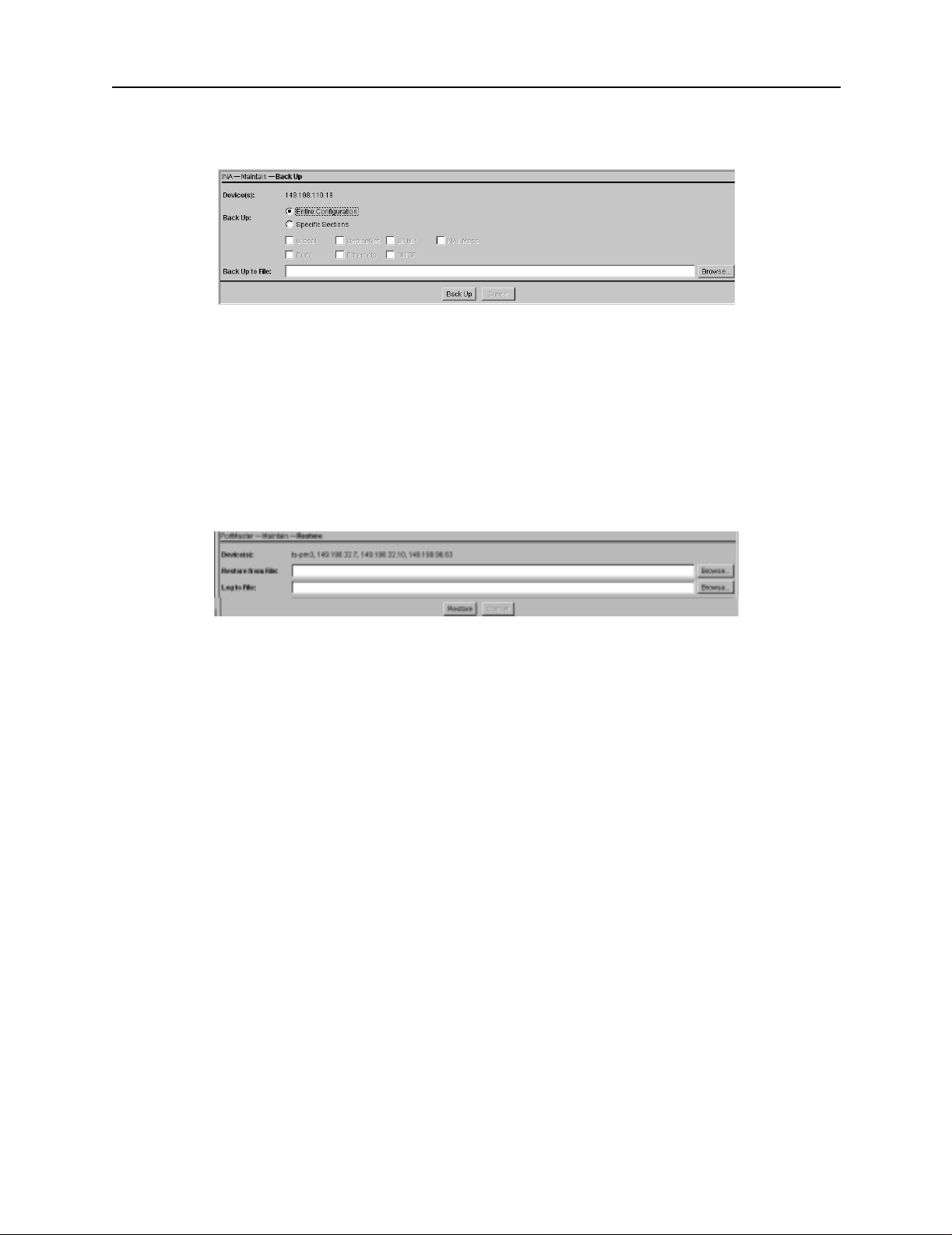
Selecting PMVision Function s
Figure 6-6 PMVision Backup Dialog
Restore the INA Module Settings
To restore the INA module settings captured in a backup file, select
INA→Maintain→Restore. Enter or brow se to the backup filen ame on the Restore
panel (Figure 6-7) and click Restore. The restored values overwrite any values existing
in the INA module. A backup file created with a selective backup overwrites only the
selected configuration values and leaves the others unchanged.
Figure 6-7 PMVision Restore Dialog
6-8 INA Module Installation and Configuration Guide
Page 49

This appendix provide s the following troubl eshooting procedur es for the INA modul e:
• “Observing LED Behavior” on page A-1
• “Observing Boot Messages” on page A-2
• “Using the DS-1 Test Jacks” on page A-5
Additional troubleshooting and maintenance information can also be found in
Appendix C, “MERLIN MAGIX Administration.”
Observing LE D Behavior
Table A-1 identifies LED be havior, possible causes of the behavior, and potential
solutions.
For information on contacti ng Lucent technical support, s ee “Technical Support” on
page -xv.
Troubleshooting A
Tab l e A - 1 Hardware Problems and Solution
LED Behavior Possible Cause Solution
System LED does not ligh t. Power is not presen t. Check that the module is cor rectly
seated in the carrier. Check that the
MERLIN MAGIX system is properly
turned on.
T1/PRI line is connected to
the T1/PRI port a n d th e re d
DS-1 status LED stays lit for
more than 3 0 seconds .
During startup, the system
LED fails to light or stays
continuously lit.
Twenty seconds after
booting, the system LED
stays solidly lit or does not
light.
During operation, the
system LED stays sol idly lit
for more than 20 seconds or
does not light.
The INA module does not
recognize service from the
telephone company.
A hardware proble m has
occurred.
A component might h ave
loosened during sh ipping,
or the module is defective.
A hardware problem mig ht
have been caused by an
external device.
Check the T1 cable and modu lar jack.
If the problem is not resolved, contact
the teleph one com pany.
Contact Lucent technical support.
Contact Lucent technical support.
If the LED stays solidly lit for more
than 20 seconds or does not light after
you have checked all external cables,
contact Lucent technical support.
A-1
Page 50

Observing Boot Messages
Tab l e A - 1 Hardware Problems and Solution (Continued)
LED Behavior Possible Cause Solution
No console login prompt is
displayed.
Ethernet link LED is not lit
when connected to a
10BaseT Ethernet hub.
Network activity LED is
solidly lit.
Terminal settings are
incorrect or a connection or
cable is inoperable.
There is no link integrity. Verify that you have a working
Heavy traffic can cause the
network LED to blink so
rapidly that it appears to be
solidly lit.
However, if packets cannot
be passed, you migh t have
an incorrectly cabled
network.
• Verify terminal sett ings of 9600
baud, 8 data bits, 1 stop bit, a parity
of none, and software control
(XON/XOFF).
• Verify that DIP switch 1 is set to the
right.
• Verify that you have a working null
modem cable and that it is prope rly
connected at both ends. For cable
information see “Console Cable” on
page B-1.
10BaseT cable properly connecte d to
the INA module and to the hu b.
Verify that the network cables are
correctly installed.
Network a c tivity LED i s n o t
lit.
An undefined difficulty
occurred at startup, but the
cause cannot be determined
from LED behavior.
If the INA module is not
receiving or sending traffic,
the network LED is not lit.
Refer to the solution
column.
Observing Boot Messages
If you are having difficulty booting the INA module and are unable to isolate the
problem by observing LED b ehavior, boot the INA module in console mode an d check
the boot messages.
Follow these instructions to check boot messages:
1. At tach a co nsole.
See “Connect a Con sole (Optional) ” on page 3 -3.
Verify that the network cables are
correctly installed.
Try booting in console mode, and
observe the boo t messages. See
“Observing Boot Messages” on page
A-2. If the boot messag es do not
suggest a solution, record the
information and contact Lucent
technical support.
A-2 INA Module Installation and Configuration Guide
Page 51

Observing Boot Messages
2. Press the reboot button.
3. Observe the boot messages displayed on the console screen.
Note – Boot messages vary slightly, depending on the version of the PROM and
ComOS.
The following example is from an INA module:
INA PROM 2.33, 8/19/99
Testing System Clock...OK
Sizing System Memory...4MB FPM
CPU 486DX5-133 +Flash
Starting FLASH Boot...
Flash Memory ... Am29F016 4096K
16384 Verifying Checksum..OK
Starting Loader in flash
Testing High Memory ... . 4096K
INA.
Setting up ACC 2188 PCI Controller
Found 15360K PCI Memory at 0x20000000
Testing PCI Memory block 0x20000000-0x20efffff ...Passed
Total of 15360K PCI Memory Ready
block alloc 425 870400
block_alloc: cpu<0> control 0026ddf0 free_count<425>
Flash Memory 0... Am29F016 4096K
Flash type Am29F016 with 4096K of memory in 64 cells and 4032
nodes
Initializing MT8986 TDM Chip ...Ok
INA ComOS V4.1.5b2.
100R HV=01 FBV=00 FAV=11 FAS=01.
Initializing Rockwell Bt8472 HDLC
Found 3 ports....
e_loopback_test: packet buffer at 200d2080
ether0 active ... PCI-Master
stac_hw_init: Initializing STAC hardware, addr = 0x0ffff800
Hardware compression (9711)
Hardware Compression Enabled
Running ComOS...
PortMaster Console login
A-3
Page 52

Observing Boot Messages
Use Table A-2 to interpret possible diagnostic boot messag es.
Tab l e A - 2 Interpreting Diagnostic Boot Messages
Field Possible Message Explanation
INA PROM N Version number of the
installed boot PROM.
Testing System Clo ck ERROR This error indicate s a boot
failure. Record all
information to this point
and contact Lucent
technical support.
Sizing System Memory ERROR at failed
memory address.
CPU Type 486DX5-133 The type of CPU installed.
Starting FLASH Boot N/A N/A
Flash Memory Am29F016 4096K Nonvolatile RAM brand
16384 16384 Counter for system
Verifying Load Module Che cksum Invalid Length for
Flash at RAM
address.
This error i ndicates a boot
failure. Record all
information to this point
and contact Lucent
technical support.
name and size in kilobytes.
memory dynamic RAM
(DRAM) size. If the size
counter freezes, record all
information to this point
and contact Lucent
technical support.
This error i ndicates a boot
failure. Record all
information to this point
and contact Lucent
technical support.
Starting Load er N/A N/A
Te s t i ng High Memory E R R O R at failed
memory address
A-4 INA Module Installation and Configuration Guide
This error i ndicates a boot
failure. Record all
information to this point
and contact Lucent
technical support.
Page 53

Using the DS-1 Test Jacks
Tab l e A - 2 Interpreting Diagnostic Boot Messages (Continued)
Field Possible Message Explanation
Setting up ACC 2188 PCI Controller
Found 16384K PCI Memory at 0x1ffff000
Testing PCI Memory block 0x200000000x20ffffff ...Passed
Total of 16384K PCI Memory Ready
block alloc 425 870400
block_alloc: cpu<0> control 0028bdb0
free_count<425>
PM3VT/Legend ComOS V4.15.a4. ComOS version string.
100R HV=01 FBV=00 FAV=11 FAS=01 M ER LI N fi rm wa re
Found x ports 3 Number of ports found,
Ether0 active
Running ComOS N/A If the system becomes
PCI-Master Ethernet interface found.
PCI memory has been
correctly set up.
identification.
including C0 and C1.
suspended at this point
and does n ot p rint the ne xt
message, the configuration
nonvolatile RAM
(NVRAM) has been
corrupted. Refer to the
PortMaster Troubleshooting
Guide for instructions o n
nonvolatile RAM recovery.
PortMaster Console login: N/A System is up and running.
Using the DS-1 T est Jacks
The six test jacks provide the means to connect external test equipment to the T1/PRI
line. Table A-3 describes the functions of t he individual jacks. Figure A-1 illust rates the
test jack locations. Figure A-2 shows the test jack configuration.
A-5
Page 54

Using the DS-1 Test Jacks
Tab l e A - 3 DS-1 Test Jacks Description
Test Jack Label Description and Usage
MON In Monitor In. This jack allows externa l test equipment to
MON Out Monitor Out. This jack allows external test equipment to
NET In Network In. An intrusive , break-in jack th at allows external
passively monito r the T1/PRI sign al coming from t he
network to the INA modu le. The use of this jack do es not
disrupt the T1/PRI sign al received by the INA mod ule from
the network.
passively monitor the T1/PRI signal going to the network
from the INA module. The use of this jack does not disrup t
the T1/PRI signal transmitted by the INA module to the
network.
test equipment to inject a T1/PRI signal to the network. The
use of this jack disrupts the T1/PRI signal transmitted by the
INA module to the network .
EQPT Out Equipment Out. An intrusive, break-in jack that allows
external test equipment to intercept and terminate the
T1/PRI signal coming from the INA module. The u se of this
jack disrupts the T1/PRI signal transmitted by the INA
module to the network.
NET Out Network Out. An intrusive, break-in jack that allows
external test equipment to intercept and terminate the
T1/PRI signal comi ng from th e network. The use o f this ja ck
disrupts the T1/PRI signal received by the INA module from
the network.
EQPT In Equipment In. An intrusive, break- in jack that allows
external test equipment to inject a T1/PRI signal to the INA
module. The use of this jack disrupts the T1/PRI signal
received by the INA module from the network.
A-6 INA Module Installation and Configuration Guide
Page 55

Figure A-1 DS-1 Test Jack Locations
Using the DS-1 Test Jacks
M
O
N
M
O
N
N
E
T
E
Q
P
T
N
E
T
E
Q
P
T
Figure A-2 DS-1 Test Jack Configuration
I
N
O
U
T
I
N
O
U
T
O
U
T
I
N
1210-011
A-7
Page 56

Using the DS-1 Test Jacks
A-8 INA Module Installation and Configuration Guide
Page 57

This appendix provides cable and pinout specifications.
Cables Specified
• Console Cable. This null modem cable is use d to connect a terminal or PC to the
console port of the INA module.
• T1/PRI Cable. T his cable is used to connect a T1/PRI line to the INA module.
• Ethernet Interface C abl e. T his cable is used to connect the Ethernet connector on
the INA module to an Ethernet hub.
• Crossover Cable. This cable is used to make a simulated network connection
between the INA mo dule ’s Ethernet port and a free -stand ing co mput er wor kstati on.
Console Cable
Cable Specifications B
Table B-1 shows the ca ble pinouts for a RJ-45- to-DB-25 null mode m cable. The INA
module does not use Data Set Ready (DSR).
Tab l e B - 1 Console Cable Pinout
INA Module
Serial Port (C0)
RJ-45 Name Definition Direction
1 RTS Request to Send Output 5 CTS
2 DTR Data Terminal Ready Out put 8
3 TXD Transmit Data Output 3 RXD
4 GND Signal Ground NC
5 GND Signal Ground 7 GND
6RXDReceive Data Input2 TXD
7 DCD Data Carrier Detect Input 20 DTR
8 CTS Clear to Send Input 4 RTS
2
NC
1. Pins 8 and 6 in the DB-25 connectors are connected internally.
2. Not connected.
Data Set R eady 6
PC or terminal
Serial Port
DB-25
(DTE) Signal
1
2
1
DCD
DSR
B-1
Page 58

T1/PRI Cable
T1/PRI Cable
Table B-2 shows the pinouts for a cate gory 5 unshielded, ungrounded, twiste d pair
cable, as specified by the EIA/TIA-568-B wiring standard, with an RJ-48C connection
Tab l e B - 2 T1/E1 RJ-48C Connector Pinou t
T1 Port
RJ-48C Signal Definition
1 RXD (R ing) Receive Data Input
2RXD (Tip)
4 TX D (Ring) Transmit Data Output
5TXD (Tip)
Direction to or
from the INA
Module
Ethernet Interface
Table B -3 provides specificatio ns for the 10Mbps baseband IEEE 802.3- compa tible
Ethernet interface.
Tab l e B - 3 Ethernet Interface
Ethernet
Type
RJ-48C RJ-48C for 10Base T Category 5
Connector
Type Cable Type
unshielded
twisted pair
Transmission
Distance
Hub distance—328ft (100m) maximum
Repeaters—four maximum
B-2 INA Module Instal lation and Configuration Guide
Page 59

Crossover Cable
This RJ-45 crossover cabl e is used to connect two ( and only two) machines using
10baseT Ethernet without the use of a hub. The cable must be fabricated from category
5 unshielded twisted pair. Table B-4 sho ws the wiring for this cab le.
Tab l e B - 4 Crossover Cable Wiring
RJ-45 Connector RJ-45 Connector
pin 1 pin 3
pin 2 pin 6
pin 3 pin 1
pin 6 pin 2
Crossover Cable
B-3
Page 60

Crossover Cable
B-4 INA Module Instal lation and Configuration Guide
Page 61

MERLIN MAGIX Administration C
This appendix describes t he MERLIN MAGIX sy stem programmi ng options for the INA
module. The INA module is identified as a 100R module in MERLIN M AGIX
programming and consol e displays.
The following topics are cov ered:
• “INA Module System Progr amming Summary ” on page C-1
• “INA Module Administra tion Options” on pa ge C-1
• “INA Module Maintenanc e Options” on page C-3
• “INA Module System Interactions” on page C-7
INA Module System Programming Summary
In general, the INA/100R module supports the same system programming options as the
100D module. Specific exceptio ns and additions are noted in this appendix. Additio ns
include the ability to configure and maintain the internal CSU/DSU support ed by the
100R module. Exceptions include that on ly bipolar 8- zero substit ution (B8ZS) encoding
is supported when the mo dule is used in PRI mod e. For more informati on on 100D
module programming, s ee the System P rogramm ing Manual (555-710-111).
Note – To avoid corruption of data sent and received by the integrated data rou ter,
Lucent recommends tha t all T1/PRI lines used w ith the INA module be provisioned for
B8ZS encoding.
Each 100R module accommodates up t o 23 PRI channels or 24 T1 channels. Each
channel can be either used by the MERLIN MAGIX or assigned to the data router.
Channels assigned to the router can be used for Internet access, remote network
connections, and other WAN applications.
Channels on the 100R module provide the same features and capabilities as channels on
a 100D module. For exa mple, the channels on t he 100R module can be configured as
robbed-bit channels for T1 applications or can be used in B-channel groups for PRI
applications. Channels on the 100R module count towa rds system capacities just as
channels on the 100D mod ule d o. C han ne ls th at ar e assi gn ed t o th e rou ter are inc lude d
in the count. Therefore , the combined total of 100R and 100D modu les in a system
cannot exceed three.
In addition to MERLIN M AGIX system progr amming, the INA modu le requires
programming sp ecifically fo r the router s ubsystem. (S ee “Netwo rk Settings” o n
page 2-2.)
INA Module Administration Options
The INA module introduce s two additional admi nistration options : to activate or
deactivate the onboard CSU and DSU cha nnel selection.
C-1
Page 62

INA Module Administration Options
The rest of the a dministra tion optio ns are ess entially the s ame as for the 100D mo dule.
For more information on configuring the 100D modu le, see System Programming manual
(555-710-111).
Activate or Deactivate the Onboard CSU
The internal CSU on the INA mo dule is activated by d efault. You can view and change
this setting by using the following seq uence on your sy stem programm ing console:
Menu: SysProg→Start→LinesTrunks→More→More→CSU/DSU→Slot#→Enter→
ActivateCSU
Caution – The MER LIN MAGIX is forced into an idle sta te if the CSU settings are
!
changed during active voice calls. In this case, the change in CSU s tatus occurs after a ll
active voice calls have been terminated.
Deactivating the CSU has the following impact on 100R m odule operation:
• The 100R board does not res pond to network initia ted loopback reque sts.
• The 100R board does not se nd T1 performance statistics to the network.
• The line compens ation value u sed by the 100R board corr esponds to the DTE
settings appropriate for a 100D module inste ad of a CSU. The DTE and CSU values
are summar ized in Table C-1
Tab l e C - 1 100R Module Line Compe nsations with a De activated CSU
Line Compensa tion
Setting in MERLIN
MAGIX System
Programming
1 0 to 133 feet 0.0db
2 133 to 266 feet -7.5db
3 266 to 399 feet -15db
4 399 to 533 feet -22.5db
5 533 to 655 feet -22.5db
DSU Channel Selection
By default, no channels are assigned to the router. DSU channel selection is used to
assign channels to the route r. Use the follo wing sequ ence on your syste m pr ogram ming
console to a ssign cha nnels to th e router :
DTE Line Compensation
When CSU Is
DEACTIVATED
CSU Line Bui ldout
(LBO) When CSU Is
DEACTIVATED
Menu: SysProg→Start→LinesTrunks→More→More→CSU/DSU→Slot#→Enter→
ChannelSel→Channel#→Enter
You must repeat this sequence for e ach channel t o be assigned to the router.
C-2 INA Module Installation and Configuration Guide
Page 63

INA Module Maintenance Options
Note – For T1 configurations, you can assign a channel to the router only if the channel
is Unequipped from a switch perspective. For PRI configurations , you can assign a
channel to the router only if the channel is not used in a B channel group or a line pool
on the switch.
Note – For the router to recognize a change in channel assignments, you must reboot
the router either from it s command line interf ace or by pressing the re boot button on
the INA module.
You can view a summary of DSU channel assignments by using the following sequence
on your system programming console.
Menu: SysProg→Start→LinesTrunks→More→More→CSU/DSU→
Slot#→Enter→ChannelSel→Inspect
All channels are listed and marked with one of the selections shown in Table C-2:
Tab l e C - 2 Inspect DSU Channel Assignments
Selection Description
R The channel is assigned to the router.
S The channel is assigned to the switch.
U The channel is assigned to neither the router nor the
switch.
Use the following sequence on your system programming console to unassign channels
from the router.
Menu: SysProg→Start→LinesTrunks→More→More→CSU/DSU→
Slot#→Enter→ChannelSel→Channel#→Delete
You must repeat this sequence for each channel to be unassigned from the router.
INA Module Maintenance Optio ns
The 100R module has im proved T1/PRI err or event report ing and has an expa nded set
of demand tests. All 100D module maintenance options are also included.
Error Events
The INA module provides three additional error event counts as well as the ability to
manually clear these error event counts. Included are
• 24-hour event totals
• Current events
• Selected interval events
• Clearing error events
C-3
Page 64

INA Module Maintenance Options
Note – The additional error event counts are cleared whenever the INA module is reset.
Be sure to view the error events before resetting the module or busying out the module.
From your system programm ing console, use the follow ing sequence to access the INA
module Error Event s screen. Be sure t o select the corres ponding INA modu le slot
number.
Menu: Maintenance→Slot→Slot#→Enter→Error Events
The Current Hour and Previous Hour error event screens that are also used on the 100D
module are available on the INA mo dule. Cleari ng the new er ror event counts does n ot
affect the Current Hour and Previous Hour error event counts. Because the Current
Hour and Previous Hour statistics are computed with a different algorithm, Current
Hour and Previous Hour counts do not match the newer counts.
24 Hour Event Totals
The 24-hour tot al error event screen reports c umulative er ror statist ics spanning th e
past 24 hours. The current even t totals are no t included in this re port. From yo ur
system programming console, use the following sequence to access the INA 24 Hr Total
screen. Be sure to selec t the correspo nding INA module slot number.
Menu: Maintenance→Slot→Slot#→Enter→Error Events→24 hr total
This screen provides s tatistics related to the health of the T1/PRI int erface. These
statistics are summarized in Table C-3.
Tab l e C - 3 24-Hour Total Error Line Items
Item Description
24 Hour Slot xx xx is the slot curre ntly being reported on.
nn Valid
Intervals
MIS Misframes.
SLP Slips.
ES Errored Seconds.
BS Bursty errored seconds
nn is the number of valid historical 15-minute
intervals from the past 24 hours. A valid historica l
interval is one for which data has been captured while
the system was running. During a valid interval, data
has not been lost du e to a cl ea rin g of e rror events or a
board reset. A boar d reset can occu r during a reset,
busy-out, frigid start, cold sta rt or power outage.
.
SEC Severely errore d seconds.
FS Failed seconds.
BPV Bipolar violations.
C-4 INA Module Installation and Configuration Guide
Page 65

Each error statist ic represents th e sum of error even ts from all valid intervals includin g
the current interval. The message “9999” represents an overflow situation.
You can refresh the 24-hour total screen by pressing →Back and then pres sing →24 hr
total again.
Current Events
The Current error ev ent screen rep orts error statis tics for the 15-min ute interval th at is
currently active. The elapsed minutes line displays the number of minutes that have
elapsed for the current int erval. The elapsed m inutes display ran ges from 0 to 15 and is
rounded to the nearest minute. From your system programming console, use the
following sequen ce to access t he Current sc reen. Be sure to select the co rresponding
INA module slot number.
Menu: Maintenance→Slot→Slot#→Enter→Error Events→Current
The events rep orted are t he same as for the 24 hour e vent tota ls screen.
You can refresh the Current screen by pressing →Back and then pressing →Current
again.
INA Module Maintenance Options
Selected Interval Events
The Selected Inte rval Events scre en reports on err or statistics fo r a specific 15-minu te
interval from the pa st 24 hours. Ninety -six 15-minute in tervals occur in a 24-hour
period. Interval 1 is the most recent 15 minute interval just b efore the current interval,
and interval 96 is the oldest interval. Fr om your system pro gramming conso le, use the
following sequence to select a specific interval from the Selected Interval Events screen.
Be sure to select the co rresponding INA module slot numbe r.
Menu: Maintenance→Slot→Slot#→Enter→ErrorEvents→Interval→
Interval#→Enter
Note – Invalid int ervals have all zeroes for err or data, but n o visual indi cation is give n
to show that the interval is not valid. Yo u can, however, compute the total number of
invalid intervals by subtracting the valid interval count on the 24-hour total screen from
96.
Clearing Error Events
The Clear Erro r Eve nts scree n ca uses e rror eve nts fo r all inte rval s, inc luding th e cu rrent
interval, to be cleared. From your system programm ing console, use the fol lowing
sequence to access the Clear Err or Events scre en. Be sure to sele ct the corres ponding
INA module slot number.
Menu: Maintenance→Slot→Slot#→Enter→Error Events→Clear
To stop the clear even t and retain all er ror events, pres s →Back or →Cancel. You will
return to the Error events screen.
C-5
Page 66

INA Module Maintenance Options
Demand Tests
The INA module board i ncorporates three ne w demand tests:
• Line loopback
• Payload loopback
• Bit error rate test (BERT)
Line Loopback T est
The line loopback test loo ps the T1 signal back towards the net work without
regenerating framing and without recalculating a cyclic redunda ncy test (CRC)
checksum. To perform this test, you must first busy out the I NA module. From your
system programmi ng console, us e the followin g sequence to start the li ne loopback t est:
Menu: Maintenance→Slot→Slot#→Enter→Demand test→LineLpbk
After the line loopback test has been started , selecting →Back terminates the test.
Note – During the line loopback te st, the INA module tran smit clocking is derived from
the signal received by the I NA module. The remote e nd of the T1 connection mu st be
set up as the clock master for the T1/PRI inrfco v(o)6.5il tilcloo
C-6 INA Module Installation and Configuration Guide
Page 67

INA Module System Interactions
Table C-4 desc ribes the availa ble BERT test patte rns.
Tab l e C - 4 BERT Test Patterns
Test Options Description
→QRSS Produces a quas i-random t est pattern .
→3 in 24 Produces a bit pattern consisting o f 3 ones in 24
(1000 1000 1000 0000 0000 0000).
→All zeroes Produces a test pattern of all zeroes.
→All ones Pr oduces a test pattern of all on es.
After starting a BERT test, press →Monito r to view the progress of the test. One of the
following results will be display ed.
• No Synch—Indicates that the BERT test pattern is not being successfully received
back.
• Sync-Errors—Indicates that the BERT test pattern is being successfully received.
The console displays the num ber of bit error detecte d. For overflow situa tions
“99999” is displayed.
To refresh the disp lay, press →Back, and then select →Monitor. This refreshes the test
results without te rminating the test.
Note – During BERT testing , the INA module transm it clocking is deriv ed from the
backplane of the MERLIN M AGIX. The remo te en d of the T1 connectio n must be set u p
as either the cl ock slave for th e T1/PRI inter face, or mu st provide a lin e loopback.
INA Module System Interactions
Backup and Restore
Like the 100D module, an y programming done o n the MERLIN MAGIX fo r the INA
module can be backed up an d restored wit h the system Person al Computer Me mory
Card International As sociation (PCM CIA) card or by a PC ru nning WinSPM. The new
administration options f or the INA module (CSU Act ivate/D eactivate and DSU Chann el
Selection) are included.
Note – Administr ation dat a associat ed with t he route r is not backe d up and rest ored by
the MERLIN MAGIX backup functions. Router administration data must be backed up
and restored separa tely by using PMVision (see C hapter 6, “Using PM Vision”). The
INAWizard may be used to restore the basic network settings, but is not a true backup.
(See Chapter 4, “Using the I NAWizard”.)
Surrogate Oper ation
The INA module supports su rrogate mode progr amming. The INA modu le is indicated
on MERLIN MAGIX system program ming screens by the label 100R-U.
C-7
Page 68

INA Module System Interactions
Board Renumbering
The INA module works in the s ame manner as the 100 D module for board
renumbering. Use boa rd renumbering to re place a 100D module with a 100R module,
and vice versa. After the board renumbe ring, T1/PRI data that had been previou sly
administered for the replaced module is associated with the new module. The data
channels assigned to the 100R are now be unassigned on the 100D module.
Print Reports
The System Inventory Report is enhanced to include summary information about INA
modules present in the system. This summary information is pr esented under the
100-RU label.
PCMCIA Flash Memory Card-Based Upgrade Operation
The INA module firmware is upgradeable using the MERLIN MAGIX PCMCIA card.
Note – Performing an upgrade to the INA module firmware using the MERLIN MAGIX
PCMCIA card does n ot upgrade the INA mo dule router so ftware. Router so ftware is
upgraded separately with the PMVision application. Depending upon the nature of the
upgrade, either a INA module firmware upgrade, or a router software upgrade, or both
might be required.
Other System Interactions
Table C-5 shows sys tem conditions applyi ng to the INA module.
Tab l e C - 5 INA Module System Interactions
Condition Explanation
Idle Conditions -
System Forced
Idle
Slot Busy-Out An INA module can be busied out even if the
The system migh t be forced i nto an idle state
while the module is routing data traffic. When
the system is in the forced idle condition, the
router on the INA module continues to operate
and route data traffic.
module is routing data traffic. Busying out the
module disrupts both voice and router services.
Voice and data services are restored when the
module is restored.
C-8 INA Module Installation and Configuration Guide
Page 69

Tab l e C - 5 INA Module System Interactions (Continued)
Condition Explanation
INA Module System Interactions
System Erase
(Frigid Start)
System Restart
(Cold Start)
War m S ta r t All the programming for the INA module is saved
Board
Replacement
When a frigid start occurs, all MERL IN MAGIX
parameters for the INA module are returned to
default values. Router administration data,
however, is preserved. MERLIN MAGIX
parameters must be reprogrammed after the
frigid start to restore v oice and dat a services. The
router must be rebooted after DSU channel
selection has been performed.
All programming for the INA module is saved
during a cold start. Voice and router services are
disrupted for the duration of the cold start but
are restored aft er the cold sta rt.
during a warm start.
You must turn the power off on the MERLIN
MAGIX before replacing an INA module. The
INA module is not hot-swap pable.
C-9
Page 70

INA Module System Interactions
C-10 INA Module Installation and Configurat ion Guide
Page 71

Index
Numerics
100D module C-1
operation
renumbering boards
24-hour event totals
2-2
C-8
C-4
A
activate or deactivate CSU 2-1, C-2
administration options
administrative password
C-1
5-2
B
B8ZS encoding 2-1, C-1
backup
INA module settings
MERLIN MAGIX settin gs
BERT
C-6
6-7
C-7
bipolar 8-zero substitution. See B8ZS
bit error rate test (BERT)
C-6
boards
renumbering
replacement
C-8
C-9
boot messages
checking
interpreting
boot mode, configuring
A-2
A-4
3-3
BOOTP 3-3
broadcast address, setting
5-3
C
C0 port
location
using
C1 serial port
location
using for console session
cables
connecting
console
crossover
Ethernet
passthrough
1-3
5-1
1-2
5-2
3-1
3-3, B-1
B-3
3-4, B-2
3-1
specifications
T1/PRI
caution icon
channel rate, setting
B-1
3-3, B-2
xiv
2-3, 5-6, 6-6
channels
assigning
setting
2-2, C-2
5-6
channel service unit. See CSU
code supression, B8ZS
cold start
C-9
2-1, C-1
command line interface
description
using
1-2
5-1
configuration
console port
getting information
parameters
1-4
steps
configuration displays, PMVision
configuration functions, PMVision
configuration panels, PMVision
3-2
2-1
2-3
6-5
6-4
6-4
connecting
console
Ethernet cable
INAWizard workstation
PMVision workstation
serial passthrough cable
T1/PRI Cable
3-3
3-4
4-1
6-1
3-1
3-3
console
B-1
cable
checking messages
configuring port
connecting
3-3
A-2
3-2
console port. See C0 port console session
console session
C1 serial port
passthrough serial connec tion
5-2
Telnet
using C0 port
5-2
5-2
5-1
contact information
Lucent technical support
mailing lists
xv
conventions in this guide
xv
xiv
crossover cable
Index-1
Page 72

Index
pinout B-3
PMVision
6-2
CSU
activate or deactivate
line buildout
CSU/DSU
current events
1-1
C-5
C-2
2-1, C-2
D
data channels
description
first channel assi gned
unassigning
1-1
2-3
C-3
data link connection identifier. See DLCI settings
data service unit. See DSU
deleting data channels
demand tests
C-6
destination address
DHCP settings
2-4
diagnostic messages
C-3
5-7
A-4
DIP switch
boot mode
location
setting
DLCI settings
document advisory
3-2
1-3
3-2
2-3, 5-7, 6-6
xiv
documentation
MERLIN MAGIX
PortMaster
document conventions
domain name
5-5
xi
xiii
xiv
DS-1 LEDs
front panel location
observing
3-4
1-2
DS-1 test jacks
location 1-4, A-7
A-5
using
DSU
channel assi gnm en ts
channel selection
C-3
2-1, C-2
Dynamic Host Connection Protocol. See DHCP
settings
E
electrical shock risk ix
error events
24-hour event totals
clearing
C-5
C-4
current events
selected interval
C-5
C-5
Ethernet
B-2
cable
connecting cable
3-6
LEDs
3-4
Ethernet activity LED
location
observing
Ethernet interface
location
specifications
1-3
3-6
B-2
1-4
B-2
Ethernet link LED
location
observing
1-4
3-6
F
filters, on WAN port 5-7
fire risk
ix
Frame Relay. See protocol, WAN port.
frigid start
front panel
functions, PMVision
C-9
1-2
6-4
G
gateway 2-3, 5-4, 6-6
H
hostname resolution 5-4
hot-swappability
C-9
I
idle conditions C-8
INA module
administration
administration options
basic settings
board renumbering
command line interface connection
description
front panel
INA wizard connection
installation
maintenance options
overview of installation and configuration
PMVision connection
replacement
1-1
C-1
2-3, 6-5
C-8
1-1
1-3
4-1
3-1
C-3
4
6-1
C-9
5-1
1-
Index-2 INA Module Installation and Configuration Guide
Page 73

Index
system interactions C-7
system programming sum mary
INAWizard
description
installation
operation
system requirements
inawizard_install.exe
1-2
4-1
4-2
4-1
4-1
INAWizard workstation
connection with crossover cable
LAN connection
injury risk
ix
4-1
installation
INA module
INAWizard
PMVision
1-4
steps
3-1
4-1
6-1
IP address, Ether0
broadcast
network
5-3
2-3, 5-3, 6-5
IP address, W0
destination
local
IPX
5-3
2-3, 5-6, 6-6
2-3, 5-7, 6-6
C-1
4-2
assign channe ls c om m an ds
programming summary
2-2, C-2
C-1
messages on the console
checking
interpreting
A-2
A-4
N
name service 2-3
NAT settings
2-4
netmask
Ether0
W0
2-3, 6-6
6-6
network activity LED
location
1-3
network address
setting
5-3
network address tran slat i on. Se e NAT
network parameters
note icon
xiv
2-2, 6-5
O
observe LED behavior 3-4
L
LAN connection
INAWizard
PMVision
4-1
6-1
LEDs
3-4
DS-1
Ethernet
3-6
observing for troubleshooting
system
T1/PRI
line loopback test
3-5
3-4
C-6
link LED
location
observing
local WAN port address
5-2
login
1-4
3-6
2-3, 6-6
M
mailing lists, subscribing to xv
maintenance options
MERLIN MAGIX
setup T1/PRI
software upgrade
MERLIN MAGIX adminis tra tio n
C-3
2-1
C-8
A-1
P
parameters, basic configuration 2-3, 5-3, 6-5
passthrough serial connec tion
3-1
cable
5-2
using
payload loopback test
PCMCIA upgrade C-8
PMVision
adding WAN ports with
backup function
basic settings
communicating with INA
configuration displays
configuration functions
configuration panels
connect workstation
description
1-2
entering settings with
installation
LAN connection
restore function
running
6-2
selecting functions
setting WAN ports
system requirement s
6-1
using
C-6
6-7
6-7
6-5
6-3
6-5
6-4
6-4
6-1
6-5
6-1
6-1
6-8
6-4
6-7
6-1
Index-3
Page 74

Index
Point-to-Point protocol. See protocol, WAN port
PPP. See protocol, WAN port
precautions, safety
print reports
protocol, WAN port
ix
C-8
2-3, 5-7, 6-6
R
reboot button, location 1-4
removing data channels
renumbering boards
reports
C-8
C-3
C-8
restoring
INA module settings
MERLIN MAGIX settin gs
running PMVision
6-8
C-7
6-2
S
safety instructions ix
selected interval events
serial passthrough
connecting
using
3-1
5-2
set administrative passw ord
set broadcast address
set channel rate
5-6
set default route gate wa y
set DIP switch 1 to the rig ht.
set DIP Switches
set domain
3-2
5-5
set Ether0 broadcast
set Ether0 netmask 5-3
set gateway
5-4
set line0 channels
set nameserver 5-5
set namesvc
set system name
5-5
5-4
settings
INAWizard
2-3
using PMVision for
set W1 address
5-7
set W1 destination
set W1 netmask
5-7
set W1 protocol 5-7
set W1 speed
slot busy out
5-6
C-8
SPM. See WinSPM
C-5
5-2
5-3
5-4
3-2
5-3
5-6
6-5
5-7
subnet mask
support, technical
5-3, 5-7
xiv, xv
surrogate operation C-7
system erase
system interactions
C-9
C-7, C-8
system LED
location
observing
system name
1-3
3-5
2-3, 5-4, 6-6
system requirement s
INAWizard
PMVision
4-1
6-1
system restart C-9
T
T1/PRI
all unequipped
assign channe ls
assigning chann el s
B-2
cable
connector location
3-4
LEDs
MERLIN setup
provisioning information
unequipped
tables, configuration
technical support
telnet console session
2-2, C-2
2-2, C-2
2-2
1-4
2-1
2-1
2-2, C-2
6-5
xv
5-2
test jacks, DS-1
location
using
1-4, A-7
A-5
tests
C-6
BERT
line loopback
payload loopback
C-6
C-6
training
INA module
PortMaster
xv
xv
transport protocol. See protocol, WAN port
troubleshooting INA module
A-1
U
unassigning data channels C-3
using INAWizard
4-1, 6-1
using WinSPM 5-2
V
voice channels, description 1-1
Index-4 INA Module Installation and Configuration Guide
Page 75

W
WAN port
additional
channel rate
filters
protocol
rebooting
setting
setting with PMVision
warm start
warning icon
warranty
WinSPM
passthrough option
utility
wizard. See INAWizard
2-2
2-3, 5-6
5-7
5-7
5-6
5-5
C-9
xiv
xv
1-1
Index
6-7
5-1, 5-2
Index-5
 Loading...