

Page 1

MERLIN LEGEND
®
Communications System
Release 7.0
System Manager’s Quick Reference
555-670-119
Comcode 108370321
Issue 1
April 1999
Page 2

Copyright © 1999, Lucent Technologie s Document 555-670-1 1 9
All Rights Reserved Comcode 108370321
Printed in USA Issue 1
April 1999
Notice
Every effort has been made to ensure that the information in this guide is complete and accurate at the time of printing.
Information, however, is subject to change. See
Appendix A, “Customer Support Information,” in
System Programming
for important information.
Your Responsibility for Your System’s Security
Toll fr aud is the unauthorized use of your telecommunications system by an unauthorized party—for example, persons
other than your company’s employees, agents, subcontractors, or persons working on your company’s behalf. Note
that there may be a risk of toll fraud associated with your telecommunications system, and, if toll fraud occurs, it can
result in substantial additional charges for your telecommunications services.
You and your system manager are responsible for the security of your system, such as programming and configuring
your equipment to prevent unauthorized use. The system manager is also responsible for reading all installation,
instruction, and system administration documents provided with this product in order to fully understand the features
that can introduce risk of toll fraud and the steps that can be taken to reduce that risk. Lucent Technologies does not
warrant that this product is immune from or will prevent unauthorized use of common-carrier telecommunication
services or facilities accessed through or connected to it. Lucent Technologies will not be responsible for any charges
that result from such unauthorized use. For important information regarding your system and toll fraud, see Appendix A,
“Customer Support Information,” in
System Programming
.
Federal Communications Commission Statement
This equipment has been tested and found to comply with the limits for a Class A digital device, pursuant to Part 15 of
the FCC Rules. These limits are designe d t o provid e reas ona bl e pro tect ion aga i nst har mfu l inte rfe ren ce when the
equipment is operated in a commercial environment. This equipment generates, uses, and can radiate radio frequency
energy and, if not installed and used in accordance with the instruction manual, may cause harmful interference to radio
communications. Operation of this equipment in a residential area is likely to cause harmful interference, in which case
the user will be required to correct the interference at their own expense. For further FCC information, see Appendix A,
“Customer Support Information,” in
System Programming
.
Canadian Department of Communications (DOC) Interference Information
This digital apparatus does not exceed the Class A limits for radio noise emissions set out in the radio interference
regulations of the Canad ian Department of Communications.
Le Présent Appareil Numérique n’émet pas de bruits radioélectriques dépassant les limites applicables aux appareils
numériques de la classe A préscrites dans le réglement sur le brouillage radioélectrique édicté par le ministère des
Communications du Canada.
Page 3

Year 2000 Compliance
The MERLIN LEGEND Communications System is certified to be Year 2000 compliant. Additional information on this
certification, and other issues regarding Year 2000 compliance, is available online at
http://www.lucent.com/enterprise/sig/yr2000.
Trademarks
5ESS, AUDIX, CONVERSANT, CentreVu, DEFINITY, Magic On Hold, MERLIN, MERLIN LEGEND, MERLIN Mail,
PART NER, PassageW ay, MLX-10, MLX-10D, MLX-10DP, MLX-16DP, MLX-20L, MLX-28D, MLS-6, MLS-12, MLS-12D,
MLS-18D, MLS-34D, SYSTIMAX, TransTalk, and Voice Power are registered trademarks and 4ESS, Intuity, Lucent
Technologies, and Prologix are trademarks of Lucent Technologies in the US and other countries.
Acculink, ACCUNET, MEGACOM, MulitiQuest, MLX-5, MLX-5D, and NetPROTECT are registered trademarks of
AT&T.
Microsoft, Windows, Windows NT, and MS-DOS are registered trademarks of Microsoft Corporation.
ProComm and ProComm Plus are registered trademarks of DataStorm Technologies, Inc.
Supra, Supra NC, StarSet, and Mirage are registered trademarks of Plantronics, Inc.
UNIX is a registered trademark of UNIX System Laboratories, Inc.
PagePac is a registered trademark and Powermate and Zonemate are trademarks of DRACON, a division of Harris
Corporation.
Okidata is a registered trademark of Okidata Corporation.
Pipeline is a trademark of Ascend Communications, Inc.
Intel and Pentium are registered trademarks of Intel Corporation.
Apple and Macintosh are registered trademarks of Apple Computer, Inc.
IBM is a registered trademark of International Business Machines, Inc.
Novell and NetWare are registered trademarks of Novell Corporation .
CLASS is a servicemark of Bellcore.
Page 4

Ordering Information
0
Call: BCS Publications Center
Write: BCS Publications Center
Order: Document No. 555-670-119
For more information about Lucent Technologies documents, refer to the section entitled “Related Documents” in
“About This Guide” in
Voice 1-800-457-1235 International Voice 317-322-6791
Fax 1-800-457-1764 International Fax 317-322-6699
2855 North Franklin Road
Indianapolis, IN 46219-1385
Comcode: 108370321
Issue 1, April 1999
System Programming
.
Support Telephone Number
In the continental US, Lucent Technologies provides a toll-free customer helpline 24 hours a day. Call the Lucent
Technologies Helpline at 1-800-628-2888 or your Lucent Technologies authorized dealer if you need assistance when
installing, programming, or using your system. Outside the continental US, contact your local Lucent Technologies
authorized representative.
Network Engineering Group
For assistance in designing a private network, call the Network Engineering Group at 1-888-297-4700.
Lucent Technologies Corporate Security
Whether or not immediate support is required, all toll fraud incidents involving Lucent Technologies products or services
should be reported
Lucent Technologies Corporate Security is available for consultation on security issues, investigation support, referral
to law enforcement agencies, and educational programs.
to Lucen t Technologies Corporate Security at 1-800-821-8235. In addition to recording the incident,
Lucent Technologies Fraud Intervention
If you
suspect y o u are being victimiz ed
Service Assistance Center at 1-800-628-2888.
by toll fraud and you need technical support or assistance, call BCS National
Warranty
Lucent Technologies provides a limited warranty on this product. Refer to “Limited Warranty and Limitation of Liability”
in Appendix A, “Customer Support Information,” of
System Programming
.
Page 5

MERLIN LEGEND
®
Communications System Release 7.0
System Manager’s Quick Reference
System Information Sheet
If you have a problem with your system, you may be able to resolve it quickly and easily by
following the approp riate trou bleshoot ing proced ure in this gui de. If the problem pe rsists or is
not listed in this guide, call the Lucent Technologies Helpline at 1-800-628-2888 for further
assistance; consultation charges may apply.
When you call the Helpline, the Lucent Technologies representatives can better help you if
you have available the following system information and troubleshooting information. Also,
obtain system planning Form 2a, System Numbering: Extension Jacks, and
Form 2c, System Numbering: Line/Trunk Jacks.
System Information
Company Name (as on equipment order)
Account Number (if known)
Customer Identification Number
Main Listed Telephone Number (for this
location)
Lucent Technologies Contact Name and
Telephone Number
0
Troubleshooting Information
Type of equipment experiencing the problem (for example, MERLIN LEGEND
Communications System, MERLIN LEGEND Mail, or a particular system component).
Page 6

0
System Information Sheet—
Continued
A description of the problem:
Has this problem occurred before?
Have you attempted to troubleshoot the problem?
Page 7

MERLIN LEGEND Communications System R7.0
System Manager’s Quick Reference
Contents
555-670-119
Contents
Contents vii
Getting Started 1
■ Welcome 1
■ System Overview 1
Incoming Trunks 3
Modes of Operation 5
System Components 8
Line/Trunk and Extension Modules 10
Auxiliary Equipment 17
Features 20
Applications 26
System Capacities 28
Issue 1
April 1999
vii
Related Documents 37
■ Programming Overview 39
Types of Programming 39
Methods of Programming 41
Summary Programming Pr oc edu re s 41
Managing the System 43
■ Overview 43
■ Starting and Ending System Programming 44
Displaying the System Programming Menu 44
About Moving Among System Programming Screens 44
Exiting System Programming 45
■ Setting Basic System Operating Conditions 46
Setting System Date 46
Setting System Time 46
Page 8

MERLIN LEGEND Communications System R7.0
System Manager’s Quick Reference
Contents
555-670-119
Backing Up the System 47
■ Performing Centralized Teleph one Pr og ra mming 48
Programming Features onto a Single Telephone 49
Copying Feature and SA/ICOM Buttons 49
Copying Line/Trunk Button Assignments 50
■ Managing Telephones 52
Adding/Removing an Extension 52
Single Renumbering 54
Block Renumbering 54
Assigning/Unassigning Trunks or Pools to Extensions 55
Assigning/Unassigning ICOM or SA Buttons 55
Programming for Tip/Ring on 412 LS-ID-ETR and
016 ETR Modules 56
Identifying Analog Multiline Telephones without BIS or
HFAI Capability 57
Issue 1
April 1999
viii
Identifying Analog Multiline Telephones for the Voice
Announce Feature 58
Identifying Analog Multiline Telephones at Data
Workstations 58
Moving an Extension 59
Assigning a HotLine Extension 59
Changing Calling Restrictions 60
Changing Trunk-to-Trunk Transfer Status 60
Changing Coverage Delay Rings 61
Adding/Removing a Line 62
Managing the DLC and QCC Operator Positions 63
Assigning a DLC Operator Position 63
Assigning a QCC Operator Position 63
Assigning QCC Operator to Receive Calls 64
Page 9

MERLIN LEGEND Communications System R7.0
System Manager’s Quick Reference
Contents
555-670-119
Assigning QCC Queue Priority Level 65
Adding Optional Operator Features 65
Setting Operator Hold Timer 66
Enabling the DLC Operator Automatic Hold 67
Programming Hold Return 67
Programming Automatic Hold or Release 68
Setting Queue over Threshold 68
Programming Elevate Priority 68
Programming Calls-In-Queue Alert 69
Programming a QCC Operator to Receive Call Types 69
Assigning QCC Call Type Queue Priority Level 70
Enabling Voice Announce 71
Programming for Message Center Operation 71
Programming for Extended Call Completion 72
Issue 1
April 1999
ix
Setting Return Ring 72
Programming for Position Busy Backup 73
Connecting Auxiliary Equ ipm ent 73
Programming for Music-On-Hold 74
Programming for Loudspeaker Paging 74
Programming for Fax Machines 75
Programming for Maintenance Alarms 76
Programming for Voice Messaging System and
Automated Attendant 77
Managing Group Features 78
Changing Group Calling Member Assignments 78
Changing Group Coverage Member Assignments 78
Managing Lists 79
Revising an Allowed List 79
Page 10

MERLIN LEGEND Communications System R7.0
System Manager’s Quick Reference
555-670-119
Contents
Assigning an Allowed List to Extensions 80
Revising a Disallowed List 80
Assigning a Disallowed List to Extensions 81
Managing Night Service Featur es 81
Revising Night Service with Group Assignments 81
Revising Night Service with Coverage Control 83
Changing Labels 83
Changing Extension Directory Labels 84
Changing Trunk Labels 84
Changing Posted Message Labels 85
Changing Calling Group Labels 85
Changing System Speed Dial Labels 86
Managing CTI Links 86
Printing a System Information Report 87
Issue 1
April 1999
x
Busying Out the MLX Module 87
Adding a CTI Link 88
Removing a CTI Link 88
Restoring the MLX Module 88
About Reports 89
■ Overview 89
■ Printing SMDR Reports 92
■ Printing System Programming Reports 93
Troubleshooting the System 95
■ Overview 95
■ All Telephones Are Dead (No Dial Tone or Lights) 97
■ Some Telephones Are Dead (No Dial Tone or Lights) 98
■ Difficulty Making Outside Calls 103
Page 11

MERLIN LEGEND Communications System R7.0
System Manager’s Quick Reference
555-670-119
Contents
■ Telephone Does Not Ring 108
■ DLC Not Ringing for Incoming Calls 112
■ QCC Not Ringing for Incoming Calls 114
■ Single-Line Telephones Ring Back after Completed Call 117
■ Cannot Transfer Call after Answer on an Outside Line 118
■ Night Service Not Working 120
■ Calls Not Going to Voice Mail 123
■ Callers Receiving Incorrect Response from Voice Mail 128
■ Calls Not Going to Coverage 130
■ Trouble Hearing Called Party 132
■ Programmed Button Fail s 134
■ Reminder Messages Received with the Wrong Time 136
■ Recall/Switchhook Does Not Work 137
■ Calling Group Members Not Receiving Calls 139
Issue 1
April 1999
xi
■ Calls Not Receiving Screen-Pop 142
■ Calling Group Overflow Calls Not Receiving Screen-Pop 145
■ Secondary Announcements Not Playing as Programmed 146
■ On 016 MLX Module, Ports 1–8 Work, but Ports 9–16 Do Not 151
■ Other or Unresolved Problems 152
Page 12

MERLIN LEGEND Communications System R7.0
System Manager’s Quick Reference
Contents
555-670-119
Issue 1
April 1999
xii
Page 13

MERLIN LEGEND Communications System R7.0
MERLIN LEGEND Communications System R7.0
System Manager’s Quick Reference
System Manager’s Quick Reference
Getting Started
Welcome
555-670-119
Issue 1
April 1999
1 Getting Started
Welcome
This quick reference is designed to help you administer the MERLIN LEGEND®
Communications System. It provides summary programming procedures for
everyday tasks you perform in order to manage your system.
Issue Issue 1
April 1999
1
Prior to using this guide, you should become familiar with
which provides detailed programming procedures for tasks in this quick
reference as well as for all programming tasks that can be performed for the
system.
This chapter provides a system overview that describes the major aspects of the
system and a programming overview that explains the types of programming
available for the system, as well as the methods available to implement the
programming.
System Programming
System Overview
The MERLIN LEGEND Communications System is a switch located on a
company’s premises, providing access to powerful features and advanced
telephone network applications and services. The system can handle voice and
data calls simultaneously, and voice features can enhance the use of data
communications. The system accommodates businesses with needs ranging
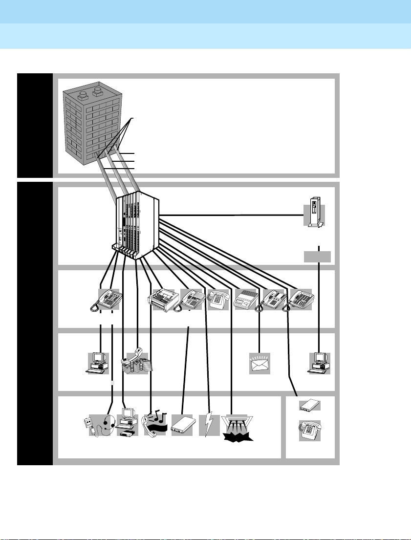
from a few telephones up to 200 telephones. Its modular design allows easy
expansion. The following figure illustrates a MERLIN LEGEND Communications
System connected to telephones, applications, and auxiliary equipment.
,
Page 14
MERLIN LEGEND Communications System R7.0
System Manager’s Quick Reference
555-670-119
Getting Started
System Overview
.
Telephone Company
Central Office
(CO)
Issue 1
April 1999
2
Telephone
Company
MERLIN
LEGEND
MERLIN
LEGEND
Communications
System
Control Unit
Telephones
and Other
Equipment
Applications
PassageWay
Direct Connection
Solution
Auxiliary
Components
Headset
Building A
MLX
Telephone
Incoming Trunks
Loopstart Trunk
Groundstart Trunk
Digital Facility
)
/
L
s
s
T
e
e
A
n
n
i
(
o
L
s
h
e
e
p
n
d
e
i
l
o
s
e
t
h
T
u
p
)
l
e
O
l
a
e
t
i
S
T
S
g
L
i
g
L
r
/
D
o
o
X
l
(
S
2
L
a
S
1
X
G
n
M
0
L
G
A
8
4
8
M
0
8
8
4
0
4
8
0
0
4
PROCESSOR
P
O
W
E
R
C
A
U
T
I
O
N
O
N
O
F
F
T
u
r
n
o
f
f
p
o
w
e
r
b
i
n
e
s
f
o
e
r
r
e
t
i
n
r
g
e
o
m
r
o
v
i
n
m
g
o
d
u
l
e
s
A
G
I
N
P
U
T
F
R
G
N
D
Call
Accounting
System
E
X
P
R
E
S
S
R
O
U
T
E
D
i
g
i
t
a
l
A
d
a
p
t
e
r
1
0
0
0
D
a
t
a
Computer
Music-On-Hold
and ISDN
Terminal
Magic On Hold
Adapter
Machine
O
H
or
LAN
Telephony
Server
Your LAN
Fax
MLX
Telephone
with MFM
Single-
Line
Phone
Answering
Machine
Messaging
Voice
System
Analog
Multiline
Telephone
MLS/ETR
Telephone
Application
CTI Link
OPRE
L
D
Modem,
Uninterruptible
Fax,
Bell, etc.
Power
Supply
“Attention”
Paging
System
Single-
Line Phone
Building B
System Overview
Page 15

MERLIN LEGEND Communications System R7.0
System Manager’s Quick Reference
Getting Started
System Overview
555-670-119
Issue 1
April 1999
Incoming Trunks
Trunks are the telephone company’s facilities, provided by the central office to
carry voice and/or data communications. There are a variety of trunks, each with
different capabilities, as described in the following table.
Incoming Trunks
Trunk Ty pe Description
Loop-Start Provides incoming and outgoing calls and are intended primarily
for key systems and older PBXs. They are the simplest (often
the least expensive) and most common facilities in the
nationwide telephone network. Although they are not appropriate
for some situations, they are necessary for others (for example,
some caller identification services).
Ground-Start Provides a signal at the beginning and end of incoming and
outgoing calls to determine the availability of a trunk before the
central office routes an incoming call on it. Also, when either the
caller or the called party hangs up, the entire circuit is
disconnected and dropped.
3
Tie Provides private lines that directly connect two communications
systems. Using a tie trunk, a user on one system can call an
extension on another system by dialing an access code and the
extension number or simply the extension number. In Release
6.0 and later systems (Hybrid/PBX mode only), tandem tie
trunks, either analog or T1-emulated, can be used for
networking. In this case, the user dials only the non-local
extension number without an access code. In more complex tie
trunk configurations, a person can tie into another system and
use a trunk that does not exist on his or her own system.
Direct Inward
Dial (DID)
Provides fast access to specific individuals; incoming DID calls
can be routed directly to an extension or calling group without
system operator assistance.
Page 16

MERLIN LEGEND Communications System R7.0
System Manager’s Quick Reference
Getting Started
System Overview
Incoming Trunks — Continued
555-670-119
April 1999
Trunk Ty pe Description
T1 In T1 voice operation, a line can be programmed through the
system, without the services of a telephone company installer, to
emulate a ground-start, loop-start, tie, or DID trunk. T1 operation
also gives you access to special services, such as inbound 800
or WATS service for incoming, toll-free service for voice calls.
T1 data operation allows high-speed data communications over
the public switched network; this is called
service
. It also provides data tie lines to connect one MERLIN
T1 Switched 56
LEGEND Communications System to another or to a DEFINITY
system. A T1 data operation line is called a channel.
Issue 1
4
Primary Rate
Interface
(PRI)
Basic Rate
Interface
(BRI)
A digital facility that provides the equivalent of 24 lines, called
channels, 23 of which are B-channels. Each B-channel can
dynamically provide voice and data services; one D-channel
carries signaling information for the 23 B-channels.
A digital facility that provides the equivalent of 3 lines, called
channels, 2 of which are B-channels. Each B-channel can
dynamically provide voice and data services; one D-channel
carries signaling information for the 2 B-channels.
Page 17

MERLIN LEGEND Communications System R7.0
System Manager’s Quick Reference
Getting Started
System Overview
555-670-119
Modes of Operation
The system operates in one of three modes:
• Key Mode. The simplest way to provide people with more than one line
from a telephone. Easy to use. Recommended for smaller systems.
• Hybrid/PBX Mode. Especially useful where toll fraud/security are a
concern. Provides cost-effective call routing, especially useful for
special-purpose network services. Recommended for medium to larger
systems.
• Behind Switch Mode. Used when the system is connected to a system
such as DEFINITY. May be appropriate for users who are part of a large
organization—for example, a department within a company.
The following table outlines the primary differences among the modes.
Modes of Operation
Behind Sw it c h
Key Mode Hybrid/PBX Mode
Mode
Issue 1
April 1999
5
Description Telephones have
multiple buttons
(or keys) labeled
with telephone
numbers.
Every button
corresponds
directly to an
outside line.
Different buttons
(ICOM buttons)
are used for inside
calls.
Outside trunks are
grouped in pools
for shared use; the
system
automatically
selects an
available outside
trunk.
People use the
same button to
make both inside
and outside calls.
Used when the
system (called the
local system) is
connected to a
larger PBX or
Centrex system
(called the host
system).
One outside line (a
prime line) is
assigned to each
telephone. The host
system provid es the
interface to outside
lines and some
features.
Page 18

MERLIN LEGEND Communications System R7.0
System Manager’s Quick Reference
Getting Started
System Overview
Modes of Operation — Continued
555-670-119
Key Mode Hybrid/PBX Mode
Issue 1
April 1999
6
Behind Sw it c h
Mode
Types of Trunks Ground-start
Loop-start
Tie
DS1 (T1 only)
BRI
Number of
Extensions:
Fewer than 50
More than 50
Types of
Buttons
Good
Not recommended
A line button for
each outside line.
Up to 10 ICOM
buttons for inside
calls.
Ground-start
Loop-start
Tie
DS1 (PRI and T1)
DID
BRI
Private network
trunks (Release
6.0 and later)
Good
Good
Up to 10 SA
buttons.
Pool button(s) to
access a specific
pool(s). (Optional)
A personal line
button for
dedicated use of a
specific outside
trunk.
Ground-start
Loop-start
Tie
Good
Good up to 80
For multiline
phones:
Multiple prime line
buttons. Up to 10
ICOM buttons.
User Access to
Outside
Lines/Trunks
Types of
Operator
Consoles
Choosing a
specific line button
Dialing a code
(usually 9) from an
SA button
DLCs only DLC, QCC, or a
combination of
both
Dialing the host
system’s dial-out
code (usually 9)
from a prime line
button.
DLCs only
Page 19

MERLIN LEGEND Communications System R7.0
System Manager’s Quick Reference
Getting Started
System Overview
Modes of Operation — Continued
555-670-119
Key Mode Hybrid/PBX Mode
Issue 1
April 1999
7
Behind Sw it c h
Mode
Recommended
Use
Smaller systems
(fewer than 50
extensions)
Comments It is recommended
that users who
need to access
individual lines
have multiline
telephones.
Line assignments
can be customized
by telephone or
groups of
telephones. For
example, you can
assign tie trunks
only to the
telephones where
they are needed.
Medium to larger
systems (more
than 50
extensions)
Provides the most
efficient use of
outside trunks. The
Automatic Route
Selection (ARS)
feature can be
programmed for
the cost-effective
use of pools and
the greatest
protection against
toll fraud.
Provides greater
functionality for
single-line phones
than other modes.
Fewer line buttons
required for
multiline telephone
users.
For users who are
part of a large
organization—for
example, a
department within a
company or
companies that
subscribes to
Centrex services for
most features.
Users can have
access to most
features of both the
local system and
the host system.
Single-line phones
can be used.
Page 20

MERLIN LEGEND Communications System R7.0
System Manager’s Quick Reference
Getting Started
System Overview
555-670-119
Issue 1
April 1999
System Components
The system components include the control unit, telephones, system operator
consoles, and line/trunk and extension modules described in the following table.
System Components
System
Component
Control Unit Circuitry that manages the switching activities of the telephone
Telephones Include single-line, cordless, wireless, analog multiline, MLS,
Description
company’s trunks and your system. It consists of carriers into
which modules (circuit packs) are inserted. The module types
include a processor module (the “brain” of the system), a power
supply module, and a variety of line/trunk and/or extension
modules with jacks for connecting the incoming trunks and the
telephones or adjuncts. See the table on page 10
for a
description of the line/trunk and extension modules.
and ETR telephones, as well as digital MLX telephones that
offer a variety of features and advanced capabilities. Most MLX
telephones have displays that show call information, list features
for using the telephone, and provide menu-driven programming
®
instructions. The MLX telephones include the MLX-5
,
MLX-5D®, MLX-10®, MLX-10D®, MLX-10DP®, MLX-16DP®,
MLX-20L®, and MLX-28D®.
®
The MLS telephones include the MLS-6
, MLS-12®,
MLS-12D®, MLS-34D®, and MLS-18D®. The ETR telephones
include the ETR-6, ETR-18, ETR-18D, and ETR-34D. Both the
MLS and ETR telephones use the ETR protocol. The Business
Cordless 905 telephone and the TransTalk ™ MDC and MDW
telephones are also supported.
8
Page 21

MERLIN LEGEND Communications System R7.0
System Manager’s Quick Reference
Getting Started
System Overview
System Components — Continued
555-670-119
System
Component
Description
Issue 1
April 1999
9
System
Operator
Consoles
Line/trunk
and
Extension
Modules
Telephones programmed to handle a variety of operator
functions. Types of consoles include:
Analog Multiline or MLX Direct-Line Console (DLC). Outside
lines are assigned to individual buttons, and the console can
have several calls ringing at the same time. Only certain MLX
telephones and analog multiline telephones can be used as
DLCs. ETR and MLS telephones cannot be used as DLCs.
MLX Queued Call Console (QCC). Available only in
Hybrid/PBX mode. Incoming calls wait in a queue for the
operator and reach the QCC on a first-in, first-out basis,
according to the call priority level assigned through system
programming. Only one call rings at a time. The MLX-20L
telephone is the only telephone that can be assigned through
system programming to function as a QCC. The buttons on the
QCC are factory-set with fixed features.
Installed in the control unit, these provide jacks for connecting
central office trunks and system telephones to the control unit. A
system with a basic carrier has five slots for modules. Up to two
expansion carriers can be added, each one providing six slots
for modules. See the following section, “
Line/Trunk and
Extension Modules,” for more details.
Page 22

MERLIN LEGEND Communications System R7.0
System Manager’s Quick Reference
Getting Started
System Overview
555-670-119
Issue 1
April 1999
Line/Trunk and Extension Modules
The system supports 20 different types of modules that vary in the types of
lines/trunks that they support and the types of telephones or other equipment
that can be connected to them. The following table describes the line/trunk
extension modules in detail.
The names of the modules identify their capacities and capabilities. The first digit
tells you the number of line/trunk jacks a module supports, while the last two
digits describe the number of extension jacks it supports. Letters can follow to
LS
for
indicate the type of trunk it supports—that is,
ground-start
; if the number indicates line/trunk support and no letters follow, the
loop-start
module supports trunks.
An example of a module name is the 408 GS/LS MLX module. It provides four
line/trunk jacks and eight MLX extension jacks, and supports ground-start and
loop-start trunks
Line/Trunk and Extension Modules
Module Line/Trunk Description
and
GS
for
10
008 (ATL) none Capacity: 8 analog extension jacks
Supports: Analog multiline telephones
008 MLX1 none Capacity: 8 digital extension jacks, each with 1 or 2
extensions (each extension is assigned an
individual extension number)
Supports: MLX extensions, including:
— MLX voice only
— MLX voice with Voice Announce to Busy
— MLX voice and Multi-Function Module (MFM)
with T/R adjunct
— MLX voice and MFM with Supplemental Station
Adapter (SSA)
— ISDN terminal adapter only
Page 23

MERLIN LEGEND Communications System R7.0
System Manager’s Quick Reference
Getting Started
System Overview
Line/Trunk and Extension Modules — Continued
555-670-119
Module Line/Trunk Description
008 MLX
(cont.)
1
— Access device for data communications between
a PC on the system and a high-speed Internet
connection, connection to rem ote node LAN
access server, or ISDN router
2
— Computer Telephony Integration (CTI) link
— Videoconferencing systems using one jack and
2B data feature or 2 jacks with ISDN terminal
adapters (depending on video system)
008 OPT4 none Capacity: 8 T/R extensions on 2-way voice
transmission path with support for telephones with
message-waiting lights, 2 TTRs
Supports: On-premises or off-premises single-line
telephones
012 (T/R) none Capacity: 12 T/R extensions on 2-way voice
transmission path with support for telephones with
message-waiting lights, 2 TTRs
Supports: Single-line telephones; Intuity AUDIX®;
Messaging 2000; T/R adjuncts (such as answering
or fax machine); analog data devices (such as
modems)
016 (T/R)
1,2
none Capacity: 16 T/R extensions on 2-way voice
transmission path with support for telephones with
message-waiting lights, 4 TTRs
Supports
: Single-line telephones; Intuity AUDIX®;
Messaging 2000; T/R adjuncts (such as answering
or fax machine); analog data devices (such as
modems)
Issue 1
April 1999
11
3
2
Page 24

MERLIN LEGEND Communications System R7.0
System Manager’s Quick Reference
Getting Started
System Overview
Line/Trunk and Extension Modules — Continued
555-670-119
Module Line/Trunk Description
016 ETR
1,5
none, TTR Capacity: 16 ETR station ports including 6 with T/R
functionality and 4 TTRs. First 10 ports are ETR
ports only; remaining 6 ports can support either T/R
or ETR, but not both simultaneously.
Supports: MLS, ETR, Business Cordless 905, and
TransTalk MDC and MDW telephones; and any T/R
device.
016 MLX
1,5
none Capacity: 16 digital station ports
Supports: MLX extensions, including:
— MLX voice only
— MLX voice with Voice Announce to Busy
— MLX voice and MFM with T/R adjunct
— MLX voice and MFM with SSA
— ISDN terminal adapter only
— Access device for data communications between
a PC on the system and a high-speed Internet
connection, connection to rem ote node LAN
access server, or ISDN router
— CTI link
3
— Videoconferencing systems using one jack and
2B data feature or 2 jacks with ISDN terminal
adapters (depending on video system)
1
100D
T1 or PRI Capacity: 24 channels (“virtual” lines/trunks) for
voice and analog data or for digital data only (T1); or
23 B-channels for voice and data, and 1 channel
used for signaling (PRI). Supports private
networking in Release 6.0 and later systems,
Hybrid/PBX mode only.
Issue 1
April 1999
12
2
2
Page 25

MERLIN LEGEND Communications System R7.0
System Manager’s Quick Reference
Getting Started
System Overview
Line/Trunk and Extension Modules — Continued
555-670-119
Issue 1
April 1999
Module Line/Trunk Description
1
100D
(cont.)
Supports: T1 emulates 24 lines/trunks: loop-start,
ground-start, tie, and Direct Inward Dial (DID;
Hybrid/PBX mode only); can also supply subscriber
services. In Release 4.0 and later, T1 can also
provide high-speed (56K) data communications and
digitally emulated tie trunks for data
communications. PRI supports subscriber services,
allows high-speed digital data communications, and
includes special features. For Release 7.0 and later
systems, Common Channel Signaling (CCS) is not
an option for T1.
400 LS6 LS, TTR Capacity: 4 loop-start lines/trunks for 2-way analog
voice/data communication, 4 TTRs
Supports: 1 PFT telephone
400 EM Tie trunk Capacity: 4 analog tie trunks. Supports networking
in Hybrid/PBX mode only
13
400 GS/LS GS or LS,
TTR
Capacity: 4 ground-start and/or loop-start
lines/trunks for 2-way analog voice/data
communication, 4 TTRs
Supports: 1 PFT telephone
408
(LS-ATL)
LS Capacity: 4 loop-start lines/trunks for 2-way analog
6
voice/data communication, 8 extensions
Supports: Analog multiline telephones; CMS; 1
PFT telephone
408 GS/LS GS or LS Capacity: 4 ground-start and/or loop-start
lines/trunks for 2-way analog voice/data
communication, 8 extensions
Supports: Analog multiline telephones; CMS; 1
PFT telephone with GS button
Page 26

MERLIN LEGEND Communications System R7.0
System Manager’s Quick Reference
Getting Started
System Overview
Line/Trunk and Extension Modules — Continued
555-670-119
Module Line/Trunk Description
Issue 1
April 1999
14
408 GS/
7
LS-MLX
408 GS/LSID-MLX
1,7
GS or LS Capacity: 4 ground-start and/or loop-start
lines/trunks, 8 digital extension jacks for MLX
extensions, including:
— MLX voice only
— MLX voice with Voice Announce to Busy
— MLX voice and MFM with T/R adjunct
— MLX voice and MFM with SSA
— ISDN terminal adapter only
— Access device for data communications between
a PC on the system and a high-speed Internet
connection, connection to rem ote node LAN
access server, or ISDN router
— CTI link
3
2
— Videoconferencing systems using one jack and
2B data feature or 2 jacks with ISDN terminal
adapters (depending on video system)
Supports: 1 PFT telephone
GS or LS Capacity: 4 ground-start and/or loop-start
lines/trunks, 8 digital extension jacks for MLX
extensions, including:
— MLX voice only
— MLX voice with Voice Announce to Busy
— MLX voice and MFM with T/R adjunct
— MLX voice and MFM with SSA
— ISDN terminal adapter only
2
Page 27

MERLIN LEGEND Communications System R7.0
System Manager’s Quick Reference
Getting Started
System Overview
Line/Trunk and Extension Modules — Continued
555-670-119
Module Line/Trunk Description
Issue 1
April 1999
15
408 GS/LSID-MLX
1,7
(cont.)
412 LSID-ETR
1,5
— Access device for data communications between
a PC on the system and a high-speed Internet
connection, connection to rem ote node LAN
access server, or ISDN router
— CTI link
3
2
— Videoconferencing systems using one jack and
2B data feature or 2 jacks with ISDN terminal
adapters (depending on video system)
Supports: 1 PFT telephone; Caller ID
5
LS, TTR Capacity: 4 LS trunks with Caller ID and 2 TTRs
plus 12 ETR station ports, including 4 with T/R
functionality. First 8 ports are ETR only; remaining 4
ports can support either T/R or ETR, but not both
simultaneously.
Supports: MLS, ETR, Business Cordless 905, and
TransTalk MDC and MDW telephones; and any T/R
device. In the event of a power failure, port 12
becomes the PFT port for line 1. If the port is
programmed for ETR, a single-line telephone must
be plugged into the port. Caller ID, if you subscribe
to caller identification from the local telephone
company, displays the telephone number of
incoming callers on supported display telephones.
2
800
NI-BRI
1,2
BRI Capacity: 8 BRI facilities, each with 2 B-channels
(“virtual” lines) for voice and data and 1 channel
used for signaling
Supports: Voice, data, video, and other services at
64 kbps over standard ISDN lines/trunks
800 (LS)
6
LS Capacity: 8 loop-start lines/trunks for 2-way analog
voice/data communications, 2 PFT telephones
Supports: 2 PFT telephones
800 DID DID, TTR Capacity: 8 lines/trunks, 2 TTRs
Page 28

MERLIN LEGEND Communications System R7.0
System Manager’s Quick Reference
Getting Started
555-670-119
System Overview
Line/Trunk and Extension Modules — Continued
Module Line/Trunk Description
Issue 1
April 1999
16
800 GS/LS GS or LS,
TTR
Capacity: 8 ground-start and/or loop-start
lines/trunks
Supports: 2 PFT telephones with GS button (if
using GS lines/trunks)
800 GS/
1,8
LS-ID
GS or LS Capacity: 8 ground-start and/or loop-start
lines/trunks; 2 TTRs
Supports: 2 PFT telephones; Caller ID (loop-start
trunks only), if you subscribe to caller identification
from the local telephone company, displays the
number of incoming callers, and in R7.0 and later ,
the name of incoming callers as well, on MLX, MLS,
and ETR display telephones
MERLIN
LEGEND
Mail
007 MLM
none Capacity: 7 internal, system-defined T/R jacks; 2
TTRs; internal remote mainte nanc e dev ice; se ri al
port for PC connection
9
Supports: MERLIN LEGEND Mail Voice Messaging
System; resides on this module and the internal T/R
jacks can be used only for this application
1 For newer vintages of this module, firmware can be upgraded by using a PCMCIA card.
2 For Release 4.0 and later systems only.
3 For Release 5.0 and later systems only.
4 The system software recognizes the OPT module as an 012 (T/R) module. Even though the
OPT module has only 8 jacks, it uses 12 ports of capacity, thereby decreasing overall extension
capacity by 4 extensions for every OPT module.
5 For Release 7.0 and later systems.
6 Although these MERLIN
system: 400 GS/LS, 408 GS/LS, 408 GS/LS-MLX, 800 GS/LS, and 800 GS/LS-ID.
7 For Release 2.0 and later systems only.
8 For Release 3.0 and later systems only.
9 The system software recognizes the MERLIN LEGEND Mail VMS module as an 012 (T/R)
module. Even though the module has a maximum of 7 T/R internal ports, including the modem
jack, it uses 12 ports of capacity in any of its three configurations.
®
II modules are supported, the following are recommended for the
Page 29

MERLIN LEGEND Communications System R7.0
System Manager’s Quick Reference
Getting Started
System Overview
555-670-119
Issue 1
April 1999
Auxiliary Equipment
The following table provides a list of other equipment that is available for use with
the system. If you are interested in adding any of this equipment, contact your
Lucent Technologies representative or authorized dealer.
Auxiliary Equipment
Equipm en t Type Descripti on
Alerts (AC) Any audible or visual alert—such as an external
ringer—that operates on 20–30 Hz ringing signals.
These alerts are associated with a specific extension
(MFM in T/R mode or connected to T/R extension jack).
Alerts (DC) Any audible or visual alert—such as a bell, chime, or
strobe—that operates on 48-VDC ringing signals.
These alerts are associated with a specific extension
(MFM in SSA mode) or work on a programmed trunk
port (external alert).
17
Answer/record
machine
An industry-standard answering machine or remote
answering system telephone with the ability to
recognize 600-ms disconnect signal or other means of
automatic disconnect.
Cordless telephone Must have touch-tone dialing capability when
connected via a Multi-Function Module (MFM); rotary
or touch-tone dialing can be used on a T/R port.
Credit card
verification terminal
Must have touch-tone dialing capability when
connected via an MFM; rotary or touch-tone dialing can
be used on a T/R port.
Dial dictation A device that requires contact closure can be used on
an LS/GS line jack only with PagePAC®.
Direct Station
Selector (DSS)
Connects to telephones to enhance call-handling
capabilities of operator and programming consoles. A
maximum of 2 DSSs can be connected to an operator
console; if 2 DSSs are connected, a power unit must be
added to supply additional power.
Page 30

MERLIN LEGEND Communications System R7.0
System Manager’s Quick Reference
Getting Started
System Overview
Auxiliary Equipment — Continued
555-670-119
Equipm en t Type Descripti on
Fax machine Must have touch-tone dialing capability when
connected via an MFM; rotary or touch-tone dialing can
be used on a T/R port. For Release 7.0 and later
systems, rotary must be enabled if rotary dialing is
used.
Issue 1
April 1999
18
Group calling delay
announcement
An industry-standard device which must provide
automatic disconnect. Each of the 32 calling groups
can have its own announcement (Release 5.0 and later
up to 10 primary and 1 secondary for each calling
group). A device can provide delay announcement for
more than one group.
Hands-free unit Connects directly to analog multiline telephones and
allows users to make and receive calls on the
speakerphone without using the handset.
Headset for analog
multiline telephone
Headset for MLX
telephone
Headset for MLS and
ETR Telephones
Connects to analog multiline telephones via a headset
adapter for hands-free telephone operation.
Connects to MLX telephones via a modular base unit
for hands-free telephone operation.
Connects to ETR or MLS telephones via modular base
unit for hands-free telephone operation. The receiver
must be used to go off-hook and to hang up.
Headset Adapter Connects directly to the jack labeled Other on the
analog multiline telephone.
Loudspeaker Paging External paging system using dual-tone multifrequency
(DTMF) signaling connected to an LS or GS line jack.
CPE paging systems require an interface unit; if CPE
has 2-wire input, the PagePal interface can be used.
Message Waiting
Indicator
Connects directly to single-line telephones.
Page 31

MERLIN LEGEND Communications System R7.0
System Manager’s Quick Reference
Getting Started
System Overview
Auxiliary Equipment — Continued
555-670-119
April 1999
Equipm en t Type Descripti on
Modem If the modem sup por ts touch -t one dia ling vi a the
associated data terminal, the keyboard can be used for
dialing. If the modem does not support touch-tone
dialing, a single-line telephone can be used for dialing.
Music-On-Hold Any FCC-registered 8-ohm music source or recorded
announcement device. If you use equipment that
rebroadcasts music or other copyrighted materials, you
may be required to obtain a copyright license from and
pay license fees to a third party such as the American
Society of Composers, Artists, and Producers (ASCAP)
or Broadcast Music Incorporated (BMI). Or you can
purchase a Magic On Hold system, which does not
require such a license, from Lucent Technologies or an
authorized dealer.
Speakerphone Connects directly to single-line telephones.
Issue 1
19
SMDR printer Connects to upper RS-232-C jack on the processor
module. Must be located within 50 feet of the control
unit, or an ADU and peripheral interface unit can be
used to extend distance.
Page 32

MERLIN LEGEND Communications System R7.0
System Manager’s Quick Reference
Getting Started
System Overview
555-670-119
Issue 1
April 1999
Features
The versatility and power of the system are due, in large part, to the variety of
feature settings and services it can provide. The system provides traditional
features, such as Transfer and Call Waiting, as well as advanced features, such
as Coverage and Park. The table below lists all system features and provides the
programming codes used to program the feature. For a detailed description of
each feature, see the
Features and Programming Codes
Feature Reference
Feature Programming Code
Account Code Entry *82
1
Alarm
Authorization Code *80
Auto Answer All *754
Auto Answer Intercom *753
.
*759
20
Auto Dial
Inside (ext., group, zone)
Outside
*22 + ext. no.
*21 + tel. no.
Automatic Line Selection
Begin Sequence
End Sequence
Barge-ln
1,2
*14
**14
*58
Callback
Automatic
On
Off
Selective
*12
**12
*55
Caller ID (name/number toggle) *763
Call Waiting
On
Off
*11
**11
Page 33

MERLIN LEGEND Communications System R7.0
System Manager’s Quick Reference
Getting Started
System Overview
Features and Programming Codes — Continued
555-670-119
Feature Programming Code
Camp-On *57
Conference *772
Coverage
Receiver buttons
Group
Primary
Secondary
*42 + ext. no.
*40 + ext. no.
*41 + ext. no.
Sender buttons
Cover inside and outside calls
Cover outside calls only
Coverage Off
Coverage VMS Off
*48
**48
*49
*46
Data Status *83 + ext. no.
Direct Voice Mail *56
Issue 1
April 1999
21
Directories
Extension Directory
Personal Directory
System Directory
(display only)
(display only)
(sys. prog.)
Do Not Disturb *47
Drop *773
ETR Drop *777 (for ETR and MLS telephones)
Extension Status
Direct-Line Console
Status Off
Status 1
Status 2
1
*760
*761
*762
Telephones (rooms or agents)
Status 1
Status 2
*45
*44
Feature Button *20
Page 34

MERLIN LEGEND Communications System R7.0
System Manager’s Quick Reference
Getting Started
System Overview
Features and Programming Codes — Continued
555-670-119
Feature Programming Code
Forward
Activate
Forward (inside)
Remote Call Forward and Centrex
*33
*33
Transfer via Remote Call Forward
(outside)
Group Calling
ln-Queue Alarm button
*22 + calling group ext. no.
Calling group supervisor
Member av ailable
Member unavailable
*762
*760
Calling group members
Sign in (Available)
After-call work state (CMS only)
*44
*45
Group Page Auto Dial Button *22 + paging group ext. no.
Issue 1
April 1999
22
Headset Options
Auto Answer
Hang Up
3
Mute (Headset/Handset)
Status
*780
*781
*783
*782
Intercom buttons
Assign buttons
ICOM (Default Ring)
ICOM Originate Only
2
*16
*18
Change button type
Ring
Voice
**19
*19
Last Number Dial *84
Page 35

MERLIN LEGEND Communications System R7.0
System Manager’s Quick Reference
Getting Started
System Overview
Features and Programming Codes — Continued
555-670-119
Feature Programming Code
Messaging
Leave Message
Message LED off (for non-display
*25
*54
telephones)
Message operation mode (for ETR,
MLS, and analog multiline display
telephones)
*54 (Used to enter/exit Message
operation mode. MLS and analog
multiline telephones return to normal
call handling after 15 seconds if user
has no messages; if these users
have messages, they must delete
them or use feature code or
programmed button to exit Message
operation. For ETR telephones,
feature code or programmed button
must be used to exit Message
operation mode regardless of
whether user has messages.)
Posted Message
Send/Remove Msg
3
*751
*38
Receiving messages
3
Delete Message
Next Message
Return Call
Scroll
3
3
3
*26
*28
*27
*29
Issue 1
April 1999
23
Night Service1 *39
Notify
Send
Receive
*757 + ext. no.
*758 + ext. no.
Park *86
Park Zone Auto Dial
1
*22 + park zone
Personal Speed Dial # + (01–24) +*21 + tel no. +##
Page 36

MERLIN LEGEND Communications System R7.0
System Manager’s Quick Reference
Getting Started
System Overview
Features and Programming Codes — Continued
555-670-119
Feature Programming Code
Personalized Ringing *32 + ring (1–8)
Pickup
General use
Specific extension
Specific line
Group
*9
*9 + ext. no.
*9 + line no.
*88
Privacy On *31
Recall *775
Reminder Service
4
Set
Cancel
Missed
1
*81
**81
*752
Issue 1
April 1999
24
Ringing/Idle Line Preference
On
Off
Ringing Options
Individual lines
Immediate ring
Delay ring
No ring
All lines
Immediate ring
Delay ring
No ring
Abbreviated ring
On
Off
Send Ring (Shared SA)
On
Off
*343
*344
*37
*36
*35
*347
*346
*345
*341
*342
*15
**15
Page 37

MERLIN LEGEND Communications System R7.0
System Manager’s Quick Reference
Getting Started
System Overview
Features and Programming Codes — Continued
555-670-119
Feature Programming Code
Saved Number Dial *85
Send/Remove Message1 *38
Service Observing
2,5
*59 + ext. no.
Signal (manual) *23 + ext. no.
System Access buttons
Assign buttons
SA (Default Ring)
SA Originate Only
Shared SA
2
*16
*18
*17 + primary ext. no.
Change type (SA or Shared SA)
Ring
Voice
**19
*19
System Speed Dial *24 + code (600–729)
Issue 1
April 1999
25
Transfer *774
Voice Announce
On
Off
VA on Idle Only (MLX telephones only)
1 System operator feature only.
2 Centralized telephone programming only.
3 Display telephones only. Programming and feature codes are used with analog multiline
telephones only.
4 English only: time is 12-hour (0100-1259) + 2 (A) or 7 (P); French and Spanish: time is 24-hour
(000-2359).
5 MLX telephones only. Cannot be a QCC or CTI link.
*10
**10
*130
Page 38

MERLIN LEGEND Communications System R7.0
System Manager’s Quick Reference
Getting Started
System Overview
555-670-119
April 1999
Applications
Numerous add-on products, called applications, are available to enhance the
system. Appendix I, “Applications,” in the
Feature Reference
description of all available applications. A brief description of some of these
applications is provided in the following table.
Applications
Application Description
Automated Attendant Answers incoming calls, provides callers
with a menu of choices, such as people or
departments, and then transfers the call as
prompted by the caller using a touch-tone
telephone.
Voice messaging systems May include Automated Attendant, voice
mail services, and/or fax messaging
services. Beginning in Release 6.1, one or
more MERLIN LEGEND Systems can
share the voice messaging system (VMS)
of another MERLIN LEGEND System.
provides a
Issue 1
26
Voice mail services Enable system users, for example, to send
voice messages to other users, to forward
voice messages with comments, and to
return a call. Callers can record messages
for system users.
Fax messaging services Automate the sending, receiving,
call-handling, and storage of faxes, in much
the same way voice messaging systems
handle voice messaging.
Call accounting applications Manage telephone usage by tracki ng and
sorting telephone costs and pro ducin g
reports on costs.
Call management applications Answer and distribute calls to members of
specified groups—for example, ticketing
agents.
Page 39

MERLIN LEGEND Communications System R7.0
System Manager’s Quick Reference
Getting Started
System Overview
Applications — Continued
555-670-119
Application Description
Issue 1
April 1999
27
PassageWay Direct Connection
Solution
Group and desktop
videoconferencing and data
exchange applications
Computer Telephony
Integration (CTI) link
Provides an interface between an
®
extension and a PC with Microsoft
®
Windows
, as well as provides utilities and
allows the integration of Windows
applications with telephone activities.
Allow multimedia interaction among people
who work together but are geographically
distant.
For connection to Local Area Networks
(LANs), the connection is made through a
programmed MLX extension jack. The link
allows calls on SA buttons to be monitored
and controlled from workstations
connected on a LAN to a server running
®
Novell
NT
NetWare® software or Windows
®
. The link supports applications such
as pop-up database information about a
caller.
Page 40

MERLIN LEGEND Communications System R7.0
System Manager’s Quick Reference
Getting Started
System Overview
555-670-119
April 1999
System Capacities
The following table lists the hardware and software capacities of the system.
Some constraining factors appear with a checkmark (
detail in the next table.
Hardware and Software Capacities
✔). These are d isc ussed in
Issue 1
28
Limit
100D Module (maximum 2 per carrier) 3
800 NI-BRI Module (maximum 3 per carrier) 5
Account Codes
Charact ers per code
Allowed/Disallowed Lists
Number of lists
Entries per list
Digits per entry
Authorization Codes
Digits per code
Automatic Route Selection (ARS)
Number of ARS tables
Subpatterns per table
Routes per subpattern
Entries per table
Entries across all tables
Default tables
Constraining
Factor
16
8
10
7
400
11
16
2
6
100
1600
4
Callback Calls in Queue 64
Page 41

MERLIN LEGEND Communications System R7.0
System Manager’s Quick Reference
Getting Started
System Overview
Hardware and Software Capacities — Continued
555-670-119
Issue 1
April 1999
29
Calling Groups
Number of groups
Members per group
Local extensions only
Non-local extensions only
Total agents and supervis ors
Total supervisors
Groups per member
Primary delay announcements per system
Secondary delay announcements per system
Primary delay announcements per group
Secondary delay announcements per group
Groups per delay announcement
External alerts per group
Coverage groups per group
Priority Queuing
Support Group
Home Group
Limit
32
20
1
200
8
1
200
32
10
1
32
1
1
31 home
1 support
Constraining
Factor
✔
✔
✔
Carriers
Line/trunk and extension module slots per
basic carrie r
Line/trunk and extension module slots per
expansion carrier
Maximum slots available for line/trunk and
extension modules
3
5
6
17
✔
Page 42

MERLIN LEGEND Communications System R7.0
System Manager’s Quick Reference
Getting Started
System Overview
Hardware and Software Capacities — Continued
555-670-119
Issue 1
April 1999
30
Limit
Constraining
Factor
Coverage Groups
Number of groups
Senders per group
Groups per sender
Receiver buttons per group
Groups per QCC receiver
30
400
1
8
30
✔
CTI Link 1 ✔
Data Hunt Groups
Number of groups
Members per group
Groups per member
32
20
1
Direct Inward Dialing
Number of blocks
Number of trunks
2
80
Directories
System Directory
Listings
Extension Directory
Listings
Personal Directory (MLX-20L only)
Listings
1
130
1
200
48
50
Endpoints (devices) 400
Extensions
Total physical jacks
Total endpoints
200
400
Fax machines with Message Waiting 16 ✔
Lines/Trunks 80
Page 43

MERLIN LEGEND Communications System R7.0
System Manager’s Quick Reference
Getting Started
System Overview
Hardware and Software Capacities — Continued
555-670-119
Issue 1
April 1999
31
Limit
Message Waiting Lamp Messages 1499
Night Service
Groups
Members per group
Calling groups per group
Groups per member
Emergency Allowed List entries
8
400
1
8
10
Park codes (number of codes) 8
Personal Lines 64
Pool Buttons 64
Ports (not simultaneously)
Voice Announce to Busy extensions
Voice Messaging Interface (VMI)
ISDN Terminal Adapter
Paging
Primary delay announcements
Secondary delay announcements
200
24
200
3
200
32
Constraining
Factor
✔
✔
✔
Remote Access
Number of barrier codes
Digits per code, systemwide
Service Observing Groups
Number of groups
Observers per group
Members per group
Shared System Access Buttons
Number of buttons per principal extension
16
4–11
16
1
400
27
✔
✔
Page 44

MERLIN LEGEND Communications System R7.0
System Manager’s Quick Reference
Getting Started
System Overview
Hardware and Software Capacities — Continued
555-670-119
Issue 1
April 1999
32
Speed Dial
Personal Speed Dial
Entries per telephone
Entries per system
Digits per entry
System Speed Dial
Entries per system
Digits per entry
System Operator Consoles
Direct-line consoles (DLCs)
MLX-20L or MLX-28D
BIS-22D, BIS-34D, or MERLIN II System
Display Consoles
QCCs
Combination of DLCs plus QCCs
DSSs
Number of consoles per module
408 GS/LS-MLX, 408GS/LS-ID-MLX, or
008 MLX
016 MLX
408 (LS-ATL) or 008 (ATL)
Limit
24
1200
28
130
40
8
8
4
8
16
2
4
2
Constraining
Factor
✔
✔
✔
System Programming Equipment
MLX-20L
RS-232 jack for PC with SPM or WinSPM
Modem (built-in processor module)
✔
1
1
1
Page 45

MERLIN LEGEND Communications System R7.0
System Manager’s Quick Reference
Getting Started
System Overview
Hardware and Software Capacities — Continued
555-670-119
Issue 1
April 1999
33
Limit
Telephones (not simultaneously)
Analog multiline
Without Voice Announce to Busy
With Voice Announce to Busy
MLX-20L
136
68
48
All other MLX telephones
(with/without ISDN terminal adapter/MFM)
Single-line
MLS/ETR
Power failure transfer
200
200
200
20
Two-party Conversations 108
Voice Messaging Systems 24
Constraining
Factor
✔
✔
✔
✔
✔
Page 46

MERLIN LEGEND Communications System R7.0
System Manager’s Quick Reference
Getting Started
System Overview
Constraints Identified in Hardware and Software Capacities Table
555-670-119
Constraints
Issue 1
April 1999
34
Calling Groups
Members of groups
. QCCs cannot be members of
calling groups because the QCC position is set up as a
system operator and has its own queue that is different
from the group’s queue.
Members per group
. The maximum number of local
extensions in a calling group is 20. The maximum
number of non-local extensions in a calling group is 1. A
calling group cannot contain both local and non-local
extensions.
Primary and Secondary Delay Announcements
. With
Release 5.0 and later systems, up to 10 primary and 1
secondary announcement device can be designated for
each calling group. Each announcement device
decreases the 200 tip/ring station capacity.
Carriers The first slot of the basic carrier is used for the
processor module with a maximum of 5 port/board slots.
Coverage Groups
Senders per group
. QCCs cannot be senders because
they do not have coverage available and use
Position-Busy instead.
CTI Link One CTI link is supported in Hybrid/PBX mode only.
Fax Machines with
Message-Waiting
The system can support more than 16 fax machines, but
those in excess of 16 cannot use fax message-waiting
indication.
Page 47

MERLIN LEGEND Communications System R7.0
System Manager’s Quick Reference
Getting Started
System Overview
Constraints Identified in Hardware and Software Capacities Table — Continued
555-670-119
April 1999
Constraints
Issue 1
35
Ports (not
simultaneously)
Service Observing
Groups
Speed Dial
Voice Messaging Interface
. Although the system
software supports up to 24 VMI ports, all VMI ports must
be in the same calling group, and the maximum number
of extensions in a calling group is 20.
Primary and Secondary Delay Announcements
. With
Release 5.0 and later systems, up to 10 primary and 1
secondary announcement device can be designated for
each calling group. Each announcement device
decreases the 200 tip/ring station capacity.
A Service Observer station must be an MLX telephone
(except QCC or CTI link). A Service Observing group
member station may be any telephone except QCC or
CTI link. Maximum number of members per Service
Observing group is equal to the maximum number of
extensions in the system.
Service Observing may be subject to federal, state, or
local laws, rules, or regulations or require the consent of
one or both of the call parties. You must check in your
jurisdiction and comply with all applicable laws, rules,
and regulations before using this feature. Failure to
comply may result in severe penalties.
Personal Speed Dial
. Single-line and 5- or 10-button
telephones.
Page 48

MERLIN LEGEND Communications System R7.0
System Manager’s Quick Reference
Getting Started
System Overview
Constraints Identified in Hardware and Software Capacities Table — Continued
555-670-119
April 1999
Constraints
Issue 1
36
System Operator
Consoles
System
Programming
Equipment
Telephones (not
simultaneously)
DLCs
. Two consoles are allowed for each MLX or
analog multiline module, with a maximum of 8 per
system. Up to two DSSs can be attached to an MLX
operator console, and 1 is built into the MERLIN II
System Display Console.
QCCs
. Two consoles are allowed for each MLX module
with a maximum of 4 per system.
Remote access overrides onsite programming except
during backup or restore.
MLX-20L
. RAM limit and the total includes the MLX-20L
telephone used for system programming.
All other MLX telephones
. RAM limit. An MFM and an
ISDN terminal adapter cannot be connected to the
same telephone (including the MLX-20L) at the same
time.
Single-line
Power failure transfer
. Software dial plan limit.
. 1 for each 4 LS/GS line/trunk
jacks.
MLS/ETR
. RAM limit.
Page 49

MERLIN LEGEND Communications System R7.0
System Manager’s Quick Reference
Getting Started
System Overview
555-670-119
April 1999
Related Documents
The documents listed in the following table are part of the MERLIN LEGEND
documentation set. Within the continental United States, contact the Lucent
Technologies BCS Publications Center by calling 1-800-457-1235.
MERLIN LEGEND Documentation Set
Document No. Title
System Documents:
Issue 1
37
555-670-100
Customer Documentat ion Pack ag e:
Consists of paper versions of the
Reference
Programming
555-670-110
555-670-111
555-670-112
555-670-113
555-670-116
555-670-119
555-661-150
555-670-800
Feature Reference
System Programming
System Planning
System Planning Forms
Pocket Reference
System Manager’s Quick Reference
Network Reference
Customer Reference CD-ROM:
Consists of the
Feature Reference, System Programming
Reference
Telephone User Support:
555-660-122
555-630-150
MLX Display Telephone User’s Guide
MLX- 5D, MLX-10D and MLX-10DP Display Telephone Tray
(5 cards)
Cards
System Manager’s Quick
, the
Feature Reference
, and
System Manager’s Quick Reference
System
, and the
, the
Network
555-630-152
555-660-124
MLX-28D and MLX-20L Telephone Tray Cards
(5 cards)
MLX-5® and MLX-10® Nondisplay Telephone User’s Guide
Page 50

MERLIN LEGEND Communications System R7.0
System Manager’s Quick Reference
Getting Started
System Overview
MERLIN LEGEND Documentation Set — Continued
555-670-119
Document No. Title
Issue 1
April 1999
38
555-630-151
MLX-5 and MLX-10 Nondisplay Telephone Tray Cards
(6 cards)
555-630-155
555-660-120
555-670-122
555-660-126
555-660-138
MLX-16DP Display Telephone Tray Cards
Analog Multiline Telephones User’s Guide
MLS and ETR Telephone Tray Cards
Single-Line Telephones User’s Guide
MDC and MDW Telephones User's Guide
System Operator Support:
555-660-134
555-660-132
555-660-136
MLX Direct-LIne Console s Oper ato r’s Guide
Analog Direct-Line Consoles Operator’s Guide
MLX Queued Call Console Operator’s Guide
Miscellaneous User Support:
555-661-130
555-650-105
Calling Group Supervisor and Service Observer User Guide
Data and Video Reference
Documentation for Qualified Technicians:
555-670-140ADD
Installation, SPM, Maintenance and Troubleshooting
Supplement
(5 cards)
Toll Fraud Security:
555-025-600
BCS Products Security Handbook
Page 51

MERLIN LEGEND Communications System R7.0
System Manager’s Quick Reference
Getting Started
Programming Overview
555-670-119
Issue 1
April 1999
Programming Overview
The MERLIN LEGEND Communications System offers easy-to-use,
menu-driven software for system programming. As part of the installation, your
system was programmed with features, settings, and options selected by you or
a representative from your company. The system programming software allows
you to easily modify the system programming to accommodate your company’s
changing needs for such enhancements and modifications as upgraded lines,
additional modules, and new extension programming.
There are three types of programming, as well as two ways, or methods, to
perform the programming. The types of programming and methods of
programming are described in the following sections.
Types of Programming
Three types of programming are available for the MERLIN LEGEND
Communications System:
• System Programming. This type of programming enables the system
manager to program features that affect all or most system users; it
requires one of the following:
39
— A system programming console which is an MLX-20L telephone
connected to one of the first five jacks of the first MLX module in the
control unit. For more information about the system programming
console, see “System Programming Console” in Chapter 1,
“Programming Basics,” in
— The System Programming and Maintenance (SPM) software in a
Windows format called WinSPM. For Release 6.0 and later systems,
WinSPM provides a graphical user interface (GUI) for those tasks
most commonly performed by the system manager (for example, add
or delete members of groups, perform system inventories, create
reports, administer multiple systems, make station labels shown on
display telephones, and more). Pictorial representations of system
components, such as modules and their vintages, and the creation of
MLX telephone button labels are available with WinSPM. WinSPM
also provid es an SPM DOS Emulator mode that allows basic SPM
System Programming
.
Page 52

MERLIN LEGEND Communications System R7.0
System Manager’s Quick Reference
Getting Started
Programming Overview
555-670-119
programming of all releases of the MERLIN LEGEND system. Also
supported in Release 6.0 and later systems is SPM programming for
options not included in the GUI. For Release 6.0 and later systems,
WinSPM is supported in Windows 95
, Windows NT, and Windows 98
and is available on CD-ROM and floppy disks. DOS SPM and WinSPM
software can be used directly from the floppy disks or CD-ROM on
your PC. If your PC has a hard disk, however, you should install DOS
SPM or WinSPM from either the floppy disks or CD-ROM onto the
hard disk.
— A PC with System Programming and Maintenance (SPM) software.
The SPM software emulates a system programming console on your
PC. The PC should be connected to the lower port (labeled ADMIN) on
the processor module. A PC with a modem can perform system
programming remotely through the public network, or by connecting to
a tip/ring extension jack on the communications system. A built-in
modem in the processor allows the PC and the communications
system to communicate. For more information about the SPM
software, see Chapter 2, “Programming with SPM,” in
Programming
.
System
• Extension Programming. This type of programming enables individual
extension users and system operators (except for Queued Call Console
operators) to change their extension features to meet individual needs. For
details about extension programming, see the appropriate user and
operator guides.
Issue 1
April 1999
40
• Centralized Telephone Programming. This type of programming enables
the system manager to program any feature that can be programmed by
individual extension users or system operators. Some features can be
programmed only in centralized telephone programming. Centralized
telephone programming can be done on the programming console or on a
PC with the SPM software.
NOTE:
If your system has the Integrated Solution II or Integrated Solution III
(IS II/III) UNIX® application, see Chapter 2, “Programming with SPM”
System Programming
in
for a list of the appropriate documentation.
(The IS II/III Unix application is no longer orderable.)
Page 53

MERLIN LEGEND Communications System R7.0
System Manager’s Quick Reference
Getting Started
Programming Overview
555-670-119
Issue 1
April 1999
Methods of Programming
As system manager, you primarily perform system programming and centralized
telephone programming. As previously explained, the other type of
programming—extension programming—is performed at each individual
telephone, usually by the telephone user.
To perform system programming and centralized telephone programming, the
following two methods are available:
• Programming from the system programming console.
• Programming from a PC with DOS SPM or WinSPM software that emulates
the system programming console.
Summary Programming Procedures
This quick reference provides summary programming procedures for
programming using both the system programming console and a PC with DOS
SPM software or WinSPM in the DOS SPM emula tor mode. Sum mar y
programming procedures for the most common system management tasks are
provided.
41
NOTE:
Detailed procedures, which consist of numbered steps and screen
displays, for programming from both the system programming console,
as well as from a PC with SPM software, are provided in Chapter 3,
“Programming Procedures” in
System Programming
become familiar with the detailed programming procedures in
Programming
before you use the summary programming procedures
. You should
System
provided in this quick reference.
Page 54

MERLIN LEGEND Communications System R7.0
System Manager’s Quick Reference
Getting Started
Programming Overview
555-670-119
Use the programming method that is appropriate for you. The format of the
summary programming procedures is as follows:
Issue 1
April 1999
42
Console Procedure
PC Procedure
More→Labeling→Grp Calling→Dial calling
group ext. no.
label
→Enter→Exit→Exit
→Enter→Drop→Enter
→→→Type calling group ext.
→→
no.
7 + →Ty pe lab el→→→
The arrows separate each step. The following table shows the typefaces that
indicate what the step involves.
Typefaces Used in Summary Programming Procedures
Typeface Sample Meaning
More Select this option by pressing this imprinted button on the
console.
GrpCalling Select this menu option using an unlabeled display button.
Dial ext . no. Enter this information.
7
+ I
Press this key on the PC.
Press this function key on the PC.
On the PC, hold down the first key and press the second
key.
Page 55

MERLIN LEGEND Communications System R7.0
MERLIN LEGEND Communications System R7.0
System Manager’s Quick Reference
System Manager’s Quick Reference
Managing the System
Overview
555-670-119
Issue 1
April 1999
2 Managing the System
Overview
This chapter provides summary programming procedures for the most common
system management tasks. You should become familiar with the detailed
programming procedures in
programming procedures provided in this chapter.
For more information, refer to the following guides:
• For detailed programming procedures for all features and options available
for the MERLIN LEGEND Communications System, see
Chapter 3, “Programming Procedures,” in
System Programming
before you use the summary
System Programming
.
Issue Issue 1
April 1999
43
• For information about the features, including important feature interactions,
see the
• For information about the planning forms, see
not have this guide, contact your Lucent Technologies representative.
Feature Reference
.
System Planning
. If you do
CAUTION:
Do not attempt to change either the system numbering plan or the
system operating mode. Changing either of these could cause serious
disruption of the system and would require significant time and effort to
remedy. Also, do not use either the Maintenance or Restart options
from the system programming menus except when instructed to do so
by a Lucent Technologies representative or when performing the CTI
link procedures described in “
chapter.
Managing CTI Links” at the end of this
Page 56

MERLIN LEGEND Communications System R7.0
System Manager’s Quick Reference
Managing the System
Starting and Ending System Programming
555-670-119
Issue 1
April 1999
Starting and Ending System Programming
The information in this section explains how to display the system programming
menu, navigate within the system programming screens, and exit system
programming.
Displaying the System Programming Menu
To begin programming, perform one of the following to display the System
Programming menu on the system programming console or PC with SPM
software:
44
Console Procedure
PC Procedure
Menu→Sys Program→Exit
Type spm→1→Press any key→→
About Moving Among System Programming Screens
Some general comments regarding moving from one system programming
screen to another follow:
• In most cases, you can press Exit or to exit from a screen without
making any changes. Exceptions to this are noted as part of a procedure.
When you complete a proc edure and press Exit (), you usually move
up one screen in the menu hierarchy. Occasionally, when you press Exit
(), you return to the previous screen. In a few cases, pressing Exit
brings you back to the System Programming menu, where you can select
another option to program or exit from system programming.
• To complete a procedure and save the information you have programmed,
press Enter on the keyboard or .
• If you are programming a group of sequentially numbered extensions or
trunks, you may optionally press Next (). This saves your entry and
automatically provides the number of the next extension or trunk in the
sequence, thus saving you several steps. If Next displays on the screen,
you can us e it with the current option.
• In most cases, you will be at an intermediate step in the procedure you
have just completed. At that point, you can select one of the options shown
on the screen and continue programming, or you can press Exit ()
Page 57

MERLIN LEGEND Communications System R7.0
System Manager’s Quick Reference
Managing the System
Starting and Ending System Programming
555-670-119
Issue 1
April 1999
again. This usually takes you back to the System Programming menu. If
not, you can continue programming on the current screen or press Exit
() again.
Exiting System Programming
Use the information in the following table to return to the System Programming
menu, the main menu (Menu Mode screen), or the Home screen.
Exiting System Programming
To return to: On the console, press: On the PC, press:
45
Previous menu (or, in some
Exit
cases, to go to next item to
program)
Main menu Menu
Normal call handling Home
Page 58

MERLIN LEGEND Communications System R7.0
System Manager’s Quick Reference
Managing the System
Setting Basic System Operating Conditions
555-670-119
Issue 1
April 1999
Setting Basic System Operating Conditions
The procedures in this section are related to the system, rather than to the
operation of telephones, operator positions, lines, or trunks. For a list of all
system operating conditions that can be set, see “Basic System Operating
Conditions” in Chapter 3, “Programming Procedures,” in
The procedures included in this section are those you may need to perform more
frequently.
Setting System Date
Use this procedure to change the system date. This feature allows you to set the
month, day, and year that appear on display telephones and on Station Message
Detail Recording (SMDR) reports.
The system date must be set correctly. System date affects the functioning of
several system features and applications, including Automatic Backup, Night
Service, SMDR reports, stand-alone Auto Attendant systems, voice mail, and
Reminder Service.
System Programming
46
.
Console Procedure
PC Procedure
System→Date→Drop→Dial current date or
→Enter→ Exit
time
→ or →7 + I→Type current
date
→→
Setting System Time
Use this procedure to change the system time. This feature allows you to set the
time that appears on display telephones and on SMDR reports.
The system time must be set correctly. System time affects the functioning of
several system features and applications, including Automatic Backup, Night
Service, SMDR reports, stand-alone Auto Attendant systems, voice mail, and
Reminder Service.
Page 59

MERLIN LEGEND Communications System R7.0
System Manager’s Quick Reference
Managing the System
Setting Basic System Operating Conditions
555-670-119
NOTE:
Be sure to change the system time appropriately when Daylight
Savings Time starts and when it ends.
Issue 1
April 1999
47
Console Procedure
System→Date or Time→Drop→Dial current time→
Enter→Exit
PC Procedure
→ or →7 + I→Type current
→→
time
Backing Up the System
Use this procedure to make a copy of your customized system data. The backup
does not copy any application data. For information about application backup,
see the documentation for the application.
NOTE:
By default, the system is set to perform a backup automatically once a
week. You can change this to daily backups or to manual backups. For
more information, see “Automatic Backup” in the “Memory Card”
section in Chapter 3, “Programming Procedures” in
Programming
If any type of programming is taking place at another extension when
you begin the backup procedure, the backup is canceled and the
number of the first busy extension appears on the screen. Attempt the
backup procedure again when the busy extension becomes idle.
Console Procedure
.
Insert memory card→System→Back/Restore→
Backup→Select backup file→Dial new backup
filename (1 to 11
characters)→Enter→Yes→Exit→Exit→Exit
System
PC Procedure
Insert memory card→→→→Select back up
file
→Type the new backup filename (1 to 11
characters)
→→ →→→
Page 60

MERLIN LEGEND Communications System R7.0
System Manager’s Quick Reference
Managing the System
Performing Centralized Telephone Programming
555-670-119
Issue 1
April 1999
Performing Centralized Telephone
Programming
Centralized telephone programming allows you to program any feature that can
be programmed by individual telephone users or by operators. Certain features
can be copied from one extension to another in the system.
In addition, the following features can be programmed only by using centralized
programming:
• Barge-In
• Headset Hang Up
• Intercom buttons: all types (Key and Behind Switch mode only)
• System Access buttons: all types (Hybrid/PBX only)
• Service Observing button (Release 6.1 and later systems)
• If you are programming features onto a single telephone, see
Programming Features onto a Single Telephone” later in this section.
“
48
• If you are programming several telephones of the same type (that is, all
analog, all MLX, all MLS, or all ETR), see “
Buttons” later in this section.
• If you are copying outside line/trunk button assignments, pool dial-out code
restrictions (Hybrid/PBX only), and Night Service information (for operator
positions only), see “
section.
From the centralized programming menu, you can perform centralized telephone
programming by using telephone programming codes or selecting features from
the List Feature menu. See “
programming codes. For detailed information about the List Feature menu, see
“Using the List Feature Menu” in Chapter 4, “Centralized Telephone
Programming,” in
System Programming
Copying Line/Trunk Button Assignm ent s” later in this
Features” in Chapter 1 for a list of telephone
.
Copying Feature and SA/ICOM
Page 61

MERLIN LEGEND Communications System R7.0
System Manager’s Quick Reference
Managing the System
Performing Centralized Telephone Programming
555-670-119
Issue 1
April 1999
Programming Features onto a Single Telephone
At the Centralized Programming menu, use the following procedure to program
features onto a single telephone. See “
codes.
Features” in Chapter 1 for a list of feature
49
Console Procedure
PC Procedure
Sys
Programming→More→Cntr-Prg→Program
Ext→Dial ext. no.→Enter→Start→Select
→Dial feature code→Enter→(repeat from
button
beginning to program another button)
→→→→Type ext.
→→→
no.
Select button (=%+ function key or 7 + function
key)
→Type feature code→→(repeat from
beginning to program another button)
→Exit
→
Copying Feature and SA/ICOM Buttons
Use the Copy Extension feature to copy an extension’s programmed buttons
(with some exceptions) to one or more extensions. Program the features
individually on an extension to create a template that can then be copied to other
extensions in the system.
Only extensions of the same type can be copied to one another (that is, analog
to analog, MLX to MLX, MLS to MLS, and ETR to ETR) because the four
telephones have different button layouts. You need one template for each type of
telephone in your system.
A Multi-Function Module’s (MFM) programming can be copied to or from another
MFM. A Direct Line Console (DLC) can be copied only to another DLC.
cannot
Single-line telephone and QCC features
be copied.
Page 62

MERLIN LEGEND Communications System R7.0
System Manager’s Quick Reference
Managing the System
Performing Centralized Telephone Programming
555-670-119
Issue 1
April 1999
For features that can be copied, see “Features That Can Be Copied” in the “Copy
Extension” section of Chapter 4, “Centralized Telephone Programming,” in
System Programming.
50
Console Procedure
PC Procedure
More→Cntr-Prg→Copy Ext→Dial copy from ext.
→ Enter→Dial copy to e xt. no .→Enter→(return
no.
to “Dial copy from ext. no.”
to copy another extension)
→→→Type copy from ext. no.→→
Type copy to ext. no.→→(return to “Type copy from
ext. no.”
to copy another extension)
Copying Line/Trunk Button Assignments
Use this procedure to copy outside line/trunk button assignments, pool dial-out
code restrictions (Hybrid/PBX only), and Night Service information (for operator
positions only). You can copy from one extension to another or to a block of
extensions with identical requirements.
If you are copying assignments from an operator position to a block of
extensions that includes both operator and non-operator extensions, the
information is copied only to the operator positions; the non-operator positions
are not affected. Similarly, if you are copying assignments from a non-operator
position to a block of extensions that includes both operator and non-operator
extensions, the information is copied only to the non-operator positions; the
operator positions are not affected. The system does not provide an error tone to
signal that the copy did not work for all of the extensions in the block.
Console Procedure
To copy to a single extension:
Extensions→Line Copy→Single→Dial copy
from ext. no.
no.
→Enter→Exit→Exit
→Enter→Dial copy to ext.
To copy to a block of extensions:
Extensions→Line Copy→Block→Dial copy
from ext. no.
block
block
→Enter→Dial ext. no. of first telep hone in
→ Enter→Dial ext. no. of last telephone in
→Enter→ Exit→Exit
Page 63

MERLIN LEGEND Communications System R7.0
System Manager’s Quick Reference
Managing the System
Performing Centralized Telephone Programming
555-670-119
Issue 1
April 1999
51
PC Procedure
To copy to a single extension:
→→→Type copy from ext. no.→→
Type copy to ext. no.→→→
To copy to a block of extensions:
→→→Type copy from ext. no.→→
Type ext. no. of first telephone in block→→
Type ext. no. of last telephone in
→→→
block
Page 64

MERLIN LEGEND Communications System R7.0
System Manager’s Quick Reference
Managing the System
Managing Telephones
555-670-119
Issue 1
April 1999
Managing Telephones
This section includes adding, moving, and removing extensions; assigning a
HotLine extension; and changing calling restrictions.
Adding/Removing an Extension
When you add or remove an extension, you must first understand system
numbering. In addition, when adding an extension, you must make decisions
about which features and buttons to assign to the extension and when removing
an extension you must remove all features that were programmed for that
extension. Also, when removing an extension, you must remove it from any
groups and lists to which it is assigned (for example, allowed lists, calling
restrictions, coverage, calling group, pickup group, paging group, and/or night
service).
52
See both “System Renumbering” and “Extensions” in Chapter 3 in
Programming
required to add or remove an extension.
• If your system uses the Set Up Space numbering plan (see Form 2a in
System Planning
Single Renumbering” on page 54.
“
• If your system uses the Set Up Space numbering plan (see Form 2a in
System Planning
see “
• If you are adding or removing a personal line, Loudspeaker Paging, or Pool
buttons, see “
page 55.
• If you are adding an extension and you want to copy line/trunk button
assignments, pool dial-out code restrictions (Hybrid/PBX only), and Night
Service information (for operator positions only), see “
Button Assignments” on page 50.
• If you want to assign or unassign ICOM or SA buttons, see
Assigning/Unassigning ICOM or SA Buttons” on page 55.
“
for detailed information about system numbering and the planning
) and you want to add or remove a single extension, see
) and you want to add or remove a group of extensions,
Block Renumbering” on page 54.
Assigning/Unassigning Trunks or Pools to Extensions” on
Copying Line/Trunk
System
Page 65

MERLIN LEGEND Communications System R7.0
System Manager’s Quick Reference
Managing the System
Managing Telephones
555-670-119
• On the MLS-12 and MLS-12D telephones, some features and lines may be
assigned to telephone buttons that do not have lights. You may want to
reassign the features or lines to buttons with lights. To do this, see
Assigning/Unassigning ICOM or SA Buttons” on page 55.
“
• The system software cannot distinguish between ETR-6 and MLS-6
telephones; it sees the two telephones as one type of telephone. The
default button assignments, however, are different. You should change the
MLS-6 button assignments to the ETR-6 assignments to reduce confusion.
To do this, see “
Assigning/Unassigning ICOM or SA Buttons” on page 55.
• If you need to program a 412 LS-ID-ETR or 016 ETR module for tip/ring
functionality, see “
Programming for Tip/Ring on 412 LS-ID-ETR and 016
ETR Modules” on page 56.
• If the telephone you are adding or removing is an analog multiline
telephone and does not have a built-in speakerphone (BIS) or Hands-Free
Answer on Intercom (HFAI), you must identify it as such to the system. See
Identifying Analog Multiline Telephones without BIS or HFAI Capability” on
“
page 57.
• If the telephone you are adding or removing is an analog multiline
telephone and requires a dedicated pair of extension jacks to provide the
Voice Announce feature when the telephone is busy, you must identify it as
such to the system. See “
Identifying Analog Multiline Telephones for the
Voice Announce Feature” on page 58.
Issue 1
April 1999
53
• If you are adding a Business Cordless 905 telephone or a TransTalk MDC
or MDW telephone connected through an ETR module, the system assigns
buttons the same as those assigned for an MLS-12D telephone.
• If the telephone you are adding or removing is an analog multiline
telephone and requires a dedicated pair of extension jacks to provide voice
and data features, you must identify it as such to the system. See
Identifying Analog Multiline Telephones at Data Workstations” on page 58.
“
• To program or remove any additional features to the extension, refer to
“Optional Telephone Features,” “Optional Group Features,” and “System
Features” in Chapter 3 in
System Programming
.
Page 66

MERLIN LEGEND Communications System R7.0
System Manager’s Quick Reference
Managing the System
Managing Telephones
555-670-119
Issue 1
April 1999
Single Renumbering
If your system uses the Set Up Space numbering plan and you want to add,
remove, or move a single extension, use this procedure to single-renumber the
extension jack.
NOTE:
A system forced idle occurs when you perform this task.
54
Console Procedure
PC Procedure
SysRenumber→Single→Select item→Dial old e xt.
→Enter→Dial new ext.
no.
→Enter→Exit→Exit
no.
→→Select item→T ype old ext.
→→Type new ext. no.→→→
no.
Block Renumbering
If your system uses the Set Up Space numbering plan and you want to add,
remove, or move a group of extensions, use this procedure to renumber the
group of extensions. Both the original numbers and the numbers they are being
changed to must be sequentially numbered.
NOTE:
A system forced idle occurs when you perform this task.
Console Procedure
PC Procedure
SysRenumber→Block→Select type of group→Dial
no. of first group member
group member
no.
→Enter→Exit→Exit→ Exit
→ Enter→Dial new beginning
→Enter→Dial no. of last
→→Select type of group →Type no. of first
group member
→→Type no. of last group member
→→
Type new beginning no.→→→→
Page 67

MERLIN LEGEND Communications System R7.0
System Manager’s Quick Reference
Managing the System
Managing Telephones
555-670-119
Issue 1
April 1999
Assigning/Unassigning Trunks or Pools to Extensions
If you are adding or removing a personal line, Loudspeaker Paging, or Pool
buttons (Hybrid/PBX only), use this procedure to assign or unassign the outside
lines/trunks to the buttons on the telephone.
55
Console Procedure
To program a single line/trunk:
Extensions→Lines/Trunks→Dial ext.
→Enter→ Entry Mode→Dial line/trunk
no.
no.
→Enter→Exit→Exit
To program a block of lines/trunks:
Extensions→Lines/Trunks→Dial ext.
no.
→Enter→ Select trunk range→Toggle LED
→Enter→Exit→
on/off
Exit
PC Procedure
To program a single line/trunk:
→→Type ext. no.→→→Type
line/trunk no.
To program a block of lines/trunks:
→ →→
→→Type ext. no.→→Select trunk
→
range
Toggle letter G on/off→→→
Assigning/Unassigning ICOM or SA Buttons
Use this procedure to assign or unassign the Intercom (ICOM) buttons used to
make and receive inside calls. In Hybrid/PBX mode only, use this procedure to
assign or unassign System Access (SA) buttons used to make and receive
inside and outside calls.
Console Procedure
To program an extension:
Sys
Programming→More→Cntr-Prg→Program
Ext→Dial ext. no.→Enter→Start→Select
Page 68

MERLIN LEGEND Communications System R7.0
System Manager’s Quick Reference
Managing the System
Managing Telephones
button→Dial feature code (*16 or
*18)
another bu tton)
To co py extension programming:
555-670-119
→Enter→(repeat from beginning to program
→Exit→Exit
Sys Programming→More→Cntr-Prg→Copy
ext→Dial copy from ext. no.→Enter→Dial copy to
→Enter→
ext. no.
Exit→Exit
Issue 1
April 1999
56
PC Procedure
To program an extension:
→→→→Type ext.
no.
→→→
Select button (=%+ function key or 7 + function
→Type feature code (*16 or *18)→→(repeat
key)
from beginning to program another button)
To co py extension programming:
→
→→→→Type copy from ext.
no.
→→
Type copy to ext. no.→→→
Programming for Tip/Ring on 412 LS-ID-ETR and
016 ETR Modules
Use this procedure to program ports 9 through 12 on the 412 LS-ID-ETR module
or ports 11 through 16 on the 016 ETR module as T/R ports.
When a port on a 412 LS-ID-ETR or 016 ETR module is changed from ETR to
T/R or from T/R to ETR, all programming assigned to the extension (such as
inclusion in coverage groups and calling groups) is cleared and the extension is
restored to the functionality defined with the factory settings (such as calling
restrictions and button ass ig nme nts ).
NOTE:
A system forced idle occurs when you perform this task. In addition to
assigning either T/R or ETR functionality, with this task you are also
able to determine whether a port on a 412 LS-ID-ETR or 016 ETR
module has been administered as T/R or ETR. However, because this
Page 69

MERLIN LEGEND Communications System R7.0
System Manager’s Quick Reference
Managing the System
Managing Telephones
555-670-119
task forces the entire system into a forced idle state, it is
recommended you do not use it to determine how the port has been
administered. Instead, to determine the functionality of an ETR port, it
is recommended that you do one of the following:
■
Print an Extension Print Report. The report shows:
— “T/R” if the port is programmed as T/R
— “ETR” if the port is programmed as ETR and an MLS or ETR
telephone is connected to the port
— “UNEQUIPPED” if the port is programmed as ETR and an MLS
or ETR telephone is not connected to the port
■
View the extension profile by using this procedure:
Maintenance→
Port→Station
The profile shows the same information as previously listed for the
Extensions Print Report.
Issue 1
April 1999
57
→Status
Console Procedure
PC Procedure
Extensions→More→More→ETR→Type ext.
→ Enter→Select port type (ETR or Tip
no.
Ring)
→Enter→ Exit→Exit
→→→→Type ext. no.→→
Select port type (ETR or Tip Ring)→→→
Identifying Analog Multiline Telephones without BIS or
HFAI Capability
Use this procedure to identify analog multiline telephones with flat membrane
buttons that do not have Built-in Speakerphone (BIS) or Hands-Free Answer on
Intercom (HFAI) capability. The models that must be identified are 5-button,
10-button, 34-button, and 34-button deluxe analog multiline models with flat
membrane buttons.
Keep the factory setting for analog multiline models with raised plastic buttons,
including the following models: 10-button HFAI, 34-button with speakerphone
(SP-34), 34-button with speakerphone and display (SP-34D), BIS-10, BIS-22,
BIS-34, BIS-22D, and BIS-34D.
Page 70

MERLIN LEGEND Communications System R7.0
System Manager’s Quick Reference
Managing the System
Managing Telephones
555-670-119
This procedure is not necessary for MLX or single-line telephones.
Issue 1
April 1999
58
Console Procedure
PC Procedure
Extensions→BIS/HFAI→Dial ext.
→Enter→Exit→ Exit
no.
→→Type ext. no.→→→
Identifying Analog Multiline Telephones for the Voice
Announce Feature
Use this procedure to dedicate a voice or voice pair to be used to provide the
Voice Announce feature on an analog multiline telephone when it is busy.
The extension number associated with the first (odd-numbered) extension jack in
the pair is the telephone’s extension number. The extension number for the
second (even-numbered) extension jack is dedicated to the Voice Announce
feature when the telephone is busy, or off-hook. Calls cannot be placed to the
extension jack reserved for the Voice Announce feature when the telephone is
busy.
The Voice Announce feature must be disabled at data workstations.
NOTE:
This procedure does not apply to MLX telephones (Voice Announce
when the telephone is off-hook is automatically provided) and cannot
be programmed for ETR, MLS, and single-line telephones.
Console Procedure
Extensions→VoiceSignl→Dial ext.no.→ Enter→
Exit→Exit
PC Procedure
→→Type ext. no.→→→
Identifying Analog Multiline Telephones at Data
Workstations
Use this procedure to dedicate a pair of extension jacks to provide the voice and
data to an analog data workstation. The extension number associated with the
first (odd-numbered) extension jack in the pair is the telephone’s extension
Page 71

MERLIN LEGEND Communications System R7.0
System Manager’s Quick Reference
Managing the System
Managing Telephones
555-670-119
Issue 1
April 1999
number. The extension number for the second (even-numbered) extension jack
is dedicated to Data.
Calls cannot be placed to the extension jack reserved for data. The Voice
Announce feature must be disabled at data workstations.
When you select Enter after entering the voice extension number in the data
entry screen, the system automatically assigns the data extension. Use the
Inspect feature to verify extension pairs.
59
Console Procedure
More→Data→Voice/Data→Dial ext . no.→
Enter→Exit
PC Procedure
→→→Type ext. no.→→
Moving an Extension
When you move an extension, you must renumber the extension. Renumbering
changes the extension number, but the programming of the extension stays the
same.
To renumber an extension or group of extensions, see “
Single Renumbering” on
page 54 or “Block Renumbering” on page 54.
Assigning a HotLine Extension
When a user lifts the handset of a HotLine telephone, the telephone
automatically dials an inside extension or outside number. This feature is
designed to allow immediate access to certain numbers—for example, an 800
number catalog sales department, a security office, a hotel concierge, or another
inside or outside destination that people need to reach quickly and effortlessly.
Console Procedure
Extensions→More→More→HotLine→Dial
hotline ext. no.
→Enter→Exit→Exit
PC Procedure
→→→→Type hotline ext.
no.
→→
%→
Page 72

MERLIN LEGEND Communications System R7.0
System Manager’s Quick Reference
Managing the System
Managing Telephones
555-670-119
Issue 1
April 1999
Changing Calling Restrictions
Use this procedure to change individual extensions’ calling restrictions to one of
the following:
• Unrestricted
• Restricted from making all outgoing calls
• Restricted from making toll calls
Changing calling restrictions may affect other features, including Allowed Lists,
Auto Dial, Automatic Route Selection (ARS), Callback, Conference, Coverage,
Disallowed Lists, Display, Extension Status, Forward and Follow Me, Night
Service, personal lines, Pools, Speed Dial, and SA/ICOM buttons. For more
information, see the
Feature Reference
.
60
Console Procedure
PC Procedure
Extensions→Restriction→Dial ext.
→Enter→ Select restriction→Enter→Exit
no.
→→Type ext. no.→→Select restriction→
→
Changing Trunk-to-Trunk Transfer Status
Use this procedure to enable or disable trunk-to-trunk transfer at one or more
extensions. Trunk-to-trunk transfer is the transferring of an outside call to another
outside number. When trunk-to-trunk transfer is allowed, there is a risk of toll
fraud.
SECURITY ALERT:
The factory setting for all extensions, including voice messaging
(VMI) ports and remote access barrier codes, disallows
trunk-to-trunk transfer. If you elect to enable this feature at an
extension, consider the risk of toll-fraud abusers obtaining
access to your system and calling out of the system using this
feature.
Page 73

MERLIN LEGEND Communications System R7.0
System Manager’s Quick Reference
Managing the System
Managing Telephones
555-670-119
Issue 1
April 1999
61
Console Procedure
PC Procedure
Extensions→More→More→TrkTransfer→
Toggle LED on/off or dial ext.
no.
→Enter→Exit→Exit
→→→→Toggle letter R on/off or
type ext. no.
→→→
Changing Coverage Delay Rings
Use this procedure to change coverage delay rings at an extension. Coverage
delay is specified by ring delay settings for each extension.
Feature Reference
The
detailed tables and illustrations that highlight the enhancements provided in
Release 4.1 and later systems. Before programming coverage delays, you
should review this information.
Console Procedure
provides a full description of Coverage options, including
Change the number of rings before a call is sent to Group
Coverage receiver s:
Extensions→More→More→Cover Delay→
Group→Dial sender’s ext. no.→Enter→
Dial no. of rings (1 to 9)→Enter→Exit→Exit
Change the delay for Primary C over buttons prog rammed
for Delay Ring; change the additional delay before a call
is sent to Group Coverage receivers when Primary or
Secondary Coverage Receivers are available:
PC Procedure
Extensions→More→More→Cover Delay→
Primary→Dial sender’s ext. no.→Enter→
Dial no. of rings (1 to 6)→Enter→Exit→Exit
Change the delay for Secondary Cover buttons
programmed for Delay Ring:
Extensions→More→More→Cover Delay→
Secondary→Dial sender’s ext. no.→Enter→
Dial no. of rings (1 to 6)→Enter→Exit→Exit
Change the number of rings before a call is sent to Group
Coverage receiver s:
Page 74

MERLIN LEGEND Communications System R7.0
System Manager’s Quick Reference
Managing the System
Managing Telephones
555-670-119
→→→→→Type sender’s ext.
→ →Type no. of rings (1 to
no.
9)
→→→
Change the delay for Primary C over buttons prog rammed
for Delay Ring; change the additional delay before a call
is sent to Group Coverage receivers when Primary or
Secondary Coverage Receivers are available:
→→→→→Type sender’s ext.
no.
→ →Type no. of rings (1 to
→→→
6)
Change the delay for Secondary Cover buttons
programmed for Delay Ring:
→→→→→Type sender’s ext.
→%→Type no. of rings (1 to
no.
6)
→→→
Adding/Removing a Line
Issue 1
April 1999
62
Y ou must contact your central office to obtain a new line or to disconnect a line. If
you are adding a line, after the central office is contacted, call Lucent
Technologies at 1-800-247-7000 to arrange for a Lucent Technologies technician
to connect the line to the system and set it up (charges may apply).
NOTE:
If you are adding a line but there is no spare jack, you also need to add
a new module. Contact your Lucent Technologies representative. After
the line is connected and set up, or after it is disconnected, you must
program it.
Assign the line to or unassign the line from a pool, to/from extensions (if it is a
personal line), to/from a calling group, or to/from Remote Access, as appropriate.
See “Extensions” in Chapter 3 in
System Programming
.
Page 75

MERLIN LEGEND Communications System R7.0
System Manager’s Quick Reference
Managing the System
Managing Telephones
555-670-119
Issue 1
April 1999
Managing the DLC and QCC Operator Positions
This section provides summary procedures for assigning or removing a DirectLine Console (DLC) or Queued Call Console (QCC) operator position. Prior to
assigning a DLC or QCC operator position, you must make decisions about
which features and buttons to assign to the extension. Refer back to
Adding/Removing an Extension” earlier in this chapter.
“
A detailed discussion of system operator positions is provided in “System
Operator Positions” in Chapter 3, “Programming Procedures,” in
Programming
.
Assigning a DLC Operator Position
Use this procedure to assign DLC operator positions to the first and fifth
extension jacks on an MLX or analog multiline module. You cannot assign a DLC
operator position on an ETR module.
System
63
The first jack on the first extension module in your system is automatically
assigned as the primary operator position.
NOTE:
A system forced idle occurs when you perform this task.
Console Procedure
PC Procedure
Operator→Positions→Direct Line→Dial
ext. no.
→ Enter or Delete→Store All
→→→Type ext . no.→ or →
Assigning a QCC Operator Position
Use this procedure to assign a QCC operator position to the first and fifth
extension jacks of an MLX module. The first jack on the first extension module in
Page 76

MERLIN LEGEND Communications System R7.0
System Manager’s Quick Reference
Managing the System
Managing Telephones
555-670-119
April 1999
your system is automatically assigned as the primary operator position. QCC
button assignments are automatic and factory-set.
QCC operators serve as central answering positions for all incoming calls.
Incoming calls are held in the QCC queue and are directed to each QCC
operator in a prioritized sequence. The calls are received one at a time,
regardless of the number of incoming calls to the system.
NOTE:
A system forced idle occurs when you perform this task.
Issue 1
64
Console Procedure
PC Procedure
Operator→Positions→Queued Call→Dial
→ Enter or Delete→Store Al
ext. no.
→→→Type ext . no.→ or →
Assigning QCC Operator to Receive Calls
Use this procedure to specify whether or not incoming calls on each line/trunk
ring into the QCC queue and to identify the QCC system operator positions that
receive incoming calls on each line/trunk.
Console Procedure
To program a single line/trunk:
LinesTrunks→More→QCC Oper→Dial ext. no.→
Enter→Select entry mode→Dial line/trunk
→Enter→ Exit→Exit
no.
To program a block of lines/trunks:
LinesTrunks→More→QCC Oper→Dial ext. no.→
Enter→Select block of lines/trunks→Toggle LED
on/off
→ Enter→Exit→Exit
PC Procedure
To program a single line/trunk:
→→→Type ext. no.→→→
Type line/trunk no.→→→
To program a block of lines/trunks:
→→→Type ext. no.→→
Select block of lines/trunks→Toggle letter G on/off→
→→
Page 77

MERLIN LEGEND Communications System R7.0
System Manager’s Quick Reference
Managing the System
Managing Telephones
555-670-119
April 1999
Assigning QCC Queue Priority Level
Use this procedure to assign QCC queue priority level values (1 to 7) to each
loop-start, ground-start, and automatic-in tie trunk in your system. The value
assigned determines the order in which calls are sent to the QCC operator
positions. Call priority 1 is the highest priority, and 7 is the lowest priority. The
default value is 4.
Issue 1
65
Console Procedure
To program a single line/trunk:
LinesTrunks→More→QCC Prior→
Dial priority level (1 to 7)→Enter→Select entry
mode
→
Dial trunk no.→Enter→Exit→Exit
To program a block of lines/trunks:
LinesTrunks→More→QCC Prior→
Dial priority level (1 to 7)→Enter→Select block of
→
lines
Toggle LED on/off→Enter→Exit→Exit
PC Procedure
To program a single line/trunk:
→→→Type priority level (1 to 7)→
Select entry mode→Type trunk no.→→→
To program a block of lines/trunks:
→→→Type priority level (1 to 7)→→
Select block of lines→Toggle letter G
on/off
→→→
Adding Optional Operator Features
In Hybrid/PBX mode, you can add the following features to the DLC and/or QCC
operator positions.
• You can add Operator Hold Timer to both the DLC and QCC operator
positions.
• You can add DLC Operator Automatic Hold to DLC operator positions only.
• You can add the following features to QCC operator positions only:
Page 78

MERLIN LEGEND Communications System R7.0
System Manager’s Quick Reference
Managing the System
Managing Telephones
555-670-119
—Hold Return
— Automatic Hold or Release
— Q u eue over Thres hold
— Elevate Priority
— Calls-in-Queue Alert
— QCC Operator to Receive Call Types
— Call Type Queue Priority Level
— Voice Announce (Release 4.0 and later systems only)
— M es sa ge Center Operation
— Automatic or Manual Extended Call Completion
— R etur n Ring
— Position-Busy Backup
NOTE:
Some of these options cannot be programmed for an individual
operator position, but rather to all operator positions in the system.
These are: Operator Hold Timer, Hold Return, Automatic Hold or
Release, Extended Call Completion, Return Ring, Queue over
Threshold, Elevate Priority, and QCC Operator to Receive Call Types.
In addition, only one Position-Busy Backup can be programmed per
system.
Issue 1
April 1999
66
Setting Operator Hold Timer
Use this procedure to set the length of the operator hold timer for all DLCs and
QCCs. If the system operator does not pick up the call within the time
programmed, an abbreviated ring reminds the operator that a call is being held.
This option cannot be programmed for individual operator positions.
Console Procedure
PC Procedure
Operator→Hold Timer→Drop→Dial no. of
seconds (10 to 255 seconds)
→Enter→Exit
→→7 + I→Type no. of seconds (10 to 255
seconds)
→→
Page 79

MERLIN LEGEND Communications System R7.0
System Manager’s Quick Reference
Managing the System
Managing Telephones
555-670-119
April 1999
Enabling the DLC Operator Automatic Hold
Use this procedure to enable or disable the DLC Operator Automatic Hold
feature for DLC operator positions. When this feature is enabled, it prevents
accidental call disconnection.
Issue 1
67
Console Procedure
Operator→DLC Hold→Automatic Hold
Enable or Automatic Hold
Disable→Enter→Exit
PC Procedure
→→ or →→
Programming Hold Return
Use this procedure to determine whether calls on hold are returned to the QCC
queue or remain on hold on the QCC operator console after the hold timer has
expired twice. After the hold timer expires the first time, the operator hears an
abbreviated ring as a call-on-hold reminder. If another call is received at the
same time that the hold timer expires, 10 seconds are added to the programmed
operator hold timer interval for the first call. If the QCC operator does not pick up
a call by the time the hold timer expires twice, the call can be programmed to
either remain on hold or return to the QCC queue.
This option cannot be programmed for individual QCC operator positions. The
single setting applies to all QCC operator positions.
Console Procedure
Operator→Queued Call→Hold Rtrn→
Return to Queue or Remain on
Hold→Enter→Exit→
Exit
PC Procedure
→→→ or →→→
Page 80

MERLIN LEGEND Communications System R7.0
System Manager’s Quick Reference
Managing the System
Managing Telephones
555-670-119
Issue 1
April 1999
Programming Automatic Hold or Release
Use this procedure to specify whether a call in progress (on a Call button) is
automatically put on hold (Automatic Hold) or disconnected (Automatic Release)
when the operator presses another button.
This option cannot be programmed for individual QCC operator positions. The
single setting applies to all QCC operator positions.
68
Console Procedure
Operator→Queued Call→HoldRelease→
Auto Hold or Auto
Release→Enter→Exit→Exit
PC Procedure
→→→ or →→→
Setting Queue over Threshold
Use this procedure to specify the maximum number of calls (threshold) in the
QCC queue before system operators are notified with a tone that the threshold
has been reached or exceeded. If the threshold is set to 0, operators are not
notified.
Console Procedure
Operator→Queued
Call→Threshold→Drop→
Dial no. of calls (0 to 99)→Enter→Exit→Exit
PC Procedure
→→→7 + I→Type no. of calls (0 to
99)
→
→→
Programming Elevate Priority
Use this procedure to specify the length of time before calls waiting in the QCC
queue are automatically reprioritized to a higher level. If priority is set to 0, calls
are not prioritized.
Page 81

MERLIN LEGEND Communications System R7.0
System Manager’s Quick Reference
Managing the System
Managing Telephones
555-670-119
Issue 1
April 1999
69
Console Procedure
Operator→QueuedCall→ElvatePrior→Drop
→
Dial no. of seconds (0 for same priority or 5 to
→Enter→
30)
Exit→Exit
PC Procedure
→→→7 + I→Type no. of seconds (0
for same priority or 5 to 30)
→→→
Programming Calls-In-Queue Alert
Use this procedure to specify whether each QCC operator is notified (with a
single beep) when a new call enters the QCC queue.
Console Procedure
Operator→Queued Call→InQue Alert→
Dial ext. no.→Enter→InQue Alert Enable or
InQue Alert Disable→Enter→Exit→Exit
PC Procedure
→→→Type e xt. no.→→ or →
→→
Programming a QCC Operator to Receive Call Types
Use this procedure to specify which QCC operators receive the following types of
calls:
• Dial 0 calls (internal calls to the system operator).
• DID calls to invalid destinations (unassigned extension numbers).
• Calls to the Listed Directory Number (extension for the QCC queue).
• Calls programmed to return to the QCC queue (returning from directing,
camped-on, held calls, and operator parked calls).
• Group Coverage calls.
• Forward/Follow Me calls.
The QCC queue can be a receiver for the maximum number of coverage
groups (30).
Page 82

MERLIN LEGEND Communications System R7.0
System Manager’s Quick Reference
Managing the System
Managing Telephones
555-670-119
Issue 1
April 1999
70
Console Procedure
Operator→Queued Call→Call Types→
Select a call type→Operator→Dial coverage group
no.
→
Enter→Dial ext.
→Enter→Exit→Exit→Exit→
no.
Exit→Exit
PC Procedure
→→→Select a call type→→
Type coverage group no.→→Type ext.
no.
→→→
→→→
Assigning QCC Call Type Queue Priority Level
Use this procedure to assign a priority value (1 to 7) that determines the order in
which calls programmed to ring into the QCC queue are sent to QCC system
operator positions. A value of 1 is the highest priority. The default value is 4. The
QCC queue priority level is assigned for the following types of calls:
• Dial 0 calls (internal calls to the system operator).
• DID calls to invalid destinations (unassigned extension numbers).
• Calls to the Listed Directory Number (extension for the QCC queue).
• Calls programmed to return to the QCC queue (returning from extending,
camped-on, held calls, and operator parked calls).
• Group Coverage calls.
• Calls signed in (Follow) or forwarded to the system operator.
• Calls to a system operator extension number.
This procedure does not include programming the QCC queue priority level for
individual lines or trunks to ring into the queue. See “
Assigning QCC Queue
Priority Level” on page 65.
Console Procedure
Operator→Queued Call→Call Types→
Select call type→Priority→Drop→Dial priority level
→Enter→Exit→Exit→Exit→Exit
(1 to 7)
Page 83

MERLIN LEGEND Communications System R7.0
System Manager’s Quick Reference
Managing the System
Managing Telephones
555-670-119
Issue 1
April 1999
71
PC Procedure
→→→Select call type→→7 +
I→
Typepriority level (1 to
→→→→→
7)
Enabling Voice Announce
Use this procedure to enable or disable Voice Announce for the QCC. Voice
Announce is available only on a QCC in Release 4.0 and later.
When Voice Announce is enabled, every QCC in the system has one Voice
Announce Call button, the Call 5 (Ring/Voice) button. All Intercom calls that
originate from a QCC Call 5 (Ring/Voice) button are delivered as Voice
Announce calls.
When Voice Announce is disabled, all Intercom calls originating at the QCC Call
buttons are Intercom Ringing calls.
Console Procedure
Operator→Queued Call→More→Voice
Annc→
Enabled or Disabled→Enter→Exit→Exit
PC Procedure
→→→→ or
→→→
Programming for Message Center Operation
Use this procedure to designate one or more QCC operator positions to operate
as a message center. The following options are automatically set for the
message center position:
• Incoming calls are not directed to this position.
• Returning calls are directed to this position (return from extending and
operator parked calls).
• All group coverage calls are directed to this position.
• All DID calls to invalid destinations are directed to this position.
Page 84

MERLIN LEGEND Communications System R7.0
System Manager’s Quick Reference
Managing the System
Managing Telephones
555-670-119
Issue 1
April 1999
Designating message center operation does not change any call type option
programming, except that the call types mentioned above are added to the calls
received at the QCC Message Center.
72
Console Procedure
PC Procedure
Operator→Queued Call→Msg Center→
Dial QCC ext. no.→Enter→Exit→Exit→Exit
→→→Type QCC ext.
→→→
no.
Programming for Extended Call Completion
Use this procedure to specify one of the two basic options shown below for QCC
operator positions with a DSS only:
• Automatic Completion. Allows one-touch call transfer—that is, calls are
transferred by touching only an extension button on the DSS. The operator
does not have to press the Release button.
• Manual Completion. QCC operators must press the Release button to
complete the transfer when transferring a call using a DSS.
This option cannot be programmed for individual QCC operator positions. The
setting applies to all QCC operator positions.
Console Procedure
Operator→Queued Call→ExtndComplt→
Automatic Complete or Manual
Complete→Enter→
Exit→Exit
PC Procedure
→→→ or →→→
Setting Return Ring
Use this procedure to specify the number of rings before an unanswered directed
call is returned to the QCC queue or QCC Message Center position.
This option cannot be programmed for individual QCC operator positions. The
setting applies to all QCC operator positions.
Page 85

MERLIN LEGEND Communications System R7.0
System Manager’s Quick Reference
Managing the System
Managing Telephones
555-670-119
NOTE:
If you want unanswered calls to proceed to voice mail, lengthen the
return ring setting.
Issue 1
April 1999
73
Console Procedure
Operator→Queued Call→Return
Ring→Drop→
Dial no. of rings (1 to 15)→Enter→Exit→Exit
PC Procedure
→→→7 + I→Type no. of rings (1 to
→
15)
→→
Programming for Position Busy Backup
Use this procedure to designate or remove the calling group to provide the
backup position for the QCC queue. The specified calling group receives
incoming calls when all QCC operator positions are in position-busy mode.
Position Busy Backup is programmed for the QCC queue rather than for
individual QCC operator positions. The calling group designated as the QCC
queue backup serves as the backup for the Remote Access feature and as
backup when the QCC is being used as the system programming console.
Only one Position Busy Backup can be programmed per system.
Console Procedure
Operator→Queued Call→More→QCC
Backup→
Drop→Dial ext. number→Enter or
Delete→Exit→Exit
PC Procedure
→→→→7 + I→Type ext.
number
→
or →→
Connecting Auxiliary Equipment
This section provides procedures to program line/trunk or extension jacks used
for auxiliary equipment and applications—for example, a music source for
Page 86

MERLIN LEGEND Communications System R7.0
System Manager’s Quick Reference
Managing the System
Managing Telephones
555-670-119
April 1999
Music-On-Hold, loudspeaker paging equipment, maintenance alarms, or a fax
machine.
This section also provides procedures to specify the extensions that receive a
message-waiting indication (MWI) and procedures to specify the touch-tone
duration and the interval between digits in codes sent between the voice
messaging system and the commu nic at ion s sy st em.
Programming for Music-On-Hold
Use this procedure to identify the line/trunk jack reserved for connection of a
music source, such as a radio, tape player, or stereo system. Only one
Music-On-Hold line/trunk jack is allowed per system. Note the following
conditions:
• You cannot assign the line/trunk identified for Music-On-Hold to a line/trunk
pool. If the line/trunk is currently assigned to a pool, you must remove it
before you program this option.
• You cannot assign the line/trunk identified for use with Music-On-Hold to a
button on any telephone or as a Remote Access trunk.
Issue 1
74
• You cannot use the line/trunk jack identified for Music-On-Hold for a
loudspeaker paging system or maintenance alarm.
In Release 6.0 and later systems, each system in a private network must have its
own music source. A music source connected to a remote private networked
switch cannot be used by the local system.
Console Procedure
AuxEquip→MusicOnHold→Dial line/trunk
no.
→Enter→
Exit
PC Procedure
→→Type line/trunk no.→→
Programming for Loudspeaker Paging
Use this procedure to identify the line/trunk jack reserved for connection of
loudspeaker paging equipment. A maximum of three single-zone or multizone
Page 87

MERLIN LEGEND Communications System R7.0
System Manager’s Quick Reference
Managing the System
Managing Telephones
555-670-119
Issue 1
April 1999
loudspeaker paging systems can be connected to the system. Note the following
conditions:
• You cannot assign the line/trunk identified for loudspeaker paging
equipment use to a line/trunk pool. If the line/trunk is currently assigned to a
pool, you must remove it before you program this option.
• You cannot assign the line/trunk identified for loudspeaker paging
equipment use as a Remote Access line/trunk.
• You cannot use its jack for Music-On-Hold or maintenance alarm.
75
Console Procedure
AuxEquip→Ldspkr Pg→Dial line/trunk
→Enter→
no.
Exit
PC Procedure
→→Type line/trunk no.→→
Programming for Fax Machines
Use this procedure to assign the extension jack used to connect the fax
machine. To remove a fax machine and free the extension jack for another use,
you must remove the extension jack assignment.
In addition, you can specify the extensions to receive a message-waiting
indication (MWI) when a fax transmission is received, and specify the length of
time before the system registers that a fax has arrived and sends the MWI.
A maximum of 16 fax machines can use the Fax Message Waiting feature.
Additional fax machines (more than 16) can be installed, but these machines
cannot use this feature.
NOTE:
Fax machines should not be connected to analog multiline telephones
with a General-Purpose Adapter (GPA). In a GPA configuration,
features cannot be assigned to the fax machine independently of the
telephone.
Page 88

MERLIN LEGEND Communications System R7.0
System Manager’s Quick Reference
Managing the System
Managing Telephones
You can specify up to four telephones to receive the MWI when a fax
transmission is received. Fax machines can only send and not receive MWIs.
555-670-119
April 1999
Issue 1
76
Console Procedure
PC Procedure
Programming for Maintenance Alarms
Use this procedure to identify the line/trunk jack that connects an external
alerting device that sounds or flashes when major maintenance problems occur.
To program an extension for a fax machine:
AuxEquip
Enter→Exit
To have a message waiting light for a fax machine:
→Extension→Dial ext. no.→Enter→
Fax
Exit→Msg Waiting→Dial fax machine ext.
→ Enter→Dial MWI ext.
no.
→Enter→Threshold→Drop→Dial no. of
no.
seconds (0 to 30)
To program an extension for a fax machine:
→→→Type ext. no.→→
To have a message waiting light for a fax machine:
→→Type ext. no.→→→→
Type fax machine ext. no.
→ → → 7%
no.
(0 to 30)
→Fax→Extension→Dial ext. no.→
→Enter→Exit→Exit
→→Type MWI ext.
+
I→Type no. of seconds
→→→
You cannot assign the line/trunk identified for the maintenance alarm to a button
on any telephone or as a Remote Access trunk, and you cannot use its line/trunk
jack to connect a loudspeaker paging system or Music-On-Hold.
Console Procedure
PC Procedure
AuxEquip→MaintAlarms→Dial line/trunk
→Enter→
no.
Exit
→→Type line/trunk no.→→→
Page 89

MERLIN LEGEND Communications System R7.0
System Manager’s Quick Reference
Managing the System
Managing Telephones
555-670-119
Issue 1
April 1999
Programming for Voice Messaging System and
Automated Attendant
Use this procedure to specify the touch-tone duration and the interval between
digits in codes sent between a voice messaging system and the communications
system. The touch-tone duration and interval between digit assignment must be
the same as those programmed on the voice messaging system.
In addition, this procedure can be used to specify the number of rings before a
call transferred to a local extension by the voice messaging system is sent to the
backup position for both integrated and generic VMI ports. The number of rings
cannot be programmed for individual voice messaging systems; the single
setting applies for all.
SECURITY ALERT:
See “Security Risks Associated with the Automated Attendant
Feature of Voice Messaging Systems” and “Security Risks
Associated with Transferring through Voice Messaging Systems”
in Appendix A of System Programming for details on preventing
toll fraud.
77
Console Procedure
PC Procedure
AuxEquip→VMS/AA→TransferRtn→Drop→Di
al no. of rings (0 to 9)
→Enter→TT
Duration→Drop→Dial no. of ms (50 to 200 in
increments of 25)
Drop→Dial no. of ms (50 to 200 in increments of 25)→
→Enter→TT Interval→
Enter→Exit→Exit
→→→7 + I→Type no. of rings (0 to
→
9)
→→7 + I→Type no. of ms (50 to 200 in
increments o f 25)
ms (50 to 200 in increments of 25)
→→→7 + I→Type no. of
→→→
Page 90

MERLIN LEGEND Communications System R7.0
System Manager’s Quick Reference
Managing the System
Managing Telephones
555-670-119
Issue 1
April 1999
Managing Group Features
This section provides summary procedures for changing both group calling
member assignments and group coverage member assignments.
Changing Group Calling Member Assignments
Use this procedure to assign or remove an extension to or from a calling group.
A calling group is used to direct calls to a group of people who all handle the
same type of call. A single extension number is assigned to the group and is
used by both inside and outside callers to reach the group.
78
Console Procedure
Extensions→More→Grp
Calling→Members→
Dial calling group ext. no.→Enter→Dial ext.
→Enter→ Exit→Exit→Exit
no.
PC Procedure
→→→→Type calling group ext.
→ →Type ext. no.→→→→
no.
Changing Group Coverage Member Assignments
Use this procedure to assign or remove an extension to or from a coverage
group. A coverage group is a group of senders. Coverage is an arrangement in
which calls from a group of senders are redirected to one or more receivers.
Console Procedure
PC Procedure
Extensions→More→Group Cover→Dial group
no.
(1 to 30)→Enter→Dial ext.
→Enter→Exit→Exit
no.
→→→Type group no. (1 to 30)→→
Type ext. no.→→→
Page 91

MERLIN LEGEND Communications System R7.0
System Manager’s Quick Reference
Managing the System
Managing Telephones
555-670-119
Issue 1
April 1999
Managing Lists
This section provides summary procedures for revising an allowed list and a
disallowed list and assigning them to extensions.
Revising an Allowed List
Use this procedure to revise an allowed list. An allowed list is a list of telephone
numbers that can be dialed from specified telephones, regardless of any calling
restrictions assi gne d to the telepho nes.
An Allowed List provides some flexibility for extensions with calling restrictions by
allowing specified extensions to dial certain numbers (for example, 911),
regardless of the extension’s calling restrictions.
A Disallowed List takes precedence over an Allowed List.
79
Console Procedure
PC Procedure
Tables→AllowList→Dial list no. (0 to 7) a nd en try
no. (0 to 9)
digits with leading 1 if neces sa ry)
→→Type list no. (0 to 7) and entry no. (0 to
9)
→→
7 + I→Type telephone no. (1 to 6 digits with leading
1 if necessary)
→Enter→Drop→Dial telephone no . (1 to 6
→Enter→Exit
→→
NOTE:
In Release 3.1 and later systems, you can enter a
star code (a star digit followed by a 2- or 3-digit
number) before the telephone number in Allowed
List and Disallowed List entries. The star codes that
the system recognizes are:
•
2-digit codes: *(00–19, 40–99)
•
3-digit codes: *(200–399)
For more information on star codes, see “Star
Codes and Allowed/Disallowed Lists” under
Page 92

MERLIN LEGEND Communications System R7.0
System Manager’s Quick Reference
Managing the System
Managing Telephones
555-670-119
Issue 1
April 1999
80
“Allowed Lists/Disallo wed Lists ” in the
Feature
Reference.
Assigning an Allowed List to Extensions
Use this procedure to assign an established Allowed List to individual
extensions. Note that more than one Allowed List can be assigned to an
extension.
Console Procedure
PC Procedure
Tables→AllowTo→Dial list no. (0 to 7 )→Enter→
Dial ext. no.→Enter→Exit→Exit
→→Type list no. (0 to 7)→→Type ext.
no.
→ →→
Revising a Disallowed List
Use this procedure to revise a Disallowed List that contains telephone numbers
that cannot be dialed from specified telephones (including unrestricted
telephones). A Disallowed List takes precedence over an Allowed List.
Console Procedure
Tables→Disallow→Dial list no. (0 to 7) and entry
no.
(0 to 9)→Enter→Drop→Dial telephone no. (11 digits
consisting of area code, exchange, and extension plus a
wildcard Pause character entered by pressing the Hold
→Enter→Exit
button)
PC Procedure
→→Type list no. (0 to 7) and entry no. (0 to
9)
→→
7 + I→Type telephone no. (11 digits consisting of
area code, exchange, and extension plus a wildcard
Pause character entered by pressing the Hold
→→
button)
NOTE:
In Release 3.1 and later systems, you can enter a
star code (a star digit followed by a 2- or 3-digit
number) before the telephone number in Allowed
Page 93

MERLIN LEGEND Communications System R7.0
System Manager’s Quick Reference
Managing the System
Managing Telephones
555-670-119
List and Disallowed List entries. The star codes that
the system recognizes are:
•
2-digit codes: *(00–19, 40–99)
•
3-digit codes: *(200–399)
For more information on star codes, see “Star
Codes and Allowed/Disallowed Lists” under
“Allowed Lists/Disallo wed Lists ” in the
Feature
Reference.
Assigning a Disallowed List to Extensions
Use this procedure to assign an established Disallowed List to individual
extensions.
Issue 1
April 1999
81
Console Procedure
PC Procedure
Tables→DisallowTo→Dial list no. (0 to
→Enter→
7)
Dial ext. no.→Enter→Exit→Exit
→→Type list no. (0 to 7)→→Type ext.
no.
→→ →
Managing Night Service Features
This section provides summary procedures for revising Night Service with group
assignments and with coverage control.
Revising Night Service with Group Assignments
Use this procedure to add or remove extensions, lines (Release 4.1 and later
systems only), and a calling group to a Night Service group for after-hours
coverage.
Page 94

MERLIN LEGEND Communications System R7.0
System Manager’s Quick Reference
Managing the System
Managing Telephones
555-670-119
Issue 1
April 1999
82
Console Procedure
PC Procedure
To assign a calling group to a Night Service group:
NightSrvce→GroupAssign→Calling
Group→
Dial ext. no. of Night Service operator→Enter→
Dial calling group no.→Enter→Exit→Exit
To assign an extension to a Night Service group:
NightSrvce→GroupAssign→Extensions→
Dial ext. no. of Night Service operator→Enter→
Dial ext. no. of member→Enter→Exit→Exit
To assign a line to a Night Service group (Release 4.1
and later systems only):
NightSrvce→GroupAssign→Lines→
Dial ext. no. of Night Service operator→Enter→
Dial outside line no.
(801–880)
To assign a calling group to a Night Service group:
→Enter→Exit→Exit
→→→Type ext. no. of Night Service
operator
no.
To assign an extension to a Night Service group:
→ →Type calli ng grou p
→→→
→→→Type ext. no. of Night Service
operator
member
To assign a line to a Night Service group (Release 4.1
and later systems only):
→ →Type ext. no. of
→→→
→→→Type ext. no. of Night Service
operator
(801–880)
→ →Type outside line no.
→→→
Page 95

MERLIN LEGEND Communications System R7.0
System Manager’s Quick Reference
Managing the System
Managing Telephones
555-670-119
April 1999
Revising Night Service with Coverage Control
In Release 4.1 and later systems, you can coordinate the status of Coverage
VMS Off buttons programmed at extensions with Night Service operation.
With this feature enabled (the factory setting is disabled), the following occurs:
• When Night Service is turned on, all Coverage VMS Off buttons are
deactivated—that is, the programmed voice-messaging system calling
group takes calls.
• When Night Service is turned off and normal operation is resumed, all
Coverage VMS Off buttons are activated. Calls follow normal coverage
patterns for business-hours operation.
Issue 1
83
Console Procedure
To enable or disable Night Serv ic e w ith Cov era ge C ont rol:
NightSrvce→Cover Control→Enable or
Disable→ Enter→Exit
PC Procedure
To enable or disable Night Serv ic e w ith Cov era ge C ont rol:
→→ or%→→
Changing Labels
This section provides summary procedures for changing labels for the following:
• Extension Directory
• Lines or Trunks
• Posted Message
• Group Calling
• System Speed Dial Directory
Page 96

MERLIN LEGEND Communications System R7.0
System Manager’s Quick Reference
Managing the System
Managing Telephones
555-670-119
Issue 1
April 1999
Changing Extension Directory Labels
Use this procedure to change the alphanumeric system labels, so that display
telephone users can identify the co-worker who is calling or leaving a message
or to program the Extension Directory feature for MLX telephones.
A label can have a maximum of seven characters. Labels can contain capital
letters, numbers, and eight types of characters: ampersands (&), dashes (-),
spaces, periods (.), commas (,), apostrophes (‘), stars (*), and pound signs (#).
84
Console Procedure
PC Procedure
More→Labeling→Directory→Extension→
Dial ext. no.→Enter→Drop→Dial label (up to 7
characters)
→ Enter→Exit→Exit→Exit
→→→→Type ext. no.→→
7 + I→Type label (up to 7
characters)
→→→ →
Changing Trunk Labels
Use this procedure to establish alphanumeric system labels for display
telephone users to identify the line or trunk being used.
Each label can have a maximum of seven characters. Labels can contain capital
letters, numbers, and eight types of characters: ampersands (&), dashes (-),
spaces, periods (.), commas (,), apostrophes (‘), stars (*), and pound signs (#).
Console Procedure
PC Procedure
More→Labeling→LinesTrunks→Dial line/trunk
→ Enter→Drop→Dial label (up to 7
no.
characters)
→Enter→ Exit→Exit
→→→Type line/trunk no.→→
7 + I→Type label (up to 7
characters)
→→→
Page 97

MERLIN LEGEND Communications System R7.0
System Manager’s Quick Reference
Managing the System
Managing Telephones
555-670-119
Issue 1
April 1999
Changing Posted Message Labels
Use this procedure to change existing posted messages. Posted messages
allow callers with display telephones to know why the called extension does not
answer.
Each posted message can have a maximum of 16 characters. Labels can
contain capital letters, numbers, and eight types of characters: ampersands (&),
dashes (-), spaces, periods (.), commas (,), apostrophes (‘), stars (*), and pound
signs (#).
85
Console Procedure
PC Procedure
More→Labeling→PostMessage→Dial message
no. (1 to 20)
characters)
→Enter→Drop→Dial message ( up to 16
→ Enter→Exit→Exit
→→→Type message no. (1 to
→→
20)
7 + I→Type message (up to 16 characters)
→→
Changing Calling Group Labels
Use this procedure to change alphanumeric system labels for display telephone
users to identify calling groups.
Each label can have a maximum of seven characters. Labels can contain capital
letters, numbers, and eight types of characters: ampersands (&), dashes (-),
spaces, periods (.), commas (,), apostrophes (‘), stars (*), and pound signs (#).
Console Procedure
PC Procedure
More→Labeling→Grp Calling→Dial calling
group ext. no.
characters)
→Enter→Drop→Dial label (up to 7
→ Enter→Exit→Exit
→→→Type calling group ext.
no.
→→
7 + I→Type label (up to 7
characters)
→→→
Page 98

MERLIN LEGEND Communications System R7.0
System Manager’s Quick Reference
Managing the System
Managing Telephones
555-670-119
Issue 1
April 1999
Changing System Speed Dial Labels
Use this procedure to change System Speed Dial numbers for all system users.
You can also use this procedure to change the alphanumeric labels shown on
the MLX display telephones.
There can be a total of 130 numbers, with a maximum of 1 1 characters per label.
Labels can contain capital letters, numbers, and eight types of characters:
ampersands (&), dashes (-), spaces, periods (.), commas (,), apostrophes (‘),
stars (*), and pound signs (#).
86
Console Procedure
More→Labeling→Directory→System→
Dial code no. (600 through 729)→Enter→Drop→
Dial label (up to 11
characters)
Dial telephone no.→Enter→Yes or
→Enter→Backspace→
No→Enter→Exit→ Exit→Exit
PC Procedure
→→→→Type dial code no. (600
through 729)
characters)
→→ or →→ →→
no.
→→7 + I→Type label (up to 11
→ →→Type telephone
Managing CTI Links
This section provides summary procedures to:
• Print a System Information report to determine the slot number of the MLX
port on the 408 GS/LS-MLX, 408 GS/LS-ID-MLX, 008 MLX, or 016 MLX
modules.
• Busy-out the MLX module.
• Add a Computer Telephony Integration (CTI) link.
• Remove a CTI link.
• Restore the MLX module.
Page 99

MERLIN LEGEND Communications System R7.0
System Manager’s Quick Reference
Managing the System
Managing Telephones
555-670-119
Issue 1
April 1999
You must busy-out the module before you add or remove a CTI link and then
restore the module after the CTI link has been added or removed. These
procedures are typically reserved for Lucent Technologies technicians.
Release 5.0 and later systems support the use of an MLX port as a CTI link on
Hybrid/PBX mode systems. The CTI link feature allows CTI applications to
interact with the MERLIN LEGEND Communications System over a LAN. The
CTI link is the system’s hardware and software interface to the Lucent
Technologies PassageWay Telephony Services product, which supports the
Windows® 95, Windows NT®, Windows 3.1, Windows 3.11 for Workgroups,
Apple® Macintosh® OS and UNIX® systems platforms on the client side. CTI
link circuitry connects to an MLX port on the system and to a LAN server using
Novell NetWare (releases 3.12, 4.1, and 4.11) or Windows NT software.
Printing a System Information Report
Use this procedure to print or view a System Information report in order to
determine the slot number of a 408 GS/LS-MLX, 408 GS/LS-ID-MLX, 008 MLX,
or 016 MLX module.
87
Console Procedure
PC Procedure
To print system information:
More
→Print→SysSet-up→Exit
To print system information:
→→→
To save report on disk:
→→→→select GOTO FLOPPY from
below console simulation screen
To view the report on the screen:
→
< +
Busying Out the MLX Module
Use this procedure to busy-out the MLX module. If the busy-out procedure is
taking a long time to complete, someone is using an extension or facility on the
module. The a ct u al t ime it ta kes t o bu sy -o ut o r re st or e a mo dul e is le ss t h an o n e
second.
Page 100

MERLIN LEGEND Communications System R7.0
System Manager’s Quick Reference
Managing the System
Managing Telephones
555-670-119
Note that you select the Maintenance option from the Main menu, not the
System Programming menu.
Issue 1
April 1999
88
Console Procedure
PC Procedure
Menu→Maintenance→Slot→Dial slot no.
→ Enter→Busy-Out→Yes
(1–17)
→→Type slot no. (1–17)→→→
Adding a CTI Link
Use this procedure to add a CTI link to an MLX port on a 408 GS/LS-MLX, 408
GS/LS-ID-MLX, or 008 MLX module.
Console Procedure
PC Procedure
AuxEquip→CTI Link→Extension→Dial ext.
→ Enter→Exit→Exit
no.
→→→Type ext . no.→→→
Removing a CTI Link
Use this procedure to remove the programming for a CTI link from an MLX port
on an 008, 408, or 016 MLX module.
Console Procedure
AuxEquip→CTI
Link→Extension→Delete→ Exit→Exit
PC Procedure
→→→→→
Restoring the MLX Module
Use this procedure to restore the MLX module.
Console Procedure
PC Procedure
Menu→Maintenance→Slot→Dial slot no.
→ Enter→Restore→Yes
(1–17)
→→Type slot no. (1–17)→→→
 Loading...