

Page 1

TransTalk®9000
Digital Wireless System
MDW 9031/9031DCP Wireless Pocket Phone
Installation and Use
503-801-166
Comcode 108626532
October 1999
Issue 3
Page 2

Copyright © 1999 by Lucent Technologies. All rights reserved.
For trademark, regulatory compliance, and related legal information,
see the
Copyright and Legal Notices
section.
Page 3

Copyright and Legal Notices
Copyright Copyright © 1999 by Lucent Technologies.
All rights reserved. Printed in U.S.A.
Notice Every effort has been made to ensure that the information in this book was complete
and accurate at the time of printing. Information, however, is subject to change. The
pictures in this book are for illustrative purposes; your actual hardware may look
slightly different.
This document was prepared by the Product Publications Department of the Global
Learning Solutions Division of Lucent Technologies. U.S. offices are located in
Denver, CO; Columbus, OH; Holmdel, NJ; and Basking Ridge, NJ.
Federal Communications Commission and Industry Canada (IC) Information
Security Toll fraud, the unauthorized use of your telecommunications system by an
For details, see Appendix B.
unauthorized party (for example, persons other than your company’s employees,
agents, subcontractors, or persons working on your company’s behalf), can result in
substantial additional charges for your telecommunications services. You are
responsible for the security of your system. There may be a risk of toll fraud
associated with your telecommunications system. You are also responsible for
programming and configuring your equipment to prevent unauthorized use. Your
system administrator should read all documents provided with this product to fully
understand the features that can introduce the risk of toll fraud and the steps that can
be taken to reduce that risk. Lucent Technologies does not warrant that this pr oduct is
immune from or will prevent unau thorized use of co mmon-carrier telecommunication
services or facilities accessed through or connected to it. Lucent Technologies will
not be responsible for any charges that result from such unauthorized use.
Trademarks DEFINITY, MERLIN, MERLIN LEGEND, PARTNER, SYSTIMAX, and
TransTalk are registered trademarks of Lucent Technologies. Supra is a registered
trademark of Plantronics, Inc.
Warranty Lucent Technologies provides a limited warranty for this product; see Appendix A.
Ordering Information The order nu mber for this book is 503- 801-166. The order number for the MDW
9031/9031DCP Wireless Pocket Phone Quick Reference is 503-801-165. To order
additional copies of these reference materi als , call 1-8 00- 457 -12 35 or 317-322-6791.
To order parts and accessories, see “Ordering Replacement and Optional Parts” in
Chapter 4.
MDW 9031/9031DCP Wireless Pocket Phone Installation and Use
503-801-166 Issue 3 October 1999 i
Page 4

Copyright and Legal Notices
Customer Support In the continental U.S., call 1-800-628-2888 if you need assistance when installing
the Model 117A4 Carrier to use your MDW 9031 Wirele ss Pocket Phone with a
PARTNER, MERLIN, or MERLIN LEGEND
apply.
In the continental U.S., call 1-800-225-7585 if you need assistance when installing
the Model 117A4 Carrier to use your MDW 9031/9031DCP Wireless Pocket Phone
with a DEFINITY System, or contact the Lucen t C ustomer Care Center at 1-800-242-
2121. Consu ltation charges may apply.
For all other systems, follow the procedure you normally use to obtain support for
your communications system.
Outside the continental U.S., contact your Lucent Technologies Representative or
local Authorized Dealer.
System. Consultation charges may
MDW 9031/9031DCP Wireless Pocket Phone Installation and Use
503-801-166ii Issue 3 October 1999
Page 5

Contents
Copyright and Legal Notices i
1 Introduction 1
About TransTalk® 9000 Products . . . . . . . . . . . . . . . . . . . . . . . . . . . . . . . 1
What Is a Wireless Phone?. . . . . . . . . . . . . . . . . . . . . . . . . . . . . . . . . 1
TransTalk 9000 System. . . . . . . . . . . . . . . . . . . . . . . . . . . . . . . . . . . 1
About the MDW 9031/9031DCP Pocket Phone . . . . . . . . . . . . . . . . . . . . . . . 3
Privacy Information . . . . . . . . . . . . . . . . . . . . . . . . . . . . . . . . . . . . . 3
Where Can You Use Your Pocket Phone? . . . . . . . . . . . . . . . . . . . . . . . . . 3
Parts List . . . . . . . . . . . . . . . . . . . . . . . . . . . . . . . . . . . . . . . . . . 4
Additional Parts . . . . . . . . . . . . . . . . . . . . . . . . . . . . . . . . . . . . . . . 5
Spare Battery and Headset. . . . . . . . . . . . . . . . . . . . . . . . . . . . . . . . . 6
2 Installing the MDW 9031/9031DCP Pocket Phone 7
Important Safety Instructions . . . . . . . . . . . . . . . . . . . . . . . . . . . . . . . . . 7
Guidelines for Safe and Efficient Operation . . . . . . . . . . . . . . . . . . . . . . . . 7
Basic Safety Precautions for Installation and Use . . . . . . . . . . . . . . . . . . . . . 8
Additional Safety Instructions for Installation Personnel . . . . . . . . . . . . . . . . . .10
AC Outlet Check . . . . . . . . . . . . . . . . . . . . . . . . . . . . . . . . . . . . . .11
Installation Overview for Radio Modules and Carriers . . . . . . . . . . . . . . . . . . . .12
Radio Module/Switch Wiring . . . . . . . . . . . . . . . . . . . . . . . . . . . . . . . .12
Key Components . . . . . . . . . . . . . . . . . . . . . . . . . . . . . . . . . . . . . .13
Positioning a Radio Module or Carrier(s) . . . . . . . . . . . . . . . . . . . . . . . . . .15
Installing a Single Radio Module . . . . . . . . . . . . . . . . . . . . . . . . . . . . . . .17
Single Radio Module Installation Self-Test . . . . . . . . . . . . . . . . . . . . . . . . .20
Understanding Carriers . . . . . . . . . . . . . . . . . . . . . . . . . . . . . . . . . . . .21
Understanding Your Model 117A3 Carrier . . . . . . . . . . . . . . . . . . . . . . . . .21
Understanding Your Model 117A4 Carrier . . . . . . . . . . . . . . . . . . . . . . . . .27
Installing a Single Carrier . . . . . . . . . . . . . . . . . . . . . . . . . . . . . . . . . . .30
Installing a Single Carrier on a Shelf or Desk. . . . . . . . . . . . . . . . . . . . . . . .31
Installing a Single Carrier on a Wall. . . . . . . . . . . . . . . . . . . . . . . . . . . . .36
Single Carrier Installation Self-Test . . . . . . . . . . . . . . . . . . . . . . . . . . . . .40
Installing Multiple Carriers . . . . . . . . . . . . . . . . . . . . . . . . . . . . . . . . . .41
Mounting and Cabling Multiple Carriers . . . . . . . . . . . . . . . . . . . . . . . . . .42
Multiple Carrier Mounting and Cabling Self-Test . . . . . . . . . . . . . . . . . . . . . .46
Installing a Single Radio Module in Each Carrier . . . . . . . . . . . . . . . . . . . . . .48
Installation Self-Test with a Single Radio Module in Each Carrier . . . . . . . . . . . . .51
Installing the Remaining Radio Modules . . . . . . . . . . . . . . . . . . . . . . . . . .54
Installation Self-Test for Remaining Radio Modules . . . . . . . . . . . . . . . . . . . .58
Handset. . . . . . . . . . . . . . . . . . . . . . . . . . . . . . . . . . . . . . . . . . . .60
Inserting and Removing the Handset’s Battery Pack . . . . . . . . . . . . . . . . . . . .60
MDW 9031/9031DCP Wireless Pocket Phone Installation and Use
503-801-166 Issue 3 October 1999 iii
Page 6

Contents
Changing the Communications System Setting. . . . . . . . . . . . . . . . . . . . . . 61
Filling Out the Handset Label . . . . . . . . . . . . . . . . . . . . . . . . . . . . . . . 63
Battery Charger . . . . . . . . . . . . . . . . . . . . . . . . . . . . . . . . . . . . . . . 64
Positioning the Battery Charger. . . . . . . . . . . . . . . . . . . . . . . . . . . . . . 64
Installing the Battery Charger . . . . . . . . . . . . . . . . . . . . . . . . . . . . . . . 64
Inserting a Battery Pack into the Spare Battery Compartment . . . . . . . . . . . . . . 66
Removing a Battery Pack from the Spare Battery Compartment . . . . . . . . . . . . . 67
Inserting the Handset into the Battery Charger’s Handset Cradle . . . . . . . . . . . . 68
Removing the Handset from the Handset Cradle . . . . . . . . . . . . . . . . . . . . . 68
3 Using the MDW 9031/9031DCP Pocket Phone 69
Important Safety Instructions . . . . . . . . . . . . . . . . . . . . . . . . . . . . . . . . 69
Handset . . . . . . . . . . . . . . . . . . . . . . . . . . . . . . . . . . . . . . . . . . . 69
Handset Controls . . . . . . . . . . . . . . . . . . . . . . . . . . . . . . . . . . . . . 70
Column and Select Buttons . . . . . . . . . . . . . . . . . . . . . . . . . . . . . . . . 71
Handset Display (with Backlighting). . . . . . . . . . . . . . . . . . . . . . . . . . . . 72
Volume Control . . . . . . . . . . . . . . . . . . . . . . . . . . . . . . . . . . . . . . 75
Carrying Your Pocket Phone . . . . . . . . . . . . . . . . . . . . . . . . . . . . . . . 75
Antenna . . . . . . . . . . . . . . . . . . . . . . . . . . . . . . . . . . . . . . . . . . 77
Changing the Handset Settings . . . . . . . . . . . . . . . . . . . . . . . . . . . . . . 77
Test Modes . . . . . . . . . . . . . . . . . . . . . . . . . . . . . . . . . . . . . . . . 82
Using Local T e st Mode . . . . . . . . . . . . . . . . . . . . . . . . . . . . . . . . . . 82
Using Wireless T est Mode . . . . . . . . . . . . . . . . . . . . . . . . . . . . . . . . 83
“Waking Up” the Phone . . . . . . . . . . . . . . . . . . . . . . . . . . . . . . . . . . 87
Making a Call . . . . . . . . . . . . . . . . . . . . . . . . . . . . . . . . . . . . . . . 88
Answering a Call . . . . . . . . . . . . . . . . . . . . . . . . . . . . . . . . . . . . . 88
Manually Selecting a Line or Programmed Button . . . . . . . . . . . . . . . . . . . . 88
Preselecting a Line . . . . . . . . . . . . . . . . . . . . . . . . . . . . . . . . . . . . 89
Accessing Certain Voice Mail Systems
with a DEFINITY System . . . . . . . . . . . . . . . . . . . . . . . . . . . . . . . 89
Using a Headset . . . . . . . . . . . . . . . . . . . . . . . . . . . . . . . . . . . . . 89
Battery Charger . . . . . . . . . . . . . . . . . . . . . . . . . . . . . . . . . . . . . . . 91
Battery Charger Features . . . . . . . . . . . . . . . . . . . . . . . . . . . . . . . . . 91
Extending Battery Life. . . . . . . . . . . . . . . . . . . . . . . . . . . . . . . . . . . 92
4 Maintaining the MDW 9031/9031DCP Pocket Phone 95
Removing Radio Module from Carrier . . . . . . . . . . . . . . . . . . . . . . . . . . . 95
Swapping Extensions . . . . . . . . . . . . . . . . . . . . . . . . . . . . . . . . . . . . 98
Replacing Antenna . . . . . . . . . . . . . . . . . . . . . . . . . . . . . . . . . . . . .100
Ordering Replacement and Optional Parts . . . . . . . . . . . . . . . . . . . . . . . . . 100
5 Troubleshooting 103
Procedures . . . . . . . . . . . . . . . . . . . . . . . . . . . . . . . . . . . . . . . . . 103
Installation Problems . . . . . . . . . . . . . . . . . . . . . . . . . . . . . . . . . . . 104
Handset Problems . . . . . . . . . . . . . . . . . . . . . . . . . . . . . . . . . . . . 107
Battery Problems . . . . . . . . . . . . . . . . . . . . . . . . . . . . . . . . . . . . . 109
Voice Quality Problems . . . . . . . . . . . . . . . . . . . . . . . . . . . . . . . . . . 111
Range Problems . . . . . . . . . . . . . . . . . . . . . . . . . . . . . . . . . . . . . 114
MDW 9031/9031DCP Wireless Pocket Phone Installation and Use
503-801-166iv Issue 3 October 1999
Page 7

Contents
Battery Charger Problems . . . . . . . . . . . . . . . . . . . . . . . . . . . . . . . . 117
6 MDW 9031/9031DCP Pocket Phone Compatibility 121
Overview . . . . . . . . . . . . . . . . . . . . . . . . . . . . . . . . . . . . . . . . . . 121
9031 Compatibility . . . . . . . . . . . . . . . . . . . . . . . . . . . . . . . . . . . . 121
9031DCP Compatibility . . . . . . . . . . . . . . . . . . . . . . . . . . . . . . . . . . 121
MDW 9031 Compatibility . . . . . . . . . . . . . . . . . . . . . . . . . . . . . . . . . . 121
Programming and Call Handling Instructions . . . . . . . . . . . . . . . . . . . . . . . 121
Programming Features for PARTNER, MERLIN, and MERLIN LEGEND Systems . . . 123
Communications System Compatibility . . . . . . . . . . . . . . . . . . . . . . . . . . 123
MDW 9031DCP Compatibility . . . . . . . . . . . . . . . . . . . . . . . . . . . . . . . 135
Programming and Call Handling Instructions . . . . . . . . . . . . . . . . . . . . . . . 135
Programming Features for DEFINITY Systems . . . . . . . . . . . . . . . . . . . . . 135
Communications System Compatibility . . . . . . . . . . . . . . . . . . . . . . . . . . 135
Appendix A: Warranty and Repair Information 141
Lucent Technologies Limited Warranty and Limitation of Liability . . . . . . . . . . . . . 141
Limitation of Liability . . . . . . . . . . . . . . . . . . . . . . . . . . . . . . . . . . . 142
Repair Information . . . . . . . . . . . . . . . . . . . . . . . . . . . . . . . . . . . . . 142
In-Warranty Repairs. . . . . . . . . . . . . . . . . . . . . . . . . . . . . . . . . . . . 142
Post-Warranty Repairs . . . . . . . . . . . . . . . . . . . . . . . . . . . . . . . . . . 142
Appendix B: Regulatory Information 143
FCC Part 15 Rules . . . . . . . . . . . . . . . . . . . . . . . . . . . . . . . . . . . . . 143
IC RSS-210 Compliance . . . . . . . . . . . . . . . . . . . . . . . . . . . . . . . . . . 143
Hearing Aid Compatibility. . . . . . . . . . . . . . . . . . . . . . . . . . . . . . . . . . 143
Appendix C: Specifications 145
Index 147
Battery Charger Wall-Mounting Template. . . . . . . . . . . . . . . . . . . . . . . . . . 153
MDW 9031/9031DCP Wireless Pocket Phone Installation and Use
503-801-166 Issue 3 October 1999 v
Page 8

Contents
MDW 9031/9031DCP Wireless Pocket Phone Installation and Use
503-801-166vi Issue 3 October 1999
Page 9

1 Introduction
About TransTalk® 9000 Products
Congratulations on the purchase of your new TransTalk 9000 Digital Wireless System MDW 9031/9031DCP
Pocket Phone. MDW stands for “Multi-Line Digital Wireless.” The MDW 9031/9031DCP Pocket Phones are
the latest additions to the TransTalk 9000 family of wireless products, wh ich also includes the MDW 9000
Telephone, the MDW 9010 Telephone, the MDW 9030P Pocket Phone, and the MDW9031 Dual Zone Pocket
Phone. All of these phones are designed to Lucent Technologies’ high standards for convenience, reliability , an d
innovation.
®
TransTalk 9000 products are designed to work with your communications system (PARTNER
PARTNER Plus, PARTNER Advanced Communications System, MERLIN
MERLIN LEGEND
®
, System 25, Syste m 75, Sy st e m 85, or DEF I NI TY®) to provide wireless flexibility.
®
, MERLIN II, MERLIN Plus,
What Is a Wireless Phone?
A wireless phone has no handset cord and no telephone line cord, so it is portable. This portability lets you move
around freely, without giving up the features of a wired phone. With a wireless p hon e, yo u can mak e an d rec eive
calls even when you are away from your desk, thus remaining accessible and responsive to your customers and
coworkers as you move around your work area. Time-sensitive work issues will not have to be postponed until
you are back at your desk. You can also reduce the number of (sometimes costly) phone calls you must return.
, PARTNER II,
TransTalk 9000 System
Your wireless phone’s handset is linked with your communications system through a matching radio module,
not through the battery charger where the handset sits for charging. Each handset can be used only with the
radio module packaged with the handset. The handset and the radio module each have the same unique security
code and serial number (on the bottom of the radio module and inside the battery compartment of the handset) to
identify the matching pair. There is built-in and secure automatic registration between the handset and radio
module, so that your system is ready to use after powering up.
Your TransTalk System may have from 1 to 30 wireless phones. In order to use multiple wireless phones within
the same zone (area of coverage), you also need a carrier (also known as a backplane). A carrier holds up to six
radio modules and synchronizes radio signals for proper operation of multiple phones, ensuring consistent voice
quality and range. If you have a key system (for example, PARTNER or MERLIN), you can link up to three
carriers supporting up to 18 wireless phones in a single zone; if you have a PBX system (for example,
DEFINITY), you can link up to five carriers, supporting up to 30 wireless phones in a single zone. Linked
carriers are automatically synchronized with each other.
The TransTalk 9000 System enables you to use several different phone and carrier models in the same zone;
however, there are some compatibility issues to consider. You need to know the fo llowing:
• The name of the MDW phone (9000, 90 10, 9030 P, or 9031, 9031DCP, 9031 Dual
Zone), located in the battery compartment of the handset. (For an MDW 9000
phone, you also need to know the Apparatus Code, also located in the battery
compartment of the handset.)
• The model number of your carrier, located on the left side of the carrier.
MDW 9031/9031DCP Wireless Pocket Phone Installation and Use
503-801-166 Issue 3 October 1999 1
Page 10
1 Introduction About TransTalk
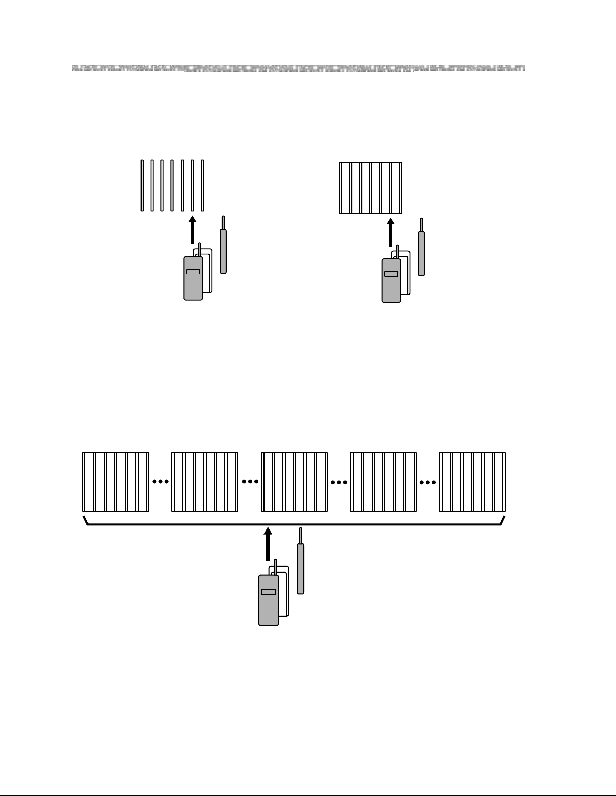
The following illustrations show which phone models and carriers can be used together:
Single Carrier Installation
If you have a Model 117A1 Carrier... If you have a Model 117A3 Carrier, or
Model 117A4 Carrier...
Note:
117A1, 117A1A, and
117A2 Carriers should
be replaced with 117A3
or 117A4 Carriers.
(No charge to
Use only...
MDW 9000 phones
(Code 7815H)
You can use...
MDW 9000 phones
(Code 7815H)
MDW 9000 phones
(Code 7815H03A)
MDW 9010 phones
(Code 7815H04A)
MDW 9030P phones
(Code 7815H05A)
MDW 9031 phones
(Code 7815H06A)
MDW 9031DCP phones
(Code 7815H08A)
MDW 9031 Dual Zone
(Code 781507A)
MDW 9031DCP Dual Zone
(Code 781509A)
Note: You can use Code 7815H phones together with other
phones only in a Model 117A3 or Model 117A4 single
carrier installation.
the customer).
®
9000 Products
Multiple (5 Max) Carrier Installation
If you have multiple Model 117A3 or Model 117A4 System Expansion Carriers (or both)...
Use only...
MDW 9010 phones
(Code 7815H04A)
MDW 9030P phones
(Code 7815H05A)
MDW 9031 phones
(Code 7815H06A)
MDW 9031DCP phones
(Code 7815H08A)
MDW 9031 Dual Zone
(Code 781507A)
Note: Multiple carrier installations must use MDW 9010 phones, MDW 9030P phones, and/or MDW
9031/9031DCP phones. MDW 9000 phones cannot be used in multiple carrier installations.
Note:
Fourth and fifth
carriers can be
used only with
PBX extensions.
MDW 9031/9031DCP Wireless Pocket Phone Installation and Use
503-801-1662 Issue 3 October 1999
Page 11

About the MDW 9031/9031DCP Pocket Phone Introduction 1
About the MDW 9031/9031DCP Pocket Phone
The MDW 9031/9031DCP Pocket Phone is not only wireless, but it is also lightweight and pocket-sized. A
removable carrying clip and a lanyard are provided with the handset. You can use either the clip or the lanyard
for hands-free portability. The MDW 9031/9031DCP also has a headset connector to accommodate an optional
headset.
You can be notified of an incoming call by either an alerter (which rings) or a vibrator, or both. There is a five-
line, user-activated backlit display that shows information you would see on a wired system phone’s display
(with the exception of the time), icons representing various handset functions (such as the alerter and the
vibrator), and the status of up to 12 telephone lines. The MDW 9031/9031DCP provides Redial, Hold, Mute,
Transfer, and Conference buttons, and allows you to program additional features on unused line buttons.
Privacy Informa tion
The MDW 9031/9031DCP Pocket Phone is designed to protect the privacy and security of your voice
conversation. The phone uses continuously changing radio frequencies and digital encoding techniques to make
it impossible for eavesdropping to occur through the use of commercially available analog radio scanners.
Where Can You Use Your Pocket Phone?
The MDW 9031/9031DCP Pocket Phone can be used in most typical office buildings, warehouses, malls, and
even outdoor areas such as loading do cks. The location of the radio mod ule gr eatly affects the performance of the
MDW 9031/9031DCP. Read the “Positioning a Radio Module or Carrier(s)” s e ction in Chapter 2 to determine
the best place to install the radio module. Repeat the tests several times with the radio module positioned in a
different location each time. To perform the tests, all you need is an electrical outlet for the radio module and a
charged battery pack in the handset.
MDW 9031/9031DCP Wireless Pocket Phone Installation and Use
503-801-166 Issue 3 October 1999 3
Page 12
1 Introduction About the MDW 9031/9031DCP Pocket Phone
)
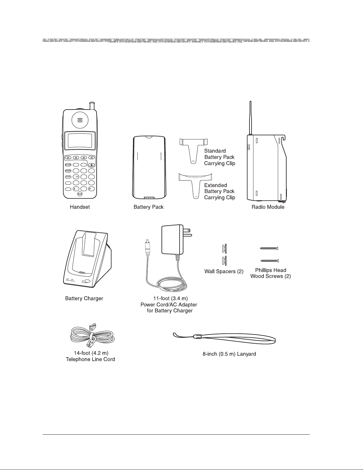
Parts List
Along with this book and the MDW 9031/9031DCP Pocket Phone Quick Reference, the box should contain the
items shown below. If it does not, call for customer support as described in the Copyright and Legal Notices at
the beginning of this book.
212 555 1212
MSG
ON
65
78
23 4
1
AB
Redial
On/Off
Feat/P
12
Conf
4
PQRS
Trans
Hold
Handset
CD
Standard
Battery Pack
Mute
ABC
DEF
3
GHI
JKL
MNO
5
6
WXYZ
TUV
97
8
OPER
0
Carrying Clip
Extended
Battery Pack
Carrying Clip
Battery Pack
POWER
RADIO
PASS
Radio Module
SPARE
HANDSET
REFRESH
Battery Charger
14-foot (4.2 m)
Telephone Line Cord
Wall Spacers (2)
Phillips Head
Wood Screws (2
11-foot (3.4 m)
Power Cord/AC Adapter
for Battery Charger
8-inch (0.5 m) Lanyard
MDW 9031/9031DCP Wireless Pocket Phone Installation and Use
503-801-1664 Issue 3 October 1999
Page 13
About the MDW 9031/9031DCP Pocket Phone Introduction 1
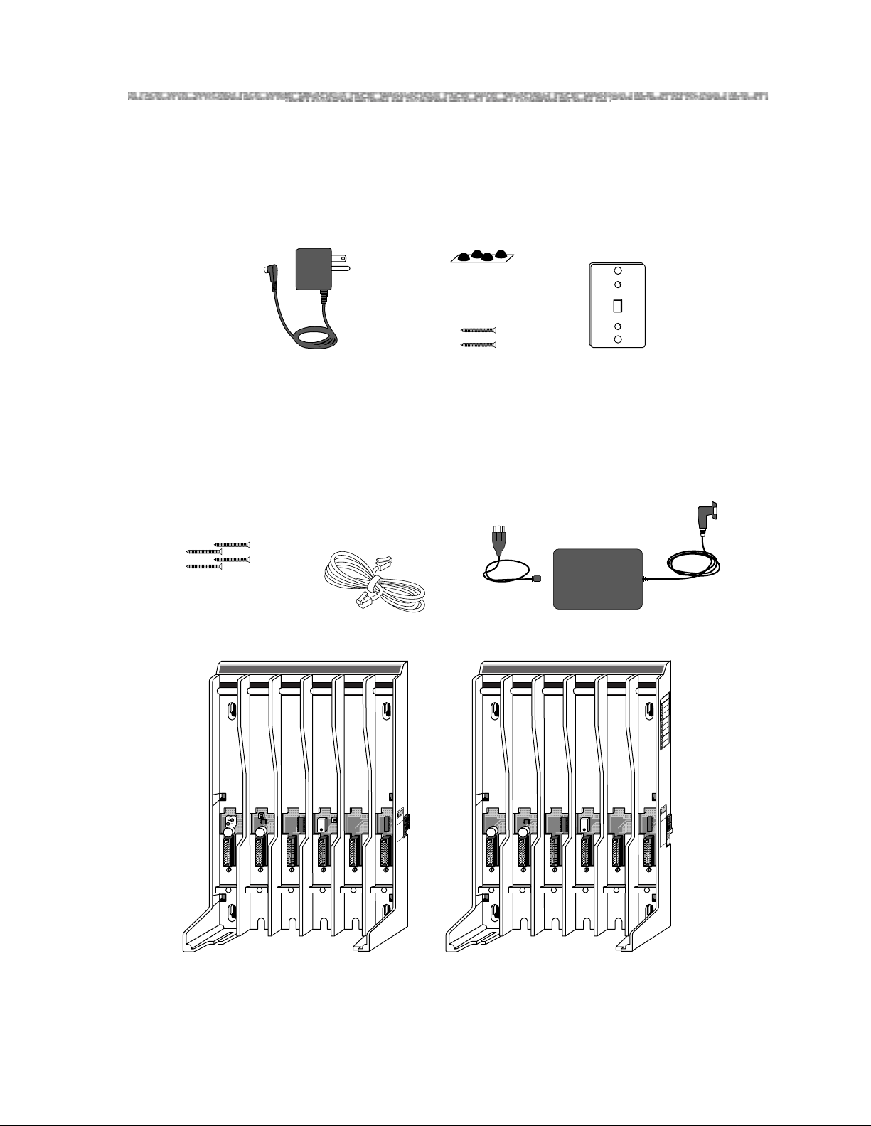
Additional Parts
The following parts may be necessary, depending upon your installation.
This Kit of Parts is required only when a single (stand-alone) MDW 9031/9031DCP Pocket Phone is
installed:
Rubber Feet (4)
Radio Module 11-foot (3.4 m)
Power Cord/AC Adapter
Philips Head
Wood Screws (2)
Wall Mounting
Plate
These additional parts are required when two or more MDW 9031/90 31DCP Poc ket Phones are instal led in
the same zone:
Philips Head
Wood Screws (4)
Expansion Cable 6-foot (1.8 m)
for multiple-carrier installation
T
RANSTALK
Carrier Assembly 25-foot (7.6 m)
Power Cord and Standard AC Adapter
T
RANSTALK
N
A
H
TR
P
A
E
O
R
N
G
N
R
M
TE
P
A
H
K
-O
ITE
C
A
R
P
E
R
U
R
M
TFA
R
E
LO
X
N
IE
R
LA
K
M
U
S
IP
M
E
R
LO
K
-O
ITE
C
A
R
P
E
R
U
R
M
TFA
R
E
LO
X
N
IE
R
LA
K
M
U
S
IP
M
E
R
LO
K
-O
ITE
C
A
R
P
E
R
K
-O
ITE
C
A
R
P
E
R
or
N
IO
T
U
21
O N
1 2 3 4
117A3 Carrier
N
IO
T
U
A
C
Y
L
N
O
E
E
S
L
21
O N
5
U
B
A
C
6
T
9
&
8
T
7
A
6
6
7
4
8
N
P
N
I
T
U
O
C
N
Y
S
F
O
T
U
O
6
1 2 3 4
5
117A4 Carrier
A
C
Y
L
N
O
E
E
S
L
U
B
A
C
6
T
9
&
8
T
7
A
6
6
7
4
8
N
P
N
I
T
U
O
C
N
Y
S
F
O
/
T
L
U
O
O
R
T
N
O
N
C
O
I
S
N
A
P
X
E
6
For information about ordering parts, see "Ordering Replacement and Optional Parts" in Chapter 4.
MDW 9031/9031DCP Wireless Pocket Phone Installation and Use
503-801-166 Issue 3 October 1999 5
Page 14
1 Introduction About the MDW 9031/9031DCP Pocket Phone
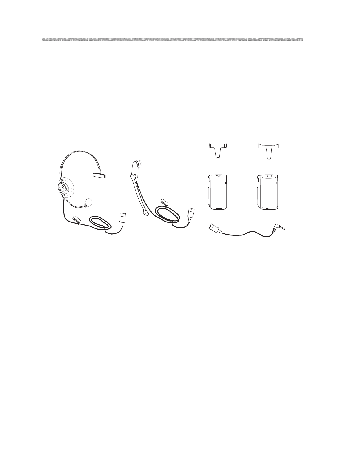
Spare Battery and Headset
One nickel metal hydride battery pack, which provides up to 3 hours of talk time, comes with your MDW
9031/9031DCP Pocket Phone. For ex tended pho ne usage, yo u should p urchase an add itional battery pack. If you
require full business-day use, you can purchase an extended battery pack. Although thicker and heavier than the
standard battery pack, the extended battery pack provides 8-9 hours of talk time when fully charged. You can
store the extra battery pack in the spare battery compartment of the battery charger. Then, when the battery pack
in the handset is low, you can switch battery packs.
®
T o help you answ er calls, an op tional Supra
a quick-disconnect adapter cord, which you can insert into the connector on the bottom of the handset to allow
hands-free conversation. For instructions for connecting the headset, see “Using a Headset” in Chapter 3.
9031 headset or a Radium (over - the-ear) head set can b e attached to
Standard Battery
Pack Clip
Standard
Battery Pack
Supra 9031 Headset Radium Headset
Adapter
For ordering information, see "Ordering Replacement and Optional Parts" in Chapter 4.
Extended Battery
Pack Clip
Extended
Battery Pack
MDW 9031/9031DCP Wireless Pocket Phone Installation and Use
503-801-1666 Issue 3 October 1999
Page 15

2 Installing the MDW 9031/9031DCP
Important Safety Instructions
This book contains instructions related to safety labels on the product:
!
WARNING:
WARNING indicates the presence of a hazard that can cause severe or
fatal personal injury if the hazard is not avoided.
!
CAUTION:
CAUTION indicates the presence of a hazard that will or can cause minor
personal injury or property damage if not avoided.
This phone is designed to provide trouble-free performance without any special
maintenance procedures. To reduce the risk of accidental damage:
• Keep the phone in an area free of dust, smoke, and moisture; do not block the air
vents by placing object s on top of the radio module.
• Do not place the phone or battery charger near a heating duct, radiator, or other
heat source, and do not drop or expose it to excessive shock or vibration.
Pocket Phone
• Unplug the battery charger, radio module, or carrier if its p ower cord is damaged,
if liquid is spilled into it, or if its housing becomes cracked or otherwise damaged.
• To clean your phone, wipe the outside housing with a soft, dust-free cloth. If
absolutely necessary, you may use a cloth slightly dampened with a mild soapand-water solution. Dry quickly with a soft cloth.
!
CAUTION:
Your phone contains sensitive electronic parts. Never submerge it in any kind
of liquid, and never use liquid or aerosol cleaners, detergents, alcohols,
solvents, abrasive cleaners, or an excessive amount of water when cleaning
the housing and faceplate. To do so could result in irreparable damage.
Guidelines for Safe and Efficient Operation
Your wireless telephone is a radio transmitter and receiver. When the phone is turned on, it receives and sends
out radio frequency (RF) energy. The phone operates in the frequency range of 902-928 MHz. Your hand-held
wireless telephone uses the digital TDD mode. The power is transmitted in bursts at a 200 Hz pulsed repetitio n
rate. The peak envelope transmit power is 325 mW or less.
Exposure to Radio Frequency Energy
The design of your wireless telephone complies with the latest Institute of Electrical
and Electronic Engineers (IEEE) and the American National Standards Institute
(ANSI) safety levels with respect to human exposure to RF energy. Of course, if you
would like to limit RF exposure even further, you may choose to control the duration
of your calls.
MDW 9031/9031DCP Wireless Pocket Phone Installation and Use
503-801-166 Issue 3 October 1999 7
Page 16

2 Installing the MDW 9031/9031DCP Pocket Phone Important Safety Instructions
!
CAUTION:
Cardiac Pacemakers
The MDW 9031/9031DCP handset is a radio device and, like all radio
devices, should not be placed next to a pacemaker.
Preliminary studies performed at the US Food and Drug Administration (FDA) and
elsewhere have shown that when digital cellular telephones are placed very close to
implanted cardiac pacemakers, interference with the operation of the implanted
pacemaker can occur. These preliminary studies show that interference does no t occur
when there is a reasonable distance between the telephone and the implanted
pacemaker and stops when the phone is turned off or moved so that it is more than 6
inches (15 cm) from the pacemaker. Digital cellular telephones operate at 0.6W.
TransTalk wireless telephones operate at a lower peak power of 325 mW or less
(100 mW, on an average).
Until more is known, the FDA suggests that people with pacemakers may want to
take some simple precautions when using or carrying digital wireless telephones.
They should ensure that there is ample distance between the digital wireless telephone
and the pacemaker—by not placing the phone next to the pacemaker implant (for
example, in a shirt or a coat pocket directly over the pacemaker implant) when the
phone is on and ready to receive a call and by hold ing it to the ear oppos ite the side of
the body where the pacemaker is implanted when using the phone. They should
consult their physicians or medical device manufacturers to determine if additional
precautions are necessary.
Hearing Aid Compatibility
Most electronic equipment, such as equipment in hospitals, is shielded from RF
energy. RF energy from wireless telephones, however, may affect some electronic
equipment.
Although the TransTalk wireless telephone is compatible with inductively coupled
hearing aids, a physician or hearing aid manufacturer should be consulted to
determine if a hearing aid is adequately shielded from external RF energy. The
operation of inadequately shielded medical devices may be adversely affected when a
portable wireless telephone is operating in close proximity.
Basic Safety Precautions for Installation and Us e
Always follow these basic safety precautions when installing or using this product to reduce risk of injury from
fire or electric shock.
!
WARNING:
Installation of this equipment for In-Range Out of Building (IROB)
conditions requires the use of protectors. See the documentation that
came with your communications system for more information.
!
CAUTION:
This equipment is for installation on Lucent Technologies PARTNER,
PARTNER Plus, PARTNER II, PARTNER Advanced Communications
System, MERLIN, MERLIN Plus, MERLIN II, MERLIN LEGEND, System 25,
System 75, System 85, and DEFINITY Communications Systems only.
MDW 9031/9031DCP Wireless Pocket Phone Installation and Use
503-801-1668 Issue 3 October 1999
Page 17

Important Safety Instructions Installing the MDW 9031/9031DCP Pocket Phone 2
• Read and understand all instructions in this book before using this produc t.
• Observe all warnings and instructions marked on the product.
• Do not use the product near water or when you are wet. If the product comes in
contact with any liquids, unplug the power cord and telephone line cords
immediately. Do not plug the product back in until it has dried thoroughly.
• Never push objects of any kind into this product through housing slots, since the
objects may touch hazardous voltage points or short out parts that could result in a
risk of electric shock. Never spill liquid of any kind on the phone.
• If you suspect a gas leak, report it immediately, but use a phone away from the
area in question. The phone’s electrical contacts could generate a tiny spark.
While unlikely, it is possible that this spark could ignite a heavy concentration of
gas. This product is not approved for use in areas labeled by the Occupational
Safety and Health Administration (OSHA) as “explosive environments.” Only
“Explosive Atmosphere Telephones” may be used in such hazardous
environments.
• Unplug this product from wall outlets and telephone jacks before cleaning. Clean
exposed parts with a soft, damp cloth. Do not use liquid or aerosol cleaners.
• Unplug this product from the wall outlet, remove the telephone line cord from the
modular wall jack or communications system switch/control unit, and refer
servicing to qualified service personnel under the following conditions:
~ When the power cord or plug is damaged or frayed.
~ If the product does not operate normally by following the operating
instructions. Adjust only those controls that are covered by the operating
instructions, since improper adjustment of other controls may result in damage
and will often require extensive work by a qualified technician to restore the
product to normal oper ation.
~ If the product has been dropped and the housing has been damaged.
• This product should be serviced by a qualified service center when service or
repair work is required. Do not open the product; there are no user-serviceable
components inside.
• Always unplug the power cord/AC adapter for the carrier(s) from the wall outlet
when:
~ Removing a radio module.
~ Moving a radio module to a new slot in the carrier.
~ Installing a new radio module.
~ Connecting or disconnecting telephone line cords.
~ Adding a carrier.
• Use only the type of battery pack shipped with this product or sold as an optional
part. (See “Ordering Replacement and Optional Parts” in Chapter 4.)
MDW 9031/9031DCP Wireless Pocket Phone Installation and Use
503-801-166 Issue 3 October 1999 9
Page 18

2 Installing the MDW 9031/9031DCP Pocket Phone Important Safety Instructions
!
WARNING:
The rechargeable battery pack may contain elements that are harmful to
the environment (for example, nickel). Do not burn or puncture the
battery pack. As with other batteries of this type, burning or puncturing
could release toxic material which could cause injury. Do not dis pose of
the battery pack in household garbage. For information about recycling
or proper disposal, consult your local solid waste (garbage) collection
or disposal organization.
Additional Safety Instructions for Installation Personnel
• Install the product to meet all environmental and electrical requirements listed in
Appendix C.
• All wiring that connects to this equipment and becomes part of the building
wiring must be a minimum of CLASS 2 or UL (Underwriters Laboratories)
Listed Communications cable.
• Do not install telephone wiring during a lightning storm.
• Do not install telephone jacks in a wet location unless the jack is specifically
designed for wet locations. Never touch uninsulated telephone wires or terminals
unless the telephone line has been disconnected at the network interface.
• Use caution when installing or modifying telephone lines.
• Install this product securely on a stable surface. Damage may result if the product
falls.
• Never place this product near or over a radiator or heat register.
• Slots and openings in the housing and the back or bottom are provided for
ventilation. To protect the housing from overheating, these openings must not be
blocked or covered. Therefore, do not place the product on a bed, sofa, rug, or
other similar surface. Also, do not place this product in an enclosed area unless
proper ventilation is provided.
• Install this product in a protected location where no one can step on or trip over
power cords and telephone line cords. Do not place objects on the cords that may
cause damage or abrasion.
• Do not allow anything to rest on the power cord. Do not locate this product where
the cord will be abused by persons walking on it. Do not overload wall outlets,
since this increases the risk of fire or electric shock. Do not staple or otherwise
attach the power cord to building surfaces.
• Use only the power supply (Comcode 847713583) shipped with this product for
the battery charger.
• Use only the power supply (Comcode 847523404) shipped with this product for
the radio module.
• Use only the power supply (Comcode 847224227) shipped with the carrier.
• Use only the correct power source. If y ou are not sure of the power supply to your
location, consult your local power company.
MDW 9031/9031DCP Wireless Pocket Phone Installation and Use
503-801-16610 Issue 3 October 1999
Page 19
Important Safety Instructions Installing the MDW 9031/9031DCP Pocket Phone 2
• This product uses a 3-prong plug. Such plugs are designed for your safety. Do not
attempt to defeat this purpose. If your wall outlet will not accept the plug, the
outlet should be replaced by an electrician.
!
WARNING:
Failure to properly ground this product will result in a risk of electrical
shock, which can cause serious personal injury. This product re quires a
3-prong AC outlet for safe operation. You should have your outlet
checked by a qualified electrician (see “AC Outlet Check” below) before
connecting this equipment.
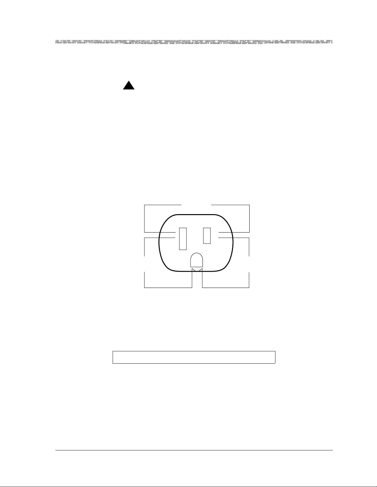
AC Outlet Check
Have a qualified electrician check all of the outlets into which the MDW 9031/9031DCP radio modules or
carriers, as well as the communications system switch/control unit, will be plugged. The electrician should check
that the hot, neutral, and ground wires are properly connected to the outlet by using a circuit tester.
The outlet can also be tested using a voltmeter to take the measurements as shown:
120 Volts
Neutral
Less than
1 volt
Phase
G
120
volts
If the outlet does not meet the electrical specifications for grounded outlets, your MDW 9031/9031DCP Pocket
Phone may not operate properly.
Note: If there is no current to the outlet or the voltages are not correct, the
problem should be corrected by a qualified electrician.
Go to “Installation Overview for Radio Modules and Carriers.”
MDW 9031/9031DCP Wireless Pocket Phone Installation and Use
503-801-166 Issue 3 October 1999 11
Page 20

2 Installing the MDW 9031/9031DCP Pocket Phone Installation Overview for Radio Modules
Installation Overview for Radio Modules and Carriers
This section explains how to install radio modules and carriers. You should proceed through this section in the
following order:
1 “Radio Module/Switch Wiring”
2 “Key Components”
3 “Posit ioning a Radio Module or Carrier(s )”
4 “Using Wireless Test Mode” (in Chapter 3)
5 Choose one of the following paths, depending upon which components you are
installing:
~ If you are installing a single radio module, go to “Installing a Single Radio
Module.”
~ If you are installing one or more carriers (from two to 24 radio modules), go
to “Understanding Carriers.”
Note: The illustrations in this chapter depict P ARTNER System hardware; your
hardware may differ from these illustrations.
Radio Module/Switch Wiring
If your installation requires customized wiring, the wiring technician should match the Pin numbers with the
switch interfaces as follows:
Switch Interface Pin #
ATL (MERLIN, DEFINITY) 1, 2
ETR (PARTNER) 3, 6
T/R (Tip/Ring) 5, 4
MDW 9031/9031DCP Wireless Pocket Phone Installation and Use
503-801-16612 Issue 3 October 1999
Page 21
Installation Overview for Radio Modules and Carriers Installing the MDW 9031/9031DCP Pocket
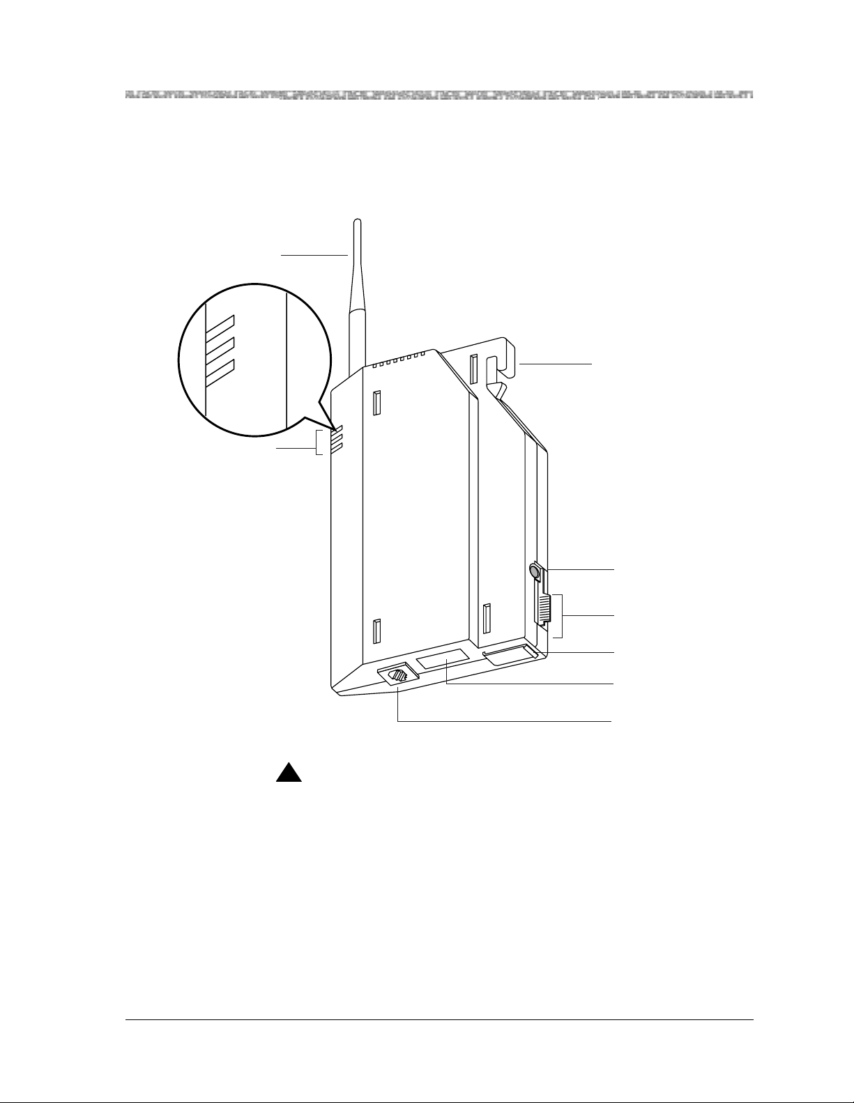
Key Components
Each radio module communicates with a corresponding handset. The matching sets are identified by a serial
number located on the bottom of the radio module and in the battery compartment of the handset.
Antenna
POWER
RADIO
PASS
LEDs
Radio
Module
O
P
RADIO
PASS
R
E
W
Mounting
Hook
Power Cord
Connector
Card Edge
(Cover not
shown)
Snap Lock
Serial Number
Telephone
Line Cord
Connector
!
CAUTION:
A carrier (Model 117A3 or Model 117A4) is required when installing two or
more MDW 9031/9031DCP Pocket Phones.
MDW 9031/9031DCP Wireless Pocket Phone Installation and Use
503-801-166 Issue 3 October 1999 13
Page 22
2 Installing the MDW 9031/9031DCP Pocket Phone Installation Overview for Radio Modules
To
Expansion
Carrier #1
CAUTION
U
S
E
O
N
L
Y
A
T
&
T
C
A
B
L
E
P
N
847667896
IN
OUT
OUT OF SYNC
CONTROL/
EXPANSION
From
Control Carrier
To
Expansion
Carrier #2
CAUTION
U
S
E
O
N
L
Y
A
T
&
T
C
A
B
L
E
P
N
847667896
IN
OUT
OUT OF SYNC
CONTROL/
EXPANSION
To
Expansion
Carrier #3
CAUTION
U
S
E
O
N
L
Y
A
T
&
T
C
A
B
L
E
P
N
847667896
IN
OUT
OUT OF SYNC
CONTROL/
EXPANSION
To
Expansion
Carrier #4
CAUTION
U
S
E
O
N
L
Y
A
T
&
T
C
A
B
L
E
P
N
8476678
96
IN
OUT
OUT OF SYNC
CONTROL/
EXPANSION
CAUTION
U
S
E
O
N
L
Y
A
T
&
T
C
A
B
L
E
P
N
84
7667
896
IN
OUT
OUT OF SYNC
CONTROL/
EXPANSION
T
Radio
Module
Mounting
Rods
RANSTALK
Wall Mount
Hole
Wall Mount
Hole
Label with
Model Number
(not shown)
Power Cord
Connector
(not shown)
Card Edge
Connectors
Slot
Numbers
Wall Mount
Hole
Cable
Manager Slot
1 2 3 4
CAUTION
Y
L
N
O
E
E
S
L
U
B
A
C
6
T
9
&
8
T
7
A
6
6
7
4
8
⁄N
P
IN
U
O
C
N
Y
S
F
O
T
L
U
O
O
R
T
N
N
O
C
IO
S
N
A
P
X
E
5
6
IN Jack
OUT Jack
OUT OF SYNC LED
T
/
CONTROL/EXPANSION LED
(Model 117A4 Only)
Wall Mount
Hole
Rear
Exit Slots
Using the expansion cable provided with each carrier, you can link up to five carriers.
From
Expansion
Carrier #1
From
Expansion
Carrier #2
From
Expansion
Carrier #3
21
O N
1 2 3 4
Control
Carrier
T
RANSTALK
N
A
H
R
T
P
A
E
O
R
N
G
N
R
E
M
T
P
A
H
K
O
-
E
T
I
C
A
R
P
E
R
U
R
M
A
F
T
R
O
E
L
X
N
E
I
R
A
L
K
M
U
S
P
I
M
E
R
O
L
K
O
-
E
T
I
C
A
R
P
E
R
U
R
M
A
F
T
R
O
E
L
X
N
E
I
R
A
L
K
M
U
S
P
I
M
E
R
O
L
K
O
-
E
T
I
C
A
R
P
E
R
K
O
-
E
T
I
C
A
R
P
E
R
N
O
I
T
U
A
C
Y
L
N
O
E
E
S
L
U
B
A
21
C
6
T
9
8
&
7
T
6
A
O N
6
7
4
8
N
P
N
I
T
U
O
C
N
Y
S
F
O
/
T
L
U
O
O
R
T
N
O
N
C
O
I
S
N
A
P
X
E
5 1 2 3 4
6
Expansion
Carrier #1
T
21
O N
21
O N
5 1 2 3 4
RANSTALK
N
A
H
R
T
P
A
E
O
R
N
G
N
R
E
M
T
P
A
H
K
O
-
E
T
I
C
A
R
P
E
R
U
R
M
A
F
T
R
O
E
L
X
N
E
I
R
A
L
K
M
U
S
P
I
M
E
R
O
L
K
O
-
E
T
I
C
A
R
P
E
R
U
R
M
A
F
T
R
O
E
L
X
N
E
I
R
A
L
K
M
U
S
P
I
M
E
R
O
L
K
O
-
E
T
I
C
A
R
P
E
R
K
O
-
E
T
I
C
A
R
P
E
R
N
O
I
T
U
A
C
Y
L
N
O
E
E
S
L
U
B
A
C
6
T
9
8
&
T
7
6
A
6
7
4
8
N
P
N
I
T
U
O
C
N
Y
S
F
O
/
T
L
U
O
O
R
T
N
O
N
C
O
I
S
N
A
P
X
E
6
Expansion
Carrier #2
T
RANSTALK
N
A
H
R
T
P
A
E
O
R
N
G
N
R
E
M
T
P
A
H
K
O
-
E
T
I
C
A
R
P
E
R
U
R
M
A
F
T
R
O
E
L
X
N
E
I
R
A
L
K
M
U
S
P
I
M
E
R
O
L
K
O
-
E
T
I
C
A
R
P
E
R
U
R
M
A
F
T
R
O
E
L
X
N
E
I
R
A
L
K
M
U
S
P
I
M
E
R
O
L
K
O
-
E
T
I
C
A
R
P
E
R
K
O
-
E
T
I
C
A
R
P
E
R
N
IO
T
U
A
21
O N
C
Y
L
N
O
E
E
S
L
U
B
A
21
C
6
T
9
8
&
T
7
6
A
O N
6
7
4
8
N
P
N
I
T
U
O
C
N
Y
S
F
O
/
T
L
U
O
O
R
T
N
O
N
C
O
I
S
N
A
P
X
E
5
1 2 3 4
6
Expansion
Carrier #3
T
RANSTALK
N
A
H
R
T
P
A
E
O
R
N
G
N
R
E
M
T
P
A
H
K
O
-
E
T
I
C
A
R
P
E
R
U
R
M
A
F
T
R
O
E
L
X
N
E
I
R
A
L
K
M
U
S
P
I
M
E
R
O
L
K
O
-
E
T
I
C
A
R
P
E
R
U
R
M
A
F
T
R
O
E
L
X
N
E
I
R
A
L
K
M
U
S
P
I
M
E
R
O
L
K
O
-
E
T
I
C
A
R
P
E
R
K
O
-
E
T
I
C
A
R
P
E
R
N
O
I
T
U
21
A
21
O N
C
O N
Y
L
N
O
E
E
S
L
U
B
A
21
C
6
T
9
8
&
T
7
6
A
O N
6
7
4
8
N
P
N
I
T
U
O
C
N
Y
S
F
O
/
T
L
U
O
O
R
T
N
O
N
C
O
I
S
N
A
P
X
E
5
1 2 3 4
6
Expansion
Carrier #4
(Fourth and fifth carriers can be
used only with PBX extensions.)
MDW 9031/9031DCP Wireless Pocket Phone Installation and Use
T
RANSTALK
N
A
H
R
T
P
A
E
O
R
N
G
N
R
E
M
T
P
A
H
K
O
-
E
T
I
C
A
R
P
E
R
U
R
M
A
F
T
R
O
E
L
X
N
E
I
R
A
L
K
M
U
S
P
I
M
E
R
O
L
K
O
-
E
T
I
C
A
R
P
E
R
U
R
M
A
F
T
R
O
E
L
X
N
E
I
R
A
L
K
M
U
S
P
I
M
E
R
O
L
K
O
-
E
T
I
C
A
R
P
E
R
K
O
-
E
T
I
C
A
R
P
E
R
N
O
I
T
U
A
C
Y
L
N
O
E
E
S
L
U
B
A
21
C
6
T
9
8
&
T
7
6
A
O N
6
7
4
8
N
P
N
I
T
U
O
C
N
Y
S
F
O
/
T
L
U
O
O
R
T
N
O
N
C
O
I
S
N
A
P
X
E
5
6
503-801-16614 Issue 3 October 1999
Page 23

Installation Overview for Radio Modules and Carriers Installing the MDW 9031/9031DCP Pocket
Positioning a Radio Module or Carrier(s)
Each of your handsets and its corresponding radio module operates within a single zone of coverage:
Approximately
500 to 900 feet in a
typical office building;
up to 1200 feet in
an unobstructed
environment
POWER
RADIO
PASS
Single Radio Module,
Single Carrier, or
Multiple Carriers
The range depends on your particular operating environment. For indoor use, walls between the handset and the
radio module will reduce the phone’s range. Avoid concentrations of structural metal, such as steel and
aluminum, and reinforced concrete.
Note: The MDW 9031/9031DCP Pocket Phone has a built-in testing feature
that you can use before final installation to help determine proper
placement of the radio module. To perform the tests, all you need is an
electrical outlet for the radio module and a charged battery pack in the
handset (you do not need a communications system switch/control unit).
The tests are described in “Using Wireless Test Mode” in Chapter 3.
General Positioning Rules
Failure to observe the following rules regarding location and use will result in
poor performance of your MDW 9031/9031DCP Pocket Phone.
• Position the radio module or carrier(s) in a central location, relative to the
handset(s) usage area, leaving at least 6 feet (1.8 m) between the radio module or
carrier(s) and the communications system switch/control unit or other wired
phones. If your switch/control unit is located in a remote location, you may have
to run a telephone line cord from your switch/control unit to the centrally
positioned radio module or carrier(s). The line cord maximum length is 1,000 feet
(305 m) of 26-gauge cable.
• Place the radio module or carrier(s) high on the wall for optimum voice quality
and range. Allow 6 to12 inches (15.2 to 30.5 cm) of space between the top of the
antenna on the radio module and the ceiling.
MDW 9031/9031DCP Wireless Pocket Phone Installation and Use
503-801-166 Issue 3 October 1999 15
Page 24

2 Installing the MDW 9031/9031DCP Pocket Phone Installation Overview for Radio Modules
• Never install the radio module or carrier(s) above a drop, suspended ceiling.
• Do not locate the radio module or carrier(s) within 3 feet (0.9 m) of any large
metal object, and be sure no metal objects are in the line of sight to the operating
area of the handset.
• Do not locate the radio module or carrier(s) within 6 feet (1.8 m) of
equipment with microprocessors, such as answering machines, personal
computers, and fax machines; control units, communications system
switches, or other phones (especially speakerphones); competing radio
devices such as wireless bar-code scanners; electromagnetic equipment such
as electric motors; or electrical main power feeds, junction boxes, circuitbreaker panels, fuse boxes, or 220-volt power lines.
• Be sure the radio module or carrier(s) does not share the same power line as
equipment with microprocessors such as answering machines, personal
computers, and fax machines or electromagnetic equipment such as electric
motors.
• If your communications system uses an uninterruptible power supply, such as a
backup generator, you may want to connect the radio module or carrier(s) to that
power supply.
Additional Rules for Installing a Single Radio Module Only
• Installing a single radio module on a shelf or desk is not recommended, because it
greatly reduces the range and quality of the transmission.
• Install a single radio module within 3 feet (0.9 m) of either side of, and within 6 to
8 feet (1.8 to 2.4 m) above, a properly grounded, 3-prong electrical outlet that is
not controlled by an on/off switch.
• You can install a single radio module in a remote location using a telephone line
cord to connect the radio module to the communications system switch/control
unit. IROBs must be used for out-of-building installations.
!
CAUTION:
A radio module cannot be installed outdoors.
MDW 9031/9031DCP Wireless Pocket Phone Installation and Use
503-801-16616 Issue 3 October 1999
Page 25
Installing a Single Radio Module Installing the MDW 9031/9031DCP Pocket Phone 2
Additional Rules for Installing One or More Carriers
• Install carrier(s) within 15 feet (5 m) of either side of, and within 6 to 8 feet (1.8
to 2.4 m) above, a properly grounded, 3-prong electrical outlet that is not
controlled by an on/off switch.
• Choose a location where handset users will not approach the carrier(s)
within a radius of 6 feet (1.8 m) for 1 or 2 carriers or 10 feet (3 m) for 3
carriers.
• When installing multiple carriers:
~ Install multiple carriers 1 foot (0.3 m) optimally to 4 feet (1.2 m) apart.
~ Install multiple carriers on the same horizontal axis (do not install one carrier
higher or lower than another).
~ Install the control carrier as the leftmost carrier, using only the expansion
cables provided.
~ Slot 6 of an 117A3 control carrier must always contain a radio module to pass
the synchronization signal to the next carrier.
!
CAUTION:
Carrier(s) cannot be installed outdoors.
Go to “Using Wireless Test Mode” in Chapter 3.
Installing a Single Radio Module
• Install a single radio module high on a wall, leaving 6 to 12 inches (15.2 to
30.5 cm) between the top of the antenna and the ceiling.
• See “Key Components” earlier in this chapter for additional picture detail.
To install a single radio module:
1 Perform the tests described in “Using Wireless Test Mode” in Chapter 3 to
determine the optimal placement of the radio module. To perform the tests, all
you need is an electrical outlet for the rad io m odu le and a charged battery pack in
the handset.
2 Check to be sure the radio module’s power cord is unplugged from the wall outlet
before continuing.
MDW 9031/9031DCP Wireless Pocket Phone Installation and Use
503-801-166 Issue 3 October 1999 17
Page 26
2 Installing the MDW 9031/9031DCP Pocket Phone Installing a Single Radio Module
3 Detach the rubber feet from the shipping card. Apply them to marked areas on the
underside of the radio module.
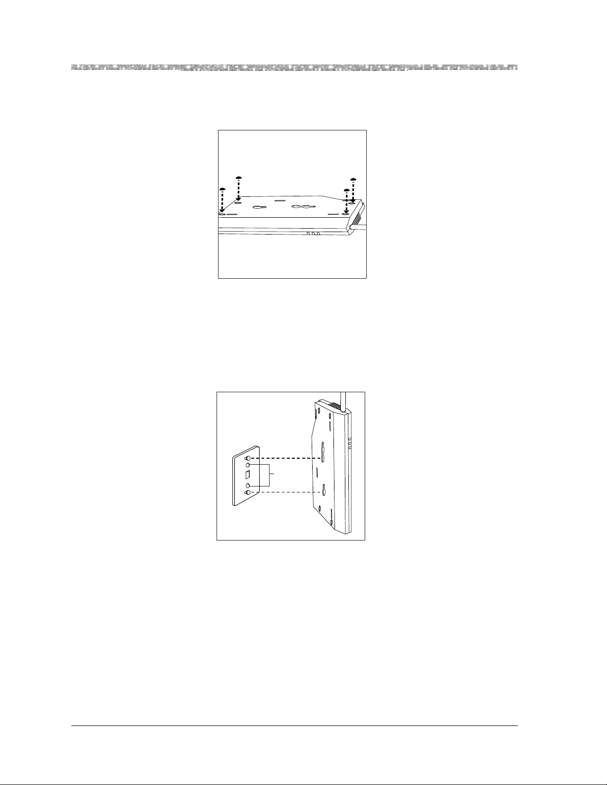
4 Place the wall-mounting plate against the wall. Choose a location backed by a
wooden stud (if unavailable, use toggle bolts instead of the supplied wood
screws). Lightly tap a nail into the wall to start holes. Then screw the plate flush
to the wall. Place the radio module over the plate, then slide it downward to lock
it into place.
Note: Do not remove the plastic cap covering the radio module’s card edge.
Screw
Holes
MDW 9031/9031DCP Wireless Pocket Phone Installation and Use
503-801-16618 Issue 3 October 1999
Page 27
Installing a Single Radio Module Installing the MDW 9031/9031DCP Pocket Phone 2
N
S
I
O
N
S
X
T
E
N
S
I
O
N
S
MUSIC
ON
HOLD
5 Insert one end of the telephone line cord into an extension jack or terminal/station
connector on your communications system switch/control unit (refer to your
communications system manual for the proper location).
PFT
L
I
N
PFT
E
L
S
I
N
PFT
E
L
PAGE
S
I
N
PFT
E
L
SMDR
S
I
N
PFT
E
L
S
I
N
206
MODULE
E
S
PFT
206
MODULE
PFT
PROCESSOR
E
MODULE
X
T
400
E
E
MODULE
X
N
T
S
400
VOL
E
MODULE
I
N
O
S
N
E
I
S
X
MUSIC
O
ON
T
N
HOLD
E
E
S
X
N
T
S
E
I
N
O
S
N
I
S
O
N
S
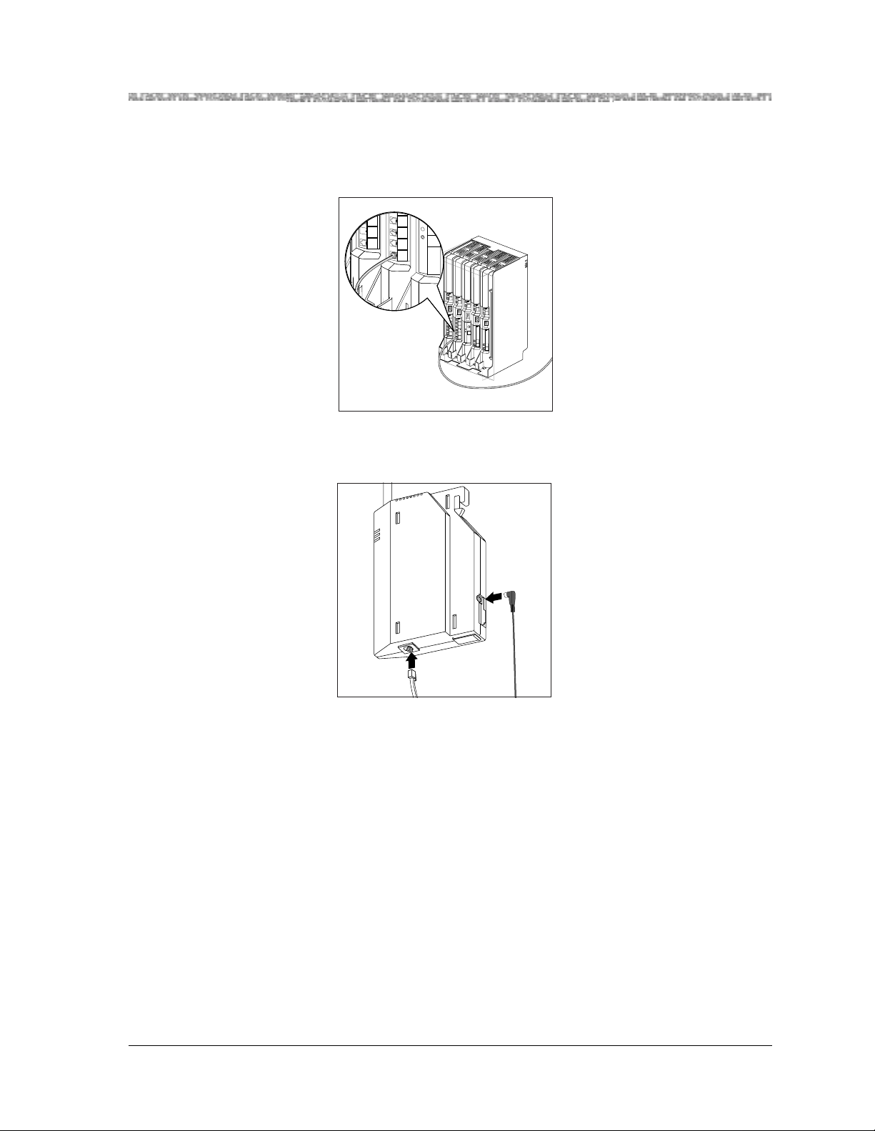
6 Insert the radio module’s power cord into the side of the radio module. Insert the
other end of the telephone line cord into the bottom of the radio module.
o
i
d
a
R
le
u
d
o
M
POWER
RADIO
PASS
MDW 9031/9031DCP Wireless Pocket Phone Installation and Use
503-801-166 Issue 3 October 1999 19
Page 28
2 Installing the MDW 9031/9031DCP Pocket Phone Installing a Single Radio Module
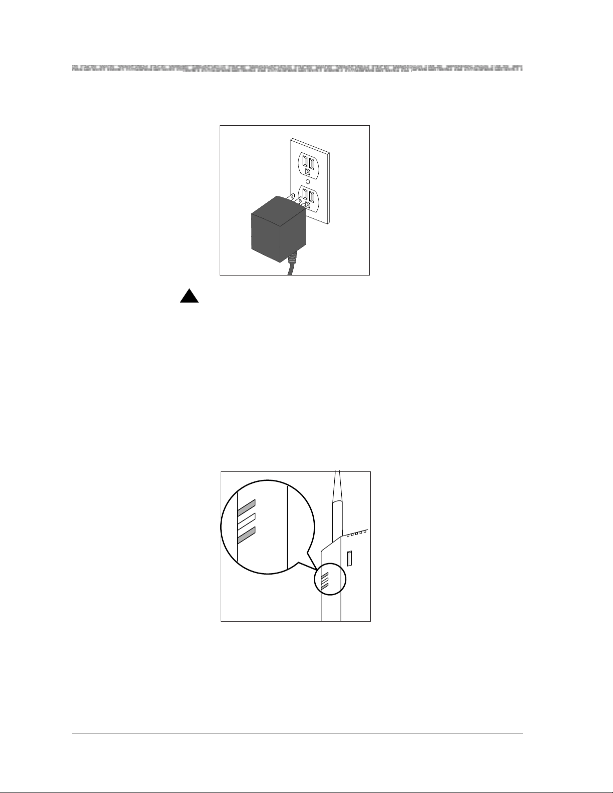
7 Plug the power cord/AC adapter into a properly grounded, 3-prong wall outlet
that is not controlled by an on/off switch.
!
CAUTION:
Never connect or disconnect the telephone line cord while the radio module is
plugged into the wall outlet.
Single Radio Module Installation Self-Test
Verify that the POWER and PASS LEDs on the radio module light. If the radio module’s PASS LED does not
light:
1 Unplug the power cord/AC adapter from the wall outlet.
2 Wait 15 seconds.
3 Plug it in again.
POWER
RADIO
PASS
Radio
R
Module
E
W
PO
IO
D
A
R
PASS
4 If the radio module’s PASS LED still d oes not light, refer to Chapter 5,
“Troubleshooting.”
MDW 9031/9031DCP Wireless Pocket Phone Installation and Use
503-801-16620 Issue 3 October 1999
Page 29

Understanding Carriers Installing the MDW 9031/9031DCP Pocket Phone 2
Note: The RADIO LED also may light upon installation; however, since the
RADIO LED has no significance during installation, ignore its operation.
The RADIO LED indicates a connection between the handset and the
radio module; it lights when the handset is being used as long as th e
battery pack in the handset is charged.
Understanding Carriers
When you install more than one radio module in a single zone, you must mount the r adio modules in a carrier, so
that their signals will be synchronized. A carrier can hold up to six radio modules. The MDW 9031/9031DCP
Pocket Phone is designed to work with either of two carrier models: Model 117A3, and Model 117A4.
Note: If you currently own a Model 117A1, 117A1A, or 117A2 carrier, Lucent
Technologies will replace it with a Model 117A3 or Model 117A4 at no
charge.
If you want to install more than six radio modules, you will need more than one carrier. Systems configured as
key systems (for example, PARTNER or MERLIN) can accommodate up to 18 radio modules (three carriers);
PBX systems can accommodate up to 24 radio modules (four carriers).
In any multiple-carrier installation, the leftmost carrier acts as the control carrier, and the remaining carriers act
as expansion carriers, passing along the synchronization signal from the control carrier. Multiple carrier
installations require that you use Model 117A3 or Model 117A4 carriers, or both.
The Model 117A3 and Model 117A4 carriers are similar in gener al appearance, b ut the installation pr ocedure for
the two models differs somewhat. A label on the left side of the carrier identifies the carrier model number.
If you are installing one model of carrier, go to either of the
following sections:
• If installing a Model 117A3 carrier, go to “Understanding
Your Model 117A3 Carrier.”
• If installing a Model 117A4 carrier, go to “Understanding
Your Model 117A4 Carrier.”
If you are installing both carrier models, read both of these
sections.
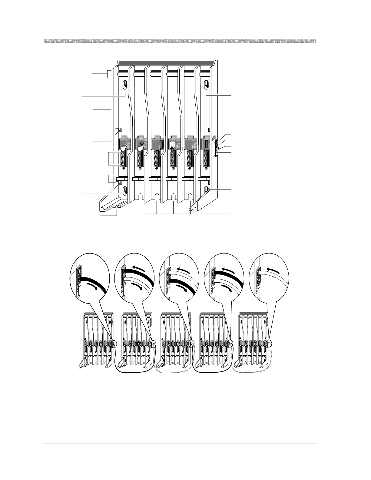
Understanding Your Model 117A3 Carrier
The installation of a Model 117A3 carrier differs in three ways from the installation of a Model 117A4 carrier:
• You may need to adjust the power DIP switch.
• You must set the Control/Expansion DIP switch.
• If you use the 117A3 as the control carrier, you must have a radio module
installed in Slot 6 of that carrier in order to pass the synchronization signal on to
the next carrier.
MDW 9031/9031DCP Wireless Pocket Phone Installation and Use
503-801-166 Issue 3 October 1999 21
Page 30
2 Installing the MDW 9031/9031DCP Pocket Phone Understanding Carriers
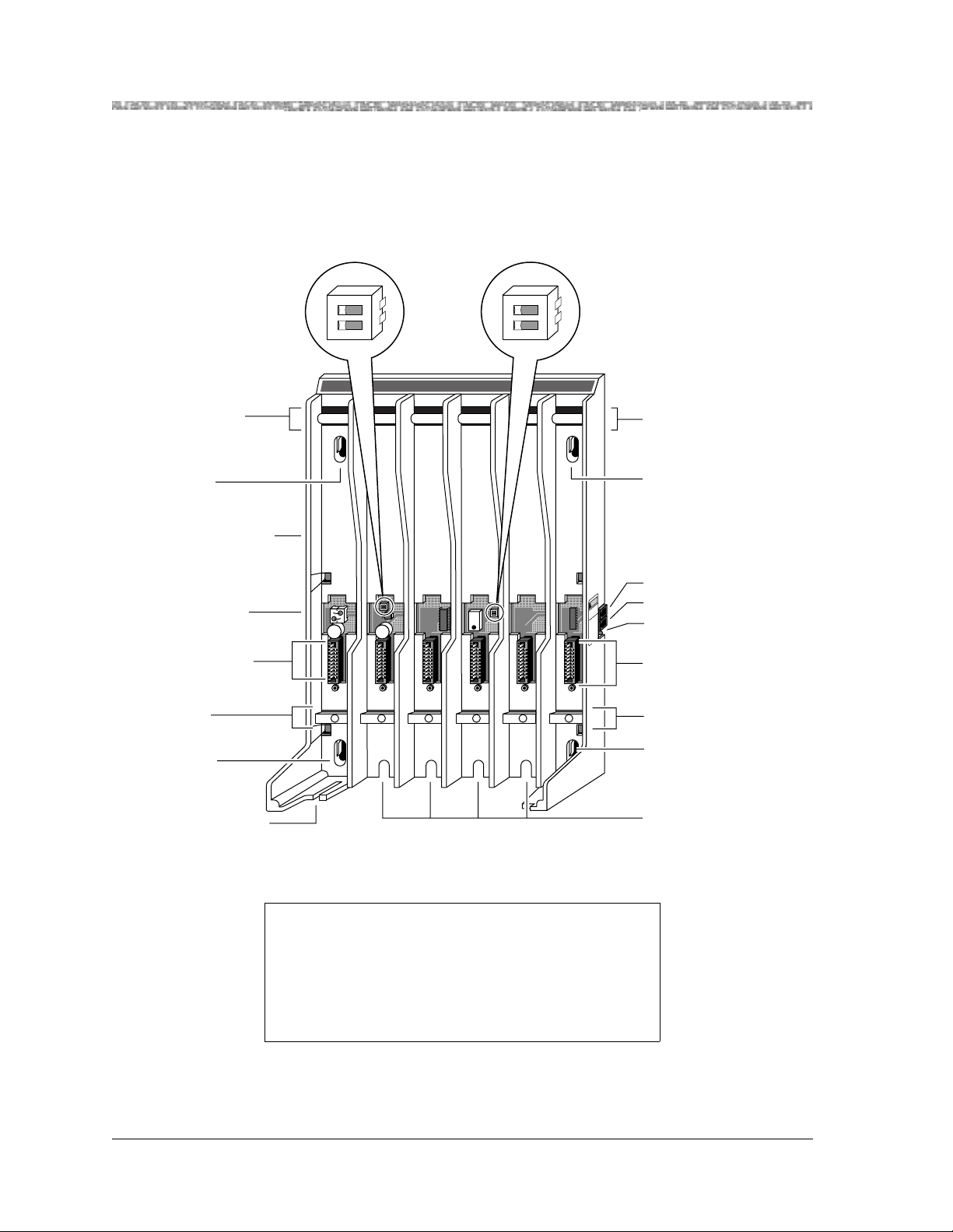
As the following illustration shows, each Model 117A3 carrier has two user-adjustable DIP switches—one in
Slot 2 that controls the power levels, and another in Slot 4 that specifies whether this particular carrier is
functioning as a control or an expansion carrier.
Radio
Module
Mounting
Rods
Wall Mount
Hole
Label with
Model Number
(not shown)
Power Cord
Connector
(not shown)
Card Edge
Connectors
Power DIP
Switch
21
O N
4
Control/Expansion
DIP Switch
21
O N
T
RANSTALK
Radio
Module
Mounting
Rods
Wall Mount
Hole
In Jack
21
O N
21
O N
CAUTION
Y
L
N
O
E
E
S
L
U
B
A
C
6
T
9
&
8
T
7
A
6
6
7
4
8
⁄N
P
IN
OUT
OUT OF SYNC
Out Jack
Out of Sync LED
Card Edge
Connectors
Slot
Numbers
Wall Mount
Hole
Cable
Manager Slot
1 2 3 4
5
6
Go to either of the following sections:
• If you need to adjust the 117A3 carrier’ s rang e to prevent
overlapping with other wireless products, go to
“Setting the 117A3 Carrier Power Level.”
• To skip that section, go to “Setting the 117A3 Carrier
Control/Expansion DIP Switch.”
MDW 9031/9031DCP Wireless Pocket Phone Installation and Use
Slot
Numbers
Wall Mount
Hole
Rear
Exit Slots
503-801-16622 Issue 3 October 1999
Page 31

Understanding Carriers Installing the MDW 9031/9031DCP Pocket Phone 2
Setting the 117A 3 Carrier Power Level
If your MDW 9031/9031DCP Pocket Phones are interfering with other wireless
products in use or if you anticipate that they will, you can adjust the carrier’s range by
setting each 117A3 carrier’s power DIP switch, located in Slot 2.
21
O N
O N
1
21
O N
Power
DIP Switch
1 2 3 4
Slot 2
The power DIP switch must be adjusted while the carrier is without power and while
Slot 2 is empty. You can adjust it before mounting the carrier on the wall.
5
MDW 9031/9031DCP Wireless Pocket Phone Installation and Use
503-801-166 Issue 3 October 1999 23
Page 32

2 Installing the MDW 9031/9031DCP Pocket Phone Understanding Carriers
Use a nonmetallic, pointed object to set each 117A3 carrier’s DIP switch according to
the following table.
Note: You must set the DIP switch for all of the 117A3 carriers to the same
setting.
Desired Range (approximate) Power DIP Switch Settings
(Maximum power setting)–500 to
900 feet (152 to 274 m)
O N
300 to 500 feet (91 to 152 m)
O NO N
150 to 300 feet (46 to 91 m)
100 to 150 feet (31 to 46 m)
O N
Go to “Setting the 117A3 Carrier Control/Expansion DIP Switch.”
MDW 9031/9031DCP Wireless Pocket Phone Installation and Use
503-801-16624 Issue 3 October 1999
Page 33

Understanding Carriers Installing the MDW 9031/9031DCP Pocket Phone 2
Setting the 117A 3 Carrier Control/Expansion DIP Switch
O N
Control/Expansion
DIP Switch
The Model 117A3 carrier can serve as either a control or an expansion carrier.
Whether you install one or more 11 7A3 carri ers , you must set the Contro l/E xpan sion
DIP switch in Slot 4 of each 117A3 carrier to indicate which role that carrier is filling.
21
O N
21
O N
1
1 2 3 4
Slot 4
The leftmost carrier, no matter what model number it is, must be the control carrier,
and the remaining carriers are expansion carriers. The control carrier acts as the
“lead” carrier—its transmit and receive patterns control the expansion carriers,
ensuring that all of the linked carriers function as a single system.
5
It is recommended that you determine which carrier is to be the control carrier and
which, if any, will be expansion carriers; then set the Control/Expansion DIP
switch(es) before mounting the carrier(s) on the wall.
MDW 9031/9031DCP Wireless Pocket Phone Installation and Use
503-801-166 Issue 3 October 1999 25
Page 34

2 Installing the MDW 9031/9031DCP Pocket Phone Understanding Carriers
Use a nonmetallic, pointed object to set each 117A3 carrier’s DIP switch according to
the following table.
Note: Only one carrier (the leftmost carrier) can be the control car rier; the ot her
carriers must be expansion carriers.
To designate the carrier as a... Use this setting for the DIP switch...
control carrier (one carrier only)
O N
expansion carrier (one or more
additional carriers)
O N
Go to one of the following:
• If you are installing a single 117A3 carrier, go to
“Installing a Single Carrier.”
• If you are installing multiple 117A3 carriers, go to
“Installing Multiple Carriers.”
• If you are also installing one or more 117A4 carriers, go to
“Understa nding Your Model 117A4 Carrier.”
MDW 9031/9031DCP Wireless Pocket Phone Installation and Use
503-801-16626 Issue 3 October 1999
Page 35

Understanding Carriers Installing the MDW 9031/9031DCP Pocket Phone 2
Understanding Your Model 117A4 Carrier
The Model 117A4 carrier differs from the 117A3 in that it does not require that Slot 6 contain a radio module in
order to pass the signal from the control carrier to the next carrier. It also does not have Power and
Control/Expansion DIP switches to set. The 117A4 automatically adjusts its power level and senses whether it is
being used as a control or an expansion carrier.
As the following illustration shows, the 117A4 does have an additional LED located on the right side of the
carrier, the CONTROL/EXPANSION LED; this is used to determine whether the cabling was installed
correctly.
T
Radio
Module
Mounting
Rods
Wall Mount
Hole
Label with
Model Number
(not shown)
RANSTALK
Radio
Module
N
A
H
R
T
P
A
E
O
R
N
G
N
R
E
M
T
P
A
H
K
O
-
E
IT
C
A
R
P
E
R
U
R
M
A
F
T
R
O
E
L
X
N
IE
R
A
L
K
M
U
S
IP
M
E
R
O
L
K
-O
E
IT
C
A
R
P
E
R
U
R
M
A
F
T
R
O
E
L
X
N
IE
R
A
L
K
M
U
S
IP
M
E
R
O
L
K
O
-
E
IT
C
A
R
P
E
R
K
O
-
E
IT
C
A
R
P
E
R
Mounting
Rods
SYNC and CONTROL/EXP
LED Codes Label
Wall Mount
Hole
Power Cord
Connector
(not shown)
Card Edge
Connectors
Slot
Numbers
Wall Mount
Hole
Cable
Manager Slot
1 2 3 4
N
IO
T
U
A
C
Y
L
N
O
E
E
S
L
U
B
A
C
6
T
9
&
8
T
7
6
A
6
7
4
8
⁄N
P
IN
T
U
O
C
YN
F S
T O
L/
U
O
NTRO
N
CO
SIO
PAN
EX
5
6
IN Jack
OUT Jack
CONTROL/EXPANSION LED
(Model 117A4 Only)
Slot
Numbers
Wall Mount
Hole
Rear
Exit Slots
MDW 9031/9031DCP Wireless Pocket Phone Installation and Use
503-801-166 Issue 3 October 1999 27
Page 36

2 Installing the MDW 9031/9031DCP Pocket Phone Understanding Carriers
The following chart explains the label that identifies the jacks and LEDs on the 117A4 carrier. (The IN and OUT
jacks and the OUT OF SYNC LED also appear on the 117A3 carrier.)
Label Explanation
IN Designates the modular jack that accepts the
modular plug and cable from the preceding
carrier to the left. If the jack is in use, this
carrier is an “expansion” carrier.
OUT Designates the modular jack that accepts a
modular plug and cable to connect this
carrier to the next carrier to the right. This
carrier can be either a “control” carrier (if it
is the leftmost carrier) or an “expansion”
carrier.
OUT OF SYNC Designates the upper of two LEDs. If the
LED is not lit, the carrier is “in sync.”
If the LED glows red, the carrier is out of
synchronization. Call Customer Supp ort as
described in the Copyright and Legal
Notices at the beginning of this book.
CONTROL/EXPANSION Designates the lower of two LEDs. The
color of the LED indicates the carrier
configuration:
Control carrier = green LED
Expansion carrier = amber LED
The light pattern indicates whether the
carrier is operational:
Glowing steadily = no problem
Blinking = no radio module(s) in the carrier
MDW 9031/9031DCP Wireless Pocket Phone Installation and Use
503-801-16628 Issue 3 October 1999
Page 37

Understanding Carriers Installing the MDW 9031/9031DCP Pocket Phone 2
The label at the top of the right side of the carrier is provided to help you interpret the LED lights. The first three
lines on this label refer to LEDs on the control carrier, the next three lines refer to the LEDs on each of the
expansion carriers, and the last two lines apply to all carriers.
Go to either of the following:
• If installing a single carrier, go to “Installing a Single Carrier.”
• If installing multiple carriers, go to “Installing Multiple
Carriers.”
MDW 9031/9031DCP Wireless Pocket Phone Installation and Use
503-801-166 Issue 3 October 1999 29
Page 38

2 Installing the MDW 9031/9031DCP Pocket Phone Installing a Single Carrier
Installing a Single Carrier
If you are installing a Model 117A3 carrier, be sure you have read the following sections and have set the DIP
switches:
• “Understanding Your Model 117A3 Carrier”
• “Setting the 117A3 Carrier Power Level”
• “Setting the 117A3 Carrier Control/Expansion DIP Switch”
Then go to either of the following:
• “Installing a Single Carrier on a Shelf or Desk”
• “Installing a Single Carrier on a Wall”
If you are installing a Model 1 17A4 ca rrier , b e su re you hav e read “Unders tandin g Your Model 117A4 Carrier .”
Then go to either of the following:
• “Installing a Single Carrier on a Shelf or Desk”
• “Installing a Single Carrier on a Wall”
MDW 9031/9031DCP Wireless Pocket Phone Installation and Use
503-801-16630 Issue 3 October 1999
Page 39

Installing a Single Carrier Installing the MDW 9031/9031DCP Pocket Phone 2
Installing a Single Carrier on a Shelf or Desk
• You will not receive optimum performance if the unit is placed on a desk or low
shelf.
• Install the unit as high as possible, leaving 6 to 12 inches (15.2 to 30.5 cm)
between the top of the antenna and the ceiling, if on a high shelf.
• Never install or remove a radio module from a carrier that is plugged into a wall
outlet (hot insertion).
• See “Key Components” earlier in this chapter for additional picture detail.
To install a single carrier:
1 Perform the tests described in “Using Wireless Test Mode” in Chapter 3 to
determine the optimal placement of the radio module. To perform the tests, all
you need is an electrical outlet for the rad io m odu le and a charged battery pack in
the handset.
2 Check to be sure the carrier’s power cord is unplugg ed from the wall outlet before
continuing.
3 Remove the plastic cap covering each radio module’s card edge before installing
the radio modules in the carrier.
MDW 9031/9031DCP Wireless Pocket Phone Installation and Use
503-801-166 Issue 3 October 1999 31
Page 40

2 Installing the MDW 9031/9031DCP Pocket Phone Installing a Single Carrier
4 Starting from the leftmost slot (#1), insert each radio module into the carrier by
hooking it onto the radio module mounting rod. Slowly swing the radio module’s
card edge into the card edge connector on the back of the carrier.
5 When the card edge is fully seated, a snap lock on the bottom of the radio module
will engage.
MDW 9031/9031DCP Wireless Pocket Phone Installation and Use
503-801-16632 Issue 3 October 1999
Page 41

Installing a Single Carrier Installing the MDW 9031/9031DCP Pocket Phone 2
6 Insert a telephone line cord into the bottom of each radio module.
7 Slide the telephone line cords through the rear exit slots on the bottom of the
carrier. Cords originating from Modules 1 and 6 can share exit slots with cords
from Modules 2 and 5, respectively.
MDW 9031/9031DCP Wireless Pocket Phone Installation and Use
503-801-166 Issue 3 October 1999 33
Page 42

2 Installing the MDW 9031/9031DCP Pocket Phone Installing a Single Carrier
MUSIC
ON
HOLD
N
S
I
O
N
S
X
T
E
N
S
I
O
N
S
8 Insert the free end of the telephone line cord into the appropriate extens ion jack or
terminal/station connector on your communications system switch/control unit
(refer to your communications system manual for the proper location).
PFT
L
I
N
PFT
E
L
S
I
N
PFT
E
L
PAGE
S
I
N
PFT
E
L
SMDR
S
I
N
PFT
E
L
S
I
N
206
MODULE
E
S
PFT
206
MODULE
PFT
PROCESSOR
E
MODULE
X
T
400
E
E
MODULE
X
N
T
S
400
VOL
E
MODULE
I
N
O
S
N
E
I
S
X
MUSIC
O
ON
T
N
HOLD
E
E
S
X
N
T
S
E
I
N
O
S
N
I
S
O
N
S
9 Insert the carrier’s AC adapter cord into the left side of the carrier.
1 2345
MDW 9031/9031DCP Wireless Pocket Phone Installation and Use
503-801-16634 Issue 3 October 1999
Page 43

Installing a Single Carrier Installing the MDW 9031/9031DCP Pocket Phone 2
10 Place the carrier on its feet towards the back of the shelf or desk, making sure it is
in a stable position. Be sure the telephone line cords come out the rear exit slots in
the back of the unit. Arrange the power cor d and telep hon e line co rds b eneath the
shelf or desk, so no one can step on them or trip over them.
11 Insert the carrier’s power cord into the AC adapter, then plug the power cord into
a properly grounded, 3-prong wall outlet that is not controlled by an on/off
switch.
If appropriate, you can wall-mount the AC adapter using its attached wallmounting bracket.
!
CAUTION:
Never connect or disconnect telephone line cords, or insert or remove radio
modules, while the carrier is plugged into the wall outlet.
12 Go to “Single Carrier Installation Self-Test” (page 40).
MDW 9031/9031DCP Wireless Pocket Phone Installation and Use
503-801-166 Issue 3 October 1999 35
Page 44

2 Installing the MDW 9031/9031DCP Pocket Phone Installing a Single Carrier
Installing a Single Carrier on a Wall
• Install the unit high on a wall, leaving 6 to 12 inches (15.2 to 30.5 cm) between
the top of the antenna and the ceiling.
• Never install or remove a radio module from a carrier that is plugged into a wall
outlet (hot insertion).
• See “Key Components” earlier in this chapter for additional picture detail.
To wall-mount a single carrier:
1 Perform the tests described in “Using Wireless Test Mode” in Chapter 3 to
determine the optimal placement of the radio module. To perform the tests, all
you need is an electrical outlet for the rad io m odu le and a charged battery pack in
the handset.
2 Check to be sure the carrier’s power cord is unplugg ed from the wall outlet before
continuing.
3 Place the carrier against the wall. Choose a location backed by a wooden stud (if
unavailable, use toggle bolts instead of the supplied wood screws). Hold the
carrier straight; use a level if needed. Using a nail or pencil, mark screw locations
through the four wall-mount holes.
Start the screws, leaving the screw heads protruding approximately ½ inch
(12 mm) from the wall. Place the carrier assembly over the screws, then slide it
downward to lock it into place. Tighten the screws.
T
RANSTALK
N
A
H
R
T
P
A
E
O
R
N
G
N
R
E
M
T
P
A
H
K
O
-
E
T
I
C
A
R
P
E
R
U
R
M
A
F
T
R
O
E
L
X
N
E
I
R
A
L
K
M
U
S
P
I
M
E
R
O
L
K
O
-
E
T
I
C
A
R
P
E
R
U
R
M
A
F
T
R
O
E
L
X
N
E
I
R
A
L
K
M
U
S
P
I
M
E
R
O
L
K
O
-
E
T
I
C
A
R
P
E
R
K
O
-
E
T
I
C
A
R
P
E
R
N
O
I
T
U
A
C
Y
L
N
O
E
E
S
L
U
B
A
C
6
T
9
&
8
T
7
A
6
6
7
4
8
N
⁄
P
IN
T
U
O
C
N
Y
S
F
O
/
T
L
U
O
O
R
T
N
N
O
C
IO
S
N
A
P
X
E
1 2 3 4
5
6
MDW 9031/9031DCP Wireless Pocket Phone Installation and Use
503-801-16636 Issue 3 October 1999
Page 45

Installing a Single Carrier Installing the MDW 9031/9031DCP Pocket Phone 2
4 Remove the plastic cap covering each radio module’s card edge before inserting
the radio modules into the carrier.
5 Starting from the leftmost slot (#1), insert each radio module into the carrier by
hooking it onto the radio module mounting rod. Slowly swing the radio m odu le’s
card edge into the card edge connector on the back of the carrier.
6 When the card edge is fully seated, a snap lock on the bottom of the radio module
will engage.
MDW 9031/9031DCP Wireless Pocket Phone Installation and Use
503-801-166 Issue 3 October 1999 37
Page 46

2 Installing the MDW 9031/9031DCP Pocket Phone Installing a Single Carrier
MUSIC
ON
HOLD
N
S
I
O
N
S
X
T
E
N
S
I
O
N
S
7 Insert a telephone line cord into the bottom of each radio module.
8 Slide the telephone line cords through the cable manager slot on the left front of
the carrier.
9 Insert the free end of each telephone line cord into the appropriate extension jack
or terminal/station connector on your communications system switch/control unit
(refer to your communications system manual for the proper location).
PFT
L
I
N
PFT
E
L
S
I
N
PFT
E
L
PAGE
S
I
N
PFT
E
L
SMDR
S
I
N
PFT
E
L
S
I
N
206
MODULE
E
S
PFT
206
MODULE
PFT
PROCESSOR
E
MODULE
X
T
400
E
E
MODULE
X
N
T
S
400
VOL
E
MODULE
I
N
O
S
N
E
I
S
X
MUSIC
O
ON
T
N
HOLD
E
E
S
X
N
T
S
E
I
N
O
S
N
I
S
O
N
S
MDW 9031/9031DCP Wireless Pocket Phone Installation and Use
503-801-16638 Issue 3 October 1999
Page 47
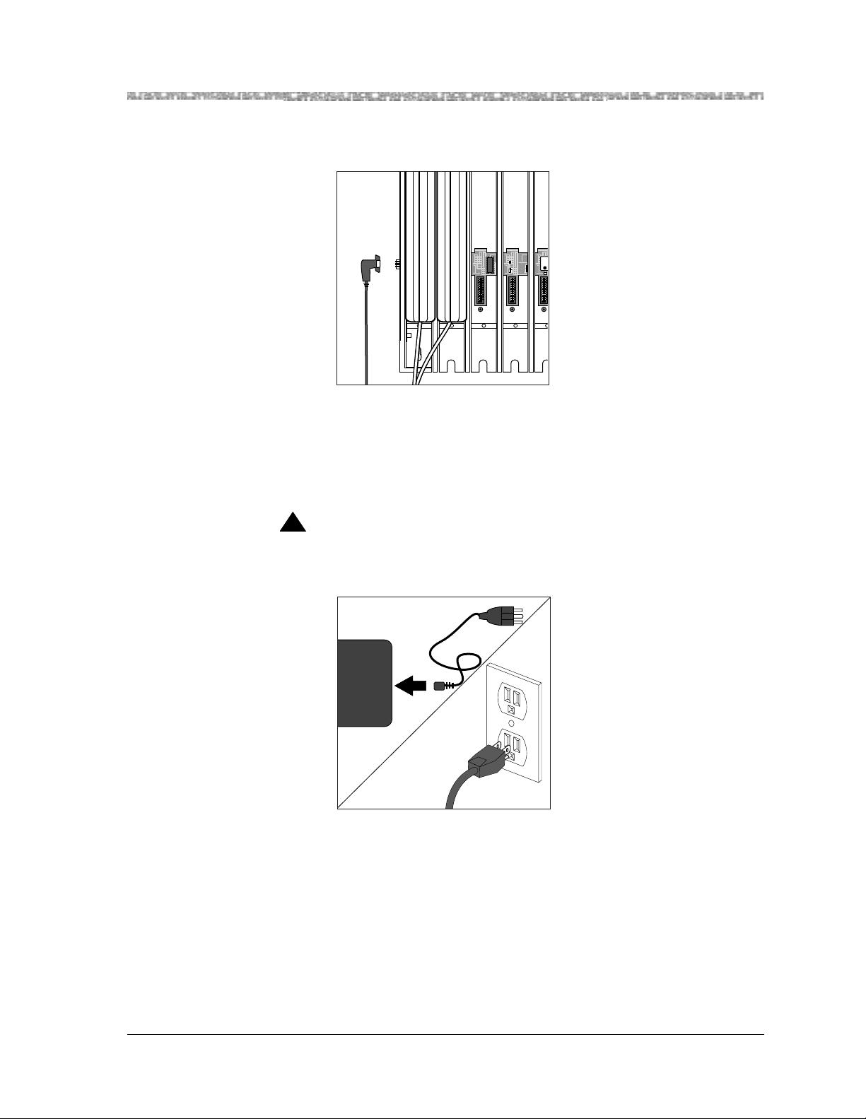
Installing a Single Carrier Installing the MDW 9031/9031DCP Pocket Phone 2
10 Plug the carrier’s AC adapter cord into the left side of the carrier.
1 2345
11 Insert the carrier’s power cord into the AC adapter, then plug the power cord into
a properly grounded, 3-prong wall outlet that is not controlled by an on/off
switch.
If appropriate, you can wall-mount the AC adapter using its attached wallmounting bracket.
!
CAUTION:
Never connect or disconnect telephone line cords, or insert or remove radio
modules, while the carrier is plugged into the wall outlet.
12 Go to “Single Carrier Installation Self-Test” (page 40).
MDW 9031/9031DCP Wireless Pocket Phone Installation and Use
503-801-166 Issue 3 October 1999 39
Page 48

2 Installing the MDW 9031/9031DCP Pocket Phone Installing a Single Carrier
Single Carrier Installation Self-Test
To perform a single carrier self-test:
1 A single carrier must always function as a control carrier. Wait a few seconds,
then check the LED(s) on the right side of the carrier:
~ Model 117A4:
Compare the OUT OF SYNC and CONTROL/EXPANSION LEDs against
the top three lines on the “SYNC and CONTROL/EXP LED Codes” label.
~ Model 117A3:
The 117A3 has no CONTROL/EXPANSION LED. The OUT OF SYNC
LED should not be lit.
2 If the OUT OF SYNC LED is lit, power down, wait at least 15 seconds, and then
repower the carrier. If the LED is still lit, follow the suggestions in the
“Installation Problems” section of Chapter 5, “Troubleshooting.” If the LED is
still lit, call Customer Support as described in the Copyright and Legal Notices at
the beginning of this book.
OUT OF S YNC
CONTROL/
T
4
1 2 3 4
RANSTALK
21
O N
21
O N
5
EXPANSION
N
A
H
R
T
P
A
E
O
N
N
R
M
G
R
E
T
P
A
H
K
O
-
E
T
I
C
A
R
P
E
R
U
R
M
A
F
T
R
E
X
O
L
N
E
I
R
A
L
K
M
U
S
P
I
M
E
R
O
L
K
O
-
E
T
I
C
A
R
P
E
R
U
R
M
A
F
T
R
E
X
O
L
N
E
I
R
A
L
K
M
U
S
P
I
M
E
R
O
L
K
O
-
E
T
I
C
A
R
P
E
R
K
O
-
E
T
I
C
A
R
P
E
R
N
O
I
T
U
A
C
Y
L
N
O
E
E
S
L
U
B
A
C
6
T
9
&
8
T
7
6
A
6
7
4
8
⁄N
P
N
I
T
U
O
C
N
Y
S
F
O
T
U
O
6
MDW 9031/9031DCP Wireless Pocket Phone Installation and Use
503-801-16640 Issue 3 October 1999
Page 49

Installing Multiple Carriers Installing the MDW 9031/9031DCP Pocket Phone 2
3 If you are using a Model 117A4 carrier, verify that the carrier’s
CONTROL/EXPANSION LED is lit and that its color is green. This is correct
for a single-carrier installation.
4 Verify that the POWER and PASS LEDs on each radio module are lit. If a radio
module’s PASS LED does not light, power down the carrier and the module, wait
15 seconds, and repower the module and then the carrier. If the PASS LED still
does not light, refer to Chapter 5, “Troubleshooting.”
POWER
RADIO
PASS
Radio
R
Module
E
W
O
P
IO
D
A
R
PASS
Note: The RADIO LED also may light upon installation; however, since the
RADIO LED has no significance during installation, ignore its operation.
The RADIO LED indicates a connection between the handset and the
radio module; it lights when the handset is being used as long as th e
battery pack in the handset is charged.
Installing Multiple Carriers
• Install each carrier high on a wall, leaving 6 to 12 inches (15.2 to 30.5 cm)
between the top of the antennas and the ceiling.
• Install each carrier 1 foot (0.3 m) optimally to 4 feet (1. 2 m) f rom its neigh bor in g
carrier.
• Never install or remove a radio module from a carrier that is plugged into a wall
outlet (hot insertion).
• See “Key Components” earlier in this chapter for additional picture detail.
Go to “Handset.”
MDW 9031/9031DCP Wireless Pocket Phone Installation and Use
503-801-166 Issue 3 October 1999 41
Page 50

2 Installing the MDW 9031/9031DCP Pocket Phone Installing Multiple Carriers
Multiple-carrier installation involves several stages:
• Mounting the carriers on the wall and cabling them.
• Installing a single radio module in each carrier.
• Installing the remaining radio modules.
The most efficient method for installing carriers and their radio modules is to perform self-tests after each stage
of the installation. This enables you to spot any problems at an early stage and to avoid the necessity for
deinstalling the components in order to solve problems.
Mounting and Cabling Multiple Carriers
Perform the tests described in “W ireless Test Mode” in Chapter 3 to determine the optimal placement o f the radio
module. To perform the tests, all you need is an electrical outlet for the radio module and a charged battery pack
in the handset.
If you are installing 117A3 carriers and need to adjust the power setting to avoid interference from other wireless
products, see “Setting the 117A3 Carrier Power Lev el.” Also make sure yo u have set the Control/Ex pansion DI P
switch correctly (see “Setting the 117A3 Carrier Control/Expansion DIP Switch”).
To mount and connect cable for multiple carriers:
1 Check to be sure the carrier’s power cord is unplugg ed from the wall outlet before
continuing.
2 Choose a location backed by a wooden stud for the carrier (if unavailable, use
toggle bolts instead of the supplied wood screws).
T
RANSTALK
N
A
H
R
T
P
A
E
O
R
N
G
N
R
E
M
T
P
A
H
K
O
-
E
T
I
C
A
R
P
E
R
U
R
M
A
F
T
R
O
E
L
X
N
E
I
R
A
L
K
M
U
S
P
I
M
E
R
O
L
K
O
-
E
T
I
C
A
R
P
E
R
U
R
M
A
F
T
R
O
E
L
X
N
E
I
R
A
L
K
M
U
S
P
I
M
E
R
O
L
K
O
-
E
T
I
C
A
R
P
E
R
K
O
-
E
T
I
C
A
R
P
E
R
N
O
I
T
U
A
C
Y
L
N
O
E
E
S
L
U
B
A
C
6
T
9
&
8
T
7
6
A
6
7
4
8
N
⁄
P
N
I
T
U
O
C
N
Y
S
F
O
/
T
L
U
O
O
R
T
N
N
O
C
O
I
S
N
A
P
X
E
1 2 3 4
5
6
Note: The leftmost carrier must be the control carrier; all of the others are
expansion carriers.
Place the carrier against the wall, leaving enough room to the right for additional
carrier(s) if applicable. Hold the carrier straight; use a level if needed. Using a
nail or pencil, mark screw locations through the four wall-mount holes. Start the
screws, leaving the screw heads protruding approximately ½ inch (12 mm) from
the wall.
3 Repeat Steps 1 through 3 for each carrier, leaving 1 foot (0.3 m) optimally to 4
feet (1.2 m) between carriers.
MDW 9031/9031DCP Wireless Pocket Phone Installation and Use
503-801-16642 Issue 3 October 1999
Page 51

Installing Multiple Carriers Installing the MDW 9031/9031DCP Pocket Phone 2
4 Place the carrier assembly over the screws, then slide it downward to lock it into
place. Be sure that the leftmost carrier is the control carrier. Tighten the screws.
Repeat for each carrier.
5 Connect an expansion cable to the OUT jack of the control carrier.
CAUTION
LY
N
O
E
E
S
L
U
B
A
C
6
9
8
7
6
AT&T
6
7
4
8
N
⁄
P
IN
OUT
YNC
OUT OF S
CONTROL/
EXPANSION
6 Insert the free end of the expansion cable into the IN jack of the expansion carrier
immediately to the right of the control carrier.
Note: Although installing an expansion cable into the wrong IN or OUT jack
will not harm either carrier, doing so causes all handsets to work
improperly and the OUT OF SYNC LED to light.
CAUTION
USE ONL Y
AT&T CABLE
P⁄N 847667896
IN
T
U
O
OUT OF SYNC
CONTROL/
EXPANSION
From
Control
Carrier
7 If you have a second expansion carrier:
a Connect an expansion cable to the OUT jack of expansion carrier #1.
b Insert the free end of the expansion cable into the IN jack of expansion
carrier #2.
See “Key Components” earlier in this chapter for an illustration of a fourcarrier setup.
MDW 9031/9031DCP Wireless Pocket Phone Installation and Use
503-801-166 Issue 3 October 1999 43
Page 52

2 Installing the MDW 9031/9031DCP Pocket Phone Installing Multiple Carriers
8 Plug an AC adapter cord into the left side of each carrier.
1 2345
9 Insert each carrier’s power cord into its AC adapter.
If appropriate, you can wall-mount each AC adapter using its attached wallmounting bracket.
MDW 9031/9031DCP Wireless Pocket Phone Installation and Use
503-801-16644 Issue 3 October 1999
Page 53

Installing Multiple Carriers Installing the MDW 9031/9031DCP Pocket Phone 2
10 Plug each carrier’s power cord into one of the following power sour ces that is not
controlled by an on/off switch:
~ Surge-suppressor strip.
~ Properly grounded, 3-prong wall outlets. (See “wall outlets” in the following
chart for the order in which to power up the carriers.)
11 Power the carriers as follows:
If the carriers are plugged
into...
Then...
one surge suppressor strip Power the strip.
Result:
All the carriers will turn on simultaneously.
wall outlets Plug in the power for the carriers in this order:
T
!
CAUTION:
21
O N
1 2 3 4
Control
Carrier
1
RANSTALK
N
A
H
R
T
P
A
E
O
N
N
R
M
G
R
E
T
P
A
H
K
O
-
E
T
I
C
A
R
P
E
R
U
R
M
A
F
T
R
E
X
O
L
N
E
I
R
A
L
K
M
U
S
P
I
M
E
R
O
L
K
O
-
E
T
I
C
A
R
P
E
R
U
R
M
A
F
T
R
E
X
O
L
N
E
I
R
A
L
K
M
U
S
P
I
M
E
R
O
L
K
O
-
E
T
I
C
A
R
P
E
R
K
O
-
E
T
I
C
A
R
P
E
R
N
O
I
T
U
A
C
Y
L
N
O
E
E
S
L
U
21
B
A
C
6
T
9
&
8
O N
T
7
A
6
6
7
4
8
⁄N
P
N
I
T
U
O
C
N
Y
S
F
O
T
U
O
5
1 2 3 4
6
Expansion
Carrier #1
T
RANSTALK
N
A
H
R
T
P
A
E
O
N
N
R
M
G
R
E
T
P
A
H
K
O
E
T
I
C
A
R
P
E
R
U
R
M
A
F
T
R
E
X
O
L
N
E
I
R
A
L
K
M
U
S
P
I
M
E
R
O
L
K
O
E
T
I
C
A
R
P
E
R
U
R
M
A
F
T
R
E
X
O
L
N
E
I
R
A
L
K
M
U
S
P
I
M
E
R
O
L
K
O
E
T
I
C
A
R
P
E
R
K
O
E
T
I
C
A
R
P
E
R
N
O
I
T
U
21
O N
A
C
Y
L
N
O
E
E
S
L
U
21
B
A
C
6
T
9
&
8
O N
T
7
A
6
6
7
4
8
⁄N
P
N
I
T
U
O
C
N
Y
S
F
O
T
U
O
5
1 2 3 4
6
Expansion
Carrier #2
2 3
T
RANSTALK
N
A
H
R
T
P
A
E
O
N
N
R
M
G
R
E
T
P
A
H
K
O
-
E
T
I
C
A
R
P
E
R
U
R
M
A
F
T
R
E
X
O
L
N
E
I
R
A
L
K
M
U
S
P
I
M
E
R
O
L
K
O
-
E
T
I
C
A
R
P
E
R
U
R
M
A
F
T
R
E
X
O
L
N
E
I
R
A
L
K
M
U
S
P
I
M
E
R
O
L
K
O
-
E
T
I
C
A
R
P
E
R
K
O
-
E
T
I
C
A
R
P
E
R
N
O
I
T
U
21
O N
A
21
C
O N
Y
L
N
O
E
E
S
L
U
21
B
A
C
6
T
9
&
8
O N
T
7
A
6
6
7
4
8
⁄N
P
N
I
T
U
O
C
N
Y
S
F
O
T
U
O
5
1 2 3 4
6
Expansion
Carrier #3
4
Never connect or disconnect expansion cables or telephone line cords, or
insert or remove radio modules, while the carrier is plugged into the wall
outlet.
T
RANSTALK
N
A
H
R
T
P
A
E
O
N
N
R
M
G
R
E
T
P
A
H
K
O
-
E
T
I
C
A
R
P
E
R
U
R
M
A
F
T
R
E
X
O
L
N
E
I
R
A
L
K
M
U
S
P
I
M
E
R
O
L
K
O
-
E
T
I
C
A
R
P
E
R
U
R
M
A
F
T
R
E
X
O
L
N
E
I
R
A
L
K
M
U
S
P
I
M
E
R
O
L
K
O
-
E
T
I
C
A
R
P
E
R
K
O
-
E
T
I
C
A
R
P
E
R
N
O
I
T
U
A
C
Y
L
N
O
E
E
S
L
U
21
B
A
C
6
T
9
&
8
O N
T
7
A
6
6
7
4
8
⁄N
P
N
I
T
U
O
C
N
Y
S
F
O
T
U
O
5
6
1 2 3 4
T
RANSTALK
N
A
H
R
T
P
A
E
O
N
N
R
M
G
R
E
T
P
A
H
K
O
-
E
T
I
C
A
R
P
E
R
U
R
M
A
F
T
R
E
X
O
L
N
E
I
R
A
L
K
M
U
S
P
I
M
E
R
O
L
K
O
-
E
T
I
C
A
R
P
E
R
U
R
M
A
F
T
R
E
X
O
L
N
E
I
R
A
L
K
M
U
S
P
I
M
E
R
O
L
K
O
-
E
T
I
C
A
R
P
E
R
K
O
-
E
T
I
C
A
R
P
E
R
N
O
I
T
U
21
O N
A
C
Y
L
N
O
E
E
S
L
U
21
B
A
C
6
T
9
&
8
O N
T
7
A
6
6
7
4
8
N
⁄
P
N
I
T
U
O
C
N
Y
S
F
O
T
U
O
5
6
Expansion
Carrier #4
5
12 Go to “Multiple Carrier Mounting and Cabling Self-Test” (page 46).
MDW 9031/9031DCP Wireless Pocket Phone Installation and Use
503-801-166 Issue 3 October 1999 45
Page 54
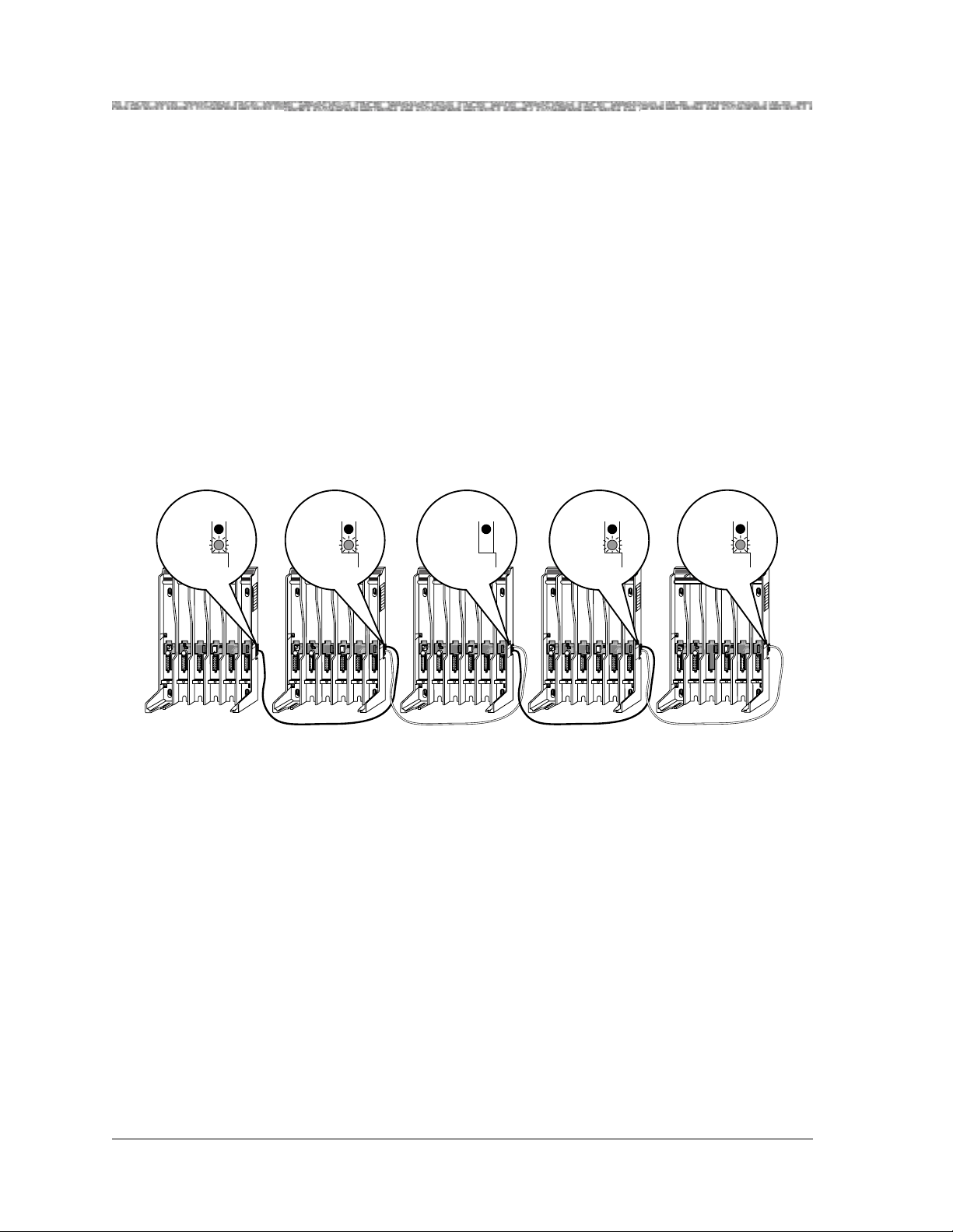
2 Installing the MDW 9031/9031DCP Pocket Phone Installing Multiple Carriers
Multiple Carrier Mounting and Cabling Self-Test
To perform a multiple carrier mounting and cabling self-test:
1 Wait a few seconds after powering up the carriers, then verify that the red OUT
OF SYNC LEDs on all carriers are lit. This is normal when no radio modules
have yet been installed. The CONTROL/EXPANSION LEDs (Mod el 117A4
only) should also be lit and blinking:
~ Model 117A4 control carrier = green blinking
~ Model 117A4 expansion carrier(s) = green blinking
A Model 117A3 carri er has no CONTROL/EXPANSION LED, but the DIP
switch in Slot 4 of the carrier must be set correctly to either Control or Expansion.
2 The following illustration shows the correct LED status for a five-carrier
installation with no radio modules installed. This sample installation has four
117A4 carriers—one acting as the control carrier and the other three acting as
expansion carriers—and one 117A3 carrier acting as an expansion carrier.
OUT OF SYNC (red)
CONTROL/
EXPANSION
4
1 2 3 4
(green) CONTROL/
21
O N
21
O N
5 1 2 3 4
Control
Carrier
Model
117A4
N
A
H
R
T
P
A
E
O
R
N
G
N
R
E
M
T
P
A
H
K
O
-
E
T
I
C
A
R
P
E
R
U
R
M
A
F
T
R
O
E
L
X
N
E
I
R
A
L
K
M
U
S
P
I
M
E
R
O
L
K
O
-
E
T
I
C
A
R
P
E
R
U
R
M
A
F
T
R
O
E
L
X
N
E
I
R
A
L
K
M
U
S
P
I
M
E
R
O
L
K
O
-
E
T
I
C
A
R
P
E
R
K
O
-
E
T
I
C
A
R
P
E
R
N
O
I
T
U
A
C
Y
L
N
O
E
E
S
L
B
A
C
6
T
9
&
8
7
6
6
7
4
8
N
I
T
U
O
C
N
Y
S
F
O
/
L
T
U
O
R
T
N
N
O
C
O
I
S
N
A
P
X
E
OUT OF SYNC (red)
(DIP switch
in Slot 4 set to
Expansion)
4
21
O N
21
O N
5
Expansion
Carrier #2
Model
117A3
OUT OF SYNC (red)
RANSTALK
6
4
CAUTION
Y
L
N
O
E
E
S
L
U
B
A
C
6
T
9
&
8
T
7
A
6
6
7
4
8
N
⁄
P
N
I
T
U
O
C
N
Y
S
F
O
T
U
O
21
O N
1 2 3 4
T
EXPANSION
(green)
T
RANSTALK
21
A
O N
P
O
5
6
Expansion
Carrier #3
Model
117A4
OUT OF SYNC (red)
RANSTALK
6
4
N
A
H
R
T
P
A
E
O
R
N
G
N
R
E
M
T
P
A
H
K
O
-
E
T
I
C
A
R
P
E
R
U
R
M
A
F
T
R
O
E
L
X
N
E
I
R
A
L
K
M
U
S
P
I
M
E
R
O
L
K
O
-
E
T
I
C
A
R
P
E
R
U
R
M
A
F
T
R
O
E
L
X
N
E
I
R
A
L
K
M
U
S
P
I
M
E
R
O
L
K
O
-
E
T
I
C
A
R
P
E
R
K
O
-
E
T
I
C
A
R
P
E
R
N
O
I
T
U
A
C
Y
L
N
O
E
E
S
L
U
B
A
C
6
T
9
&
8
T
7
6
A
6
7
4
8
N
⁄
P
N
I
T
U
O
C
N
Y
S
F
O
/
L
T
U
O
R
O
T
N
N
O
C
O
I
S
N
A
P
X
E
O N
T
EXPANSION
(green) CONTROL/
T
RANSTALK
21
U
21
T
A
O N
N
⁄
P
O
5 1 2 3 4
6
Expansion
Carrier #1
Model
117A4
N
A
H
R
T
P
A
E
O
R
N
G
N
R
E
M
T
P
A
H
K
O
-
E
T
I
C
A
R
P
E
R
U
R
M
A
F
T
R
O
E
L
X
N
E
I
R
A
L
K
M
U
S
P
I
M
E
R
O
L
K
O
-
E
T
I
C
A
R
P
E
R
U
R
M
A
F
T
R
O
E
L
X
N
E
I
R
A
L
K
M
U
S
P
I
M
E
R
O
L
K
O
-
E
T
I
C
A
R
P
E
R
K
O
-
E
T
I
C
A
R
P
E
R
N
O
I
T
U
A
C
Y
L
N
O
E
E
S
L
U
B
A
C
6
T
9
&
8
T
7
6
6
7
4
8
N
⁄
N
I
T
U
O
C
N
Y
S
F
O
/
L
T
U
O
R
T
N
N
O
C
O
I
S
N
A
P
X
E
OUT OF SYNC (red)
CONTROL/
EXPANSION
4
21
O N
21
O N
1 2 3
4
5
Expansion
Carrier #4
Model
117A4
(green)
T
RANSTALK
N
A
H
R
T
P
A
E
O
R
N
G
N
R
E
M
T
P
A
H
K
O
-
E
T
I
C
A
R
P
E
R
U
R
M
A
F
T
R
O
E
L
X
N
E
I
R
A
L
K
M
U
S
P
I
M
E
R
O
L
K
O
-
E
T
I
C
A
R
P
E
R
U
R
M
A
F
T
R
O
E
L
X
N
E
I
R
A
L
K
M
U
S
P
I
M
E
R
O
L
K
O
-
E
T
I
C
A
R
P
E
R
K
O
-
E
T
I
C
A
R
P
E
R
N
O
I
T
U
A
C
Y
L
N
O
E
E
S
L
U
B
A
C
6
T
9
&
8
T
7
6
A
6
7
4
8
N
⁄
P
N
I
T
U
O
C
N
Y
S
F
O
/
L
T
U
O
R
O
T
N
N
O
C
O
I
S
N
A
P
X
E
6
MDW 9031/9031DCP Wireless Pocket Phone Installation and Use
503-801-16646 Issue 3 October 1999
Page 55

Installing Multiple Carriers Installing the MDW 9031/9031DCP Pocket Phone 2
3 At this stage of your installation, verify the LEDs displayed match the third of the
SYNC and CONTROL/EXP LED Codes label, depending on whether the carrier
is the control or an expansion carrier.
4 If the LEDs on your installation do not reflect this pattern, there is probably a
mistake in the cabling. Power down the carriers and check that you have correctly
followed Steps 6 through 8 in “Mounting and Cabling Multiple Carrier s.” If you
are still having problems, see Chapter 5, “Troubleshooting.”
5 If your LEDs match the pattern in the illustration, you can feel confident that your
carriers are cabled correctly.
6 Go to “Installing a Single Radio Module in Each Carrier” (page 48).
MDW 9031/9031DCP Wireless Pocket Phone Installation and Use
503-801-166 Issue 3 October 1999 47
Page 56

2 Installing the MDW 9031/9031DCP Pocket Phone Installing Multiple Carriers
Installing a Single Radio Module in Each Carrier
To install a single radio module in each carrier:
1 Power down the carriers.
2 Remove the plastic cap covering each radio module’s card edge before inserting
the radio modules into the carriers.
3 Wor king from left to right, insert a radio module into the first slot (Slot 1) of each
carrier; hook each radio module onto the mounting rod. Slowly swing the radio
’s card edge into the card edge connector on the back of the carrier.
module
(Exception: use Slot 6 instead of Slot 1 for a Model 117A3 control carrier.)
Note: Slot 6 of a Model 117A3 control carrier must always contain a radio
module to pass the synchronization signal to the next carrier.
A Model 117A4 carrier does not require Slot 6 to be filled.
MDW 9031/9031DCP Wireless Pocket Phone Installation and Use
503-801-16648 Issue 3 October 1999
Page 57

Installing Multiple Carriers Installing the MDW 9031/9031DCP Pocket Phone 2
4 When the card edge is fully seated, a snap lock on the bottom of the radio module
will engage.
5 Insert a telephone line cord into the bottom of each radio module.
6 Slide the telephone line cords through the cable manager slot on the left front of
each carrier.
MDW 9031/9031DCP Wireless Pocket Phone Installation and Use
503-801-166 Issue 3 October 1999 49
Page 58

2 Installing the MDW 9031/9031DCP Pocket Phone Installing Multiple Carriers
MUSIC
ON
HOLD
N
S
I
O
N
S
X
T
E
N
S
I
O
N
S
7 Insert the free end of each telephone line cord into the appropriate extension jack
or terminal/station connector on your communications system switch/control unit
(refer to your communications system manual for the proper location).
PFT
L
I
N
PFT
E
L
S
I
N
PFT
E
L
PAGE
S
I
N
PFT
E
L
SMDR
S
I
N
PFT
E
L
S
I
N
206
MODULE
E
S
PFT
206
MODULE
PFT
PROCESSOR
E
MODULE
X
T
400
E
E
MODULE
X
N
T
S
400
VOL
E
MODULE
I
N
O
S
N
E
I
S
X
MUSIC
O
ON
T
HOLD
N
E
E
S
X
N
T
S
E
I
N
O
S
N
I
S
O
N
S
8 Power the carriers as follows:
If the carriers are plugged
into...
Then...
one surge suppressor strip Power the strip.
Result:
All the carriers will turn on simultaneously.
wall outlets Plug in the power for the carriers in this order:
T
!
CAUTION:
21
O N
1 2 3 4
Control
Carrier
1
O N
21
5
RANSTALK
N
A
H
R
T
P
A
E
O
N
N
R
M
G
R
E
T
P
A
H
K
O
-
E
T
I
C
A
R
P
E
R
U
R
M
A
F
T
R
E
X
O
L
N
E
I
R
A
L
K
M
U
S
P
I
M
E
R
O
L
K
O
-
E
T
I
C
A
R
P
E
R
U
R
M
A
F
T
R
E
X
O
L
N
E
I
R
A
L
K
M
U
S
P
I
M
E
R
O
L
K
O
-
E
T
I
C
A
R
P
E
R
K
O
-
E
T
I
C
A
R
P
E
R
N
O
I
T
U
A
C
Y
L
N
O
E
E
S
L
U
B
A
C
6
T
9
&
8
T
7
A
6
6
7
4
8
⁄N
P
N
I
T
U
O
C
N
Y
S
F
O
T
U
O
6
1 2 3 4
Expansion
Carrier #1
T
RANSTALK
N
A
H
R
T
P
A
E
O
N
N
R
M
G
R
E
T
P
A
H
K
O
-
E
T
I
C
A
R
P
E
R
U
R
M
A
F
T
R
E
X
O
L
N
E
I
R
A
L
K
M
U
S
P
I
M
E
R
O
L
K
O
-
E
T
I
C
A
R
P
E
R
U
R
M
A
F
T
R
E
X
O
L
N
E
I
R
A
L
K
M
U
S
P
I
M
E
R
O
L
K
O
-
E
T
I
C
A
R
P
E
R
K
O
-
E
T
I
C
A
R
P
E
R
N
O
I
T
U
21
O N
A
C
Y
L
N
O
E
E
S
L
U
21
B
A
C
6
T
9
&
8
O N
T
7
A
6
6
7
4
8
⁄N
P
N
I
T
U
O
C
N
Y
S
F
O
T
U
O
5
1 2 3 4
6
Expansion
Carrier #2
2 3
T
RANSTALK
N
A
H
R
T
P
A
E
O
N
N
R
M
G
R
E
T
P
A
H
K
O
-
E
T
I
C
A
R
P
E
R
U
R
M
A
F
T
R
E
X
O
L
N
E
I
R
A
L
K
M
U
S
P
I
M
E
R
O
L
K
O
-
E
T
I
C
A
R
P
E
R
U
R
M
A
F
T
R
E
X
O
L
N
E
I
R
A
L
K
M
U
S
P
I
M
E
R
O
L
K
O
-
E
T
I
C
A
R
P
E
R
K
O
-
E
T
I
C
A
R
P
E
R
N
O
I
T
U
21
O N
A
21
C
O N
Y
L
N
O
E
E
S
L
U
21
B
A
C
6
T
9
&
8
O N
T
7
A
6
6
7
4
8
⁄N
P
N
I
T
U
O
C
N
Y
S
F
O
T
U
O
5
1 2 3 4
6
Expansion
Carrier #3
Never connect or disconnect expansion cables or telephone line cords, or
insert or remove radio modules, while the carrier is plugged into the wall
outlet.
Keep in mind that a Model 117A3 control carrier must have a module in Slot 6 in
order to synchronize correctly with the remaining carrier(s).
9 Go to “Installation Self-Test with a Single Radio Module in Each Carrier” (page
51).
T
RANSTALK
N
A
H
R
T
P
A
E
O
N
N
R
M
G
R
E
T
P
A
H
K
O
E
T
I
C
A
R
P
E
R
U
R
M
A
F
T
R
E
X
O
L
N
E
I
R
A
L
K
M
U
S
P
I
M
E
R
O
L
K
O
E
T
I
C
A
R
P
E
R
U
R
M
A
F
T
R
E
X
O
L
N
E
I
R
A
L
K
M
U
S
P
I
M
E
R
O
L
K
O
E
T
I
C
A
R
P
E
R
K
O
E
T
I
C
A
R
P
E
R
N
O
I
T
U
A
C
Y
L
N
O
E
E
S
L
U
21
B
A
C
6
T
9
&
8
O N
T
7
A
6
6
7
4
8
⁄N
P
N
I
T
U
O
C
N
Y
S
F
O
T
U
O
5
6
1 2 3 4
T
RANSTALK
N
A
H
R
T
P
A
E
O
N
N
R
M
G
R
E
T
P
A
H
K
O
-
E
T
I
C
A
R
P
E
R
U
R
M
A
F
T
R
E
X
O
L
N
E
I
R
A
L
K
M
U
S
P
I
M
E
R
O
L
K
O
-
E
T
I
C
A
R
P
E
R
U
R
M
A
F
T
R
E
X
O
L
N
E
I
R
A
L
K
M
U
S
P
I
M
E
R
O
L
K
O
-
E
T
I
C
A
R
P
E
R
K
O
-
E
T
I
C
A
R
P
E
R
N
O
I
T
U
A
21
O N
C
Y
L
N
O
E
E
S
L
U
21
B
A
C
6
T
9
&
8
O N
T
7
A
6
6
7
4
8
⁄N
P
N
I
T
U
O
C
N
Y
S
F
O
T
U
O
5
6
Expansion
Carrier #4
4
5
MDW 9031/9031DCP Wireless Pocket Phone Installation and Use
503-801-16650 Issue 3 October 1999
Page 59

Installing Multiple Carriers Installing the MDW 9031/9031DCP Pocket Phone 2
Installation Self-Test with a Single Radio Module in Each Carrier
To perform an installation self-test with a single radio module in each carrier:
1 Wait a few seconds after powering up the carriers, then verify that the carriers’
OUT OF SYNC LEDs are not lit.
2 The following illustration shows the correct LED lights for a five-carrier
installation with one radio module installed in each carrier. This sample
installation has four 117A4 carriers—one acting as the control carrier and the
other three acting as expansion carriers—and one 117A3 carrier acting as an
expansion carrier.
When correct installation procedures are followed and one radio module is
present in each carrier, the red OUT OF SYNC LEDs will not be lit on any
carrier, no matter which model. The other LEDs will be lit as follows:
~ Model 117A4 control carrier CONTROL/EXPANSION LED = green
~ Three Model 117A4 expansion carriers CONTROL/EXPANSION LED =
amber
~ The radio modules’ PASS and POWER LEDs = green
The Model 117A3 expans ion carrier has no CONTROL/EXPANSION LED, but
the DIP switch in Slot 4 of the carrier is set to Expansion.
POW
R
PASS
A
D
ER
IO
OUT OF SYNC
CONTROL/
EXPANSION
R
E
W
O
P
O
I
D
A
R
S
S
A
P
21
O N
Control
Carrier
Model
117A4
OUT OF SYNC
(green)
T
RANSTALK
21
O N
5 1 2 3 4
6
CONTROL/
EXPANSION
N
A
H
R
T
P
A
E
O
R
N
G
N
R
E
M
T
P
A
H
K
O
E
T
I
C
A
R
P
E
R
U
R
M
A
F
T
R
O
E
L
X
N
E
I
R
A
L
K
R
M
E
U
S
P
I
W
M
E
R
O
O
L
P
O
I
D
A
K
O
-
R
E
T
I
C
S
A
R
P
S
E
R
A
U
P
R
M
A
F
T
R
O
E
L
X
N
E
I
R
A
L
K
M
U
S
P
I
M
E
R
O
L
K
O
E
T
I
C
A
R
P
E
R
K
O
E
T
I
C
A
R
P
E
R
N
O
I
T
U
A
C
Y
L
N
O
E
E
S
L
U
B
A
C
6
T
9
&
8
T
7
6
A
6
7
4
8
N
⁄
P
N
I
T
U
O
C
N
Y
S
F
O
/
L
T
U
O
R
O
T
N
N
O
C
O
I
S
N
A
P
X
E
O N
Expansion
Carrier #1
Model
117A4
N
IO
T
U
A
C
Y
L
N
O
E
E
S
L
U
B
A
C
6
T
9
&
8
T
7
A
6
6
7
4
8
N
⁄
P
N
I
T
U
O
C
N
Y
S
F
O
T
U
O
OUT OF SYNC
CONTROL/
EXPANSION
R
E
W
O
P
O
I
D
A
R
S
S
A
P
21
O N
1 2 3 4
Expansion
Carrier #3
Model
117A4
21
O N
(amber)
T
RANSTALK
5
6
OUT OF SYNC
T
RANSTALK
N
A
H
R
T
P
A
E
O
R
N
G
N
R
E
M
T
P
A
H
K
O
-
E
T
I
C
A
R
P
E
R
U
R
M
A
F
T
R
O
E
L
X
N
E
I
R
A
L
K
M
U
S
P
I
M
E
R
O
L
K
O
-
E
T
I
C
A
R
P
E
R
U
R
M
A
F
T
R
O
E
L
X
N
E
I
R
A
L
K
M
U
S
P
I
M
E
R
O
L
K
O
-
E
T
I
C
A
R
P
E
R
K
O
-
E
T
I
C
A
R
P
E
R
N
O
I
T
U
A
C
Y
L
N
O
E
E
S
L
U
B
A
C
6
T
9
&
8
T
7
6
A
6
7
4
8
N
⁄
P
N
I
T
U
O
C
N
Y
S
F
O
/
L
T
U
O
R
O
T
N
N
O
C
O
I
S
N
A
P
X
E
6
(DIP switch
in Slot 4 set to
Expansion)
21
O N
1 2 3 4
T
RANSTALK
R
E
W
O
P
O
I
D
A
R
S
S
A
P
21
O N
51 2 3 4
6
(amber)
21
21
O N
5
Expansion
Carrier #2
Model
117A3
N
A
H
R
T
P
A
E
O
R
N
G
N
R
E
M
T
P
A
H
K
O
-
E
T
I
C
A
R
P
E
R
U
R
M
A
F
T
R
O
E
L
X
N
E
I
R
A
L
K
M
U
S
P
I
M
E
R
O
L
K
O
-
E
T
I
C
A
R
P
E
R
U
R
M
A
F
T
R
O
E
L
X
N
E
I
R
A
L
K
M
U
S
P
I
M
E
R
O
L
K
O
-
E
T
I
C
A
R
P
E
R
K
O
-
E
T
I
C
A
R
P
E
R
N
O
I
T
U
A
C
Y
L
N
O
E
E
S
L
U
B
A
C
6
T
9
&
8
T
7
6
A
6
7
4
8
N
⁄
P
N
I
T
U
O
C
N
Y
S
F
O
/
L
T
U
O
R
O
T
N
N
O
C
O
I
S
N
A
P
X
E
OUT OF SYNC
CONTROL/
EXPANSION
R
E
W
O
P
O
I
D
A
R
S
S
A
P
21
O N
1 2 3 4
Expansion
Carrier #4
Model
117A4
21
O N
(amber)
T
RANSTALK
5
N
A
H
R
T
P
A
E
O
R
N
G
N
R
E
M
T
P
A
H
K
O
-
E
T
I
C
A
R
P
E
R
U
R
M
A
F
T
R
O
E
L
X
N
E
I
R
A
L
K
M
U
S
P
I
M
E
R
O
L
K
O
-
E
T
I
C
A
R
P
E
R
U
R
M
A
F
T
R
O
E
L
X
N
E
I
R
A
L
K
M
U
S
P
I
M
E
R
O
L
K
O
-
E
T
I
C
A
R
P
E
R
K
O
-
E
T
I
C
A
R
P
E
R
N
O
I
T
U
A
C
Y
L
N
O
E
E
S
L
U
B
A
C
6
T
9
&
8
T
7
6
A
6
7
4
8
N
⁄
P
N
I
T
U
O
C
N
Y
S
F
O
/
L
T
U
O
R
O
T
N
N
O
C
O
I
S
N
A
P
X
E
6
MDW 9031/9031DCP Wireless Pocket Phone Installation and Use
503-801-166 Issue 3 October 1999 51
Page 60

2 Installing the MDW 9031/9031DCP Pocket Phone Installing Multiple Carriers
3 At this stage of your installation, verify that the LEDs displayed match the first or
fourth lines of the SYNC and CONTROL/EXP LED Codes label.
4 If an OUT OF SYNC LED is lit, power down, wait at least 15 seconds, and then
repower the carriers in order from left to right, as described in Step 8 in
“Installing a Single Radio Module in Each Carrier.” If the LED is still lit, follow
the suggestions in the “Installation Problems” section of Chapter 5,
“Troubleshooting.” If the LED is still lit, call Customer Support as described in
the Copyright and Legal Notices at the beginning of this book.
OUT OF S YNC
CONTROL/
T
4
1 2 3 4
RANSTALK
21
O N
21
O N
5
EXPANSION
N
A
H
R
T
P
A
E
O
N
N
R
M
G
R
E
T
P
A
H
K
O
E
T
I
C
A
R
P
E
R
U
R
M
A
F
T
R
E
X
O
L
N
E
I
R
A
L
K
M
U
S
P
I
M
E
R
O
L
K
O
E
T
I
C
A
R
P
E
R
U
R
M
A
F
T
R
E
X
O
L
N
E
I
R
A
L
K
M
U
S
P
I
M
E
R
O
L
K
O
E
T
I
C
A
R
P
E
R
K
O
E
T
I
C
A
R
P
E
R
N
O
I
T
U
A
C
Y
L
N
O
E
E
S
L
U
B
A
C
6
T
9
&
8
T
7
6
A
6
7
4
8
⁄N
P
N
I
T
U
O
C
N
Y
S
F
O
T
U
O
6
MDW 9031/9031DCP Wireless Pocket Phone Installation and Use
503-801-16652 Issue 3 October 1999
Page 61

Installing Multiple Carriers Installing the MDW 9031/9031DCP Pocket Phone 2
5 The PASS and POWER LEDs on all radio modules should be lit and green. If a
radio module’s PASS LED is not lit:
a Power down the carriers.
b From the wall outlet, unplug the power cord/AC adapter of the radio module
that did not light.
c Wait 15 seconds.
d Plug in the radio module’s power cord again.
e Repower the carriers, following the proper left-to-right order.
If the PASS LED is still not lit, follow the suggestions in the “Installation
Problems” section of Chapter 5, “Troubleshooting.” If the LED is still not lit,
call Customer Support as described in the Copyright and Legal Notices at the
beginnin g of this book.
POWER
RADIO
PASS
Radio
Module
ER
W
O
P
IO
AD
R
PASS
6 Verify that LEDs match the pattern in the illustration in Step 2; if so, you can feel
confident that the carriers are cabled correctly and that the installed radio modules
are all functional.
7 Go to “Installing the Remaining Radio Modules” (page 54).
MDW 9031/9031DCP Wireless Pocket Phone Installation and Use
503-801-166 Issue 3 October 1999 53
Page 62
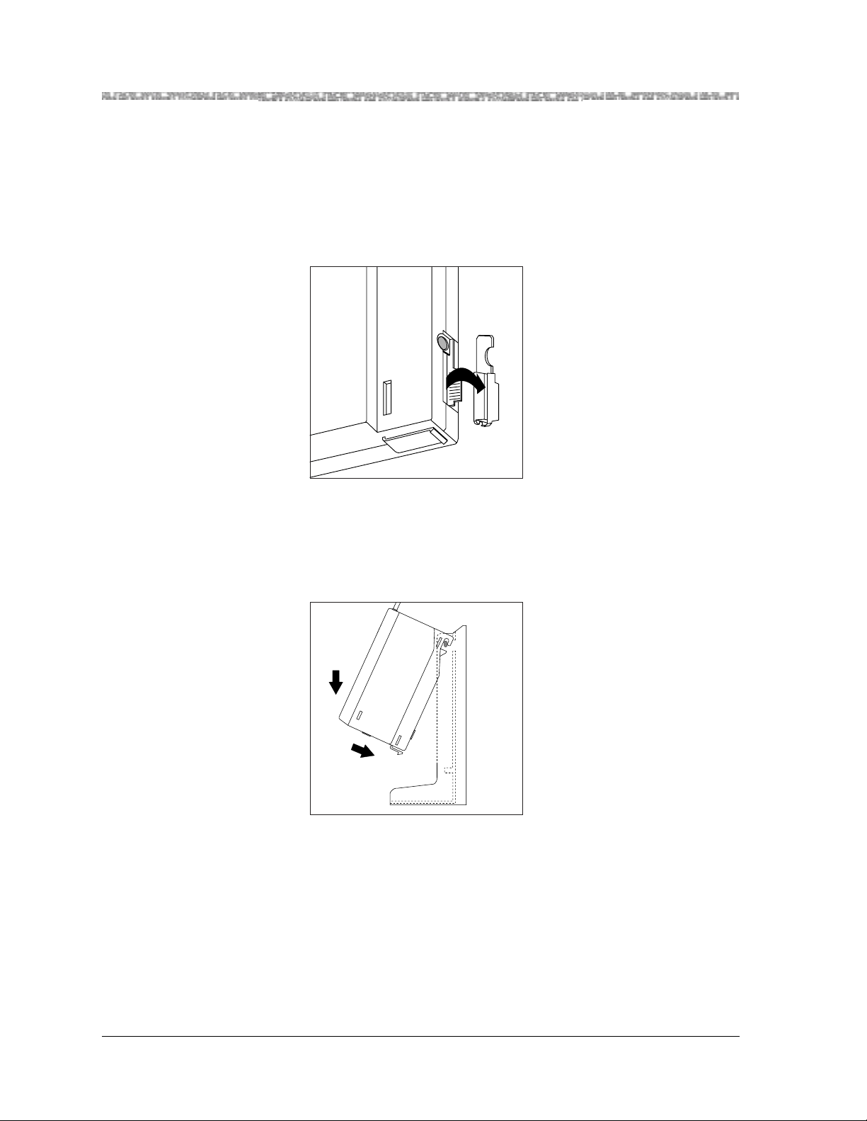
2 Installing the MDW 9031/9031DCP Pocket Phone Installing Multiple Carriers
Installing the Remaining Radio Modules
To install the remaining radio modules:
1 Power down the carriers.
2 Remove the plastic cap covering each radio module’s card edge before inserting
the radio modules into the carriers.
3 Beginning with the first empty slot and working from left to right, insert a radio
module into each slot of the control carrier. Hook each radio module onto a
mounting rod. Slowly swing the radio module’s card edge into the card edge
connector on the back of the carrier.
Note: Slot 6 of a Model 117A3 control carrier must always contain a radio
module to pass the synchronization signal to the next carrier.
A Model 117A4 carrier does not require Slot 6 to be filled.
MDW 9031/9031DCP Wireless Pocket Phone Installation and Use
503-801-16654 Issue 3 October 1999
Page 63
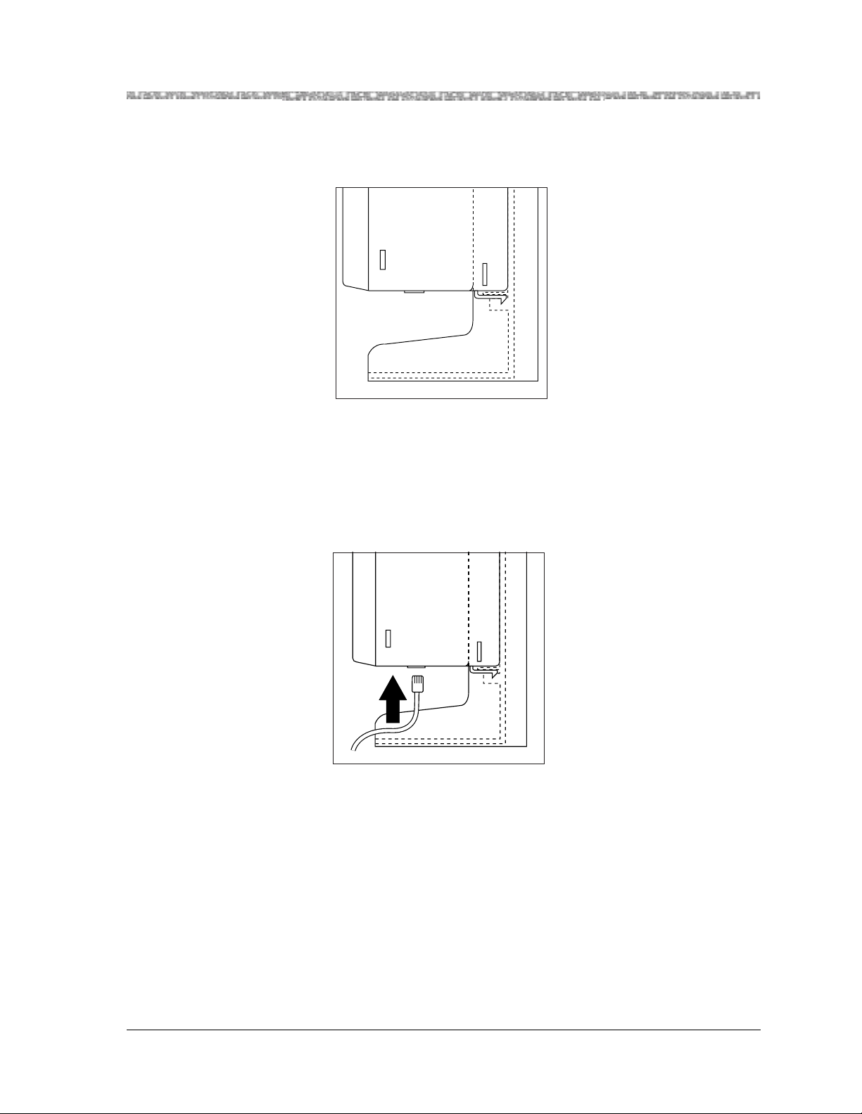
Installing Multiple Carriers Installing the MDW 9031/9031DCP Pocket Phone 2
4 When the card edge is fully seated, a snap lock on the bottom of the radio module
will engage.
5 Repeat Steps 3 and 4 for each expansion carrier, until each radio module is
inserted into a carrier.
Note: Fill all six slots of the current carrier before inserting radio modules into
the next carrier.
6 Insert a telephone line cord into the bottom of each radio module.
MDW 9031/9031DCP Wireless Pocket Phone Installation and Use
503-801-166 Issue 3 October 1999 55
Page 64

2 Installing the MDW 9031/9031DCP Pocket Phone Installing Multiple Carriers
MUSIC
ON
HOLD
N
S
I
O
N
S
X
T
E
N
S
I
O
N
S
7 Slide the telephone line cords through the cable manager slot on the left front of
the carrier.
8 Insert the free end of each telephone line cord into the appropriate extension jack
or terminal/station connector on your communications system switch/control unit
(refer to your communications system manual for the proper location).
PFT
L
I
N
PFT
E
L
S
I
N
PFT
E
L
PAGE
S
I
N
PFT
E
L
SMDR
S
I
N
PFT
E
L
S
I
N
206
MODULE
E
S
PFT
206
MODULE
PFT
PROCESSOR
E
MODULE
X
T
400
E
E
MODULE
X
N
T
S
400
VOL
E
MODULE
I
N
O
S
N
E
I
S
X
MUSIC
O
ON
T
HOLD
N
E
E
S
X
N
T
S
E
I
N
O
S
N
I
S
O
N
S
MDW 9031/9031DCP Wireless Pocket Phone Installation and Use
503-801-16656 Issue 3 October 1999
Page 65

Installing Multiple Carriers Installing the MDW 9031/9031DCP Pocket Phone 2
9 Power the carriers as follows:
If the carriers are plugged
into...
Then...
one surge suppressor strip Power the strip.
Result:
All the carriers will turn on simultaneously.
wall outlets Plug in the power for the carriers in this order:
T
!
CAUTION:
21
O N
1 2 3 4
Control
Carrier
1
RANSTALK
N
A
H
R
T
P
A
E
O
N
N
R
M
G
R
E
T
P
A
H
K
O
E
T
I
C
A
R
P
E
R
U
R
M
A
F
T
R
E
X
O
L
N
E
I
R
A
L
K
M
U
S
P
I
M
E
R
O
L
K
O
E
T
I
C
A
R
P
E
R
U
R
M
A
F
T
R
E
X
O
L
N
E
I
R
A
L
K
M
U
S
P
I
M
E
R
O
L
K
O
E
T
I
C
A
R
P
E
R
K
O
E
T
I
C
A
R
P
E
R
CAUTION
Y
L
N
O
E
E
S
L
U
21
B
A
C
6
T
9
&
8
O N
T
7
A
6
6
7
4
8
N
⁄
P
N
I
T
U
O
C
N
Y
S
F
O
T
U
O
5
1 2 3 4
6
Expansion
Carrier #1
T
RANSTALK
N
A
H
R
T
P
A
E
O
N
N
R
M
G
R
E
T
P
A
H
K
O
-
E
T
I
C
A
R
P
E
R
U
R
M
A
F
T
R
E
X
O
L
N
E
I
R
A
L
K
M
U
S
P
I
M
E
R
O
L
K
O
-
E
T
I
C
A
R
P
E
R
U
R
M
A
F
T
R
E
X
O
L
N
E
I
R
A
L
K
M
U
S
P
I
M
E
R
O
L
K
O
-
E
T
I
C
A
R
P
E
R
K
O
-
E
T
I
C
A
R
P
E
R
21
O N
CAUTION
Y
L
N
O
E
E
S
L
U
21
B
A
C
6
T
9
&
8
O N
T
7
A
6
6
7
4
8
N
⁄
P
N
I
T
U
O
C
N
Y
S
F
O
T
U
O
5
1 2 3 4
6
Expansion
Carrier #2
2 3
T
RANSTALK
N
A
H
R
T
P
A
E
O
N
N
R
M
G
R
E
T
P
A
H
K
O
E
T
I
C
A
R
P
E
R
U
R
M
A
F
T
R
E
X
O
L
N
E
I
R
A
L
K
M
U
S
P
I
M
E
R
O
L
K
O
E
T
I
C
A
R
P
E
R
U
R
M
A
F
T
R
E
X
O
L
N
E
I
R
A
L
K
M
U
S
P
I
M
E
R
O
L
K
O
E
T
I
C
A
R
P
E
R
K
O
E
T
I
C
A
R
P
E
R
21
O N
21
O N
5
21
CAUTION
O N
Y
L
N
O
E
E
S
L
U
B
A
C
6
T
9
&
8
T
7
A
6
6
7
4
8
N
⁄
P
N
I
T
U
O
C
N
Y
S
F
O
T
U
O
1 2 3 4
6
Expansion
Carrier #3
4
Never connect or disconnect expansion cables or telephone line cords, or
insert or remove radio modules, while the carrier is plugged into the wall
outlet.
10 Go to “Installation Self-Test for Remaining Radio Modules” (page 58).
T
RANSTALK
N
A
H
R
T
P
A
E
O
N
N
R
M
G
R
E
T
P
A
H
K
O
-
E
T
I
C
A
R
P
E
R
U
R
M
A
F
T
R
E
X
O
L
N
E
I
R
A
L
K
M
U
S
P
I
M
E
R
O
L
K
O
-
E
T
I
C
A
R
P
E
R
U
R
M
A
F
T
R
E
X
O
L
N
E
I
R
A
L
K
M
U
S
P
I
M
E
R
O
L
K
O
-
E
T
I
C
A
R
P
E
R
K
O
-
E
T
I
C
A
R
P
E
R
UTION
CA
Y
L
N
O
E
E
S
L
U
21
B
A
C
6
T
9
&
8
O N
T
7
A
6
6
7
4
8
N
⁄
P
N
I
T
U
O
C
N
Y
S
F
O
T
U
O
5
6
1 2 3 4
T
RANSTALK
N
A
H
R
T
P
A
E
O
N
N
R
M
G
R
E
T
P
A
H
K
O
-
E
T
I
C
A
R
P
E
R
U
R
M
A
F
T
R
E
X
O
L
N
E
I
R
A
L
K
M
U
S
P
I
M
E
R
O
L
K
O
-
E
T
I
C
A
R
P
E
R
U
R
M
A
F
T
R
E
X
O
L
N
E
I
R
A
L
K
M
U
S
P
I
M
E
R
O
L
K
O
-
E
T
I
C
A
R
P
E
R
K
O
-
E
T
I
C
A
R
P
E
R
TION
21
CAU
O N
Y
L
N
O
E
E
S
L
U
21
B
A
C
6
T
9
&
8
O N
T
7
A
6
6
7
4
8
N
⁄
P
N
I
T
U
O
C
N
Y
S
F
O
T
U
O
5
6
Expansion
Carrier #4
5
MDW 9031/9031DCP Wireless Pocket Phone Installation and Use
503-801-166 Issue 3 October 1999 57
Page 66

2 Installing the MDW 9031/9031DCP Pocket Phone Installing Multiple Carriers
Installation Self-Test for Remaining Radio Modules
To perform an installation self-test for the remaining radio modules:
1 Wait a few seconds after powering up the carriers, then verify that the carriers’
OUT OF SYNC LEDs are not lit.
OUT OF S YNC
CONTROL/
T
4
1 2 3 4
2 At this stage of your installation, again verify that the LEDs displayed match the
first or fourth lines of the SYNC and CONTROL/EXP LED Codes label,
depending on whether the carrier is the control or an expansion carrier. (Keep in
mind that a Model 117A3 carrier does not have a CONTROL/EXPANSION
LED.)
RANSTALK
21
O N
21
O N
5
EXPANSION
N
A
H
R
T
P
A
E
O
N
N
R
M
G
R
E
T
P
A
H
K
O
E
T
I
C
A
R
P
E
R
U
R
M
A
F
T
R
E
X
O
L
N
E
I
R
A
L
K
M
U
S
P
I
M
E
R
O
L
K
O
E
T
I
C
A
R
P
E
R
U
R
M
A
F
T
R
E
X
O
L
N
E
I
R
A
L
K
M
U
S
P
I
M
E
R
O
L
K
O
E
T
I
C
A
R
P
E
R
K
O
E
T
I
C
A
R
P
E
R
N
O
I
T
U
A
C
Y
L
N
O
E
E
S
L
U
B
A
C
6
T
9
8
&
T
7
6
A
6
7
4
8
N
⁄
P
N
I
T
U
O
C
N
Y
S
F
O
T
U
O
6
MDW 9031/9031DCP Wireless Pocket Phone Installation and Use
503-801-16658 Issue 3 October 1999
Page 67

Installing Multiple Carriers Installing the MDW 9031/9031DCP Pocket Phone 2
3 If an OUT OF SYNC LED is lit, power down, wait at least 15 seconds, and then
repower the carriers in order from left to right, as described in Step 9 in
“Installing the Remaining Radio Modules.” If the LED is still lit, follow the
suggestions in the “Installation Problems” section of Chapter 5,
“Troubleshooting.” If the LED is still lit, call Customer Support as described in
the Copyright and Legal Notices at the beginning of this book.
OUT OF S YNC
CONTROL/
T
4
1 2 3 4
4 The PASS and POWER LEDs on all radio modules should be lit and green,
indicating that all of the radio modules are functional. If a radio module’s PASS
LED is not lit:
RANSTALK
21
O N
21
O N
5
EXPANSION
N
A
H
R
T
P
A
E
O
N
N
R
M
G
R
E
T
P
A
H
K
O
E
T
I
C
A
R
P
E
R
U
R
M
A
F
T
R
E
X
O
L
N
E
I
R
A
L
K
M
U
S
P
I
M
E
R
O
L
K
O
E
T
I
C
A
R
P
E
R
U
R
M
A
F
T
R
E
X
O
L
N
E
I
R
A
L
K
M
U
S
P
I
M
E
R
O
L
K
O
E
T
I
C
A
R
P
E
R
K
O
E
T
I
C
A
R
P
E
R
N
O
I
T
U
A
C
Y
L
N
O
E
E
S
L
U
B
A
C
6
T
9
&
8
T
7
6
A
6
7
4
8
⁄N
P
N
I
T
U
O
C
N
Y
S
F
O
T
U
O
6
a Power down the carriers.
b From the wall outlet, unplug the power cord/AC adapter of the radio module
that did not light.
c Wait 15 seconds.
d Plug in the radio module’s power cord again.
e Repower the carriers, following the proper left-to-right order.
If the PASS LED is still not lit, follow the suggestions in the “Installation
Problems” section of Chapter 5, “Troubleshooting.” If the LED is still not lit,
call Customer Support as described in the Copyright and Legal Notices at the
beginnin g of this book.
POWER
RADIO
PASS
Radio
R
Module
E
W
O
P
IO
D
A
R
PASS
5 Go to “Handset” (page 60).
MDW 9031/9031DCP Wireless Pocket Phone Installation and Use
503-801-166 Issue 3 October 1999 59
Page 68

2 Installing the MDW 9031/9031DCP Pocket Phone Handset
Handset
This section explains how to install the handset battery pack, change the communications system setting, and fill
out the handset label.
Inserting and Removing the Handset’s Battery Pack
To insert and remove the battery pack:
1 To insert the battery pack into the handset, insert the two small rectangular tabs
located along the bottom back edge of the handset into the two rectangular holes
along the bottom front edge of the battery pack.
Rectangular tabs
2 Press the battery pack downward until it clicks into place.
The battery pack must be charged prior to using the ha ndset. See “Battery
Charger” later in this chapter for instructions.
Spring latch
MDW 9031/9031DCP Wireless Pocket Phone Installation and Use
503-801-16660 Issue 3 October 1999
Page 69

Handset Installing the MDW 9031/9031DCP Pocket Phone 2
3 To remove the battery pack, slide the spring latch upward (away from the battery
pack). While holding the latch up, grasp both sides of the battery pack, then
gently pull the battery pack upward and out.
Changing the Communications System Setting
The communications system you use determines what information the MDW 9031/9031DCP Pocket Phone can
display and how the phone lines and programmable/intercom/drop buttons are iden tif ied. ( Fo r the MDW 9031,
see the appropriate “Button Mapping” topics in the “MDW 9031 Compatibility” sectio n in Chapter 6. For the
MDW 9031DCP, see the “Button Mapping” topic in the “MDW 9031DCP Compatibility” section in Chapter 6.)
The MDW 9031 is factory-set to work with the PARTNER communications system. If you are using
P ARTNER as your communications system, skip this section; if you are using a different communications
system, you will need to change the setting.
The MDW 9031DCP is factory-set to work with the DEFINITY communications system.
T o change the commu nications system setting, us e the followin g procedure to enter Lo cal Mode and then Button
Mapping Mode:
1 Make sure the handset is turned off.
2 Press and hold the Select button ( " ) for three seconds.
3 While still holding ", press O.
The handset beeps twice, and the top line of the display shows LCL:P (unless you
have already changed it from the default setting).
MDW 9031/9031DCP Wireless Pocket Phone Installation and Use
503-801-166 Issue 3 October 1999 61
Page 70

2 Installing the MDW 9031/9031DCP Pocket Phone Handset
4 Press and hold “M” (6) for three seconds to enter Button Mapping Mode.
The handset display shows one of the following:
MAP:P PARTNER Systems
MAP:D DEFINITY Systems, System 25, System 75, and
System 85
Note: The MDW 9031DCP should only be set
to MAP:D for DEFINITY.
MAP:M1 All MERLIN Systems (except MERLIN 410
and MERLIN 820), including MERLIN LEGEND
MAP:M2 MERLIN 410 and MERLIN 820
5 Press " repeatedly to cycle through the settings until the display appropriate
for your communications system is shown.
6 Press O when the correct setting is displayed.
The top line of the display shows information appropriate to the communications
system you are using.
7 To verify your setting, repeat Steps 1–3. The top line of the display should appear
as follows, depending upon your communications system:
PARTNER Systems LCL:P
DEFINITY Systems, System 25, System 75, and
LCL:D
System 85
All MERLIN Systems (except MERLIN 410 and
LCL:M1
MERLIN 820), including MERLIN LEGEND
MERLIN 410 and MERLIN 820 LCL:M2
For a description of the button mapping between the MDW 9031/9031DCP Pocket
Phone and the wired telephones for your communications system, or to program
features on buttons, see the appropriate “Button Mapping” topics in Chapter 6.
MDW 9031/9031DCP Wireless Pocket Phone Installation and Use
503-801-16662 Issue 3 October 1999
Page 71

Handset Installing the MDW 9031/9031DCP Pocket Phone 2
EXT.
A
Filling Out the Handset Label
MDW 9031/9031DCP Pocket Phone display shows the s tatus of up to 12 lines or programmable/intercom/drop
buttons. Since the MDW 9031/9031DCP is compatible with s everal dif ferent communications systems , diagrams
of the button mappings for these systems are provided in Chapter 6.
Note: The MDW 9031DCP is compatible only with DEFINITY.
MDW 9031/9031DCP has a label on the back of the handset near the top where you can record:
• Your extens ion number.
• The mapping of your MDW 9031/9031DCP line buttons to those on a wired
phone for your communications system.
Note: Use a pencil or ballpoint pen on the label, in case you want to erase the
information later. Do not use felt-tip or other types of non-erasable
markers. Also, do not remove the label.
B
C
D
1
2
3
4
5
6
7
.
T
X
E
A
B
C
D
1
2
3
4
5
6
7
8
8
To fill out the handset label:
1 Write your extension number on the label.
2 Locate the section in Chapter 6 that describes the button mapping for your
communications system; then copy the mapping to the label for ease of reference.
3 Go to “Battery Charger” (page 64).
MDW 9031/9031DCP Wireless Pocket Phone Installation and Use
503-801-166 Issue 3 October 1999 63
Page 72

2 Installing the MDW 9031/9031DCP Pocket Phone Battery Charger
Battery Charger
This section explains how to choose a location for the battery ch arger and install it. It also explains how to insert
and remove a battery pack.
Positioning the Battery Charger
The battery charger can be placed on a desk, or it can be mounted on a wall. Before you install the battery
charger, note the following considerations:
• Locate the battery charger within 5 feet (1.6 m) of a properly grounded, 3-prong
electrical outlet that is not controlled by an on/off switch.
• If your communications system uses an uninterruptible power supply, such as a
backup generator, you may want to connect the battery charger to that power
supply.
• Do not locate the battery charger where it will be exposed to direct sunlight or
water.
!
WARNING:
The rechargeable battery pack may contain elements that are harmful to
the environment (for example, nickel). Do not burn or puncture the
battery. As with other batteries of this type, burning or puncturing could
release toxic material that could cause injury. Do not dispose of it in
household garbage. For information about recycling or proper disposal,
consult your local solid waste (garbage) collection or disposal
organization.
Installing the Battery Charger
• If you are wall-mounting the battery charger, follow Steps 1 through 7.
• If you are desk-mounting the battery charger, follow only Steps 1, 5, and 7.
To install the battery charger:
1 Check to make sure the battery charger’s power cord is unplugged from the wall
outlet before continuing. If you are desk-mounting, skip to Step 5.
2 To wall-mount, place the battery charger’s wall-mounting template (located on
the last page of this book) against the wall. Choose a location backed by a
wooden stud (if unavailable, use toggle bolts instead of the supplied wood
screws). Hold the template straight; use a level if needed.
3 Mark the locations for the two wall-mounting screws, and then remove the
template from the wall. Lightly tap a nail into the wall to start the holes.
4 Place the screw through the wall spacers so that the screw head nests in the
indentation on the spacer. Start the screws, and screw them in until the wall
spacers rest against the wall.
MDW 9031/9031DCP Wireless Pocket Phone Installation and Use
503-801-16664 Issue 3 October 1999
Page 73

Battery Charger Installing the MDW 9031/9031DCP Pocket Phone 2
5 Insert the battery charger’s power cord/AC adapter into the battery charger. If you
are desk-mounting the battery charger, skip to Step 7.
6 Place the keyhole-shaped openings in the back of the battery charger over the
screw heads and wall spacers, then slide the battery charger downward into the
groove in the wall spacers to lock it into place.
7 Plug the battery charger’s power cord/AC adapter into a properly grounded,
3-prong wall outlet that is not controlled by an on/off switch.
MDW 9031/9031DCP Wireless Pocket Phone Installation and Use
503-801-166 Issue 3 October 1999 65
Page 74

2 Installing the MDW 9031/9031DCP Pocket Phone Battery Charger
Inserting a Battery Pack into the Spare Batt ery Compartment
Slide the battery pack (or an optional extended battery pack) into the spare battery compartment until it is firmly
seated with the back of the battery pack against the back of the spare battery compartment. Do not force the
battery pack down. The battery pack should slide easily into the slot.
Correct positioning of the battery pack in the charger is important to ensure proper charging. The bottom end of
either battery pack also has two small round holes that must align with two guide pins on the bottom of the spare
battery compartment. When a battery pack is positioned correctly in the spare battery compartment, the SPARE
LED on the front of the battery charger lights.
The spare battery compartment has a vertical ridge on each side that serves as a “guide rail” for positioning the
standard battery pack.
Vertical Guide Rail
Standard Spare Battery
Pack
Spare Battery Pack Guide Pin
Battery Charger Contacts
Spare Battery Compartment
Handset Cradle
Vertical Guide Rail
SPARE LED
MDW 9031/9031DCP Wireless Pocket Phone Installation and Use
503-801-16666 Issue 3 October 1999
Page 75

Battery Charger Installing the MDW 9031/9031DCP Pocket Phone 2
The extended battery pack slides down into the spare battery compartment.
Extended Spare Battery Pack
Handset Cradle
Spare Battery Pack Guide Pin
Battery Charger Contacts
Spare Battery Compartment
SPARE LED
Removing a Battery Pack from the Spare Battery Compartment
To remove a battery pack from the spare battery compartment of the charger, lift the battery pack up and out.
MDW 9031/9031DCP Wireless Pocket Phone Installation and Use
503-801-166 Issue 3 October 1999 67
Page 76

2 Installing the MDW 9031/9031DCP Pocket Phone Battery Charger
Inserting the Handset into the Battery Charger’s Handset Cradle
Correct positioning of the handset in the charger is important to ensure proper charging:
1 Position the handset (with either battery pack attached) so that the two sm all
round holes in the bottom of the handset fit over the two guide pins on the bottom
of the handset cradle.
2 Rock the handset back into the cradle until it is firmly seated with the back of the
handset battery pack against the back of the handset cradle.
When the handset has been inserted correctly, the following occur:
• The HANDSET LED lights.
• If the handset was turned on, the ON icon in the display is no longer visible.
• Any call that was in progress is terminated.
• After 15 seconds, the handset enters the energy-saving “sleep” mode.
On/Off
R
e
d
ia
l
M
u
te
a
t/P
1
ABC
2
DEF
C
o
n
f
T
ra
n
s
H
o
ld
SPARE
3
GHI
4
JKL
5
MNO
6
PQRS
7
TUV
8
W
9
XYZ
O
0
PER
HANDSET
REFRESH
Guide Pins
F
e
HANDSET LED
Removing the Handset from the Handset Cradle
To remove the handset from the handset cradle, lift it out.
MDW 9031/9031DCP Wireless Pocket Phone Installation and Use
SPARE
HANDSET
Feat/P
Conf
Trans
Hold
On/Off
Redial
12
GHI
4
P
7
Q
R
Mute
ABC
DEF
3
JKL
5
MNO
6
S
TUV
8
W
9
X
Y
Z
O
0
P
E
R
REFRESH
503-801-16668 Issue 3 October 1999
Page 77

3 Using the MDW 9031/9031DCP
Pocket Phone
Important Safety Instructions
Please see “Important Safety Instructions” at the beginning of Chapter 2.
Handset
The MDW 9031/9031DCP Pocket Phone supports nor mal operation of all of the features of the switch as far as is
practical within the limitations of its reduced size and power and the nature of wireless operation. There are very
few differences in operation between the wireless MDW 9031/9031DCP Pocket Phone and a wired deskset.
This chapter describes the handset and how to use it. It also explains how to use a headset.
MDW 9031/9031DCP Wireless Pocket Phone Installation and Use
503-801-166 Issue 3 October 1999 69
Page 78

3 Using the MDW 9031/9031DCP Pocket Phone Handset
Handset Controls
Receiver
Headset On/Off
Press to turn the headset on if the
headset is plugged in.
ON
appears in handset display. To
turn off, press again. Turn on to
make or answer a call, and turn off
to “hang up.”
Lanyard Loop
Attach lanyard for carrying
handset.
Volume Control
Press “+” to increase or “-” to
decrease volume of receiver or
alerter.
On/Off
Press to turn the handset on.
ON
appears in handset display. To
turn off, press again. Turn on to
make or answer a call, and turn
off to “hang up.”
Feat/P
(Feature/Program)
Press to use dial-code features
(PARTNER
®
Systems only) or to
enter programming mode.
Exit (9031DCP Only)
Press the Feat/P twice to
Exit the Softkey menu.
Conf (Conference)
Press to conference in (add)
another party to your call.
Trans
(Transfer)
Press to transfer a call to
another extension.
Hold
Press to put a call on hold.
MSG
On/Off
Feat/P
Conf
Trans
Hold
212 555 1212
ON
65
234
1
AB
Redial
12
GHI
4
PQRS
78
CD
Mute
ABC
JKL
5
6
TUV
97
8
OPER
0
3
DEF
MNO
WXYZ
Receives the sound of your
caller’s voice, unless a
headset is connected.
Antenna
Extend fully or retract fully to
use handset. Extend fully to
maximize the handset range
and voice quality.
Handset Display
with Backlighting
Displays status of lines and
range. For a detailed
description, see “Handset
Display” later in this chapter.
Column
Use together with Select
button to choose a line or
programmable/intercom/
drop button.
Scroll (9031DCP Only)
When the Selection rectangle
is in the top row, press to
toggle between the first and
second line of the display.
Redial
Press to redial the last
number manually dialed
from the handset.
Select
Use to move the Selection
rectangle, and, together with
Column buttons, to choose
a line or programmable/
intercom/drop button. Also
use to wake-up the phone.
Mute
Press to turn the microphone
off for privacy.
Headset Connector
Plug in the headset adapter
to use the headset.
MDW 9031/9031DCP Wireless Pocket Phone Installation and Use
503-801-16670 Issue 3 October 1999
Page 79

Handset Using the MDW 9031/9031DCP Pocket Phone 3
Column and Select Buttons
The MDW 9031/9031DCP Pocket Phone can display the status of up to 10 lines/intercom/programmable
buttons, but the number of lines supported by compatible communications system switches varies. However, it
has only 4 selection buttons (the Column buttons). The Select button ( " ) is used in conjunction with the
Column buttons ( '’ ) to increase the available selections to 12. Each Column button ( '’ ) affects one of the
three lines or programmable/intercom/drop buttons directly above it, as shown in the illustration below.
ON
Each time you press the Select button ( " ), the Selection rectangle moves to another row (cycling through the
three rows in turn). The Column buttons ( '’ ) each represent one of the four lines or programmable/intercom/
drop buttons in the row enclosed by the Selection rectangle.
Selection rectangle
ON
For example, suppose your handset shows the Selection rectangle around the middle row of lines. If you press
the second Column button from the left (shaded in the illustration above), you select Line 2, as indicated by the
truncated triangle in the illustration.
Note: If you have a communications system other than PARTNER, the line you
select is indicated by a small rectangle instead of the triangle, as shown
below:
ON
See “Manually Selecting a Line or Programmed Button” and “Preselecting a Line” later in this chapter for more
information about the Column and Select buttons.
MDW 9031/9031DCP Wireless Pocket Phone Installation and Use
503-801-166 Issue 3 October 1999 71
Page 80

3 Using the MDW 9031/9031DCP Pocket Phone Handset
Handset Display (with Backlighting)
The MDW 9031/9031DCP Pocket Phone display has one 16-alphanu meric-ch aracter line an d fo ur lines of icons
to provide you with status information. The display provides Backlight i ng (a pr ogr a mmable op tio n) ei ther w hen
the handset is turned on or when the " button is pressed. See “Changing the Handset Setting.”later in this
chapter. The Backlighting lasts for 10 seconds, if no other button is pressed when the handset is turned on.
543
1
2
8
MSG ON
RANGE MUTE
6
7
9
Note: This illustration is intended to show you what all of the indicators look
like, but you will never see all of the line status indicators illuminated at
once.
1 This line of the display gives you the i nformation you would see o n a wired
system phone’s display, except that the time is not provided. The information
varies according to which communications system you are using. For example,
the display may show the current date, the number you are calling, or Caller ID
information (if the system supports this feature). This display line is also used for
feedback when testing and programming the handset. See “Display Messages”
later in this chapter for more information about messages.
2 MSG icon indicates that you have a message.
3 RANGE icon indicates that the handset is out of range or almost out of r ange.
The handset also beeps. For more information, see “Range Indicators” later in this
chapter.
4 ON icon indicates that the handset has been turned on by pressing O.
5 Battery icon flashes to indicate a low battery condition. The handset also emits 2
beeps. For more information, see “Low Battery Indicator” later in this chapter.
6 No Ring icon indicates that the alerter is disabled. If the alerter is enabled, no
icon is displayed.
7 MUTE icon indicates that the handset microphone was turned off by pressing
M.
8 Line Status Indicators show the status o f line or progr a mmab le/intercom/drop
buttons. See Chapter 6 for button-mapping information. Also see “Line Status
Indicators” later in this chapter.
9 Selection rectangle indicates the active row for line or
programmable/intercom/drop button selection. See “Column and Select Buttons”
earlier in this chapter.
MDW 9031/9031DCP Wireless Pocket Phone Installation and Use
503-801-16672 Issue 3 October 1999
Page 81

Handset Using the MDW 9031/9031DCP Pocket Phone 3
When the display is blank, the handset is either turned off or in the power-saving “sleep” mode. You can activate
the display and Backlighting (if programmed) by pressing O, turning the handset on, or by pressing " to
“wake it up.”
Display Messages The top line of the handset display uses up to 16 alphanumeric characters to provide
messages such as the following:
• LCL:P (or LCL:D, LCL:M1, or LCL:M2) indicates that the handset is in Local
Mode, and tells which communications system the button mapping is set to
emulate:
LCL:P PARTNER System s
LCL:D DEFINITY Systems, System 25, System 75, and
System 85
LCL:M1 All MERLIN Systems (except MERLIN 410
and MERLIN 820), including MERLIN LEGEND
LCL:M2 MERLIN 410 and MERLIN 820
• WIRELESS TEST indicates that the handset is in Wireless Test Mode; 1 through
10 are used to measure signal strength and voice quality in Wireless Test Mode.
• VIBR indicates that the vibrator is enabled to notify you of incoming calls.
• PSEL indicates that Line Preselection is enabled.
• PRESELECTION:ON or PRESELECTION:OFF is display ed wh en yo u en ter
Preselection Mode, and indicates the status of the Line Preselection option.
• CHANGE BUTTN MAP is an error message indicating that the handset is set
for the wrong communications system. See “Changing the Communications
System Setting” in Chapter 2 for instructions for changing the setting.
• MAP:P (or MAP:D, MAP:M1, or MAP:M2) is displayed when you enter
Button Mapping Mode, and indicates the communications system to which the
MDW 9031/9031DCP buttons are currently mapped:
MAP:P PARTNER Systems
MAP:D DEFINITY Systems, System 25, System 75, and
System 85
Note: The MDW 9031DCP should only be set
to MAP:D for DEFINITY.
MAP:M1 All MERLIN Systems (except MERLIN 410
and MERLIN 820), including MERLIN LEGEND
MAP:M2 MERLIN 410 and MERLIN 820
• RANGE is an error message indicating that the handset is not communicating
with its radio module. See Chapter 5, “Troubleshooting,” for help in resolving
this problem.
MDW 9031/9031DCP Wireless Pocket Phone Installation and Use
503-801-166 Issue 3 October 1999 73
Page 82

3 Using the MDW 9031/9031DCP Pocket Phone Handset
Line Status Indicators There are 12 status indicators; each one corresponds to a specific outside line or
programmable/intercom/drop button. (The function of these statu s in dicators varies,
depending on the communications system you are using—see the Button Mapping
topic for the appropriate communications system switch in Chapter 6, “MDW
9031/9031DCP Pocket Phone Compatibility.”) The status indicators show either a
truncated triangle or a rectangle, signifying the following activity:
For PARTNER Systems:
A rectangle ( ) is the equivalent of a red LED on a wired system phone.
A truncated triangle ( ) is the equivalent of a green LED on a wired system phone.
For all other Systems:
A rectangle ( ) is the equivalent of a green LED on a wired system phone.
A truncated triangle ( ) is the equivalent of a red LED on a wired system phone.
Range Indicators For maximum range and voice quality, always fully extend the antenna before placing
or answering a call. The antenna must be either fully retracted (for short range)
or fully extended (for maximum range) to use the Pocket Phone.
The handset provides an audible and a visual signal to alert you when the handset is
near the end of the range of the radio module. Depending on how far away the
handset is from the radio module, the signals function as follows:
• The handset emits two beeps and flashes the RANGE indicator continuously.
Out of optimal range. You have walked into an area that is near the end of the
operating range of the radio module. You can continue your conversation or
initiate a call, but you are likely to experience a degradation in voice quality.
• The handset emits five sets of beeps and displays the RANGE indicator.
Loss of communication link. You have walked into an area that is out of the
operating range of the radio module. You must bring the handset within range of
the radio module within several seconds or the handset will turn off. If the handset
turns off, it appears that your call was disconnected; however, it was only placed
on Hold. To talk with your party, move back toward the radio module, press
O, then proceed as you would for any call placed on Hold.
• When you try to make a call, the handset emits two beeps and flashes the
RANGE indicator twice; then the handset automatically turns off.
Cannot establish communication link. You are completely out of range of the
radio module. To make the call, move back towards the radio module and try
again.
Refer to Chapter 5, “Troubleshooting,” for additional information about out-ofrange conditions.
MDW 9031/9031DCP Wireless Pocket Phone Installation and Use
503-801-16674 Issue 3 October 1999
Page 83

Handset Using the MDW 9031/9031DCP Pocket Phone 3
Low Battery Indicator The standard battery pack has approximately three hours of continuous talk time after
being fully charged. The optional extended battery pack has approximately eight
hours of continuous talk time after being fully charged.
When the handset is On and the battery power is low, the handset will emit two beeps
and the Battery icon in the handset display will flash. When this occurs, you have
five minutes or less of talk time left. At this point, you can either:
• Complete your call, turn the handset off, and recharge the battery pack, or
• If you have a charged spare battery pack, place your call on Hold and replace the
handset battery pack with the spare battery pack. Wait 6 to 10 seconds, then turn
the handset on and proceed as you would for any call placed on Hold.
Note: When the battery power is low, the two beeps will sound each time either
O button is pressed until either the battery is drained or you replace
the battery. If you continue talking, the handset will turn off when the
battery pack is drained. Your call will be placed on Hold automatically so
that you can swap battery packs or pick up the call on another telephone.
Volume Control
To increase or decrease the volume of the handset alerter or the receiver (earpiece):
• Alerter: Press the “+” or the “-” button while the MDW 9031/9031DCP is awake
but turned off. If the display is dark (the phone is in “sleep” mode), press " to
wake it up, then press the “+” or the “-” button.
• Receiver: Press the “+” or the “-” button while the MDW 9031/9031DCP is
turned on.
+
–
+ and – Volume Control Buttons
Lanyard Loop
Carrying Your Pocket Phone
The MDW 9031/9031DCP Pocket Phone has a loop in the upper corner to accommodate the included lanyard.
You can attach the lanyard, as illustrated above, and slip the lanyard over your wrist to guard against dropping
the phone. A leather carrying case is also available s eparately (see “Ordering Replacement and Optional Parts” in
Chapter 4).
Each battery pack (standard or extended) also comes with its own detachab le clip that you can attach to the b ack
of the battery pack, enabling you to attach the phone to your belt or purse strap. Be sure to use the clip that
matches the battery pack; they are not interchangeable.
You have either a metal or a plastic carrying clip. Follow the app ropriate procedur e on the nex t page to attach the
clip to the battery pack.
MDW 9031/9031DCP Wireless Pocket Phone Installation and Use
503-801-166 Issue 3 October 1999 75
Page 84

3 Using the MDW 9031/9031DCP Pocket Phone Handset
Attaching the Metal Carrying Clips
To attach the metal carrying clip to the battery pack, do the following:
1 Remove the battery pack from the handset, as described in “Inserting and
Removing the Handset's Battery Pack” in Chapter 2.
Standard Spare
Battery Pack
Extended Spare
Battery Pack
2 Place the two metal tabs on the clip into the slots on the battery pack, with the
“hooks” toward the bottom of the battery pack.
3 Slide the clip toward the bottom of the battery pack to engage the hooks.
Attaching the Plastic Clips
4 Reinsert the battery pack in the handset, as described in “Inserting and Removing
the Handset’s Battery Pack” in Chapter 2.
To attach the plastic clips to the battery pack, do the following:
1 Remove the battery pack from the handset, as described in “Inserting and
Removing the Handset's Battery Pack” in Chapter 2.
2 Hold the battery pack so that the back of the battery pack is facing you.
3 Hold the carrying clip so that it looks like the letter “ T.”
MDW 9031/9031DCP Wireless Pocket Phone Installation and Use
503-801-16676 Issue 3 October 1999
Page 85

Handset Using the MDW 9031/9031DCP Pocket Phone 3
Standard Spare
Battery Pack
Extended Spare
Battery Pack
4 Latch the right edge of the clip into the corresponding groove on the inner side of
the battery pack.
5 Push the left edge of the belt clip and snap it into the corresponding groove on the
inner side of the battery pack.
6 Reinsert the battery pack in the handset, as described in “Inserting and Removing
the Handset’s Battery Pack” in Chapter 2.
Antenna
The MDW 9031/9031DCP Pocket Phone comes with a user-replaceable, flexible, retractable antenna. For
maximum range and voice quality, always fully extend the antenna before placing or answering a call. You can
receive a call (if you are within range of the radio module) without extending the antenna, but you may get a
RANGE indication. The antenna must be fully extended for optimal performance.
Changing the Handset Settings
You can use Local Mode to change the handset settings for these functions:
• Communications system button mapping
• Vibrator
MDW 9031/9031DCP Wireless Pocket Phone Installation and Use
503-801-166 Issue 3 October 1999 77
Page 86

3 Using the MDW 9031/9031DCP Pocket Phone Handset
• Line Preselection
• Backlighting
• Alerter
Local Mode also gives you access to Local Test Mode (which enables you to test the alerter, vibrator, and
display) and Wireless Test Mode (which enables you to test sound clarity, signal strength, and voice quality).
While in Local Mode, the MDW 9031/9031DCP can still receive notification of incoming calls.
To access Local Mode, use the following procedure:
1 Make sure the handset is turned off.
2 Press and hold the Select button ( " ) for three seconds.
3 While still holding ", press O.
The handset beeps twice, and the display shows the handset settings. For
example, the following display indicates that the handset:
~ Is using button mapping for a PARTNER switch.
~ Has the vibrator and Line Preselection enabled.
~ Has the alerter disabled.
Changing the Communications System Button Mapping Setting
Enabling or Disabling the Vibrator
4 To exit Local Mode, press O.
If the MDW 9031/9031DCP Pocket Phone is set to use the wrong communications
system, an error message saying CHANGE BUTTN MAP shows on the top line of
the handset display each time the O button is pressed. If you see this message, use
the procedure described in “Changing the Communications System Setting” in
Chapter 2 to specify the correct communications system setting.
The vibrator vibrates to alert you to an incoming call in situations where you do not
want to disturb others with an audible ring. You can enable or disable the vibrator
using the following procedure:
1 Make sure the handset is turned off.
2 Press and hold the Select button ( " ) for three seconds.
MDW 9031/9031DCP Wireless Pocket Phone Installation and Use
503-801-16678 Issue 3 October 1999
Page 87

Handset Using the MDW 9031/9031DCP Pocket Phone 3
3 While still holding ", press O.
The handset beeps twice, and the display shows the handset settings, indicating
that you are now in Local Mode. (While in Local Mode, the MDW
9031/9031DCP can still receive notification of incoming calls.)
If the vibrator is enabled, the VIBR icon appears in the display. For example:
ON
If the vibrator is disabled, no icon appears.
4 Press “V” (8) on the dialpad to enable or disable the vibrator.
5 Press O to exit Local Mode.
Note: Both the alerter and the vibrator can be disabled at the same time. In this
case the only notification you have of an inco ming call is that a line s tatus
indicator (a truncated triangle or a rectangle, depending on your
communications system) flashes in the display.
Enabling or Disabling Line Preselection
Line Preselection lets you choose the line or button you want to use before turning the
handset on. For example, suppose your phone is ringing but you want to pick up a call
that is holding on another line instead of the ringing call. In normal operation, the
communications system automatically connects you to th e ringing line as soon as yo u
turn on the handset. With Line Preselection enabled, you can select the line you want
to connect to before turning on the handset.
Notes: Enabling Line Preselection lets the user retrieve both lines of display by
pressing the Column button programmed for SCROLL, without turning
the handset “on.”
Under certain conditions, the communications system tries to turn on a
speaker; for example, if you use Line Preselection to select a button
programmed for speed-dialing. Since the MDW 9031/9031DCP Pocket
Phone has no speaker, the system causes the ON icon in the handset
display to flutter, and the handset emits a continuous double beep. You
must press O to complete the connection.
When Line Preselection is enabled, you do not have to use it; however
you cannot use it unless it is enabled.
To enable Line Preselection, use the following procedure:
1 Make sure the handset is turned off.
2 Press and hold the Select button ( " ) for three seconds.
MDW 9031/9031DCP Wireless Pocket Phone Installation and Use
503-801-166 Issue 3 October 1999 79
Page 88

3 Using the MDW 9031/9031DCP Pocket Phone Handset
3 While still holding ", press O.
The handset beeps twice, and the display shows the handset settings, indicating
you are in Local Mode. (While in Local Mode, the MDW 9031/9031DCP can still
receive notification of incoming calls.)
If Line Preselection is enabled, PSEL appears on the top line of the display. For
example:
If Line Preselection is disabled, no icon appears.
4 Press and hold “P” (7) for three seconds.
The handset display shows PRESELECTION:ON if Line Preselection is
enabled or PRESELECTION:OFF if Line Preselection is disabled. For
example:
Enabling or Disabling Backlighting
5 To toggle between ON and OFF to enable or disable Line Preselection, press ".
6 To exit Local Mode, press O.
Backlighting for the display is factory set to ON for the MDW 9031/9031DCP Pocket
Phone. To toggle the Backlighting features OFF (and ON), use the following
procedure:
1 Make sure the handset is turned off.
2 Press and hold the Select button ( " ) for three seconds.
3 While still holding ", press O.
The handset beeps twice, and the display shows the handset settings, indicating
you are in Local Mode. (While in Local Mode, the MDW 9031/9031DCP can still
receive notification of incoming calls.)
a Press “L” (5) for “Lighting.” The Backlighting toggles ON or OFF each time
you press the 5.
b After setting the correct Backlighting state, press O for normal Pocket
Phone use.
MDW 9031/9031DCP Wireless Pocket Phone Installation and Use
503-801-16680 Issue 3 October 1999
Page 89

Handset Using the MDW 9031/9031DCP Pocket Phone 3
Enabling or Disabling the Alerter
The alerter is an audible signal to notify you of an incoming call. If a call comes in
while the phone is idle, the handset rings. If you are already on a call, the handset
chirps softly. You can adjust the volume of the alerter by pressing the “+” button or
the “-” button on the side of the handset when the phone is turned off. You can en able
or disable the alerter using the following procedure:
1 Make sure the handset is turned off.
2 Press and hold the Select button ( " ) for three seconds.
3 While still holding ", press O.
The handset beeps twice, and the display shows the handset settings, indicating
you are in Local Mode. (While in Local Mode, the MDW 9031/9031DCP can still
receive notification of incoming calls.)
If the alerter is disabled, the No Ring icon (a bell with a line through it) appears in
the second line of the display. For example:
ON
If the alerter is enabled, the icon is not displayed. For example:
ON
4 Press “A” (2) on the dialpad to enable or disable the alerter.
5 Press O to exit Local Mode.
Note: Both the alerter and the vibrator can be disabled at the same time. In this
case the only notification you have of an inco ming call is that a line s tatus
indicator (a truncated triangle or a rectangle, depending on your
communications system) flashes in the display.
MDW 9031/9031DCP Wireless Pocket Phone Installation and Use
503-801-166 Issue 3 October 1999 81
Page 90

3 Using the MDW 9031/9031DCP Pocket Phone Handset
Test Modes
You can use Local Test Mode and Wireless Test Mode to verify that your handset is working properly and that
the MDW 9031/9031DCP System is performing optimally.
Using Local Test Mode
You can use Local Test Mode to activate the audio warning signal, the vibrator, and all visual indicators on the
handset display, enabling you to test the following:
• Does the audio warning signal work?
• Does the vibrator vibrate?
• Is the display operational?
• Are the visuals bright and clear?
Note: While in Local Test Mode, the MDW 9031/9031DCP cannot make or
receive calls.
To use Local Test Mode:
1 Make sure the handset is turned off.
2 Press and hold the Select button ( " ) for three seconds.
3 While still holding ", press O.
The handset beeps twice, and the display shows the handset settings, indicating
you are in Local Mode. (While in Local Mode, the MDW 9031/9031DCP can still
receive notification of incoming calls.)
4 Press # to enter Local Test Mode.
The handset emits two beeps, the vibrator vibrates, and all indicators on the
display appear (including the rectangles and truncated triangles), as shown below.
Local Test Mode
RANGE MUTE
MSG
ON
If the beeps do not sound, the vibrator does not vibrate, or the indicators do not
appear, repeat Steps 1–4. If you still have problems, call for custom er supp ort as
described on the inside front cover of this book.
5 To exit both Local Test Mode and Local Mode, press O once.
Note: You must exit Local Test Mode to reinstate proper call handling.
MDW 9031/9031DCP Wireless Pocket Phone Installation and Use
503-801-16682 Issue 3 October 1999
Page 91

Handset Using the MDW 9031/9031DCP Pocket Phone 3
Using Wireless Test Mode
You can determine sound clarity, signal strength, and voice quality using Wireless Test Mode.
Y o u should use Wireless Test Mode to help you locate the best place to install the radio module(s) to optimize the
performance of your MDW 9031/9031DCP Pocket Phone. Repeat the tests several times, with the radio module
positioned in a different location each time.
By performing the tests as you walk around the area in which the handset will be used, you can determine the
handset’s range and the voice quality throughout the area of coverage. To perform the tests, all you need is an
electrical outlet for the radio module and a charged battery pack in the handset. You can perform the tests
multiple times and in any order; and you can exit at any time by pressing O.
Note: Ignore anything that displays if yo u pres s 4 wh ile in Wireless Test Mode.
These displays are for Lucent Technologies technicians’ use only.
To use Wireless Test Mode:
1 Make sure the handset is turned off.
2 Press and hold the Select button ( " ) for three seconds.
3 While still holding ", press O.
The handset beeps twice, and the display shows the handset settings, indicating
you are in Local Mode. (While in Local Mode, the MDW 9031/9031DCP can still
receive notification of incoming calls.)
4 Press “W” (9) to enter Wireless Test Mode.
WIRELESS TEST appears on the top line of the handse t di splay.
ON
The handset beeps twice and, if the vibrator is enabled, it vibrates; then you hear a
simulated dial tone. This dial tone continues until you exit Wireless Test Mode.
While in this mode, the MDW 9031/9031DCP cannot make or receive calls.
5 To identify the matching radio module for this handset, press 3.
The display indicates in which slot in the individual carrier (SLOT: n) the
matching radio module is located, using a number ( n) from 1 to 6. A stand-alone
radio module is shown as 0. For example, the display below shows a radio
module in slot 4:
ON
MDW 9031/9031DCP Wireless Pocket Phone Installation and Use
503-801-166 Issue 3 October 1999 83
Page 92

3 Using the MDW 9031/9031DCP Pocket Phone Handset
6 To determine sound clarity, listen to the simulated dial tone as you walk around.
A clear, steady tone indicates good sound clarity.
7 To determine signal strength, press 1.
The display shows the signal strength (SIG) for both the handset (HS) and the
base (B) (the radio module) at the moment that 1 was pressed, using a number
from 1 to 10, as shown in the following display:
ON
The higher the number, the stronger the signal, as shown in the following table.
You can press 1 again to show a subsequent signal-strength reading. Each time
you press 1, you get a new reading.
Display Number Signal Strength Is
10 Strong
9 Strong
8 Strong
7 Very Good
6 Very Good
5 Good
4 Good to Fair
3 Fair
2 Near end of range
1 Near end of range/loss of link
8 To determine voice quality, press 2.
The display shows the voice quality (QUAL) for both the handset (HS) and the
base (B) (the radio m odule) using a number from 1 to 10, as shown in the
following display:
ON
MDW 9031/9031DCP Wireless Pocket Phone Installation and Use
503-801-16684 Issue 3 October 1999
Page 93

Handset Using the MDW 9031/9031DCP Pocket Phone 3
The higher the number, the better the voice quality, as shown in the table below . A
low number may indicate potential interfering devices (such as another radio
transmitter) in the area. You can press 2 again to show a subsequent voicequality reading. Each time you press 2, you get a new reading.
Display Number Voice Quality Is
10 Very Good
9 Very Good/almost error free
8 Errors, but not noticeable in normal
speech
7 Errors, but not noticeable in normal
speech
6 Noticeable noise
5 Noticeable noise
4 Noisy but intelligble speech
3 Noisy but intelligible speech
Performance /Range Test in Wireless Test Mode
2 Garbled speech
1 Unintelligible speech
9 To determine power level, press 5.
The display shows the power level to which the handset (HS) and the base (B)
(the radio module) have adjusted. The power level adjusts from low power (1) to
high power (8) as the Pocket Phone is moved farther from its base. The following
display shows the Pocket Phone at its highest setting:
ON
10 To exit Wireless Test Mode and Local Mode, press O.
Using the signal-strength test and the voice-quality test together, you can determine:
• if the installation has been done correctly.
• if the handsets and bases are working properly.
• the range in which your MDW 9031/9031DCP Pocket Phone performs best at
your site.
MDW 9031/9031DCP Wireless Pocket Phone Installation and Use
503-801-166 Issue 3 October 1999 85
Page 94

3 Using the MDW 9031/9031DCP Pocket Phone Handset
Close Up Test
At no more than 5 to 10 feet (1.5 to 3.1 m) from its radio module, use the following
procedure:
1 Make sure the handset is turned off.
2 Press and hold the Select button ( " ) for three seconds.
3 While still holding ", press O.
The handset beeps twice, and the display shows the handset settings, indicating
you are in Local Mode. (While in Local Mode, the MDW 9031/9031DCP can still
receive notification of incoming calls.)
4 To enter Wireless Test Mode, press “W” (9).
Note: In a multiple TransTalk installation, put all of the handsets in
Wireless Test Mode at the same time. This allows you to observe
if all handsets are working properly together.
WIRELESS TEST appears on the top line of the handset di splay. The handset
beeps twice and vibrates, then you hear a simulated dial tone. This dial tone
continues until you exit Wireless Test Mode. While in this mode, the MDW
9031/9031DCP cannot make or receive calls. For more information, see “Using
Wireless Test Mode” in Chapter 3.
For all sets, do the following:
5 Press 1.
The display should show a 9 or 10 for signal strength (an occasional 8 is
acceptable). If it does not, see Chapter 5, “Troubleshooting,” for help with range
problems.
6 Press 2.
The display should show a 9 or 10 for voice quality (an occasional 8 is
adaptable). If it does not, see Chapter 5, “Troubleshooting,” for help with range
problems and/or voice quality problems.
Note: If you are seeing numbers lower than 8–10 for either signal strength or
voice quality while performing the Close Up Test, please refer to either
the “Installing a Single Carrier” section or “Installing Multiple Carriers”
section in Chapter 2, or Chapter 5, “Troubleshooting.” This will ensure
that your installation meets all installation and environmental
requirements.
Edge of Range Test
1
Periodically check the signal strength and voice quality as you walk away from
the radio module. Each time you press 1 or 2, you get a new reading.
When you see a signal strength of 3 at a power level of 8, you are at the “edge of
range” for the MDW 9031/9031DCP Pocket Phone. The distance will vary
depending on the environment, building s tructure, and other factors. The range in
an average office building is 500 to 700 feet (152.5 to 213.5 m). If, however,
dense walls intervene, the distance could be less.
MDW 9031/9031DCP Wireless Pocket Phone Installation and Use
503-801-16686 Issue 3 October 1999
Page 95

Handset Using the MDW 9031/9031DCP Pocket Phone 3
2 With a signal strength of 3, press 2 to check the voice quality. When the voice
quality is 7 or 8, the voice connection should be satisfactory. This is the edge of
your usable range.
The following diagram illustrates this Performance/Range test.
Go to either of the following sections:
• If installing one MDW 9031/9031DCP Pocket
• If installing one or more carriers, go to
“Waking Up” the Phone
Close-Up Test
5 to 10 feet (1.5 to 3.1 m)
Signal Strength = 9 to 10
Voice Quality = 9 to 10
*Edge-of-Usable-Range Test
Signal Strength = 3
Voice Quality = 7 to 8
*At High Power—Power Level = 8
POWER
RADIO
PASS
Radio
Module
Phone, go to “Installing a Single Radio Module” in
Chapter 2.
“Understanding Carriers” in Chapter 2.
In addition to “On” and “Off,” the MDW 9031/9031DCP has an energy-saving “sleep” or “standby” mode. The
MDW 9031/9031DCP “goes to sleep” 15 seconds after activity ceases (that is, after an alert stops ringing or after
you hang up).
The O and " buttons “wake up” the phone. The headset and handset O buttons turn the phone on, and
the Select button ( " ) signals the phone that activity is occurring. You can activate the display to see whether
you have a message or to check whether your alerter is enabled without actually turning the phone on (if the
communications system is very busy, for instance) by pressing ".
MDW 9031/9031DCP Wireless Pocket Phone Installation and Use
503-801-166 Issue 3 October 1999 87
Page 96

3 Using the MDW 9031/9031DCP Pocket Phone Handset
Making a Call
To make a call using your MDW 9031/9031DCP, use the following procedure:
1 Press the handset O button (or the headset O button if you have the
headset attached) to turn the phone on.
~ The MDW 9031/9031DCP seizes an available line and a truncated triangle or a
small rectangle (depending on your communications system) appears around
that line in the handset display.
~ You hear a dial tone.
2 Dial the call as you would on a wired system phone.
3 To end the call, press the O button.
After 15 seconds, unless there is other activity on the phone, the handset goes into
the energy-saving “sleep” mode.
Answering a Call
When you receive a call on your MDW 9031/9031DCP Pocket Phone, you hear a ringing tone if your alerter is
enabled, or you feel a vibration in the handset if the vibrator is enabled, or both. To answer the call, use the
following procedure:
1 Press the handset O button (or the headset O button if you have the
headset attached) to turn the phone on.
You are automatically connected to the ringing line.
2 Speak into the handset to converse with your caller.
3 To end the call, press the O button.
After 15 seconds, unless there is other activity on the phone, the handset goes into
the energy-saving “sleep” mode.
Manually Selecting a Line or Programmed Button
When you are making or answering a call, the MDW 9031/9031DCP automatically selects the line for you. In
some situations, however , you may want to se lect a particular line (for example, to u se an “800” line) . To select a
particular line or programmable/intercom/drop button, use the following procedure:
1 Press O.
The ON icon displays steadily, and you are connected to an available line.
2 If the Selection rectangle in the handset display is not surrounding the row that
includes the line or button you want to use, press " one or more times until the
rectangle encloses that row. (See “Column and Select Buttons” earlier in this
chapter for more information.)
3 Press the '’ button that cor responds to the line or button within the Selection
rectangle that you want to select.
You are connected to the line or you have access to the button you chose.
MDW 9031/9031DCP Wireless Pocket Phone Installation and Use
503-801-16688 Issue 3 October 1999
Page 97

Handset Using the MDW 9031/9031DCP Pocket Phone 3
To deselect the line or button, press O.
For information about assigning features to buttons, see “Programming Features for PARTNER, MERLIN, and
MERLIN LEGEND Systems” in Chapter 6.
Preselecting a Line
You may sometimes want to select a line other than the line to which the communications system automatically
connects you. To preselect a line, you must first enable Line Preselection. See “Enabling or Disabling Line
Preselection” earlier in this chapter.
Once Line Preselection is enabled, use the following procedure:
1 If the handset is “asleep,” press " to wake it up and activate the display.
2 If the Selection rectangle in the handset display is not surround ing the row that
includes the line you want to use, press " repeatedly un til the rectangle enclo ses
that row. (See “Column and Select Buttons” earlier in this chapter for more
information.)
3 Press the '’ button that corresponds to the line within the Selection rectangle
that you want to select.
The ON icon flashes in the display and the handset emits double beeps.
4 Press O.
The ON icon displays steadily, and you are connected to the line you chose.
Accessing Certain Voice Mail Systems with a DEFINITY System
Note: This section only applies to the MDW 9031 Pocket Phone.
After dialing into some voice mail systems (for example, Octel 200/250, 300/350),
the MDW 9031 Pocket Phone may not provide touch tones in order to access the
voice mail system prompts. If you experience this problem after dialing into your
voice mail system, press the
/ button twice. After pressing the / button
twice, your Pocket Phone will generate touch tones and you will be able to navigate
within your voice mail system. When you end your call to you r vo ice mail system, o r
press any non-dialpad button on your Pocket Phone (that is, Conf, Trans, Hold,
Redial, Mute), your MDW 9031 will stop generating touch tones behin d the voice
mail system. You will need to re-enter
/ whenever you dial into these voice mail
systems or after you have pressed a non-dialpad button.
Using a Headset
Lucent Technologies offers the Supra 9031 headset, which is specifically designed for use with your MDW
9031/9031DCP wireless phone or the Radium (over-the-ear) headset. A headset assists in call answering and
provides hands-free operation.
For ordering information, see “Ordering Replacement and Optional Parts” in Chapter 4.
MDW 9031/9031DCP Wireless Pocket Phone Installation and Use
503-801-166 Issue 3 October 1999 89
Page 98

3 Using the MDW 9031/9031DCP Pocket Phone Handset
!
CAUTION:
Plug ONLY the Supra 9031 headset cord or the Radium headset cord into the
headset adapter.
Note: Calls cannot be heard on the handset receiver when the headset is
plugged in to the headset adapter. The handset microphone is also
deactivated. The range of the handset is slightly diminished when you are
using a hea dset. You may need to move cl oser to the r adio module or
move the radio module closer to you.
If desired, you can disconnect the headset from the handset without dropping the call, either by unplugging the
headset adapter from the handset or by releasing the Quick Disconnect plug from the headset adapter cord. You
can then use the handset as you normally would.
Using the Headset On/Off Button
The headset On/Off button near the antenna becomes active only when the headset is
plugged into the headset connector. The headset On/Off button is identical in function
to the O button near the dialpad.
Answering Calls with a Headset
When you receive a call, you will hear a ringing tone or feel a vibration coming from
the handset (you will not hear a tone from the headset itself).
To answer a call:
1 Press either the headset On/Off button near the antenna or the O button near
the dialpad.
Placing Calls with a Headset
To place a call with a headset:
1 Press the On/Off button near the antenna or the O button near the dialpad to
access an available line.
The microphone and earpiece in the handset are disabled.
2 Dial the call as you would on a wired system phone.
3 Press either the On/Off button near the antenna or the O button near the
dialpad to end the call.
MDW 9031/9031DCP Wireless Pocket Phone Installation and Use
503-801-16690 Issue 3 October 1999
Page 99

Battery Charger Using the MDW 9031/9031DCP Pocket Phone 3
Battery Charger
The battery charger charges battery packs in the spare battery compartment and in the handset. If bo th are present
at the same time, charging in the spare battery compartment is suspended until the battery pack in the handset is
fully charged. To enable extended phone usage, you should purchase an extra battery pack and store it in the
charger, so that you always have a charged battery pack to switch to, if necessary. This section describes the
battery charger and explains how to use battery packs properly.
Spare Battery
Compartment
Guide Rai
Spare Battery
Guide Pin
Spare Battery
Compartment
Battery Contacts
Spare Battery
Compartment
l
Note: Do not touch, push, or pull any exposed battery contacts.
Battery Charger Features
The battery charger offers these features:
• The spare battery compartment refreshes the battery pack automatically by
fully discharging it before recharging it. This process reduces or eliminates the
potential “memory” effect. Memory effect, which reduces a battery’s capacity,
occurs over time when you repeatedly recharge a battery before it is fully
discharged.
Handset
Cradle
REFRESH Button
REFRESH LED
Handset Cradle
Battery Contacts
HANDSET LED
SPARE LED
• The handset cradle charges a battery pack in the handset.
• The REFRESH button, when pressed, refreshes the handset battery pack in the
handset cradle by fully discharging the battery pack before recharging it.
• The REFRESH LED and the HANDSET LED light when the REFRESH
button is pressed and stay lit until the battery pack finishes discharging.
• The HANDSET LED, when lit, indicates that the handset battery pack is installed
in the handset, and the handset is in the handset cradle.
• The SPARE LED, when lit, indicates that a battery pack is in the spare battery
compartment.
Note: Before you use the MDW 9031/9031DCP Pocket Phone handset for the
first time, the battery pack must be charged.
MDW 9031/9031DCP Wireless Pocket Phone Installation and Use
503-801-166 Issue 3 October 1999 91
Page 100

3 Using the MDW 9031/9031DCP Pocket Phone Battery Charger
The color of the battery charger’s LEDs indicates the state of the corresponding battery pack, as shown in the
following table:
If it is the SP ARE LED,
the battery pack in
Battery charger
LED shows...
Steady orange Is charging Is charging N/A
Steady green Is fully charged Is fully charged N/A
Flashing red
See Note below.
Steady red Is in the Discharge
Note: If either the SPARE LED or the HANDSET LED is flashing red, both batt ery packs must be
removed from the charger to clear the flashing-red condition. Address the possible problems
for one battery pack at a time to determine whether one is bad.
Note: The SPARE LED may turn amber instead of red when jostled in the spare battery charging
compartment. Remove the battery then place it back into the charger to clear the condition.
the spare battery
compartment...
Has one of the following
problems:
Is not seated properly in
the charger
Has dirty contacts
Is defective
portion of the Refresh
cycle
If it is the HANDSET
LED, the battery pack
in the Handset...
Has one of the following
problems:
Is not seated properly in
the charger
Has dirty contacts
Is defective
Is in the Discharge
portion of the Refresh
cycle
If it is the REFRESH LED,
the Refresh button was
pressed, and the Handset
battery pack...
N/A
Is in the Discharge portion of
the Refresh cycle
Extending Battery Life
The battery charger will charge a battery pack in the handset if you simply insert the handset in the battery
charger’s handset cradle; however, the Refresh process fully discharges the battery pack before recharging it,
thereby ensuring the best possible charge and the longest talk time.
“Memory effect” reduces a battery's capacity and can occur when you repeatedly recharge a battery pack before
it is fully discharged. The nickel metal hydride battery pack shipped with your MDW 9031/9031DCP is resistant
to the memory effect. Even so, it is recommended that you refresh your battery pack at least once a week.
The following table shows how long refreshing takes using a Model 40B charger, depending on how much
charge is left in the battery pack when you insert it into the charger and press the REFRES H button:
Battery Pack Battery-Pack Charge State
Standard Battery
Pack
Extended Battery
Pack
Low charge (Battery icon is lit) 0.5 hours 1.25 hour 1.75 hours
Full charge 3 hours 1.25 hour 4.25 hours
Low charge (Battery icon is lit) 0.5 hours 3.25 hours 3.75 hours
Full charge 8 hours 3.75 hours 11.75 hours
MDW 9031/9031DCP Wireless Pocket Phone Installation and Use
Discharge
Time
Recharge
Time Total Time
503-801-16692 Issue 3 October 1999
 Loading...