

Page 1

MAX 6000/3000 Network Configuration Guide
Part Number: 7820-0 629-002
For software version 8.0.1
March 2000
Page 2

Copyright© 2000 Lucent Technologies. All rights reserved.
This material is protected by the copyright laws of the United States and other countries. It may not be reproduced, distributed, or altered in any fashion by any
entity (either internal or external to Lucent Technologies), except in accordance with applicable agreements, contracts, or licensing, without the express
written consent of Lucent Technologies. For permis sion to reproduce or distribute, plea se em ai l your request to techpubs@ascend.com.
Notice
Every effort was mad e to en sur e that the information in this document was complete and accu ra te at the time of printing, but inf or ma tion is subject to change.
Security Statement
In rare instances, unauthorized individuals make connections to the telecommunica tions network through the use of acce ss fea tures.
Trademarks
MAX 6000, MAX 3000 are t rademarks of L ucent Technologies. Other trad emarks and tr ade names men tioned in this pub lication bel ong to thei r respective
owners.
Ordering Information
You can order the most up-to-date product information and com puter-based training online at http://www.lucent.com/ins/bookstore.
Feedback
Lucent Technologies appreciates your co mm e nts, either positive or negative, about this manual. Please send t hem to techpubs@ascend.com.
Lucent Technologies
Page 3

Customer Service
Customer Service provides a variety of options for obtaining information about Lucent
products and services, software upgrades, and technical assistance.
Finding information and software on the Internet
Visit the Web site at http://www.lucent.com/ins for technical information, product
information, and descriptions of available services.
Visit the FTP site at ftp://ftp.ascend.com for software upgrades, release notes, and
addenda.
Obtaining technical assistance
You can obtain technical assistance by telephone, email, fax, modem, or regular mail, as well
as over the Internet.
Gathering information you will need
If you need to contact Lucent for help with a problem, make sure that you have the following
information when you call or that you include it in your correspondence:
• Product name and model
• Software and hardware options
• Software version
• If supplied by your carrier, Service Profile Identifiers (SPIDs) associated with your line
• Your local telephone company’s switch type and operating mode, such as AT&T 5ESS
Custom or Northern Telecom National ISDN-1
• Whether you are routing or bridging with your Lucent product
• Type of computer you are using
• Description of the problem
Calling Lucent from within the United States
In the U.S., you can take advantage of Priority Technical Assistance or an Advantage service
contract, or you can call to request assistance.
Priority Technical Assistance
If you need to talk to an engineer right away, call (900) 555-2763 to reach the Priority Call
queue. The charge of $2.95 per minute does not begin to accrue until you are connected to an
engineer. Average wait times are less than 3 minutes.
Advantage Services
Advantage Services is a comprehensive selection of services. Installation services help get
your Lucent Wide Area Network (WAN) off to the right start. Ongoing maintenance and
MAX 6000/3000 Network Configuration Guide iii
Page 4

support services provide hardware and software solutions to keep your network operating at
peak performance. For more information, call (800) 272-3634.
Other telephone numbers
For a menu of Lucent’s services, call (800) 272-3634. Or call (510) 769-6001 for an operator.
Calling Lucent from outside the United States
You can contact Lucent by telephone from outside the United States at one of the following
numbers:
Telephone outside the United States (510) 769-8027
Austria/Germany/Switzerland
Benelux
France
Italy
Japan
Middle East/Africa
Scandinavia
Spain/Portugal
UK
For the Asia-Pacific region, you can find additional support resources at
http://www.lucent.com/ins/international/apac/.
Obtaining assistance through correspondence
Send your technical support questions to one of the following email addresses, or correspond
by fax, BBS, or regular mail with Customer Service in Lucent’s U.S. offices in Alameda, CA:
• Email from within the U.S.—support@ascend.com
• Email from Europe, the Middle East, or Africa—EMEAsupport@ascend.com
• Email from the Asia-Pacific region—apac.support@ascend.com
• Fax—(510) 814-2312
• Customer Support BBS (by modem)—(510) 814-2302
• Write to Lucent at the following address:
Attn: Customer Service
Lucent Technologies
1701 Harbor Bay Parkway
Alameda, CA 94502-3002
USA
(+33) 492 96 5672
(+33) 492 96 5674
(+33) 492 96 5673
(+33) 492 96 5676
(+81) 3 5325 7397
(+33) 492 96 5679
(+33) 492 96 5677
(+33) 492 96 5675
(+33) 492 96 5671
iv MAX 6000/3000 Network Configuration Guide
Page 5

Contents
Customer Service..................................................................................................................... iii
About This Guide........................................................................... xxv
How to use this guide............................................................................................................. xxv
What you should know ......................................................................................................... xxvi
Documentation conventions................................................................................................ xxvii
MAX 6000/3000 Series documentation set....................................................................... xxviii
Chapter 1 Introduction..................................................................................... 1-1
Chapter 2 Configuration Concepts and Profiles ........................................... 2-1
Using the MAX as an ISP or telecommuting hub.................................................................. 2-1
Using the MAX as an ISP hub........................................................................................ 2-1
Using the MAX as a telecommuting hub........................................................................ 2-2
Overview of MAX configuration........................................................................................... 2-3
Creating a network diagram............................................................................................ 2-4
Configuring lines, slots, and ports for WAN access....................................................... 2-4
Configuring WAN connections and security.................................................................. 2-4
Concentrating Frame Relay connections........................................................................ 2-5
Enabling X.25 terminal connections............................................... ..... ........................... 2-5
Configuring routing and bridging across the WAN........................ ..... ...... ..................... 2-5
Enabling protocol-independent packet bridging...................................................... 2-5
Using IPX routing (NetWare 3.11 or later)............................................................. 2-6
IP routing................................................................................................................. 2-6
Configuring Internet services.......................................................................................... 2-6
Multicast.................................................................................................................. 2-6
OSPF routing........................................................................................................... 2-6
Virtual Private Networks......................................................................................... 2-6
MAX profiles......................................................................................................................... 2-7
Obtaining privileges to use the profiles.......................................................................... 2-7
Activating a profile......................................................................................................... 2-7
Saving a profile............................................................................................................... 2-8
Using RADIUS............................................................................................................... 2-8
Using session accounting................................................................................................ 2-9
Where to go next.................................................................................................................... 2-9
Chapter 3 Configuring WAN Access............................................................... 3-1
Introduction to WAN configuration....................................................................................... 3-2
How the VT100 menus relate to slots and ports on the MAX 6000............................... 3-2
System slot............................................................................................................... 3-2
T1 or E1 slots........................................................................................................... 3-2
MAX 6000/3000 Network Configuration Guide v
Page 6

Contents
Expansion slots........................................................................................................ 3-3
Ethernet and WAN slots.......................................................................................... 3-3
How the VT100 menus relate to slots and ports on the MAX 3000............................... 3-3
System slot............................................................................................................... 3-4
T1 or E1 slot............................................................................................................ 3-4
Expansion slots........................................................................................................ 3-4
Ethernet slot............................................................................................................. 3-4
Etherdata slot........................................................................................................... 3-4
Serial WAN slot....................................................................................................... 3-4
V.90 S56 III modem slot......................................................................................... 3-4
Assigning telephone numbers.......................................................................... ..... .......... 3-5
Add-on numbers...................................................................................................... 3-5
Hunt groups ............................................................................................................. 3-6
SPIDS (for Net/BRI lines)....................................................................................... 3-6
How a MAX unit routes inbound and outbound calls .................................................... 3-6
Configuring T1 lines.............................................................................................................. 3-7
Setting the general parameters ........................................................................................ 3-7
Connecting to the Central Office switch......................................................................... 3-8
Signaling mode........................................................................................................ 3-8
Switch-specific settings........................................................................................... 3-9
Front-end settings.................................................................................................... 3-9
Monitoring line quality................................................................................................... 3-9
Supporting PBX connections.......................................................................................... 3-9
Configuring carrier-specific services............................................................................ 3-10
Using MAXDAX.......................................................................................................... 3-10
Configuring channels .................................................................................................... 3-11
Associating a channel with a slot/port in the MAX unit....................................... 3-12
Assigning nailed channels to groups..................................................................... 3-12
Assigning channels to trunk groups........................ ...... ..... .................................... 3-12
Assigning channels to hunt groups...................................................................... .. 3-12
Typical T1 configurations, with examples ................................................................... 3-12
Configuring a line for ISDN PRI service ............................................................ .. 3-12
Configuring robbed-bit signaling .......................................................................... 3-15
Using NFAS signaling........................................................................................... 3-15
Enabling a robbed-bit PBX with PRI access lines (PRI-to-T1 conversion).......... 3-17
Assigning bandwidth to a nailed link.................................................................... 3-18
Performing T1 line diagnostics..................................................................................... 3-19
Configuring E1 lines............................................................................................................3-19
Setting the general parameters ...................................................................................... 3-20
Connecting to the Central Office switch....................................................................... 3-20
Signaling mode...................................................................................................... 3-20
Switch-specific settings......................................................................................... 3-21
Defining how the MAX unit responds during call setup .............................................. 3-21
Defining settings for DPNSS or DASS 2 switches....................................................... 3-22
L3 End and L2 End parameters............................................................................. 3-22
NLValue and LoopAvoidance parameters............................................................ 3-22
Enabling a line for Clock Source use............................................................................ 3-23
Setting triggers for call-completed information............................................................ 3-23
Configuring channels .................................................................................................... 3-23
Associating a channel with a slot/port in the MAX unit....................................... 3-24
Assigning nailed channels to groups..................................................................... 3-24
Assigning channels to hunt groups...................................................................... .. 3-24
vi MAX 6000/3000 Network Configuration Guide
Page 7

Contents
Typical E1 configurations, with examples ................................................................... 3-25
Using ISDN signaling............................................................................................ 3-25
Using DPNSS signaling......................................................................................... 3-25
Setting up a nailed connection............................................................................... 3-26
Performing E1 line diagnostics..................................................................................... 3-27
Network Terminating (NT) support for European ISDN PRI...................................... 3-27
ISDN call information .................................................................................................. 3-27
Configuring the serial WAN port......................................................................................... 3-28
Configuring a serial WAN connection......................................................................... 3-28
Example of a serial WAN connection................................................................... 3-28
Configuring digital modems................................................................................................ 3-29
56K modem numbering................................................................................................ 3-29
8-MOD modem numbering............................................... .................................... 3-29
12-MOD modem numbering................................................................................. 3-30
Parameters for configuring digital modems.................................................................. 3-30
Quiescing digital modems and returning them to service............................................. 3-31
Sample configuration.................................................................................................... 3-31
Configuring V.110 modems................................................................................................. 3-32
Routing calls to the V.110 modems.............................................................................. 3-32
Example of a V.110 configuration................................................................................ 3-32
Configuring Personal Handyphone System (PHS).............................................................. 3-33
Configuring ISDN BRI network cards................................................................................. 3-33
Specifying a name and other settings for the profile.................................................... 3-34
Setting a line’s basic operational parameters................................................................ 3-3 4
Configuring the B channels.......................................................................................... 3-35
BN Slot and BN Prt/Grp parameters...................................................................... 3-35
BN Trnk Grp parameter......................................................................................... 3-35
Configuring add-on numbers and SPIDs...................................................................... 3-36
Typical Net/BRI configurations, with examples.......................................................... 3-36
Configuring incoming switched connections........................................................ 3-36
Configuring the Net/BRI line for outbound calls.................................................. 3-37
Displaying information about BRI calls................................................................ 3-38
Configuring Host/BRI lines................................................................................................. 3-39
Typical Host/BRI configurations, with examples......................................................... 3-40
Routing inbound calls to the terminating device................................................... 3-40
Enabling the device to make outbound calls......................................................... 3-40
Configuring local BRI-to-BRI calls ...................................................................... 3-41
Configuring IDSL connections............................................................................................ 3-42
BN Slot and BN Prt/Grp parameters............................................................................. 3-43
Example of IDSL configuration ................................................................................... 3-44
BRI/LT diagnostics.............................................................. ..... ...... .............................. 3-44
Configuring IDSL voice-call support........................................................................... 3-44
Configuring the MAX IDSL card for outgoing voice calls................................... 3-45
Configuring the MAX to route incoming voice calls to the IDSL card ................ 3-45
Performing loopback diagnostics for IDSL........................................................... 3-46
Configuring Host/AIM6 and Host/Dual ports..................................................................... 3-47
Configuring the AIM port............................................................................................. 3-48
Configuring a Port Config profile......................................................................... 3-49
Port diagnostics...................................... ...... ....................................... ...... ..... ........ 3-50
Configuring the interface to the codec.......................................................................... 3-50
Pairing ports for dual-port calls............................................................................. 3-51
Enabling dual-port calls............................... ..... ...... ....................................... ...... .. 3-51
MAX 6000/3000 Network Configuration Guide vii
Page 8

Contents
Configuring WAN connections between serial hosts ................................................... 3-52
Configuring bandwidth parameters .............................................................................. 3-53
Configuring an AIM call............................................................................................... 3-54
Example of an AIM call configuration.................................................................. 3-55
Configuring the FT1-B&O call ............................................................................ ...... .. 3-55
Configuring a single-channel call................................................................................. 3-56
Example of configuring a single-channel call....................................................... 3-57
Configuring a dual-port call.......................................................................................... 3-57
Configuring call routing....................................................................................................... 3-58
Routing inbound calls................................................................................................... 3-58
Setting up ISDN subaddressing.................................................................................... 3-58
Specifying answer numbers for destination host ports................................................. 3-59
Specifying host ports’ slot and port numbers in WAN channel configurations........... 3-60
Exclusive port routing................................................................................................... 3-61
Using DNIS-related methods to limit incoming calls................................................... 3-61
Overview ............................................................................................................... 3-61
Call routing....................................................... ...... ...... ......................................... 3-61
Limiting calls to specific dialed numbers.............................................................. 3-62
Limiting calls to unspecified dialed numbers........................................................ 3-63
Examples of call routing................................... ........................................ ..... ........ 3-63
Incoming call routing state diagram...................................................................... 3-65
Routing outbound calls................................................................................................. 3-68
Enabling trunk groups ..................... ........................................ .............................. 3-68
Dialing through trunk group 2 (local port-to-port calls)........................................ 3-69
Dialing through trunk group 3 (Destination profiles)............................................ 3-69
Dialing through trunk groups 4–9 ......................................................................... 3-70
Dialing through the extended dial plan.................................................................. 3-71
Matching slot and port specifications (reserved channels).................................... 3-72
Configuring MAXDAX................................................................................................ 3-73
Introduction ........................................................................................................... 3-73
How the MAX determines outbound call routing................................................. 3-73
MAXDAX call-routing flowchart ...................................................... ...... ............. 3-74
Configuring channels on which the MAX unit sends outgoing calls.................... 3-76
Configuring channels on which the MAX unit receives calls............................... 3-76
Configuring the MAX unit to use Answer Plan profiles....................................... 3-80
Displaying MAXDAX configurations................................................................... 3-80
Examples of MAXDAX configuration.................................................................. 3-82
Chapter 4 Configuring Individual WAN Connections.................................... 4-1
Introduction to WAN links .................................................................................................... 4-2
The Answer profile ................................................................................................................ 4-3
Encaps Options............................................................................................................... 4-4
IP Options....................................................................................................................... 4-6
IPX Options .................................................................................................................... 4-6
AppleTalk Options.......................................................................................................... 4-6
PPP Options.................................................................................................................... 4-7
Foundation parameters ............................................................................................ 4-7
Numeric parameters................................................................................................. 4-8
Graceful shutdown and IPX Header Compression.................................................. 4-9
COMB Options............................................................................................................... 4-9
V.120 Options................................................................................................................. 4-9
X.75 Options................................................................................................................... 4-9
viii MAX 6000/3000 Network Configuration Guide
Page 9

Contents
PAD Options................................................................................................................. 4-10
T3POS Options............................................................................................................. 4-11
Timer Options ........................................................................................................ 4-11
For DTE-initiated calls........................................................................................ .. 4-12
Miscellaneous........................................ ...... .......................................................... 4-13
Session Options............................................................................................................. 4-13
Filter-related parameters ........................................................................................ 4-14
Timing parameters................................................................................................. 4-14
Miscellaneous Session Options parameters........................................................... 4-14
DHCP Options.............................................................................................................. 4-15
TCP-Clear Options ....................................................................................................... 4-15
Configuring an Answer profile .................................................................................... 4-16
Example of a configured an Answer profile.......................................................... 4-16
The Connection profile........................................................................................................ 4-17
General Parameters....................................................................................................... 4-17
Basic setup parameters.......................................................................................... 4-17
Telephone numbers................................................................................................ 4-18
Routing .................................................................................................................. 4-18
Overview of the Options subprofiles............................................................................ 4-19
Encaps Options............................................................................................................. 4-20
Encaps=MPP ......................................................................................................... 4-20
Encaps=MP............................................................................................................ 4-23
Encaps=PPP........................................................................................................... 4-23
Encaps=COMB...................................................................................................... 4-24
Encaps=FR and Encaps=FR_CIR ......................................................................... 4-24
Encaps=X25/PAD ................................................................................................. 4-25
Encaps=X25/T3POS.............................................................................................. 4-26
Encaps=X25/IP...................................................................................................... 4-27
Encaps=X.32.......................................................................................................... 4-28
Encaps=TCP-Clear................................................................................................ 4-28
Encaps=ARA......................................................................................................... 4-30
IP Options..................................................................................................................... 4-30
Distance parameters............................................................................................... 4-30
SourceIP Check, RIP and Pool parameters ........................................................... 4-31
Multicast parameters.............................................................................................. 4-32
Client parameters................................................................................................... 4-32
IPX Options .................................................................................................................. 4-32
IPX parameters...................................................................................................... 4-33
AppleTalk Options........................................................................................................ 4-34
Session Options............................................................................................................. 4-35
Timing parameters................................................................................................. 4-35
Miscellaneous Session Options parameters........................................................... 4-35
Frame Relay parameters......................................... ....................................... ...... .. 4-36
Framed Only.......................................................................................................... 4-36
OSPF Options............................................................................................................... 4-37
Authentication parameters..................................................................................... 4-37
More OSPF parameters ......................................................................................... 4-38
Telco Options................................................................................................................ 4-38
Group, FT1 Caller, Data Svc, Force 56 parameters .............................................. 4-39
Bill #, Call-by-Call, Transit #, NAS Port Type parameters .................................. 4-39
Accounting Options...................................................................................................... 4-40
DHCP options............................................................................................................... 4-41
MAX 6000/3000 Network Configuration Guide ix
Page 10

Contents
Configuring a Connection profile.......................................................................... 4-41
Example of setting time limits............................................................................... 4-42
Configuring Names/Passwords profiles............................................................................... 4-42
Example of a Names/Passwords profile configuration................................................. 4-42
Configuring PPP connections.............................................................................................. 4-43
Example of a single-channel PPP connection............................................................... 4-43
Settings in a RADIUS profile....................................................................................... 4-44
Example of a PPP connection....................................................................................... 4-45
Enabling PPP dial-out for V.110 modems.................................................................... 4-46
Configuring MP, MP+ and BACP connections................................................................... 4-46
The MP and BACP parameters....................................................... ..... ...... ................... 4-47
MP without BACP................................................................................................. 4-48
Enabling BACP for MP Connections.................................................................... 4-48
Specifying channel counts..................................................................................... 4-48
Dynamic algorithm for calculating bandwidth requirements................................ 4-48
Time period for calculating average line utilization.............................................. 4-49
Target utilization.................................................................................................... 4-49
Adding or dropping links (Add Pers, Sub Pers, Inc Ch Count, Dec Ch Count).... 4-49
Guidelines for configuring bandwidth criteria...................................................... 4-49
Settings in a RADIUS profile....................................................................................... 4-49
Example of a MP connection without BACP............................................................... 4-50
Example of a MP connection with BACP.................................................................... 4-51
Configuring Lucent MP+ connections.......................................................................... 4-52
The MP+ parameters..................................................................................................... 4-53
Channel counts and bandwidth allocation parameters .......................................... 4-53
Auxiliary password for added channels................................................................. 4-53
Bandwidth monitoring ........................................................................................... 4-53
Settings in a RADIUS profile....................................................................................... 4-53
Example of MP+ configuration.................................................................................... 4-54
Configuring a nailed/MP+ connection.......................................................................... 4-56
Configuring a Connection profile.......................................................................... 4-56
Settings in a RADIUS profile................................................................................ 4-56
Spanning multichannel calls across a stack of units..................................................... 4-57
How MP/MP+ call spanning works....................................................................... 4-57
Performance considerations for MAX stacking.................................................... 4-59
The stacking parameters........................................................................................ 4-62
Configuring a MAX stack ..................................................................................... 4-63
Disabling a MAX stack ......................................................................................... 4-64
Adding and removing a MAX............................................................................... 4-64
Configuring bidirectional CHAP support ............................................................................ 4-64
Overview....................................................................................................................... 4-64
Configuring bidirectional CHAP on the MAX unit...................................................... 4-64
Setting up bidirectional CHAP on the MAX unit for all incoming calls .............. 4-64
Setting up bidirectional CHAP on the MAX unit for selected incoming calls...... 4-65
Setting up bidirectional CHAP on the MAX unit for outgoing calls.................... 4-66
Configuring bidirectional CHAP in RADIUS.............................................................. 4-67
Setting up bidirectional CHAP in RADIUS for incoming calls............................ 4-67
Setting up bidirectional CHAP in RADIUS for outgoing calls............................. 4-68
Setting up selective bidirectional CHAP with callback......................................... 4-69
Setting up an outgoing call with double RADIUS lookups................................... 4-70
Enhanced support for MS-CHAP ........................................................................................ 4-72
LAN Manager MS-CHAP support............................................................................... 4-72
x MAX 6000/3000 Network Configuration Guide
Page 11

Contents
RADIUS support for MS-CHAP.................................................................................. 4-72
Configuring dial-in PPP for AppleTalk............................................................................... 4-73
Configuring an AppleTalk PPP connection with a Connection profile........................ 4-73
Configuring an AppleTalk PPP connection with a Names/Passwords profile............. 4-73
Configuring AppleTalk connections from RADIUS ........................................................... 4-75
Configuring ARA connections............................................................................................. 4-75
Example of an ARA configuration............................................................................... 4-75
Example of ARA configuration that enables IP access................................................ 4-75
Configuring terminal-server connections............................................................................. 4-77
Connection authentication issues.................................................................................. 4-78
Analog modems and async PPP connection.......................................................... 4-78
V.120 terminal adapters and PPP connections...................................................... 4-78
V.120 terminal adapters with PPP turned off........................................................ 4-78
Modem connections...................................................................................................... 4-78
V.120 terminal-adapter connections............................................................................. 4-79
TCP-Clear connections................................................................................................. 4-80
Settings in a RADIUS profile................................................................................ 4-81
TCP-modem connections (DNIS Login)............................................................... 4-82
The terminal-server interface........................................................................................ 4-83
Terminal mode....................................................................................................... 4-83
Menu mode............................................................................................................ 4-83
Immediate mode.................................................................................................... 4-83
Enabling terminal-server calls and setting security............................................... 4-83
The modem parameters................................................................................................. 4-84
Example of a modem configuration.............................................................................. 4-84
Configuring terminal mode........................................................................................... 4-85
Example of terminal-mode configuration.............................................................. 4-86
Configuring immediate mode....................................................................................... 4-86
Example of immediate-mode configuration .......................................................... 4-87
Configuring menu mode............................................................................................... 4-87
Example of menu-mode configuration.................................................................. 4-87
Configuring PPP mode................................................................................................. 4-88
Example of PPP configuration .............................................................................. 4-88
Configuring Serial Line IP (SLIP) mode...................................................................... 4-89
Example of SLIP configuration............................................................................. 4-89
Configuring dial-out options......................................................................................... 4-89
Example of dial-out configuration......................................................................... 4-91
Configuring a Combinet connection.................................................................................... 4-91
The Combinet bridging parameters.............................................................................. 4-92
Specifying the hardware address of the remote Combinet bridge......................... 4-92
Enabling bridging.................................................................................................. 4-92
Requiring a password from the remote bridge ...................................................... 4-92
Specifying passwords to exchange with the remote bridge................................... 4-92
Configuring line-integrity monitoring................................................................... 4-92
Base channel count................................................................................................ 4-92
Compression.......................................................................................................... 4-93
Example of Combinet configuration............................................................................. 4-93
Configuring EU connections................................................................................................ 4-93
The EU parameters ....................................................................................................... 4-94
EU-RAW and EU-UI............................................................................................. 4-94
Maximum Receive Unit (MRU)............................................................................ 4-94
DCE address (DCE Addr) ..................................................................................... 4-94
MAX 6000/3000 Network Configuration Guide xi
Page 12

Contents
DTE address (DTE Addr)...................................................................................... 4-94
Example of an EU connection...................................................................................... 4-95
Example of an EU-UI connection................................................................................. 4-96
Configuring DHCP services................................................................................................. 4-96
How the MAX assigns IP addresses............................................................................. 4-97
Plug and Play......................................................................................................... 4-97
Reserved address ................................................................................................... 4-97
Lease renewal ........................................................................................................ 4-97
Assignment from a pool ........................................................................................ 4-97
Configuring DHCP services......................................................................................... 4-97
Setting up a DHCP server...................................................................................... 4-99
Setting up Plug and Play support........................................................................... 4-99
Setting up DHCP spoofing.................................................................................. 4-100
Chapter 5 Configuring Frame Relay............................................................... 5-1
Introduction............................................................................................................................ 5-1
Frame Relay link management....................................................................................... 5-2
Using the MAX as a Frame Relay concentrator............................................................. 5-2
Using the MAX as a Frame Relay switch....................................................................... 5-3
Components of a Frame Relay configuration................................................................. 5-3
Configuring nailed bandwidth for Frame Relay .................................................................... 5-4
Defining Frame Relay link operations.............................................................. ..................... 5-4
Dialing, billing and signaling parameters................................................................ 5-5
Link parameters....................................................................................................... 5-6
Timers and event count parameters......................................................................... 5-6
Settings in a Frame Relay profile ................................................................................... 5-7
Settings in a RADIUS frdlink profile............................................................................. 5-7
Examples of a UNI-DTE link interface.......................................................................... 5-9
Examples of a UNI-DCE link interface........................................................................ 5-10
Examples of an NNI link interface............................................................................... 5-12
Configuring a DLCI logical interface.................................................................................. 5-13
Overview of DLCI interface settings............................................................................ 5-13
Settings in a Connection profile ............................................................................ 5-13
The Frame Relay connection parameters.............................................................. 5-14
Settings in a RADIUS profile................................................................................ 5-15
Examples of a DLCI interface configuration................................................................ 5-16
Examples of backup interfaces for nailed Frame Relay links ...................................... 5-17
Concentrating incoming calls onto Frame Relay................................................................. 5-19
Setting up a Frame Relay gateway ............................................................................... 5-19
Routing parameters in the DLCI profile................................................................ 5-19
Routing parameters in RADIUS............................................................................ 5-20
Examples of a gateway configuration ................................................................... 5-20
Configuring Frame Relay Direct.................................................................................. 5-21
Settings in a Connection profile ............................................................................ 5-21
Settings in a RADIUS profile................................................................................ 5-22
Examples of FR Direct connections...................................................................... 5-23
Configuring the MAX as a Frame Relay switch.................................................................. 5-25
Overview of circuit-switching options ......................................................................... 5-25
Settings in a Connection profile ............................................................................ 5-25
Settings in a RADIUS profile................................................................................ 5-26
Examples of a circuit between UNI interfaces............................................................. 5-26
Using local profiles................................................................................................ 5-26
xii MAX 6000/3000 Network Configuration Guide
Page 13

Contents
Using RADIUS profiles......................................................................................... 5-27
Examples of a circuit between NNI interfaces............................................................. 5-28
Using local profiles................................................................................................ 5-28
Using RADIUS profiles......................................................................................... 5-29
Examples of circuits that use UNI and NNI interfaces................................................. 5-30
Using local profiles................................................................................................ 5-30
Using RADIUS profiles......................................................................................... 5-32
Configuring switched Frame Relay connections ................................................................. 5-33
Overview....................................................................................................................... 5-33
Configuring a switched Frame Relay connection......................................................... 5-34
Configuring a Frame Relay profile........................................................................ 5-34
Configuring a Connection profile.......................................................................... 5-35
Configuring the Answer profile............................................................................. 5-35
Establishing the connection................................................................................... 5-36
Configuring 64 switched Frame Relay connections ............................................................ 5-36
Examples of RADIUS switched Frame Relay connections.......................................... 5-36
Sample RADIUS Frame Relay Data Link profile................................................. 5-36
Sample RADIUS DNIS profile ........................ ...... ...... ....................................... .. 5-36
Sample RADIUS CLID profile .......................................................... ...... ............. 5-37
Configuring a switched Frame Relay connection for an outbound call ....................... 5-37
Sample RADIUS Route profile............................................................................. 5-37
Sample RADIUS Frame Relay Data Link profile................................................. 5-38
Sample RADIUS user profile................................................................................ 5-38
Chapter 6 Configuring X.25............................................................................. 6-1
Introduction to Lucent X.25 implementation......................................................................... 6-2
Configuring the logical link to an X.25 network ................................................................... 6-2
Dialing, billing and signaling parameters................................................................ 6-3
LAPB parameters .................................................................................................... 6-3
X.25 profile parameters........................................................................................... 6-4
X.121 and VCE Timer Val parameters ................................................................... 6-6
Example of an X.25 profile configuration....................................................... ..... .......... 6-6
Configuring X.25 IP connections........................................................................................... 6-8
Max Unsucc. calls, Inactivity Timer, and MRU parameters .......................................... 6-9
Call Mode and X.121 parameters................................................................................... 6-9
Route IP and LAN Adrs................................................................................................ 6-10
Example of an X.25 IP configuration.................................. ..... .................................... 6-10
Configuring X.25 PAD connections.................................................................................... 6-11
X.25 PAD parameters................................................................................................... 6-11
X.3 Param Prof...................................................................................................... 6-12
VC Timer enable ................................... ...... ....................................... ...... ............. 6-12
Auto-call X.121 addr............................................................................................. 6-12
Configuring an X.25 PAD connection.......................................................................... 6-13
Example of X.25 PAD........................................................................................... 6-14
Setting up X.25 PAD sessions ............................................................................................. 6-14
X.3 parameters and profiles.......................................................................................... 6-14
X.25 PAD commands................................................................................................... 6-18
Commands for working with X.3 parameters and profiles ................................... 6-18
X.25 PAD commands for managing calls............................................................. 6-19
PAD service signals...................................................................................................... 6-21
X.25 clear cause codes.................................................................................................. 6-22
X.25 diagnostic field values.......................................................................................... 6-22
MAX 6000/3000 Network Configuration Guide xiii
Page 14

Contents
Customizing script support for X.25 PAD........................................................................... 6-24
Parameters and commands............................................................................................ 6-25
X28 terminal–server command ............................................................................. 6-25
X.25 PAD commands............................................................................................ 6-25
Accessing the PAD by using the PAD script support feature....................................... 6-26
Setting up ISDN D channel X.25 support............................................................................ 6-27
Configuring ISDN D channel X.25 support................................................................. 6-27
Customized X.25 T3POS support................................................................................. 6-27
Protocol summary.................................................................................................. 6-28
Configuring a T3POS connection.......................................................................... 6-31
Accessing the T3POS............................................................................................ 6-31
Always On/Dynamic ISDN (AO/DI)................................................................................... 6-32
Introduction................................................................................................................... 6-33
How it works................................................................................................................. 6-33
Configuring an AO/DI connection ............................................................................... 6-34
Configuring the X.25 profile................................................................................. 6-34
Configuring the Answer profile............................................................................. 6-35
Configuring a Connection profile to support AO/DI............................................. 6-35
Displaying AO/DI operation......................................................................................... 6-36
Displaying whether or not the MAX supports AO/DI .......................................... 6-36
Displaying active AO/DI calls............................................................................... 6-37
Displaying packet processing for a specific session.............................................. 6-38
RADIUS support for Always On/Dynamic ISDN (AO/DI)......................................... 6-38
Accounting records for each active AO/DI call.................................................... 6-38
RADIUS dial-in AO/DI profile for PAP/CHAP with a fixed IP address.............. 6-43
Changes to show users command.......................................................................... 6-44
Chapter 7 Configuring IP Routing................................................................... 7-1
Introduction to IP routing on the MAX ................................ ...... ....................................... .... 7-1
IP address and subnet mask usage in MAX units........................................................... 7-1
Default subnet masks.................................................................... ...... ..................... 7-1
Subnet mask format................................................................................................. 7-2
Zero subnetworks .................................................................................................... 7-3
IP routing table................................................................................................................7-4
MAX IP interfaces.......................................................................................................... 7-4
Ethernet interfaces................................................................................................... 7-4
WAN IP interfaces................................................................................................... 7-5
Configuring LAN interfaces.................................................................................................. 7-7
Configuring primary and secondary IP addresses for the LAN...................................... 7-7
Configuring routing table updates.................................................................................. 7-8
Configuring Address Resolution Protocol (ARP) responses.......................................... 7-8
Example of configuration of a MAX IP interface on a subnet....................................... 7-8
Configuring system-level routing policies........................................................................... 7-10
Dynamic IP addressing for dial-in hosts....................................................................... 7-10
Enabling dynamic address assignment.................................................................. 7-10
Specifying address pools....................................................................................... 7-10
Forcing callers configured for a pool address to accept dynamic assignment ...... 7-11
Summarizing host routes in routing table advertisements ..................................... 7-11
Example of how to set up address pools with route summarization ..................... 7-11
Boot Protocol (BOOTP) requests to other networks.................................................... 7-13
Name resolution service (DNS or WINS).................................................................... 7-14
DNS lists................................................................................................................ 7-15
xiv MAX 6000/3000 Network Configuration Guide
Page 15

Contents
Client DNS ............................................................................................................ 7-15
Example of address resolution configuration........................................................ 7-15
Configuring DHCP services......................................................................................... 7-19
How the MAX assigns IP addresses when acting as a DHCP server.................... 7-19
Examples of DHCP service configuration............................................................. 7-20
Translating network addresses for a LAN.................................................................... 7-23
Single-address NAT and port routing.................................................................... 7-23
Multiple-address NAT........................................................................................... 7-24
Configuring single- or multiple-address NAT....................................................... 7-26
Configuring NAT port routing (Static Mapping subprofiles) ............................... 7-27
Setting and maintaining system time..................................................................... 7-29
Telnet password........................................... ..... ...... ....................................... ...... .. 7-30
Shared Connection profiles ................................................................................... 7-30
Dial-out routes in a redundant configuration......................................................... 7-30
UDP checksums for ensuring data integrity.......................................................... 7-30
Suppressing host route advertisements.................................................................. 7-31
Configuring WAN interfaces............................................................................................... 7-31
Enabling IP routing....................................... ...... ..... ........................................ ..... ........ 7-31
Configuring routes for WAN connections.................................................................... 7-31
Specify the remote IP address ............................................................................... 7-31
Configuring numbered-interface routing............................................................... 7-32
Specifying a local IP interface address.................................................................. 7-32
Enabling dynamic IP addressing........................................................................... 7-32
Assigning metrics and preferences..................................................... ...... ............. 7-33
Configuring RIP on a WAN interface................................................................... 7-33
IP Direct configuration.......................................................................................... 7-33
Settings in RADIUS profiles ........................................................................................ 7-34
Remote host requirements for WAN connections........................................................ 7-35
UNIX software ...................................................................................................... 7-36
Windows or OS/2 software.................................................................................... 7-36
Macintosh software................................................................................................ 7-36
TCP/IP software configuration .............................................................................. 7-36
Examples of WAN interface configuration.................................................................. 7-36
Configuring dynamic address assignment to a dial-in host................................... 7-36
Configuring a host connection with a static address ............................................. 7-38
Configuring an IP Direct connection..................................................................... 7-40
Configuring a router-to-router connection ............................................................ 7-41
Configuring a router-to-router connection on a subnet......................................... 7-42
Configuring a numbered interface......................................................................... 7-44
Type of service (TOS) support for selecting quality of service.................................... 7-46
Defining TOS policy within a profile.................................................................... 7-46
Defining TOS filters.............................................................................................. 7-49
Examples of connection-based TOS configuration............................................... 7-49
Example of defining a TOS filter.......................................................................... 7-53
Example of applying TOS filters to WAN connections........................................ 7-54
Configuring IP routes...........................................................................................................7-55
Static routes............................................. ...... ....................................... ...... ...... .............7-55
Dynamic routes............................................................................................................. 7-56
Route preferences and metrics on a MAX unit............................................................. 7-56
Static route configuration.................................... ..... ...... ....................................... ...... .. 7-56
Settings in a Static Route profile........................................................................... 7-56
Settings in a RADIUS route profiles..................................................................... 7-58
MAX 6000/3000 Network Configuration Guide xv
Page 16

Contents
Route settings in a RADIUS user profile.............................................................. 7-58
Connection-specific private static routes (RADIUS only).................................... 7-59
Configuring the default route ................................................................................ 7-59
Defining a static route to a remote subnet............................................................. 7-60
Example of route preferences configuration.......................................................... 7-60
Dynamic route configuration........................................................................................ 7-61
Example of RIP and ICMP configuration..................................................................... 7-62
Chapter 8 Configuring OSPF Routing............................................................ 8-1
OSPF overview...................................................................................................................... 8-1
TAOS implementation of OSPF..................................................................................... 8-2
OSPF features................................................................................................................. 8-2
Security.................................................................................................................... 8-2
Support for variable length subnet masks................................................................ 8-2
Exchange of routing information............................................................................. 8-3
Designated and Backup Designated Routers........................................................... 8-3
Configurable metrics ............................................................................................... 8-4
Hierarchical routing (areas)..................................................................................... 8-5
Stub areas............................................................................................ ...... ............... 8-6
Not So Stubby Areas (NSSAs)................................................................................ 8-6
The link-state routing algorithm.............................................................................. 8-7
Configuring OSPF routing in the MAX................................................................................. 8-9
Configuring OSPF on the Ethernet interface.................................................................. 8-9
Make sure the MAX is configured as an IP host................................................... 8-10
Configure the MAX for OSPF............................................................................... 8-10
Configuring OSPF across the WAN............................................................................. 8-12
Configuring a WAN link that does not support OSPF ................................................. 8-13
Configuring the MAX as an NSSA internal router....................................................... 8-15
Chapter 9 Setting Up IP Multicast Forwarding.............................................. 9-1
Introduction to multicast forwarding..................................................................................... 9-1
Configuring multicast forwarding.......................................................................................... 9-2
Enabling multicast forwarding................................. ...... ...... ....................................... .... 9-2
Identifying the MBONE interface.................................................................................. 9-2
Multicast forwarder polling activities....................................... ...................................... 9-2
Configuring the MAX to support multicast clients ........................................................ 9-2
Specifying the interfaces that support multicast clients.......................................... 9-2
Specifying the rate which multicast clients accept packets..................................... 9-3
Querying for active group members........................................................................ 9-3
Multicast interfaces......................................................................................................... 9-3
Implicit priority setting for dropping multicast packets ................................................. 9-4
Monitoring connectivity problems through heartbeat monitoring.................................. 9-4
Examples of multicast forwarding configuration................................................................... 9-5
Forwarding from an MBONE router on Ethernet........................................................... 9-5
Forwarding from an MBONE router on a WAN link..................................................... 9-6
Configuring the MAX to respond to multicast clients ............................................ 9-7
Configuring the MBONE interface......................................................................... 9-7
Configuring multicasting on WAN interfaces......................................................... 9-7
xvi MAX 6000/3000 Network Configuration Guide
Page 17

Contents
Chapter 10 Setting Up Virtual Private Networks............................ ..... .... ..... .. 10-1
Introduction to Virtual Private Networks............................................................................. 10-1
Configuring ATMP tunnels ................................................................................................. 10-2
How the MAX creates ATMP tunnels.......................................................................... 10-2
Setting the UDP port ..................................................................................................... 10-3
Setting an MTU limit.................................................................................................... 10-3
How link compression affects the MTU................................................................ 10-4
How ATMP tunneling causes fragmentation........................................................ 10-4
Pushing the fragmentation task to connection end-points..................................... 10-4
Forcing fragmentation for interoperation with outdated clients................................... 10-4
Router and gateway mode.......................................................................... ...... ............. 10-5
Configuring the Foreign Agent....................................................... ..... ...... ................... 10-5
Understanding the Foreign Agent parameters and attributes ................................ 10-7
Example of configuring a Foreign Agent (IP)....................................................... 10-9
Example of configuring a Foreign Agent (IPX).................................................. 10-10
Configuring a Home Agent......................................................................................... 10-11
Configuring a Home Agent in router mode......................................................... 10-11
Configuring a Home Agent in gateway mode..................................................... 10-15
Specifying the tunnel password........................................................................... 10-22
Setting an idle timer for unused tunnels.............................................................. 10-22
Configuring the MAX as an ATMP multimode agent ............................................... 10-22
Supporting mobile client routers (IP only)................................................................. 10-25
Home Agent in router mode................................................................................ 10-26
Home Agent in gateway mode ............................................................................ 10-26
ATMP connections that bypass a Foreign Agent....................................................... 10-26
Configuring PPTP tunnels for dial-in clients..................................................................... 10-27
How the MAX works as a PAC.................................................................................. 10-27
Understanding the PPTP PAC parameters.................................................................. 10-28
Enabling PPTP.................................................. ...... ....................................... ...... 10-28
Specifying a PRI line for PPTP calls and the PNS IP address............................ 10-28
Example of a PAC configuration................................................................................ 10-28
Example of a PPTP tunnel across multiple POPs....................................................... 10-29
Routing a terminal-server session to a PPTP server................................................... 10-30
Configuring L2TP tunnels for dial-in clients..................................................................... 10-31
Elements of L2TP tunneling....................................................................................... 10-31
How the MAX creates L2TP tunnels .................................................................. 10-32
LAC and LNS mode............................................................................................ 10-32
Tunnel authentication.......................................................................................... 10-32
Client authentication............................................................................................ 10-33
Flow control......................................................................................................... 10-33
Configuration of the MAX as an LAC....................................................................... 10-33
Understanding the L2TP LAC parameters.......................................................... 10-34
Configuring the MAX ......................................................................................... 10-34
Configuration of the MAX as an LNS........................................................................ 10-36
Support for DNS list attempts introduced for L2F and L2TP.................................... 10-36
Specifying a tunnel server ..................... ....................................... ...... ................. 10-36
Configuring Virtual Routers.............................................................................................. 10-37
Background................................................................................................................. 10-37
Current limitations...................................................................................................... 10-37
Creating a Virtual Router profile......................................................................... 10-38
Required Virtual Routers profile settings............................................................ 10-38
Required Connection profile settings.................................................................. 10-39
MAX 6000/3000 Network Configuration Guide xvii
Page 18

Contents
Required Static Rtes profile settings ................................................................... 10-39
Disabling a Virtual Router profile.............................................................................. 10-39
VRouter support added for L2TP tunneling ............................................................... 10-39
Chapter 11 Configuring IPX Routing.............................................................. 11-1
Introduction to IPX routing.................................................................................................. 11-1
IPX Service Advertising Protocol (SAP) tables........................................................... 11-2
IPX Routing Information Protocol (RIP) tables........................................................... 11-2
IPX and PPP link compression..................................................................................... 11-3
Lucent extensions to standard IPX............................................................................... 11-3
IPX Route profiles................................................................................................. 11-3
IPX SAP filters...................................................................................................... 11-4
WAN considerations for NetWare client software....................................................... 11-4
Enabling IPX routing in the MAX......................................................... ..... ......................... 11-5
Examples of IPX routing configuration................................................................ ...... .. 11-6
A basic configuration using default values............................................................ 11-6
A more complex example...................................................................................... 11-6
Verifying the router configuration......................................................................... 11-7
Configuring IPX routing connections .................................................................................. 11-7
Answer profile and Connection profile parameters...................................................... 11-7
Settings in RADIUS profiles ........................................................................................ 11-9
Peer dial-in for routing to NetWare clients ......................................................... 11-10
Controlling RIP and SAP transmissions across the WAN connection................ 11-10
Dial Query for bringing up a connection on the basis of service queries............ 11-10
Netware t/o watchdog spoofing........................................................................... 11-10
SAP HS Proxy (NetWare SAP Home Server Proxy).......................................... 11-11
Examples of IPX routing connections................................................. ...... ................. 11-11
Configuring a dial-in client connection............................................................... 11-11
Configuring a connection between two LANs.................................................... 11-13
Configuring a connection with local servers only............................................... 11-16
Configuring static IPX routes ................... ..... ...... ....................................... ...... ................. 11-19
Settings in local Static route profiles.......................................................................... 11-19
Settings in RADIUS profiles ...................................................................................... 11-20
Example of static-route configuration........................................................................ 11-21
Creating and applying IPX SAP filters.............................................................................. 11-22
Input SAP filters and output SAP filters..................................................................... 11-23
Applying IPX SAP filters........................................................................................... 11-23
Example of IPX SAP filter configuration................................................................... 11-24
Chapter 12 AppleTalk Routing ........................................................................ 12-1
Introduction to AppleTalk routing....................................................................................... 12-1
When to use AppleTalk routing.................................................................................... 12-1
Reducing broadcast and multicast traffic.............................................................. 12-1
Providing dynamic startup information to local devices....................................... 12-2
AppleTalk zones and network ranges....................................... ...... ..... ......................... 12-2
AppleTalk zones.................................................................................................... 12-2
Extended and nonextended AppleTalk networks.................................................. 12-2
MAX units and AppleTalk nodes................................................................................. 12-4
Configuring AppleTalk routing........................................................................................... 12-5
System-level AppleTalk routing parameters................................................................ 12-5
Answer profile parameters............................................................................................ 12-6
xviii MAX 6000/3000 Network Configuration Guide
Page 19

Contents
Per-connection AppleTalk routing parameters............................................................. 12-7
Configuring an AppleTalk connection with RADIUS ................................................. 12-7
Chapter 13 Configuring Packet Bridging....................................................... 13-1
Introduction to Lucent bridging........................................................................................... 13-1
Disadvantages of bridging................................................... ..... .................................... 13-1
How the MAX initiates a bridged WAN connection.................................................... 13-2
Physical addresses and the bridge table................................................................. 13-2
Broadcast addresses............................................................................................... 13-2
Establishing a bridged connection....................................................................................... 13-3
Enabling bridging...................................... ..... ...... ....................................... ...... ................... 13-3
Managing the bridge table.................................................................................................... 13-4
Transparent bridging............................................ ....................................... ...... ...................13-4
Configuring bridged connections......................................................................................... 13-5
Bridge and Recv Auth......................................... ....................................... ...... ............. 13-5
Station............................................................................ ...... ......................................... 13-6
Bridge and Dial Brdcast........................................................................................ ...... .. 13-6
Netware t/o and Handle IPX......................................................................................... 13-6
Name, Active, and Recv PW........................................................................................ 13-6
Bridge Adrs parameters................................................................................... ..... ........ 13-7
RADIUS bridging attributes......................................................................................... 13-7
Using RADIUS to configure bridge table entries......................................................... 13-8
Bridge profile configuration examples.................................................................. 13-9
Example of a bridged connection................................................................................. 13-9
IPX bridged configurations......................................................................................... 13-12
The IPX bridging parameters .............................................................................. 13-12
Example of an IPX client bridge (local clients) .................................................. 13-14
Example of an IPX server bridge (local servers)................................................. 13-15
Configuring proxy mode on the MAX....................................................................... 13-16
Chapter 14 Defining Static Filters................................................... ..... .... ..... .. 14-1
Filter overview..................................................................................................................... 14-1
Basic types of filters ..................................................................................................... 14-1
Data and call filters....................................................................................................... 14-2
How filters work........................................................................................................... 14-3
Generic filters ........................................................................................................ 14-3
IP filters ................................................................................................................. 14-3
Type of Service filters ........................................................................................... 14-4
IPX filters .............................................................................................................. 14-4
Specifying a filter’s direction ....................................................................................... 14-5
Specifying a filter’s forwarding action......................................................................... 14-6
Defining generic filters ........................................................................................................14-7
Settings in a local Filter profile..................................................................................... 14-7
Settings in a RADIUS profile....................................................................................... 14-8
Specifying the offset to the bytes to be examined........................................................ 14-9
Specifying the number of bytes to test.......................................................................... 14-9
Masking the value before comparison........................................................................ 14-10
Examples of a generic call filter................................................................................. 14-11
Defining IP filters............................................................................................................... 14-11
Settings in a local Filter profile................................................................................... 14-11
Settings in a RADIUS profile..................................................................................... 14-13
MAX 6000/3000 Network Configuration Guide xix
Page 20

Contents
Filtering by source or destination address.................................................................. 14-14
Filtering by port numbers ........................................................................................... 14-14
Examples of an IP filter to prevent local address spoofing ........................................ 14-15
Examples of an IP filter for more complex security issues ........................................ 14-16
Defining Type of Service filters......................................................................................... 14-18
Settings in a local Filter profile................................................................................... 14-18
Settings in a RADIUS profile..................................................................................... 14-19
Examples of defining a TOS filter.............................................................................. 14-21
Defining IPX filters............................................................................................................14-22
Filtering by source or destination address.................................................................. 14-23
Filtering by socket number......................................................................................... 14-23
Example of an outbound IPX filter............................................................................. 14-24
Example of an inbound IPX filter............................................................................... 14-24
Applying a filter to an interface......................................................................................... 14-24
Settings in local profiles ............................................................................................. 14-25
Settings in RADIUS profiles ...................................................................................... 14-26
How the system uses the Answer Default parameter ................................................. 14-26
Examples of applying a data filter to a WAN interface.............................................. 14-27
Examples of applying a call filter to a WAN interface............................................... 14-28
Examples of applying a TOS filter to a WAN interface............................................. 14-28
Example of applying a filter to a LAN interface........................................................ 14-29
Index.......................................................................................... Index-1
xx MAX 6000/3000 Network Configuration Guide
Page 21

Figures
Figure 2-1 Using the MAX as an ISP hub........................................................................... 2-2
Figure 2-2 Using the MAX as a telecommuting hub........................................................... 2-3
Figure 3-1 Slot and port numbering in the MAX 6000........................................................ 3-2
Figure 3-2 Slot and port numbering in the MAX 3000 T1................................................... 3-3
Figure 3-3 IDSL connection with repeaters....................................................................... 3-46
Figure 3-4 MAXDAX call routing ...................................................... ..... ...... ................... 3-75
Figure 3-5 Sample MAXDAX installation........................................................................ 3-82
Figure 4-1 A PPP connection ............................................................................................ 4-45
Figure 4-2 Algorithms for weighing bandwidth usage samples........................................ 4-48
Figure 4-3 An MP+ connection......................................................................................... 4-54
Figure 4-4 A MAX stack for spanning MP or MP+ call................................................... 4-57
Figure 4-5 Packet flow from the slave channel to the Ethernet......................................... 4-58
Figure 4-6 Packet flow from the Ethernet......................................................................... 4-59
Figure 4-7 Hunt groups for a MAX stack handling both MP and MP+ calls.................... 4-61
Figure 4-8 Hunt groups for a MAX stack handling only MP-without-BACP calls.......... 4-62
Figure 4-9 Bidirectional CHAP for all incoming calls to the MAX unit.......................... 4-65
Figure 4-10 Bidirectional CHAP for selected calls to the MAX unit.................................. 4-66
Figure 4-11 Multiprovider network..................................................................................... 4-70
Figure 4-12 An ARA connection enabling IP access.......................................................... 4-76
Figure 4-13 Terminal-server connection to a local Telnet host........................................... 4-77
Figure 4-14 A TCP-Clear connection.................................................................................. 4-81
Figure 4-15 Sample TCP-modem connection..................................................................... 4-82
Figure 4-16 A Combinet connection................................................................................... 4-91
Figure 4-17 EU Connection................................................................................................. 4-95
Figure 5-1 Frame Relay network......................................................................................... 5-2
Figure 5-2 Frame Relay concentrator.................................................................................. 5-3
Figure 5-3 Frame Relay switch ........................................................................................... 5-3
Figure 5-4 Frame Relay DTE interface............................................................................. 5-10
Figure 5-5 Frame Relay DCE interface............................................................................. 5-11
Figure 5-6 Frame Relay NNI interface.............................................................................. 5-12
Figure 5-7 Frame Relay PVC............................................................................................ 5-16
Figure 5-8 Frame Relay gateway....................................................................................... 5-20
Figure 5-9 Frame Relay Direct.......................................................................................... 5-23
Figure 5-10 Frame Relay circuit with UNI interfaces......................................................... 5-26
Figure 5-11 Frame Relay circuit with NNI interfaces......................................................... 5-28
Figure 5-12 Frame Relay circuit with UNI and NNI interface............................................ 5-30
Figure 6-1 Example of an X.25 IP connection.................................................................. 6-10
Figure 6-2 Example of a X.25 PAD connection................................................................ 6-13
Figure 6-3 T3POS setup .................................................................................................... 6-27
Figure 6-4 Example of a T3POS configuration................................................................. 6-28
Figure 7-1 Default mask for class C IP address .................................................................. 7-2
Figure 7-2 A 29-bit subnet mask and the number of supported hosts................................. 7-2
Figure 7-3 Typical routing table.......................................................................................... 7-5
MAX 6000/3000 Network Configuration Guide xxi
Page 22

Figures
Figure 7-4 Interface-based routing example........................................................................ 7-6
Figure 7-5 Sample dual IP network..................................................................................... 7-7
Figure 7-6 Creating a subnet for the MAX.......................................................................... 7-9
Figure 7-7 Address assigned dynamically from a pool..................................................... 7-12
Figure 7-8 Local DNS table example................................................................................ 7-17
Figure 7-9 A dial-in user requiring dynamic IP address assignment................................. 7-36
Figure 7-10 A dial-in user requiring a static IP address (a host route)................................ 7-39
Figure 7-11 Directing incoming IP packets to one local host............................................. 7-40
Figure 7-12 A router-to-router IP connection...................................................................... 7-41
Figure 7-13 A connection between local and remote subnets............................................. 7-43
Figure 7-14 Example of a numbered interface.................................................................... 7-45
Figure 7-15 Two-hop connection that requires a static route when RIP is off.................... 7-60
Figure 8-1 Adjacency between neighboring routers............................................................ 8-3
Figure 8-2 Designated and Backup Designated Routers..................................................... 8-4
Figure 8-3 OSPF costs for different types of links.............................................................. 8-5
Figure 8-4 Dividing an AS into areas.................................................................................. 8-6
Figure 8-5 Sample network topology.................................................................................. 8-7
Figure 8-6 Example of an OSPF setup................................................................................ 8-9
Figure 9-1 MAX forwarding multicast traffic to dial-in multicast clients.......................... 9-5
Figure 9-2 MAX acting as a multicast forwarder on Ethernet and WAN interfaces .......... 9-6
Figure 10-1 ATMP tunnel across the Internet..................................................................... 10-2
Figure 10-2 Path MTU on an Ethernet segment.................................................................. 10-3
Figure 10-3 Home Agent routing to the home network.................................................... 10-11
Figure 10-4 Home Agent in gateway mode....................................................................... 10-15
Figure 10-5 MAX acting as both Home Agent and Foreign Agent.................................. 10-23
Figure 10-6 PPTP tunnel ................................................................................................... 10-28
Figure 10-7 PPTP tunnel across multiple POPs................................................................ 10-29
Figure 10-8 L2TP tunnel across the Internet.............................. ..... .................................. 10-32
Figure 10-9 Typical VRouter implementation .................................................................. 10-37
Figure 11-1 A dial-in NetWare client................................................................................ 11-12
Figure 11-2 A connection with NetWare servers on both sides........................................ 11-13
Figure 11-3 A dial-in client that belongs to its own IPX network .................................... 11-17
Figure 12-1 AppleTalk LAN............................................................................................... 12-3
Figure 12-2 Routed connection ........................................................................................... 12-4
Figure 13-1 Negotiating a bridge connection (PPP encapsulation)..................................... 13-3
Figure 13-2 How the MAX creates a bridging table........................................................... 13-4
Figure 13-3 An example of a connection bridging AppleTalk.......................................... 13-10
Figure 13-4 An example of an IPX client bridged connection.......................................... 13-14
Figure 13-5 An example of an IPX server bridged connection......................................... 13-15
Figure 14-1 Data filters drop or forward certain packets .................................................... 14-2
Figure 14-2 Call filters prevent certain packets from resetting the timer ............................ 14-2
xxii MAX 6000/3000 Network Configuration Guide
Page 23

Tables
Table 2-1 Where to go next .............................................................................................. 2-9
Table 6-1 Sample telco subscription form ......................................................................... 6-6
Table 6-2 X.3 parameters................................................................................................. 6-14
Table 6-3 X.3 profiles ...................................................................................................... 6-17
Table 6-4 PAD service signals......................................................................................... 6-21
Table 6-5 Clear cause codes............................................................................................. 6-22
Table 6-6 X.25 diagnostic field values............................................................................. 6-22
Table 7-1 IP address classes and number of network bits.................................................. 7-1
Table 7-2 Standard subnet masks and Lucent notation...................................................... 7-3
Table 8-1 Link-state databases for network topology in Figure 8-5.................................. 8-7
Table 8-2 Shortest-path tree and resulting routing table for Router-1............................... 8-8
Table 8-3 Shortest-path tree and resulting routing table for Router-2............................... 8-8
Table 8-4 Shortest-path tree and resulting routing table for Router-3............................... 8-8
Table 10-1 Required RADIUS attributes to reach an IP home network............................ 10-7
Table 10-2 Required RADIUS attributes to reach an IPX home network......................... 10-8
Table 10-3 RADIUS attributes for specifying L2TP tunnels........................................... 10-35
Table 13-1 Bridging attributes ........................................................................................... 13-7
Table 13-2 Ascend-Bridge-Address arguments................................................................. 13-9
MAX 6000/3000 Network Configuration Guide xxiii
Page 24

Page 25

About This Guide
How to use this guide
This guide explains how to configure and use the MAX as an Internet Service Provider (ISP)
or telecommuting hub. Following is a chapter-by-chapter description of the topics:
• Chapter 1, “Introduction,” lists the MAX features as they apply to an ISP or
telecommuting hub application.
• Chapter 2, “Configuration Concepts and Profiles,” explains the concepts for configuration
of the MAX.
• Chapter 3, “Configuring WAN Access,” shows you how to configure the MAX for various
types of WAN connectivity.
• Chapter 4, “Configuring Individual WAN Connections,” explains how to set up your
connections for PPP, MP+, Combinet, or Frame Relay protocols.
• Chapter 5, “Configuring Frame Relay,” explains how to set up your connections for Fram e
Relay.
• Chapter 6, “Configuring X.25,” describes X.25 support on the MAX.
• Chapter 7, “Configuring IP Routing,” explains how to configure the MAX for IP routing.
• Chapter 8, “Configuring OSPF Routing,” explains this Internet routing protocol.
• Chapter 9, “Setting Up IP Multicast Forwarding,” explains how to configure multicast
forwarding.
• Chapter 10, “Setting Up Virtual Private Networks,” explains how to set up VPNs through
ATMP and PPTP protocols.
• Chapter 11, “Configuring IPX Routing,” explains how to configure the MAX for IPX
routing.
• Chapter 12, “AppleTalk Routing,” explains how to configure the for MAX AppleTalk
routing.
• Chapter 13, “Configuring Packet Bridging,” explains how to configure the MAX for
bridging.
• Chapter 14, “Defining Static Filters,” explains how filters work and how to define filters.
This guide also includes an index.
Note: This manual describes the full set of features for MAX 6000 and MAX 3000 units
running software version 8.0.1. Some features might not be available with earlier versions or
specialty loads of the software.
Warning: Before installing this product, see the Important Safety Instructions in the
Installation and Basic Configuration Guide for your MAX.
MAX 6000/3000 Network Configuration Guide xxv
Page 26

About This Guide
What you should know
What you should know
This guide is for the person who configures and maintains the MAX. To configure the MAX,
you need to understand the following:
• Wide Area Network (WAN) concepts
• Local Area Network (LAN) concepts, if applicable
Documentation conventions
Following are all the special characters and typographical conventions used in this manual:
Convention Meaning
Monospace text Represents text that appears on your computer’s screen, or that could
appear on your computer’s screen.
Boldface monospace text
Italics Represent variable information. Do not enter the words themselves in
[ ] Square brackets indicate an optional argument you might add to a
| Separates command choices that are mutually exclusive.
> Points to the next level in the path to a parameter or menu item. The
Key1-Key2 Represents a combination keystroke. To enter a combination key-
Press Enter Means press the Enter, or Return, key or its equivalent on your com-
Note:
Represents characters that you enter exactly as shown (unless the characters are also in
the characters but are not specifically instructed to, they do not appear
in boldface.
the command. Enter the information they represent. In ordinary text,
italics are used for titles of publications, for some terms that would
otherwise be in quotation marks, and to show emphasis.
command. To include such an argument, type only the information
inside the brackets. Do not type the brackets unless they appear in bold
type.
item that follows the angle bracket is one of the options that appears
when you select the item that precedes the angle bracket.
stroke, press the first key and hold it down while you press one or
more other keys. Release all the keys at the same time. (For example,
Ctrl-H means hold down the Control key and press the H key.)
puter.
Introduces important additional information.
italics
—see Italics, below). If you could enter
!
Caution:
!
Warning:
xxvi MAX 6000/3000 Network Configuration Guide
W arns that a failure to follow the recom mended procedur e could result
in loss of data or damage to equipment.
Warns that a failure to take appropriate safety precautions cou ld result
in physical injury.
Page 27

MAX 6000/3000 Series documentation set
Convention Meaning
Warns of danger of electric shock.
Warning:
Note: In a menu-item path, include a space before and after each “>” character.
MAX 6000/3000 Series documentation set
The MAX 6000/3000 documentation set consists of the following manuals:
• MAX Administration Guide
• MAX 3000 Installation and Basic Configuration Guide
• MAX 6000 Installation and Basic Configuration Guide
• MAX 6000/3000 Network Configuration Guide (this manual)
• MAX Reference
• MAX Security Supplement
• TAOS RADIUS Guide and Reference
• T AOS Glossary
• Remote Access Networking Services: Technology Overview
• Access Networks Safety and Compliance Guide
About This Guide
The MAX 6000/3000 documentation set is available on the Documentation Library CD-ROM
included with your MAX unit, and on either CD-ROM or paper from the online bookstore
http://www.lucent.com/ins/bookstore).
(
MAX 6000/3000 Network Configuration Guide xxvii
Page 28

Page 29

Introduction
Chapter 2: Configuration Concepts and Profiles . . . . . . . . . . . . . . . . . . . . . . . . . . . . . . 2-1
Chapter 3: Configuring WAN Access . . . . . . . . . . . . . . . . . . . . . . . . . . . . . . . . . . . . . . 3-1
Chapter 4: Configuring Individual WAN Connections . . . . . . . . . . . . . . . . . . . . . . . . . 4-1
Chapter 5: Configuring Frame Relay. . . . . . . . . . . . . . . . . . . . . . . . . . . . . . . . . . . . . . . 5-1
Chapter 6: Configuring X.25 . . . . . . . . . . . . . . . . . . . . . . . . . . . . . . . . . . . . . . . . . . . . . 6-1
Chapter 7: Configuring IP Routing . . . . . . . . . . . . . . . . . . . . . . . . . . . . . . . . . . . . . . . . 7-1
Chapter 8: Configuring OSPF Routing . . . . . . . . . . . . . . . . . . . . . . . . . . . . . . . . . . . . . 8-1
Chapter 9: Setting Up IP Multicast Forwarding . . . . . . . . . . . . . . . . . . . . . . . . . . . . . . 9-1
Chapter 10: Setting Up Virtual Private Networks . . . . . . . . . . . . . . . . . . . . . . . . . . . . 10-1
Chapter 11: Configuring IPX Routing. . . . . . . . . . . . . . . . . . . . . . . . . . . . . . . . . . . . . 11-1
Chapter 12: AppleTalk Routing . . . . . . . . . . . . . . . . . . . . . . . . . . . . . . . . . . . . . . . . . . 12-1
1
Chapter 13: Configuring Packet Bridging. . . . . . . . . . . . . . . . . . . . . . . . . . . . . . . . . . 13-1
Chapter 14: Defining Static Filters . . . . . . . . . . . . . . . . . . . . . . . . . . . . . . . . . . . . . . . 14-1
The MAX links a Local Area Network (LAN) to a Wide Area Network (WAN). The LAN
might comprise a few workstations, a large n umber of workstations and servers, or any number
of interconnected networks. WAN connections provid e lin ks between the LAN and virtually
any site or network.
The MAX provides multiple interfaces for your use in implementing your configuration.
Considerations for development of your WAN configuration include the number of remote
users who need access to your LAN, the types of telecommunications lines and services your
carrier can provide, and the spec ific MAX mo del y ou hav e p urch ased. WAN connections hav e
traditionally been either physically dedicated (nailed) from end to end or dial-up (switched).
Frame Relay, which provides the benefits of nailed connections but with greater flexibility, is
becoming increasingly popular. X.25 networks are predominant in Europe.
Although the MAX has a large number of features, you might only have to configure a few of
them, depending on what you want the MAX to do. Almost all applications require
configuration of IP routing. You can use R outin g In formation Protocol (RIP) or the newer
Open Shortest Path First (OSPF) protocol, which addresses many of RIP’s limitations. If you
have Novell Netware clients and servers, you can configure the MAX for Internetwork Packet
MAX 6000/3000 Network Configuration Guide 1-1
Page 30

Introduction
eXchange (IPX) routing. Similarly, you can configure it for AppleTalk routing. If you need to
use a protocol that cannot be routed, the MAX supports transparent bridging as an alternative.
If you need to send data-intensive information to multiple users simultaneously, you can
significantly reduce traffic flow by setting up your network to support multicast forwarding. If
you have many remote clients who need secure connections to the home network, a tunneling
protocol, such as ATMP, PPTP, or L2TP, can provide virtual private connections over a public
network.
Y o u can define filters to cu stomize the way the MAX handles individua l packets of data. If yo u
do not implement dynamic filtering by means of a firewall such as an Ascend SecureConnect
firewall, you should probably define a filter on the MAX to provide rudimentary security. You
can also define filters to prevent unnecessary connections and to clear idle connections.
1-2 MAX 6000/3000 Network Configuration Guide
Page 31

Configuration Concepts and Profiles
Using the MAX as an ISP or telecommuting hub . . . . . . . . . . . . . . . . . . . . . . . . . . . . . 2-1
Overview of MAX configuration. . . . . . . . . . . . . . . . . . . . . . . . . . . . . . . . . . . . . . . . . . 2-3
MAX profiles. . . . . . . . . . . . . . . . . . . . . . . . . . . . . . . . . . . . . . . . . . . . . . . . . . . . . . . . . 2-7
Where to go next . . . . . . . . . . . . . . . . . . . . . . . . . . . . . . . . . . . . . . . . . . . . . . . . . . . . . . 2-9
A MAX unit typically serves as a hub for numerous connections to a network. Configuration
should therefore be well planned. The parameters you need to set are organized in groups
referred to as profiles.
Using the MAX as an ISP or telecommuting hub
A MAX unit is a high-performance WAN router that concentrates many incoming connections
onto a corporate backbone or another network, such as the Internet or a Frame Relay network.
The connections are usually switched, but the MAX also supports leased connections fo r those
users whose connection times justify a permanent virtual connection to the backbone network.
2
A switched connection is a temporary link between devices, established only for the duration
of a call. When you use bandwidth-on-demand, the MAX adds and subtracts bandwidth as
necessary, keeping connection costs as low as possible.
The MAX most commonly serves as an Internet Service Provider (ISP) hub, managing many
switched IP connections to the Internet, or as a telecommuting hub, providing high-speed
connections between a corporate backbone and remote locations. MAX configuration options
provide the flexibility you need to optimize your installation. Management features include a
comprehensive set of control and monitoring functions and easy upgrades.
Using the MAX as an ISP hub
Individuals subscribe to an Internet Service Provider to get a TCP/IP connection to the
Internet. Subscribers dial in to a local Point-of-Presence (POP), typically by means of an
analog modem, an ISDN V.120 Terminal Adapter, or an ISDN router such as a Lucent
Pipeline. If you use the MAX as an ISP hub, configure it as an I P router, because it establishes
the dial-in WAN connection with subscribers and routes their data streams to other Internet
routers.
MAX 6000/3000 Network Configuration Guide 2-1
Page 32

Configuration Concepts and Profiles
Using the MAX as an ISP or telecommuting hub
Figure 2-1 shows a typical ISP configuration with three POPs. Each POP has at least one MAX
on an Ethernet LAN that also includes another Internet router, which could be, for example, a
Lucent GRF 400 router.
Figure 2-1. Using the MAX as an ISP hub
Internet router
Internet router
MAX
Internet router
Typically, the MAX has T1 or E1 lines that use ISDN signaling to connect to the WAN and
handle the incoming switched connections. To connect to Internet routers, the MAX most often
uses the local Ethernet network, but the connections between Internet routers can be any high
bandwidth connection, such as Frame Relay, nailed T1, nailed E1, HSSI, FDDI, or Sonet.
Large ISPs often support redundant MAX units and Internet routers on each Ethernet segment.
Using the MAX as a telecommuting hub
T elecommuters ar e typically at br anch of fices, at home, at customer sites, at vend or sites, or on
the road. The MAX enables these remote users to access th e corpor ate backbone jus t as though
they were connected locally. The backbone might be a NetWare LAN, an IP network, or a
multiprotocol network. Figure 2-2 shows an example in which home users, remote offices, and
customer sites can access the backbone network.
MAX
T1 or E1
MAX
T1 or E1
T1 or E1
Pipeline
WAN
Modem
Pipeline
2-2 MAX 6000/3000 Network Configuration Guide
Page 33
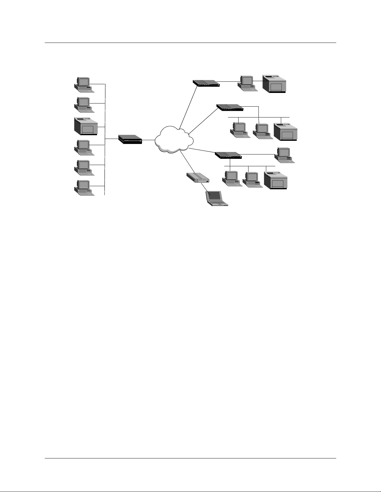
Figure 2-2. Using the MAX as a telecommuting hub
Configuration Concepts and Profiles
Overview of MAX configuration
Corporate
headquarters
Frame Relay line
WAN
MAX
Analog line
LAN
Pipeline 25
Switched 56
ISDN BRI line
Modem
Pipeline 400
LAN
Pipeline 50
LAN
T raveling user
Telecommuter
Remote office
Customer site
In this sample network, a telecommuter in a home office uses a Pipelin e 25 and Frame Relay to
log in to the corporate LAN. Users on a remote office LAN access the backbone through a
Pipeline 400 with a Switched-56 connection. A customer can access selected corporate
network resources by means of a Pipeline 50 with an ISDN BRI connection. A mobile user
with an analog modem can dial in to the backbone, provided that the MAX has a digital
modem card installed.
Notice that each user can access the MAX through a different type of line. While one user
might access the MAX by using the switched services on an ISDN BRI or Switched-56 line,
another might require a nailed 56K Frame Relay circuit.
Overview of MAX configuration
Before you configure the MAX, you should create a network diagram. Configuration tasks
generally consist of:
• Configuring the lines, channels, and ports, and how calls are routed between them
• Configuring Wide Area Network (WAN) connections and security
• Configuring the MAX as a Frame Relay or X.25 concentrator
• Configuring routing and bridging across the WAN
• Configuring Internet services, such as multicast, OSPF, and Virtual Private Networks
(VPNs)
MAX 6000/3000 Network Configuration Guide 2-3
Page 34

Configuration Concepts and Profiles
Overview of MAX configuration
Creating a network diagram
Lucent strongly recommends that, after you have read these introductory sections, you diagram
your network and refer to the diagram while configuring the MAX unit. Creating a
comprehensive network diagram hel ps prevent problems durin g inst allatio n and co nfigurat ion,
and can help in troubleshooting any problems later.
Configuring lines, slots, and ports for WAN access
The MAX unit has four built-in T1 or E1 lines and a V.35 serial port (8 Mbps). Each T1 or E1
line has a wide variety of configuration options, including whether or not you use ISDN
signaling, the type of physical-layer framing, cable length, and telco options. The way you
configure each line affects how much bandwidth will be available and whether you can direct
outbound calls to use specific channels. The way you configure channels depends on your
connectivity needs.
Use the serial WAN port for a leased high-speed connection to a Frame Relay switch or to
another WAN router. The port itself requires little configuration. A Frame Relay or Connection
profile specifies most of the required information.
You can add expansion modules to support additional bandwidth (BRI lines), serial host por t
modules to support videoconferencing, and digital modems to support analog modem
connections over digital lines. The lines and ports on the modules (cards) have their own
configuration requirements, including the assignment of telephone numbers and information
about routing calls.
Once you enable the lines, slots, and ports for WAN access, you need to configure the way in
which outbound calls are routed to them (for dial-ou t access to the WAN) and the way in which
inbound calls are routed from them to other destinations (such as the local network).
Configuring WAN connections and security
When the MAX receives packets that require establishment of a particular WAN connection, it
automatically dials the connection. Software at both ends of the connection encapsulates each
packet before sending it out over the telephone lines. Each type of encapsulation supports its
own set of options, which can be configured on a per-connection basis to enable the MAX to
interact with a wide range of software and devices.
After a connection’s link encapsulation method has been negotiated , the MAX typically uses a
password to authenticate the call. For detailed information about authentication and
authorization, see the MAX Security Supp lement. Following are some of the connection
security features the MAX supports:
Feature Description
Authentication
protocols
Callback security You can have the MAX call back any user dialing in to it, thus
2-4 MAX 6000/3000 Network Configuration Guide
For PPP connections, the MAX supports both Password
Authentication Protocol (PAP) and Challenge-Handshake
Authentication Protocol (CHAP). CHAP is more secure than PAP, and
is preferred if both sides of the connection support it.
ensuring that the connection is made with a known location.
Page 35

Configuration Concepts and Profiles
Overview of MAX configuration
Feature Description
Caller-ID and
called-number
authentication
Authentication
servers
Security card
authentication
Terminal server After a dial-in user has met the initial connection-security criteria, you
Filters and firewalls Packet-level security mechanisms can provide a very high level of
You can restrict who can access the MAX, by verifying the caller-ID
before answering the call. You can also use the called number to
authenticate and direct the call.
You can off load the authentication responsibility to a RADIUS o r
TACACS server on the local network.
The MAX supports hand-held personal security cards, such as those
provided by Enigma Logic and Security Dynamics. These cards
provide users with a password that changes frequently, usually many
times a day. Support for dynamic passwords requires the use of a
RADIUS server that has access to an authentication server, such as an
Enigma Logic SafeWord AS or Security Dynamics ACE
authentication server.
can demand another password for access to the MAX terminal
services. Within the terminal server, you can restrict commands that
are accessible to users, or you can prevent them from executing any
command other than Telnet.
network security.
Concentrating Frame Relay connections
The MAX provides extensive support for Frame Relay. Using a T1 or E1 line or serial WAN
port for a nailed connection to a switch, it can function as a Network to Network Interface
(NNI) switch, a Data Circuit-terminating Equipment (DCE) unit responding to users, or as a
Data Terminal Equipment (DTE) unit requesting services from a switch.
Enabling X.25 terminal connections
X.25 is a precursor to Frame Relay and is generally considered less efficient. However, many
sites use it to transmit information between users across the WAN. It accommodates both
high-volume data transfers and interactive use of host machines. The MAX can have one
physical connection to an X.25 DCE unit at the other end of a T1, E1, or BRI line. To support
interactive use, the connection must be nailed.
Configuring routing and bridging across the WAN
Routing and bridging configurations enable the MAX to forward packets between the local
network and the WAN and also between WAN connections.
Enabling protocol-independent packet bridging
The MAX can operate as a link-level bridge, forwarding packets from the Ethernet network to
a WAN connection (and vice versa) on the basis of the destination hardware address in each
packet. Unlike a router, a bridge does not examine packets at the network layer. It simply
forwards packets to another network segment if the address does not reside on the local
segment.
MAX 6000/3000 Network Configuration Guide 2-5
Page 36

Configuration Concepts and Profiles
Overview of MAX configuration
Using IPX routing (NetWare 3.11 or later)
The MAX can operate as an IPX router, linking remote NetWare LANs with the local NetWare
LAN on the Ethernet netw ork. IPX routing has its own set of concerns related to the
client-server model and user logins. For example, users should remain logged in for some
period even if the connection has been brought down to save connection costs.
IP routing
IP routing is the most widespread use of the MAX, and it has a wide variety of configurable
options. IP routing is the required protocol for Internet-related services such as IP multicast
support, OSPF, and cross-Internet tunneling for Virtual Private Networks (VPNs). Most sites
create static IP routes to enable the MAX to reliably bring up a connection to certain
destinations or to change global metrics or preferences settings.
Configuring Internet services
All Internet services and routing methods require that the MAX function as an IP router, so an
IP routing configuration is a necessary precondition.
Multicast
The Multicast Backbone (MBONE) is a virtual network layered on top of the Internet to
support IP multicast routing across point-to-poin t lin ks . It is often used for transmitting audio
and video on the Internet in real time, because multicasting is a much cheaper and faster way to
communicate the same information to multiple hosts.
OSPF routing
Open Shortest Path First (OSPF) is the next generation Internet routing protocol. The MAX
can be configured to communicate with other OSPF routers within an Autonomous System
(AS). To enable this routing function, you must configure the OSPF options on the Eth ernet
interface and for each WAN connection that supports remote OSPF routers.
OSPF can import routes from RIP as well. Y o u can control how these imported external routes
are handled by adjusting systemwide routing options such as route preferences and ASE-type
metrics.
Virtual Private Networks
Many sites use the Internet to connect corporate sites or to enable mobile nodes to log in to a
corporate backbone. Such Virtual Private Networks (VPNs) use cross-Internet tunneling to
maintain security or to enable the Internet to transport packets that it would otherwise drop,
such as IPX packets. To implement VPNs, the MAX supports both Ascend Tunnel
Management Protocol (ATMP), which is a Lucent proprietary tunneling mechanism, and
Point-to-Point Tunneling Protocol (PPTP).
ATMP enables the MAX unit to create and tear down a tunnel to another unit. In effect, the
tunnel collapses the Internet cloud and provides direct access to a home network. Packets
received through the tunnel must be routed, so ATMP currently applies only to IP or IPX
networks.
2-6 MAX 6000/3000 Network Configuration Guide
Page 37

A PPTP session occurs between the MAX and a Windows NT server over a special TCP
control channel. Either end might initiate a PPTP session and open the TCP control channel.
Note that opening a PP TP session does not mean that a call is active. It simply means that a call
can be placed and received.
MAX profiles
A profile is a group of related parameters and always appears as a menu item in the VT100
interface. Many profiles contain subprofiles which are, essentially, submenus within a profile.
Whether a profile is called a profile or a subprofile depend s on th e contex t because almo st an y
profile can be considered a subprofile in some sense.
To access a profile, you must have the necessary privileges. To activate a profile so that its
settings take effect, you need further privileges.
Obtaining privileges to use the profiles
As explained in the Installation and Basic Configuration Guide, privileges are often required
for changing settings in MAX profiles. To activate a profile, for example, you need full
privileges. Unless you have a personal profile that grants full privileges, you must activate the
Full Access profile. Proceed as follows:
1 At the Main Edit Menu, press Ctrl-D.
The Main Edit Menu’s DO menu appears.
2 Select P (Password).
3 Press Enter or the Right Arrow key.
The Security menu appears, displaying a list of Security profiles.
4 Select Full Access.
5 Press Enter or the Right Arrow key.
A password-entry field appears.
6 Enter your password within the brackets.
7 Press Enter or the Right Arrow key.
If your password is accepted, you have Full Access privileges.
8 Press Enter.
The Main Edit Menu reappears.
Configuration Concepts and Profiles
MAX profiles
Activating a profile
When you have full privileges, you can make a profile active. Proceed as follows:
1 Open the profile that you want to make current.
2 Press Ctrl-D.
The profile’s DO menu appears.
3 Select L (Load).
The Load profile....? menu appears.
4 Select 1 to load the profile.
Profile loaded as current profile appears.
MAX 6000/3000 Network Configuration Guide 2-7
Page 38

Configuration Concepts and Profiles
MAX profiles
The newly activated profile reappears.
Saving a profile
When you exit a profile after changing any of the settings, you are prompted to accept or
discard the changes. You must select the accept option if you want to retain the new settings.
For example, to create a new Line Config profile, complete each of the following steps:
1 Open Net/T1 > Line Config and select an unconfigured profile.
2 Press the Right Arrow key and enter a descriptive name as the setting for the Name
parameter.
3 Continue setting the parameters that are relevant for your environment.
4 When you have set all the relevant parameters, press the Back Arrow key to exit the
profile. The following message appears:
EXIT?
0=ESC (Don’t exit)
1=Exit and discard
2=Exit and accept
5 Select the number that reflects the action you want to take.
Using RADIUS
You can use RADIUS to externally authenticate connections answered by the MAX unit.
External authentication centralizes the management of WAN connections, and concentrates
user profiles into a single text file. The use of RADIUS also enables token-card authentication
for secure networks, or authentication based on a UNIX password database. For details about
obtaining and installing the Ascend RADIUS daemon and dictionary, and for a sample users
file, see the TAOS Radius Guide and Reference.
RADIUS profiles are composed of three parts:
User-Name Check-Items
Reply-Items
The User-Name must be left justified. It is typically the name of the caller (or calling device),
but it may also be a phone number (for CLID or DNIS authentication), a special string
indicating a pseudo-user profile, or the string
details about pseudo-user profiles, see the TAOS Radius Guide and Reference.
Check-Items must be on the same line as the User-Name, and must be separated by white
space (space or tab) from the User-Name. Check-Items includes zero or more attribute-value
pairs that must match the attributes that are present in the Access-Request for the user to be
authenticated. Check-Items typically include the password for the entry.
Reply-Items must be indented and separated from the User-Name and Check-Items by a
newline. (If a Reply-Item is not indented, it is interpreted as the User-Name of a new entry.)
Reply-Items includes zero or more attribute-value pairs that are returned in Access-Accept
messages to authorize services for the user.
DEFAULT
(for the default user profile). For
2-8 MAX 6000/3000 Network Configuration Guide
Page 39

Using session accounting
Both RADIUS and TACACS+ enable administrators to keep track of connection statistics,
usually for billing purposes. For details on session accounting see the T AOS Radius Guide and
Reference.
Where to go next
When you have planned your network, you are ready to configure the MAX. The flexibility of
the MAX and its ever-increasing number of configurations means there is no set order for
configuration. You can perform conf igur ation tasks in any order you want. Table 2-1 show s
where to look for the information you need.
Table 2-1. Where to go next
To do this: Go to this chapter or document:
Configure slots, lines, and ports Chapter 3, “Configuring WAN Access”
Configure WAN connections Chapter 4, “Configuring Individual WAN Connections”
Configuration Concepts and Profiles
Where to go next
Set up Frame Relay Chapter 5, “Configuring Frame Relay”
Set up X.25 Chapter 6, “Configuring X.25”
Set up packet bridging Chapter 13, “Configuring Packet Bridging”
Set up IPX ro uting Chapter 11, “Configuring IPX Routing”
Set up IP routing Chapter 7, “Configuring IP Routing”
Set up OSPF routing Chapter 8, “Configuring OSPF Routing”
Set up multicast forwarding Chapter 9, “Setting Up IP Multicast Forwarding”
Set up Virtual Private Networks Chapter 10, “Setting Up Virtual Private Networks”
Work with status windows MAX Reference
Write configuration scripts MAX Administration Guide
Set up security MAX Security Supplement
Set up RADIUS TAOS RADIUS Guide and Reference
MAX 6000/3000 Network Configuration Guide 2-9
Page 40

Page 41

Configuring WAN Access
Introduction to WAN configuration. . . . . . . . . . . . . . . . . . . . . . . . . . . . . . . . . . . . . . . . 3-2
Configuring T1 lines . . . . . . . . . . . . . . . . . . . . . . . . . . . . . . . . . . . . . . . . . . . . . . . . . . . 3-7
Configuring E1 lines . . . . . . . . . . . . . . . . . . . . . . . . . . . . . . . . . . . . . . . . . . . . . . . . . . 3-19
Configuring the serial WAN port. . . . . . . . . . . . . . . . . . . . . . . . . . . . . . . . . . . . . . . . . 3-28
Configuring digital modems . . . . . . . . . . . . . . . . . . . . . . . . . . . . . . . . . . . . . . . . . . . . 3-29
Configuring V.110 modems . . . . . . . . . . . . . . . . . . . . . . . . . . . . . . . . . . . . . . . . . . . . . 3-32
Configuring Personal Handyphone System (PHS) . . . . . . . . . . . . . . . . . . . . . . . . . . . 3-33
Configuring ISDN BRI network cards. . . . . . . . . . . . . . . . . . . . . . . . . . . . . . . . . . . . . 3-33
Configuring Host/BRI lines. . . . . . . . . . . . . . . . . . . . . . . . . . . . . . . . . . . . . . . . . . . . . 3-39
Configuring IDSL connections . . . . . . . . . . . . . . . . . . . . . . . . . . . . . . . . . . . . . . . . . . 3-42
Configuring Host/AIM6 and Host/Dual ports. . . . . . . . . . . . . . . . . . . . . . . . . . . . . . . 3-47
3
Configuring call routing. . . . . . . . . . . . . . . . . . . . . . . . . . . . . . . . . . . . . . . . . . . . . . . . 3-58
A MAX unit supports up to four T1- or E1-line connections. It also has a serial WAN port,
which typically connects to a Frame Relay switch, and six slots for expan sion cards. Ex pansion
cards can provide other types of WAN connections. Digital-modem cards and V.110-modem
cards provide communications with analog modem users and V.110 Terminal Adapter users,
respectively. In Japan, MAX units support Personal Handyphone System (PHS). You can
install and configure an ISDN BRI card if yo ur conn ections do not warrant the expense o f a T1
or E1 line. With the Host/BRI module, the unit emulates a telco switch providing ISDN BRI
lines to local hosts. The BRI/LT card supports Lucent’s ISDN Digital Subscriber Line (IDSL)
standard for voice and data transmissions. To provide the bandwidth needed for video
teleconferencing, Host/AIM6 and Host/Dual cards support two types of inverse multiplexing:
Bandwidth ON Demand Interoperability Group (BONDING) and Ascend Inverse
Multiplexing (AIM). If your unit connects only to ISDN lines and supports o nly
digital-modem cards, call routing is preconfigured . You must configure it, howe ver, if you
have a mixtu re of cards or if the WAN lines do not support ISDN signaling.
MAX 6000/3000 Network Configuration Guide 3-1
Page 42
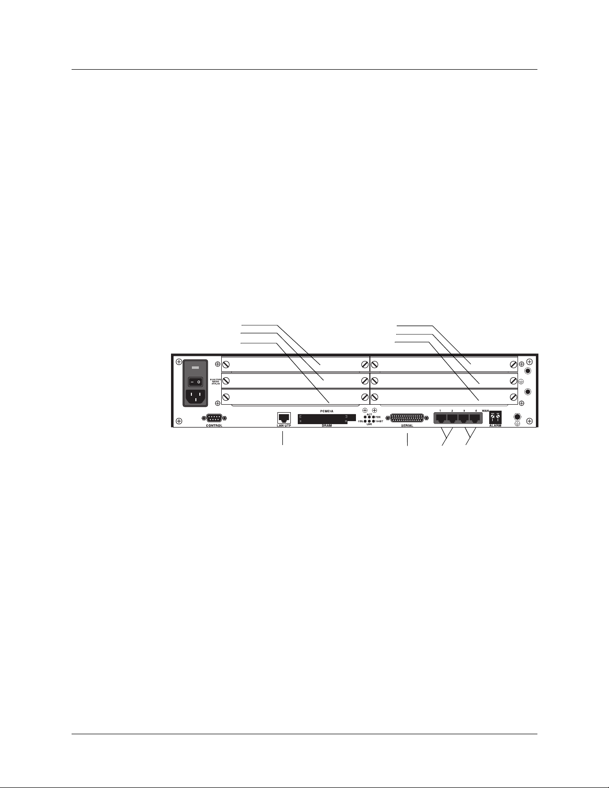
Configuring WAN Access
Introduction to WAN configuration
Introduction to WAN configuration
To configure a MAX unit, you set parameters in the VT100 menus. (For a description of
navigating the interface, see the Installation and Basic Configuration Guide for your MAX.)
Many of the menus and submenus include profiles, which are groups of related parameters. To
begin setting the parameters, you must understand how the VT100 menus relate to slots and
ports. You must also understand telephone number assignments and how a MAX unit routes
inbound and outbound calls.
How the VT100 menus relate to slots and ports on the MAX 6000
The menus in the VT100 interface are numbered to correspond to slots in the MAX 600 0 unit.
A slot can be an actual expansion slot or virtual slot on the unit’s motherboar d. Virtual slots
include the System slot, two T1 or E1 slots, the Ethernet slot, the Etherdata slot, and the Serial
WAN slot.
Figure 3-1. Slot and port numbering in the MAX 6000
System slot
Slot #5
Slot #4
Slot #3
Slot #9
Slot #8
Slot #7
Slot #6
Slot B
Slot #1
Slot #2
The system itself is assigned slot number 0 (menu 00-000). The System menu contains the
following profiles and submenus, which are all related to systemwide configuratio n,
maintenance, and security:
00-000 System
00-100 Sys Config
00-200 Sys Diag
00-300 Security
00-400 Feature Codes
00-500 Destinations
00-600 Dial Plan
00-700 Answer Plan
T1 or E1 slots
The built-in T1 or E1 connections are slot 1 and slot 2 (menus 10-000 and 20-000,
respectively). Each of these slots accommodates two T1 or E1 lines. The menus for
configuring and testing the lines are organized as follows:
3-2 MAX 6000/3000 Network Configuration Guide
Page 43

10-000 Net/T1 or Net/E1
10-100 Line Config
10-200 Line Diag
20-000 Net/T1 or Net/E1
20-100 Line Config
20-200 Line Diag
Expansion slots
The six expansion slots are slots 3–8 (menus 30-000 through 80-000), numbered as shown in
Figure 3-1. (Before installing an expansion card, be sure to read any instructions that might be
packaged with the card.)
Ethernet and WAN slots
Slot 9 is the Ethernet slot (menu 90-000). The Ethernet menu contains submenus and profiles
related to the local network, routing and bridging, and WAN connectio ns. Slot A, Etherdata
(menu A0-000), is a virtual slot that provides support for 32 Ethernet sessions (to supplement
those supported by the Ethernet card). The serial WAN port is slot B (menu B0-000)
Note: There are no parameters associated with the Etherdata card. T here is no submenu und er
Etherdata on the Main menu. The Ethernet card and Etherdata card are the same type of card.
The Ethernet card allows 64 simultaneous Ethernet sessions. You configure the Ethernet
interface by means of parameters in Ethernet submenus. Each Etherdata card allows an
additional 32 Ethernet sessions.
Configuring WAN Access
Introduction to WAN configuration
How the VT100 menus relate to slots and ports on the MAX 3000
Depending on the model, a MAX 3000 unit has six BRI ports, two T1 or E1 ports, a T1 or E1
drop and insert port, and a serial port for WAN access. It also has two expansion slots. For the
purpose of organizing the menus in the VT100 interface, ev ery po rt o n the u nit is as signed to a
slot. Except for two expansion sots, the slots are virtual. That is, they exist only for the sake of
organizing the menus to correspond to the physical ports.
Figure 3-2. Slot and port nu mbering in the MAX 3000 T1
Slot #2
Slot #4
Figure 3-2 shows how ports are assigned to s lots on a MAX 3000. No t shown are slots 0 and 5,
which are exceptions in that they do not correspond to any physical port.
Slot #3
Slot #1
Slot #6
MAX 6000/3000 Network Configuration Guide 3-3
Page 44

Configuring WAN Access
Introduction to WAN configuration
System slot
The system itself is assigned to slot 0 (menu 00-000). The System menu contains the following
profiles and submenus, which are all related to systemwide configuration and maintenance:
00-000 System
00-100 Sys Config
00-200 Sys Diag
00-300 Security
00-400 Feature Codes
00-500 Destinations
00-600 Dial Plan
T1 or E1 slot
The physical built-in T1 or E1 line interfaces are assigned to slot 1 (menu 10-000). The T1 or
E1 slot includes two ports, plus a third port reserved for a drop and insert (D&I) line. The
menus for configuring and testing the lines connected to the ports are organized as follows:
10-000 Net/T1 or Net/E1
10-100 Line Config
10-200 Line Diag
Expansion slots
Ethernet slot
Etherdata slot
Serial WAN slot
The two expansion slots are slots 2 and 3 (menus 20-000 and 30-000). The corresponding
physical expansion slots are numbered 2 and 3, from left to right.
The Ethernet port is slot 4 (menu 40-000). The Ethernet menu contains submenus and profiles
related to the local network, routing and bridging, and WAN conn ections.
The Etherdata slot is slot 5 (menu 50-000), representing Ether Data HDLC channels. The
Etherdata card gives the MAX 32 extra use r Ether net ses sions. Without the Etherdata card, the
MAX supports only 64 simultaneous Ethernet sessions. With two Etherdata cards, the unit can
support 128. Etherdata data cards are no longer available as expansion cards. MAX units
configured for T1 units have 1 virtual Etherdata card built onto the motherboard, and MAX
units configured for E1 units have 2 virtual Etherdata cards built onto the motherboard.
The serial port is slot 6 (menu 60 -00 0). It is use d fo r the s erial WAN connection or a nailed-up
T1/E1 connections.
V.90 S56 III modem slot
The on-board modems are assigned to slot 7 (menu 70-000).
3-4 MAX 6000/3000 Network Configuration Guide
Page 45

Assigning telephone numbers
A MAX unit receives calls on telephone numbers assigned to its T1 or E1 and (if applicable)
Net/BRI channels. Each number has a limit of 24 characters, which can include the following:
1234567890()[]!z-*#|
T o ass ign the numb ers, yo u must und erstan d add-o n numb ers, hu nt grou ps, and Servi ce Profi le
Identifiers (SPIDs).
Add-on numbers
You build multichannel calls (MP, MP+, AIM, or BONDING) by specifying add-on numbers.
A multichannel call begins as a single-channel connection to one telephone number. The
calling unit can then request and store additional numbers that it dials to connect additional
channels. To add channels to the call, the calling unit must integrate the add-on numbers with
the number it dialed initially. The parameters you set to specify add-on numbers depend on the
type of line you are configuring. For a T1 or E1 line, set the Ch N# parameters. For a BRI line,
set the Pri Num parameter. For some BRI lines, (that is, for multipoint mode) you must also set
the Sec Num parameter.
Configuring WAN Access
Introduction to WAN configuration
The group of channels used for a multichannel call is called a bundle. A 10-chan nel bun dle, in
which each channel is 64Kbps, provides a 640 Kbps connection. Typically, the telephone
numbers assigned to a bundle share a group of leading digits. Enter only the unique digits
identifying each number, as follows:
• If the add-on number in the called unit is shorter than the telephone number dialed by the
calling unit, the MAX unit replaces only the rightmost digits. For example, suppose you
dial 777-3330 to reach channel 1 of line 1, and dial 777-3331 through 777-3348 to reach
other channels (on the same line or a different line). In this case, set Ch1# to 30, and set
the Ch N# parameter for each of the other channels to 31, 32, and so forth.
• If the add-on number is longer than the number dialed, the unit discards the extra digits.
For example:
– Ch1#=510-655-1212
– Dial#=655-1212
– Derived number for channel 1=655-1212
• If there is no add-on number, the derived number equals the dialed number. For example:
– Ch1#=(null)
– Dial#=555-1213
– Derived number for channel 1=555-1213
Note: The most common reason multichannel calls fail to connect beyond the initial
connection is that the answering unit sends the calling unit add-on numbers it cannot use to dial
the other channels. For example, AIM and BONDING call bund les shou ld n ot span d ial plans.
If you are receiving AIM or BONDING calls and have multiple dial plans, set up each dial
plan as a separate trunk group. This also prevents MP and MP+ call bundles from spanning
dial plans. If you have, for example, two PRI lines fr om different service providers, you might
set the ChN Trnk Grp parameters for the first line to 9 and for the second line to 8. For more
information about trunk groups, see “Enabling trunk groups” on page 3-68.
MAX 6000/3000 Network Configuration Guide 3-5
Page 46

Configuring WAN Access
Introduction to WAN configuration
Hunt groups
A hunt group is a group of channels to which the carrier assigns a single telephone number.
When a call comes in on that number, the Central Office switch delivers the call to the first
available channel. Because channels in a hunt group share a common telephone number, the
add-on numbers in the profile are the same.
Note: If all of a line’s channels have the same add-on number, you can leave the telephone
number assignment blank.
SPIDS (for Net/BRI lines)
The Service Profile Identifiers (SPIDs) assigned to a BRI line operating in multipoint mode are
numbers used at the Central Office switch to identify services provisioned for your ISDN line.
Your carrier bases the SPIDs on the telephone numbers assigned to your BRI lines, and tells
you the SPIDs when it installs the lines.
Most, but not all telephone companies include a suffix on their SPIDs. When receiving SPIDs
from your telephone company, ask whether or not suffixes are included. The following SPID
formats have been agreed upon by most telephone companies.
For an AT&T switch in multipoint mode , SPI Ds have one of the following formats:
01
nnnnnnn
01
nnnnnnn
0
00
In the AT&T SPID formats, nnnnnnn is the 7 digit telephone number (not including the area
code). For example, if the telephone number is 555-1212, the SPID is 0155512120 or
01555121200. For a Northern Telecom switch, SPIDs have one of the following formats:
aaannnnnnnSS
aaannnnnnnSS
00
In the Northern Telecom SPID formats, aaannnnnnn is the 10-digit telephone number
(including the area code). SS is an optional suffix. If included, the suffix is a 1 or 2 digit
number differentiating the channels. For example, if the telephone numbers are 212-555-1212
and 212-555-1213, the SPIDs might be:
21255512121
21255512132
or:
212555121201
212555121302
In some cases, the suffix is followed by 00 (for example, 21255512130200).
How a MAX unit routes inbound and outbound calls
When a MAX unit receives a call on one of its WAN interfaces, it routes that call internally to
one of its slots or ports. When a digital modem, AIM port, or a host on the local Ethernet port
originates a dial-out connection, the unit routes that call internally to an available WAN
channel to place the call. The channel configuration of a WAN line determines how the
3-6 MAX 6000/3000 Network Configuration Guide
Page 47

channel routes inbound calls and places outbound calls. For details, see “Configuring call
routing” on page 3-58.
Configuring T1 lines
A MAX 6000 unit that supports T1 lines has two T1 slots, each of which supports two T1
lines. Configure a Line Config profile for each of the two slots. You can also configure
additional Line Config profiles, but only one can be active for a given slot at a given time. For
a MAX 3000 unit, only one Line Config profile can be active at a given time. In addition to a
few general parameters, a Line Config profile contains a subprofile for each line connected to
the slot. Each subprofile provides parameters for configuring the line’s connection to the
Central Office switch. You can customize the settings for monitoring line quality and
supporting PBX connections. Other parameters apply to carrier-specific services. Also, you
can enable the MAXDAX feature, which routes incoming calls from inbound T1 or PRI lines
to specific outgoing channels on the same or different T1 (inband) or PRI lines. Each of the
two subprofiles also includes parameters for configuring individual channels within the line.
Setting the general parameters
Configuring WAN Access
Configuring T1 lines
To create a new T1-line configuration, open the Net/T1 > Line Config menu and display an
available profile:
Net/T1
Line Config
Line Config profile
Name=
1st Line=
2nd Line=
Line 1...
Line 2...
Set the Name parameter to assign a descriptive name to the configuration. (You can configure
multiple profiles for the same slot and activate a profile when it is needed. To activate a profile,
see “Activating a profile” on page 2-7.)
You can set 1st Line and 2nd Line to Trunk (indicating a standard T1 interface with signaling
information), Quiesced, or Disabled. For the second line connected to a MAX 6000 E1 slot,
you can also specify D&I (Drop-and-Insert) service. (A MAX 3000 unit has no D&I setting for
the 2nd Line parameter. Instead, line 3 can be used for D&I only.) Drop-and-Insert on the
second line specifies that some of the first line’s channels transparently move to the second
line. A device such as a PBX connected to the second line is not aware that the channels
actually pass through the MAX unit. For more information about each parameter , see the MAX
Reference.
MAX 6000/3000 Network Configuration Guide 3-7
Page 48

Configuring WAN Access
Configuring T1 lines
Connecting to the Central Office switch
T o conf igure a line’s connection to the Central Office switch, open the Net/T1 > Line Config >
Line Config profile > Line N subprofile for the line and set the following parameters:
Parameter Specifies
Sig Mode The signaling type for the line.
NFAS ID Num An interface ID number for a line using Non-Facility Associated
Signaling (NFAS). Each NFAS line must have a different ID number.
Rob Ctl The robbed-bit call-control mechanism that the MAX unit uses for
inband signaling.
Switch Type Type of switch (carrier specific) providing the ISDN service.
Framing Mode Physical-layer frame format of the T1 line.
Front End Type of interface used on the T1/PRI port. Select CSU (the default) if
you plan to use the MAX unit’s internal CSU, or select DSX if you
plan to connect the port to other equipment that provides the interface
to the WAN, (an external CSU, for example), and disable the internal
CSU.
Encoding Type of encoding that the line uses at the physical-link layer.
Length The distance between the CSU and the MAX unit. Applies to a MAX
using external CSUs only.
Buildout Amount of attenuation, in decibels, to apply to the internal CSU.
Consider specifying a value if the MAX is using an internal CSU too
near a repeater. For additional information, consult your carrier.
Clock Source That the line can (Yes) or cannot (No) be used as the clock source for
timing synchronous transmission s between the sending and the
receiving device. A MAX unit only has one clock source. The firs t line
that comes up is the clock source for all the lines. If you set this
parameter to No, the MAX uses its internal clock.
Collect DNIS/ANI That DNIS and CLID information from the switch are (Yes) or are not
(No) available for authentication and accounting. Applies to inband
signaling only. With the Yes setting, the Digital Signal Processor
(DSP) decodes the calling and called DTMF digits.
Send Disc Number of seconds the MAX unit waits, from the time the call is
presented, before clearing the call.
For detailed information about each parameter, see the MAX Reference.
Signaling mod e
You must configure the signaling type (Sig Mode) for each T1 line.
If you set Sig Mode to ISDN_NFAS, you can also establish an interface ID or NFAS ID
number for this type of signaling. You must specify a different interface ID for each NFAS
line.
3-8 MAX 6000/3000 Network Configuration Guide
Page 49

If you set Sig Mode to Inband signaling (also called robbed-bit signaling), you must set the
Rob Ctl parameter to specify a call-control mechanism. For additional information, consult
your carrier.
Switch-specific settings
Set the Switch Type parameter to specify the network switch providing ISDN service on the
T1/PRI line. The carrier supplies the setting. You must also specify the physical layer frame
format for the T1 line by setting the Framing Mode parameter.
Front-end settings
The Front End parameter specifies the type of Channel Service Unit (CSU) used for the T1
line. Your carrier can assist you in setting the Encoding parameter. This parameter specifies the
Layer-1 line encoding used for physical links, which affects the way the digital signals on the
line represent data. Set the Length parameter if you are using an external CSU. If using the
internal CSU, ask your carrier about a value, if any, for the Buildout parameter.
Monitoring line quality
Configuring WAN Access
Configuring T1 lines
The telephone company uses a Facilities Data Link (FDL) protocol to monitor the quality and
performance of T1 lines. In a line’s subprofile, set the FDL parameter to specify the protocol.
If you are not sure which FDL protocol to specify, your telephone carrier can tell you.
Supporting PBX connections
In a MAX 3000 unit’s T1 slot, or in either T1 slot of a MAX 6000, you can connect line 2 to a
PBX. The unit can act as a switch, moving an incoming call from line 1 to line 2. You can
assign the PBX a number for dialing out through the MAX unit. If the second line’s signaling
mode is PBX T1, you can route calls to the PBX. For all calls received by the PBX, you can
specify a sample count to provide accurate tone detection and decoding. To support PBX
connections, you set the following parameters in the Net/T1 > Line Config > Line Config
profile > Line N subprofile:
Parameter Specifies
PBX Type The type of signaling to be used with the PBX on line 2.
Delete Digits The number of digits to be deleted from the beginning of the dialed
number to allow a PBX on line 2 can dial out through the MAX unit.
Add Number A series of digits to be added to the beginning of the dial-out telephone
number after the digits specified by Delete Digits have been removed.
Ans # A telephone number to be used for routing calls received on the first T1
line to the device terminating the second T1 line when the second line’s
signaling mode is PBX T1. The answer number is one of the unit’s
telephone numbers. (For more information, see “Configuring call
routing” on page 3-58.”)
Ans Service A data service (voice, for example). Any call that uses the specified data
service will be routed to line 2,. This parameter can be used as an
alternative to Ans # when the second line’s signaling mode is PBX T1.
(For more information, see “Configuring call routing” on page 3-58.)
MAX 6000/3000 Network Configuration Guide 3-9
Page 50

Configuring WAN Access
Configuring T1 lines
Input Sample
Count
For detailed information about each parameter, see the MAX Reference.
Allows the PRI-T1 conversion process to use number (one or two) of sets
of Goertzel samples the PRI-T1 conversion process is to use for DTMF
tone detection. By default, the MAX uses only one sample to decode
signals from robbed-bit PBXs, because some PBX devices have a tone
duration of less than 50ms, which does not provide enough time to
compute two sets of Goertzel samples. The PRI-T1 convers ion proces s is
more accurate when the MAX can use two samples. Using two samples is
recommended when the tone duration is longer than 70ms.
Configuring carrier-specific services
To enable the MAX to communicate with your carrier’s switch, and vice versa, obtain values
for the Call-by-Call, T1-PRI:PRI # Type, and T1-PRI:NumPlanID parameters from your
service provider . The v alue specified for the Call-by-Call parameter sets th e signaling value for
routing calls. The T1-PRI:PRI # Type and T1-PRI:NumPlanID parameters specify values that
the MAX unit applies to outbound calls on PRI lines so that the switch can properly interpret
the telephone number dialed.
To configure carrier-specific services, open the Net/T1 > Line Config profile > Line N
subprofile for the line you are configuring and set the following parameters:
Parameter Specifies
Call-by-Call Service provider’s call-by-call signaling value for routing calls from a
local device to the carrier’s network through the MAX unit.
T1-PRI:PRI # Type TypeOfNumber field in the called party’s information element.
T1-PRI:NumPlanID NumberPlanID field in the called party’s information element.
For detailed information about each parameter, see the MAX Reference.
Using MAXDAX
MAXDAX enables you to route incoming calls from T1 or PRI lines to specific outgoing
channels on the same or different T1 or PRI lines. To implement MAXDAX, you must set
parameters in the Net2Net Incoming Calls and Net2Net ChanGroup ID profiles. In the
Net2Net Incoming Calls profile, you define parameters used in configuring channels on which
the MAX unit receives incoming calls. In the Net2Net ChanGroup ID profile, you define
parameters used in configuring channels for outbound calls.
For complete information about MAXDAX, see “Configuring MAXDAX” on page 3-73. Or,
for detailed information about each parameter, see the MAX Reference.
Following are the parameters you set in the Net/T1 > Line Config profile > Line N > Net2Net
Incoming Calls profile:
Parameter Specifies
3-10 MAX 6000/3000 Network Configuration Guide
Page 51

Ch N A switched connection for MAXDAX. That is, you must set Ch N
Ch N Dest ChanGroup The channel group number to which the MAX unit directs
Ch N Dial Plan # A Dial Plan profile for the calls received by this channel.
Ch N #DialPlanSelDigits The number of leading digits the unit strips from the called
In the Net/T1 > Line Config > Line Config profile > Line N > Net2Net ChanGroup ID profile,
you set the following parameters:
Parameter Specifies
Ch N A switched connection for MAXDAX. That is, you must set Ch N
Ch N ChanGroup The group to which the channel is assigned.
Configuring channels
Configuring WAN Access
Configuring T1 lines
to Switched.
outbound calls.
number.
to Switched.
Each built-in T1 line provides 24 channels, each of which can support one single-channel
connection. Depending on the signaling mode used on the line, all 24 chann els are available for
user data, or 23 channels are available for data and the 24th channel is reserved for signaling.
Each channel can be either switched or nailed. You can assign a switched channel to a slot/port
combination. To make a nailed channel available, you assign the channel to a group, and then
assign that group number to the Connections or call profile.
Following are the relevant parameters, which are in each Net/T1 > Line Config > Line Config
profile > Line N subprofile. (In the parameter names, N represents a number distinguishing an
individual parameter from other parameters of the same type.)
Parameter Specifies
Ch N Type of connection that supports the channel.
Ch N # Any add-on telephone number as sociated with a switched channel
only .
Ch N Slot A slot number for switched calls to be routed to and from this
channel.
Ch N Prt/Grp For switched calls, a port number to be used with the Ch N Slot
parameter for call routing purposes. For nailed channels, the
group number of the nailed channels used for the connection.
Ch N Trnk/Grp Trunk group to which a nailed channel is assigned to make it
available for outbound calls.
Hunt-N # A hunt-group number (a telephone number) associated with the
T1 line in a specific Line N profile. Your carrier assigns the hunt-
group number.
For detailed information about each parameter, see the MAX Reference.
MAX 6000/3000 Network Configuration Guide 3-11
Page 52

Configuring WAN Access
Configuring T1 lines
The Ch N parameters are repeated for each channel in the line. (There are 23 channels if you
use PRI signaling and 24 channels if you use robbed-bit signaling.)
The Ch N # parameter is an add-on number associated with each switched channel (as
described in “Add-on numbers” on page 3-5).
Associating a c hannel with a slot/ port in the MAX unit
With the Ch N Slot and Ch N Prt/Grp parameters, you can assign a switched channel to a slot or
slot/port combination for a digital modem, AIM port, or Ethernet network. This configuration
affects both inbound call routing and outbound calls. In effect, it reserves the channel for calls
to and from the specified slot or port. (For details, see “Configuring call routing” on
page 3-58.)
Assigning nailed channels to groups
If the channel is nailed, Ch N Prt/Grp specifies a group number to which the channel belongs.
To make use of this nailed connection, a Connection or call profile references the group
number. (You use a call profile to configure a Host interface. A call profile is analogous to a
Connection profile. A call profile is associated with a video-conferencing host. There can be
only one video call up at one time, so there is only one active call profile. The call profiles are
located in Host/Dual (or Host/AIM6) > PortN menu > Directory > any call profile.)
Assigning channels to tr unk groups
You can assign trunk-group numbers 4–9 to channels to make them available for outbound
calls. (For details, see “Routing outbound calls” on page 3-68.)
Assigning channels to hunt groups
If your carrier provides hunt-group server, you must set the Hunt-N# parameter to specify the
hunt group number that the carrier has configured on the CO switch. When dial-in clients
require additional bandwidth, the MAX forwards the hunt group number to the client. This
process is built into the bandwidth allocation protocols.
You can assign a hunt-group number (a telephone number) associated with the T1 line in a
specific Line N profile. Assign this value to the Hunt-N # parameter.
Typical T1 configurations, with examples
Typical T1-line configurations for MAX units include configurations for ISDN PRI services,
robbed-bit signaling, NFAS signaling, PRI-to-T1 conversion for a T1 PBX, and assigning
bandwidth to a nailed link.
Configuring a line for ISDN PRI service
When configuring ISDN PRI service for a MAX unit, you must configure ISDN signaling for
the line. Optionally, you can configure the unit to send either ISDN code 16 (Normal call
clearing) or code 17 (User busy) when the PRI switch servicing the unit triggers the T310
timer. Also, you can configure overlap receiving if you want the unit to obtain complete
called-number information from the network switch.
3-12 MAX 6000/3000 Network Configuration Guide
Page 53

Configuring WAN Access
Configuring T1 lines
Configuring ISDN signaling
T o conf igure a T1 line for ISDN signaling, proceed as follows:
1 Open a Net/T1 > Line Config > Line Config profile and, depending on which line you are
configuring, set the 1st Line or 2nd Line parameter to Trunk. For example:
Net/T1
Line Config
Line Config profile
Name=
1st Line=Trunk
2nd Line=Disabled
2 Open the subprofile for the line you have set to trunk service, and set the signaling mode
to ISDN. For example, if you set 1st Line to trunk, set the Sig Mode parameter in the Line
1 subprofile:
Line 1...
Sig Mode=ISDN
3 In the same subprofile, specify the framing and encoding values. For example:
Framing Mode=ESF
Encoding=B8ZS
4 Exit the Line Config profile and, exit the profile, at the exit prompt, select the exit and
accept option.
If the profile you have configured is not the active profile, activate it as described in
“Activating a profile” on page 2-7.
Configuring the Pre-T310 timer
The ISDN Pre-T310 timer feature enables users calling into a MAX unit to get better
clarification of the reasons for call disconnects during the initial setup of the call. If a call is
presented to the unit, and there is an extended period of delay while the call is being set up (for
example, heavy local Ethernet traffic is slowing down RADIUS requests or DNS lookups),
you might want your users to get a disconnect indication other than the generic Normal call
clearing.
In compliance with CCITT Specification Q.931, the unit sends a Call Proceeding message to
the network switch for every call it accepts.
The network switch sets its T310 timer as it awaits further messages from the MAX unit. The
switch tears down the call if the T310 timer expires. In this event, the switch reports ISDN
code 16 (Normal call clearing) to the calling device.
To use the MAX ISDN Pre-T310 timer, it must be set to a time period less than that of the
T310 timer on the switch. Then, after the MAX unit’s Pre-T310 timer expires but before the
switch’s T310 timer expires, the MAX sends ISDN code 17 (User busy) and clears the call.
Note: Only calls presented on T1/PRI lines support the Pre-T310 timer feature.
T o conf igure the Pre-T310 timer, proceed as follows:
1 Open a Net/T1 > Line Config > Line Config profile > Line N subprofile.
2 Set the Send Disc parameter to a value of from 0 to 60 seconds.
MAX 6000/3000 Network Configuration Guide 3-13
Page 54

Configuring WAN Access
Configuring T1 lines
The parameter must be set to a value less than that of the switch’s T310 timer value, so
that it expires before the T310 timer.
3 Open the Ethernet > Mod Config > Auth subprofile.
4 Set the Timeout Busy parameter to Yes if you would like User Bu sy sent when the Send
Disc timer expires. Set Timeout Busy to No if you would like Normal call clearing sent.
Note: The Timeout Busy parameter replaces the CLID Timeout Busy parameter.
If the profile you have configured is not the active profile, activate it as described in
“Activating a profile” on page 2-7.
Overlap receiving for the MAX unit
Overlap receiving affects the incoming-call-establishment procedure at the MAX unit.
According to ITU’s Q.931 specifications, the receiving unit can use either the en-bloc
receiving procedure or the overlap receiving procedure to handle the incoming call. If en-bloc
receiving is in use, the Setup message contains all the information required by the called user
for processing the call. But if the carrier supports overlap receiving, the received Setup
message might contain incomplete called-number information. After the network receives the
Setup Acknowledge message, it sends the remainder of the call information (if any) in one or
more Information messages. In this case, you must set the Overlap Receiv ing parameter to Yes
so that the unit can gather the complete called-number from the network switch, thus enabling
the use of features such as called-number authentication.
Example of ISDN PRI configuration
Following is an example of T1 configuration for ISDN PRI service. (Only the relevant
parameters are shown.)
Net/T1
Line Config
Line Config profile
Name=
1st Line=Trunk
2nd Line=Disabled
Line 1...
Sig Mode=ISDN
Framing Mode=D4
Encoding=AMI
Send Disc=0
Overlap Receiving=Yes
3-14 MAX 6000/3000 Network Configuration Guide
Page 55

Ethernet
Mod Config
Auth
Timeout Busy=No
Configuring robbed-bit signaling
For robbed-bit signaling, set the line you are configuring to Trunk service, and set the signaling
mode and the robbed-bit control mechanism. To configure a T1 line for robbed-bit signaling,
proceed as follows:
1 Open a Net/T1 > Line Config > Line Config profile and, depending on whi ch line you are
configuring, set the 1st Line or 2nd Line parameter to Trunk.
2 Open the subprofile for the line you have set to Trunk, and set Sig Mode to Inband.
3 In the same profile, specify the Rob Ctl parameter to specify the robbed-bit call-control
mechanism required by your carrier.
4 Set the Framing Mode parameter to specify the physical-layer frame format of the T1 line.
5 Set the Encoding parameter to specify the type of encoding that the line uses at the
physical-link layer.
6 Set the Send Disc parameter to specify the number of seconds the MAX unit waits, from
the time the call is presented, before clearing the call.
7 Set the Overlap Receiving parameter to enable the unit to gather the complete called
number from the network switch.
8 Exit the profile and, at the exit prompt, select the exit and accept option.
Configuring WAN Access
Configuring T1 lines
If the profile you have configured is not the active profile, activate it as described in
“Activating a profile” on page 2-7.
Example of robbed-bit configuration
Following is an example of T1-line configuration using all switched channels and the default
inband (robbed-bit) signaling mode. (Only relevant parameters are shown.)
NET/T1
Line Config
Using NFAS signaling
When you configure two T1 lines for NFAS signaling, they share a D channel. Configure one
line with a primary D channel and the other with a secondary D channel. The secondary D
Swtchinbnd
Name=Swtchinbnd
1st Line=Trunk
2nd Line=Disabled
Line 1...
Sig Mode=Inband
Rob Ctl=Wink-Start
Framing Mode=D4
Encoding=AMI
Send Disc=0
Overlap Receiving=Yes
MAX 6000/3000 Network Configuration Guide 3-15
Page 56

Configuring WAN Access
Configuring T1 lines
channel is used only if the primary line goes down or if it receives a signal commanding a
change to the other D channel.
Note: On a MAX 6000 unit, both lines must be connected to the same slot. Also note that if
you were to configure both slots for NFAS signaling, you would have to assign different ID
numbers to the lines in the second slot.
To configure two T1 lines for NFAS, proceed as follows:
1 Open a Net/T1 > Line Config > Line Config profile and set both lines to Trunk:
Net/T1
2 Open the Line 1 su bpr ofile an d s et the s ignalin g mod e to NFAS:
3 Keep the default NFAS ID.
4 Configure a channel as the primary NFAS D channel. For example:
5 Close the Line 1 subprofile.
6 Open the Line 2 su bpr ofile an d s et the s ignalin g mod e to NFAS:
7 Keep the default NFAS ID:
8 Configure channel 24 as the secondary NFAS D channel:
9 Exit the profile and, at the exit prompt, select the exit and accept option.
Line Config
Line Config profile
Name=
1st Line=Trunk
2nd Line=Trunk
Line 1...
Sig Mode=ISDN_NFAS
NFAS ID num=1
Ch 24=NFAS-Prime
Line 2...
Sig Mode=ISDN_NFAS
NFAS ID num=2
Ch 24=NFAS-Second
If the profile you have configured is not the active profile, activate it as described in
“Activating a profile” on page 2-7.
Example of NFAS configuration
Following is a sample configuration of two T1 lines for NFAS signaling. (Only the relevant
parameters are shown.)
NET/T1
Line Config
NFASig
Name=NFASig
1st Line=Trunk
2nd Line=Disabled
Line 1...
Sig Mode=ISDN_NFAS
Framing Mode=D4
3-16 MAX 6000/3000 Network Configuration Guide
Page 57

Configuring WAN Access
Encoding=AMI
Send Disc=0
Overlap Receiving=Yes
Enabling a robbed-bit PBX with PRI access lines (PRI-to-T1 conversion)
If your WAN uses ISDN PRI signaling on its T1 lines, a MAX unit can convert the signaling to
standard T1 for use with a PBX. With this configuration, the MAX emulates a WAN switch,
such as a Lucent 5ESS, connected to the PBX.
Note: In most cases, you cannot use this feature in combination with digital modems. Also,
the PBX must use two-state inband with DTMF signaling and must support Senderized (en
bloc) digital transmission, because the MAX unit has a preset time limit on received dialing
digits. In addition, the called number should be available from the switch. That is, you need
Dialed Number Identification Service (DNIS) or a called number information element.
On a MAX 6000 unit, T1 PBX must connect to line 2 of the unit’s second slot. That is, you
must configure line 2 in a profile in the 20-000 Net/T1 > Line Config menu. To configure the
Line Config profile that will support the PBX, set the 2nd Line parameter to Trunk. T hen, open
the subprofile for second line connected to the PBX and set the following parameters:
Configuring T1 lines
Parameter Specifies
Sig Mode The signaling mode. Select PBX T1.
Rob Ctrl The robbed-bit call-control mechanism.
T1-Pri:PRI # Type Type of calls placed by the PBX. Ask your PRI provider about
which settings are available to you.
T1-PRI:NumPlanID NumberPlanID, needed by the carrier’s switch to properly
interpret a dialed number. Ask your PRI provider about which
settings are available to you.
PBX Type The type of service the PBX expects on its T1 line. In most
installations the PBX expects voice-service calls with call
progress tones. The Data setting does not supply call progress
tones or information messages to the user.
Ans Service The type(s) of call(s) that should be converted from PRI to
robbed-bit T1 signaling. Most installations select Voice. With this
setting, the unit converts voice-service calls arriving on the PRI
line to T1 voice calls for the PBX. Data-service calls undergo
normal incoming-call routing. They are not converted and sent to
the PBX.
Note that with Ans Service set to Voice, you cannot configure the
line for both PBX T1 support and digital modem operation,
because the voice-service modem calls are diverted to the PBX
and never r each the digit al modems.
Ans # A telephone number to be used for routing incoming calls from
the first T1 line to the second T1 line. Most installations leave this
setting blank. If specified, it can be an add-on number.
Delete Digits and Add
Number
Digits to be deleted and added, respectively, to convert a number
dialed through the PBX to ISDN PRI format.
MAX 6000/3000 Network Configuration Guide 3-17
Page 58

Configuring WAN Access
Configuring T1 lines
Call by Call The ISDN PRI call-setup request to add to calls dialed out from
For more information about each parameter, see the MAX Reference.
Other considerations for PRI-to-T1 conversion
On a MAX unit with multiple lines configured for ISDN (PRI), each outgoing call from the
PBX uses the first channel available on any PRI line. To specify a PRI line for outgoing calls,
the PBX must preface its dialed numbers with the dialing prefix specified by the Ch N
TrnkGrp parameter in the Line N profile for the line used by the PBX. Also, you must enable
trunk groups by setting the Sys Config profile’s Use Trunk Grps parameter to Yes.
For incoming calls, note that the MAX unit does not forward the called number to the PBX.
Example of PRI-to-T1 configuration
Following is an example of a configuration for PRI-to-T1 conversion. Only the relevant
parameters are shown. In this example, line 2 is connected to the PBX, and line 1 is configur ed
for normal ISDN signaling. (The complete line 1 configuration is not shown.)
Net/T1
Line Config
the PBX.
ISDN & PBX
Name=ISDN & PBX
1st Line=Trunk
2nd Line=Trunk
Line 1...
Sig Mode=ISDN
Line 2...
Sig Mode=PBX T1
Rob Ctl=Wink-Start
T1-PRI:PRI # Type=National
T1-PRI:NumPlanID=ISDN
PBX Type=Voice
Ans Service=Voice
Ans #=
Delete Digits=2
Add Number=923
Call-by-Call=2
Assigning bandwidth to a nailed link
A nailed link is always active. Both ends of the link must assign the same number of channels
to the link. However, channel assignments do not have to match. For example, a nailed link
that uses a single channel might have channel 1nailed at the local end and channel 12 nailed at
the remote end.
To designate channels for a nailed line, open Net/T1 > Line Config > Line Config profile and
make sure that the line whose channels you are designating is set to Trunk (that is, 1st Line or
2nd Line must be set to Trunk). Then open the subprofile (Line 1 or Line 2) for that line, and
configure the nailed channels. For each channel that is to be nailed, set the Ch N parameter to
3-18 MAX 6000/3000 Network Configuration Guide
Page 59

Configuring WAN Access
Configuring E1 lines
Nailed, and set the Ch N Prt/Grp parameter to specify the channel’s group number. For
example:
Ch 1=Nailed
Ch 1 Prt/Grp=3
Ch 2=Nailed
Ch 2 Prt/Grp=3
Ch 3=Nailed
Ch 3 Prt/Grp=3
Ch 4=Nailed
Ch 4 Prt/Grp=3
Ch 5=Nailed
Ch 5 Prt/Grp=3
In a Connection profile, you can use this permanent link by setting the Group parameter to
specify the nailed channels’ group number. In a Frame Relay profile, you can use a permanent
nailed link by setting the Nailed Group parameter to specify the group number.
If the profile you have configured is not the active profile, activate it as described in
“Activating a profile” on page 2-7.
Performing T1 line diagnostics
A MAX unit’s software provides the following T1 diagnostic commands:
Net/T1
Line Diag
Line LB1
Line LB2
Switch D Chan
Clr Err1
Clr Perf1
Clr Err2
Clr Perf2
Y o u can use these comman ds to test the line conf iguration. For detailed info rmation about each
command, see the MAX Reference.
Configuring E1 lines
A MAX 6000 unit that supports E1 lines has two E1 slots, each of which supports two E1
lines. Configure a Line Config profile for each of the two slots. You can also configure
additional Line Config profiles, but only one can be active for a given slot at a given time. For
a MAX 3000 unit, only one Line Config profile can be active at a given time. A Line Config
profile contains a few general parameters and two subprofiles, one for each line connected to
the slot. Each subprofile provides parameters for configuring the line’s connection to the
Central Office switch. You can customize the settings for call setup and DPNSS or DASS 2
switches. Other parameters apply to timing and telephone numbers. Each of the two
subprofiles also includes parameters for configur ing individual channels within the line.
MAX 6000/3000 Network Configuration Guide 3-19
Page 60

Configuring WAN Access
Configur ing E1 lines
Setting the general parameters
To begin creating a new E1-line configuration, open the Net/E1 > Line Config menu and
display an available profile:
Net/E1
Line Config
Line Config profile
Name=
1st Line=
2nd Line=
back-to-back=
Line 1...
Line 2...
Line 3...
Set the Name parameter to assign a descriptive name to the configuration. (You can configure
multiple profiles for the same slot and activate a profile when it is needed. To activate a profile,
see “Activating a profile” on page 2-7.)
You can set 1st Line and 2nd Line to Trunk (indicating a standard E1 interface with signaling
information), Quiesced, or Disabled. For the second line connected to a MAX 6000 E1 slot,
you can also specify D&I (Drop-and-Insert) service. (A MAX 3000 unit has no D&I setting for
the 2nd Line parameter. Instead, line 3 can be used for D&I only.) Drop-and-Insert on the
second line specifies that some of the first line’s channels transparently move to the second
line. A device such as a PBX connected to the second line is not aware that the channels
actually pass through the MAX unit.
You can set the back-to-back parameter to configure DASS-2 and DPNSS lines in a
back-to-back connection. A crossover cable connects an E1 port of one MAX to an E1 port of
another MAX. No switch is required, an d the connection is entirely local. One MAX shou ld be
set up for DTE operation, and the other for DCE operation.
For more information about each parameter, see the MAX Reference.
Connecting to the Central Office switch
To configure a line’s connection to the Central Office switch, open the line’s subprofile in the
Line Config profile and set the following parameters:
Parameter Specifies
Sig Mode The signaling type for the line.
Switch Type Type of switch (carrier specific) providing the ISDN service.
Framing Mode Physical-layer frame format of the E1 line.
For detailed information about each parameter, see the MAX Reference.
Signaling mod e
You must configure the signaling type (Sig Mode) for each E1 line.
3-20 MAX 6000/3000 Network Configuration Guide
Page 61

Configuring WAN Access
If you set Sig Mode to ISDN_NFAS, you can also establish an interface ID or NFAS ID
number for this type of signaling. You must specify a different interface ID for each NFAS
line.
If you set Sig Mode to Inband signaling (also called robbed-bit signaling), you must set the
Rob Ctl parameter to specify a call-control mechanism.
Switch-specific settings
Set the Switch Type parameter to specify the network switch providing ISDN service on the
E1/PRI line. The carrier supplies the setting. You must also specify the physical-layer frame
format for the E1 line by setting the Framing Mode parameter.
Defining how the MAX unit responds during call setup
Each Line N profile includes parameters that configure the R2 signaling for call setup.
T yp ically, you set the Sig Mode parameter to R2, and all the correct tones are s elected f or you .
But if you are connecting to a nonstandard switch, you might need to adjust the R2 settings in
the Net/E1 > Line Config > Line Config profile > Line N subprofile. Following are the
parameters:
Configuring E1 lines
Parameter Specifies
#Complete Criteria for having received enough digits on an incoming call that
uses R2 signaling.
Grp B Answer Signal Group B signal that the MAX sends immediately before answering an
incoming call. Specify Signal B 1, Signal B 2, and so on, up to Signal
B 15. The default is Signal B 6, which is the recommended setting for
E1 R2 Israeli signaling. For information about the proper settings for
other countries, please contact your carrier.
Grp B Busy Signal Group B signal that the MAX sends as a busy signal. Specify Signal B
1, Signal B 2, and so on, up to Signal B 15. The default is Signal B 3,
which is the recommended setting for E1 R2 Israeli signaling. For
information about the proper settings for other countries, please
contact your carrier.
Grp B No Match
Signal
Grp II Signal Grp II signal that the MAX unit sends on an outgoing call immediately
Answer Delay Number of milliseconds the unit waits before answering an incoming
Caller ID Whether or not the unit requests the Calling Line ID (CLID) and/or
With the Yes setting, the unit signals the switch if no configured
number matches the called number.
after the called end acknowledges that it has received all the necessary
address digits. For information about the proper settings for other
countries, please contact your carrier.
R2 call.
Caller ID from the switch.
For detailed information about each parameter, see the MAX Reference.
MAX 6000/3000 Network Configuration Guide 3-21
Page 62

Configuring WAN Access
Configur ing E1 lines
Defining settings for DPNSS or DASS 2 switches
If you are connecting a MAX unit to a standard DPNSS or DASS2 switch, you do not have to
change the DPNSS/DASS2 settings. But connection to a nonstandard switch could require
changes in these settings. Also, if you connect two units back-to-back, you have to change
settings for the unit that acts as the network (PBX) side. Following are the relevant parameters,
which are in each Net/E1 > Line Config > Line Config profile > Line N profile
Parameter Specifies
L3 End Which call (outbound or inbound) the MAX uni t’s CCITT Layer 3
software processes if a collision occurs. With the default setting
(x-side), the unit processe s the ou tbou nd cal l and dr ops t he i nboun d
call. The default setting (x-side) is required for connection to a
DPNSS or DASS2 switch.
L2 End How the MAX unit’s CCITT Layer 2 software differentiates between
the acting network (PBX) side and the acting user (ET) side of a
back-to-back DPNSS connection. On a functional level, the L2 End
parameter enables the DPNSS state machine to detect the difference
between Layer 2 command messages and Layer 2 response messages.
NL Value Maximum number of retransmissions to send on an E1 line.
Connection to a DPNSS or DASS2 switch requires the default setting
of 64.
LoopAvoidance Maximum number of transit PBX devices through which a call can be
routed.
:
For detailed information about each parameter, see the MAX Reference.
L3 End and L2 End parameters
When the switch is set to DPNSS or DASS2, make sure that the L3 End parameter is set to its
default setting of x-side, which specifies CCITT Layer 3. When two PBX devices are
connected back-to-back, specify CCITT Layer 2 by setting the L2 End parameter to specify
which of the PBX devices will send.
NLValue and LoopAvoidance parameters
When the E1 line connects to a DPNSS or a DASS-2 switch, you must set the NL Value
parameter to specify the maximum number of retransmissions that can be sent on the line. Set
the LoopA voidance parameter to s pecify the maximum number of transit PBX devices through
which a call can be routed.
3-22 MAX 6000/3000 Network Configuration Guide
Page 63

Enabling a line for Clock Source use
To specify which lines can provide Clock SOurce, set the following parameter located in
Net/E1 > Line Config > Line Config profile > Line N subprofile:
Parameter Specifies
Clock Source That the line can (Yes) or cannot (No) be used as the clock source for
timing synchronous transmission s between the sending and the
receiving device. A MAX unit only has one clock source. The firs t line
that comes up is the clock source for all the lines. If you set this
parameter to No, the MAX uses its internal clock.
For detailed information about each parameter, see the MAX Reference.
Setting triggers for call-completed information
If you enable the overlap receiving feature, your MAX unit can gather the complete called
number from the network switch through a series of information messages, and can therefore
support features such as called-number authentication. Provide information about the called
number itself by setting PRI Prefix # and Trailing Digits. Once the MAX receives the called
number, the PRI Prefix # value determines the number of digits the MAX matches as the prefix
to the number. Th e Trailing Digits number indicates the number of digits the MAX requires to
indicate the end of a called number. Open Net/E1 > Line Config > Line Config profile > Line N
profile and set the following parameters:
Configuring WAN Access
Configuring E1 lines
Parameter Specifies
Overlap Receiving Whether or not to determine if a called number is complete for
PRI Prefix # Portion of the line’s telephone number to be used when matching the
Trailing Digits Number of digits required to follow the prefix number for the unit to
T302 Timer Number of milliseconds the system waits for additional called number
Configuring channels
Each built-in E1 connection supports 32 channels, each of which can support one
single-channel connection. Depending on the signaling mode used on the line, all 32 channels
are available for user data, or 31 channels are available for data and the 32nd channel is
incoming calls.
called number in the Setup message from the network.
consider the called number complete.
information for an incoming call.
After receiving the call, the MAX begins collecting the trailing digit
information, and for each call setup message from the sw itch that does
not include the Sending Complete Information element, it starts the
T302 timer. The MAX stops the timer when it receives a message that
includes the Sending Complete Information element. The MAX
assumes there are no more trailing digit digits to collect when the
T302 timer st ops or expires.
MAX 6000/3000 Network Configuration Guide 3-23
Page 64

Configuring WAN Access
Configur ing E1 lines
reserved for signaling. Each channel can be either switched or nailed. You can assign a
switched channel to a slot/port combination. To make a nailed channel available to a
Connection or call profile, you assign the channel to a group. You can also assign channels to
hunt groups.
Each E1 line supports 32 channels, of which one is used for framing. Also, the E1 line supports
a PRI signalling, you can use an additional channel for signalling. The Ch N parameters are
repeated for each channel in the line:
Parameter Specifies
Ch N Type of connection that uses the channel.
Ch N # Any add-on telephone number as sociated with a switched channel
Ch N Slot A slot number for switched calls to be routed to and from this
Ch N Prt/Grp For switched calls, a port number to be used with the Ch N Slot
Ch N Trnk/Grp Trunk group to which a nailed channel is assigned to make it
Hunt-N # A hunt-group number (a telephone number) associated with the
only. The Ch N parameters are repeated for each channel in the
line (as described in “Add-on numbers” on page3-5).
channel.
parameter for call routing purposes. For nailed channels, the
group number of the nailed channels used for the connection.
available for outbound calls.
E1 line in a specific Line N profile. Your carrier assigns the hunt-
group number.
For detailed information about each parameter, see the MAX Reference.
Associating a c hannel with a slot/ port in the MAX unit
With the Ch N Slot and Ch N Prt/Grp parameters, you can assign a switched channel to a slot or
slot/port combination for a digital modem, AIM port, or Ethernet network. This configuration
affects both inbound call routing and outbound calls. In effect, it reserves the channel for calls
to and from the specified slot or port. (For details, see “Configuring call routing” on
page 3-58.)
Assigning nailed channels to groups
If the channel is nailed, Ch N Prt/Grp specifies a group number. To make use of this nailed
connection, a Connection or call profile references the group number.
You can assign trunk-group numbers 4–9 to channels to make them available for outbound
calls. (For details, see “Routing outbound calls” on page 3-68.)
Assigning channels to hunt groups
You can assign a hunt-group number (a telephone number) associated with the E1 line in a
specific Line N profile. Assign this value to the Hunt-N # parameter.
3-24 MAX 6000/3000 Network Configuration Guide
Page 65

Typical E1 configurations, with examples
Typical E1-line configurations for MAX units include configurations for ISDN signaling,
DPNSS signaling, and nailed connections.
Using ISDN signaling
To configure an E1/PRI line for ISDN signaling in Belgium, the Netherl ands, Switzerland,
Sweden, Denmark, or Singapore:
1 Open the Net/E1 > Line Config > Line Config profile > Line N subprofile for the line you
are configuring, and set the Sig Mode parameter to ISDN. For example:
Net/E1
Line Config
Line Config profile
Line 1...
Sig Mode=ISDN
2 Set the Switch Type parameter to Net 5 (the standard used in these countries):
Switch Type=Net 5
3 Specify G.703 framing (the standard used by most E1 ISDN providers):
Framing Mode=G.703
Configuring WAN Access
Configuring E1 lines
Note: If you select G.703, the MAX unit provides C RC-4 check ing. If you s elect 2 DS, it
does not.
4 Exit the profile and, at the exit prompt, select the exit and accept option.
If the profile you have configured is not the active profile, activate it as described in
“Activating a profile” on page 2-7.
Using DPNSS signaling
To configure an E1 line for DPNSS signaling:
1 Open the Net/E1 > Line Config > Line Config profile > Line N subprofile for the line you
are configuring.
2 Set the DPNS S signaling mode and a compatible switch type. For example:
Net/E1
Mercury is a variant of DPNSS.
3 Set the framing mode. For example:
Most E1 DPNSS providers in the U.K. require 2DS, which is a variant of G.703. If you
select G.703, the unit provides CRC-4 checking. If you select 2DS, it does not.
4 Make sure th at the fo llowing parameters are set to their default values, as shown:
Line Config
Line Config profile
Line 1...
Sig Mode=DPNSS
Switch Type=Mercury
Framing Mode=2DS
L3 End=x-side
L2 End=b-side
MAX 6000/3000 Network Configuration Guide 3-25
Page 66

Configuring WAN Access
Configur ing E1 lines
NL Value=64
LoopAvoidance=7
5 Exit the profile and, at the exit prompt, select the exit and accept option.
If the profile you have configured is not the active profile, activate it as described in
“Activating a profile” on page 2-7.
Setting up a nailed connection
The number of nailed channels must be the same at both ends of the connection, but the
channel assignments do not have to match. For exampl e, if there are five nailed chann els at the
local end, there must be five nailed channels at the remote end, but channel 1 could be
switched at the local end and nailed at the remote end.
To use nailed channels, a Connection or call profile references the group number specified by
each channel’s Prt/Grp parameter. A total of 64 nailed connections can be defined.
To configure nailed channels on line 1 of an E1 slot:
1 Open the Net/E1 > Line Config > Line Config profile > Line 1 subprofile:
Net/E1
Line Config
Line Config profile
Name=
1st Line=Trunk
2nd Line=Disabled
Line 1...
Sig Mode=Inband
NFAS ID num=N/A
Rob Ctl=Wink-Start
2 Scroll to the Ch N parameters, and configure the nailed channels. For example, to assign
channels 1–5 to the same nailed connection:
Ch 1=Nailed
Ch 1 Prt/Grp=3
Ch 2=Nailed
Ch 2 Prt/Grp=3
Ch 3=Nailed
Ch 3 Prt/Grp=3
Ch 4=Nailed
Ch 4 Prt/Grp=3
Ch 5=Nailed
Ch 5 Prt/Grp=3
3 Exit the profile and, at the exit prompt, select the exit and accept option.
If the profile you have configured is not the active profile, activate it as described in
“Activating a profile” on page 2-7.
3-26 MAX 6000/3000 Network Configuration Guide
Page 67

Configuring WAN Access
Performing E1 line diagnostics
A MAX unit’s software provides the following E1 diagnostic commands:
Net/E1
Line Diag
Line LB1
Line LB2
Y o u can use these comman ds to test the line conf iguration. For detailed info rmation about each
parameter, see the MAX Reference.
Network Terminating (NT) support for European ISDN PRI
You can configure MAX units as Network Terminating (NT) devices for European ISDN
E1/PRI connections. To configure the MAX for NT mode, you set the ISDN TE/NT Mode
parameter to NT.
ISDN call information
Configuring E1 lines
If the E1/PRI line switch type is German 1TR6 or Japan NTT, you can display information
about ISDN calls by invoking the terminal-server command line and entering the Show Calls
command. For example:
ascend% show calls
The command displays statistics about current calls. For example:
Call ID Called Party ID Calling Party ID InOctets OutOctets
3 5104563434 4191234567 0 0
4 4197654321 5108888888 888888 99999
The Call ID column contains an index number specific to the call.
Called Party ID and Calling Party ID show the telephone number of the answering device and
calling device, respectively.
InOctets and OutOctets show the number of bytes received by the answering device and
transmitted by the calling device, respectively.
When an ISDN call disconnects from either a German 1TR6 switch or a Japan NTT switch, th e
switch sends call billing information to the call originator as part of the call tear-down process.
This information is written to the eventCallCharge (eventEntry 17) SNMP object in the
Ascend Enterprise MIB events group (10). An SNMP manager can then read this object to
determine the cost of the call. The eventCallCharge object is a read-only integer and is
applicable only if eventType is callCleared (3). Otherwise, 0 is returned.
MAX 6000/3000 Network Configuration Guide 3-27
Page 68

Configuring WAN Access
Configur ing the serial WAN port
Configuring the serial WAN port
A MAX unit has a built-in V.35 serial WAN DB-44 port. A serial WAN port provides a
V.35/RS-449 WAN interface that typically connects to a Frame Relay switch. To configure the
serial WAN port, open the Serial WAN > Mod Config profile and set the following parameters:
Parameter Specifies
Module Name A descriptive name for the interface. (This parameter is optional.
Functionality is not affected if you do not enter a value.)
Nailed Grp The group number that supports the serial WAN connection. Because a
serial WAN connection is nailed, you must assign a group number to each
nailed channel. More than one nailed channel can use the same group
number.
Activation The signal or signals the system uses to indicate that the Data
Circuit-terminating Equipment (DCE) is ready to connect.
Ext. Clock * 1K Maximum bandwidth that the unit uses for the nailed portion of a
Nailed/MP+ call. The externally generated clocking speed you specify is
multiplied by 1024 to calculate the bandwidth.
For detailed information about each parameter, see the MAX Reference.
Configuring a serial WAN connection
To configure the serial WAN interface to connect to a Frame Relay switch that uses static data
flow, proceed as follows:
1 Open a Net/T1 > Line Config > Line Config profile > Line N subprofile.
2 Make sure at least one Ch N Prt/Grp parameter has been set to specify a nailed gro up.
3 Exit the profile and, at the exit prompt, select the exit and accept option.
4 If the profile you have configured is not the active profile, activate it as described in
“Activating a profile” on page 2-7.
5 Open Serial WAN > Mod Config.
6 Assign a module name and a nailed group number.
7 Set the Activation parameter to Static to specify that the MAX unit will not use flow
control signals, because the DCE is always connected:
8 Exit the profile and, at the exit prompt, select the exit and accept option.
9 Configure a Frame Relay profile and specify the Nailed Grp number assigned to this port.
For more information about Frame Relay, see Chapter 5, “Configuring Frame Relay.”
Example of a serial WAN connection
Net/T1
Line Config
Don
Line 1...
Ch N Prt/Grp=3
3-28 MAX 6000/3000 Network Configuration Guide
Page 69

Serial WAN
Mod Config
Module Name=wan-serial
Nailed Grp=3
Activation=Static
Ethernet
Frame Relay
NNI
Name=NNI
Active=Yes
Call Type=Nailed
FR Type=NNI
Nailed Grp=3
...
Configuring digital modems
A digital modem is a device that connects to a digital line (such as an ISDN line) and
communicates with a modem that is connected to an analog line at the other end of the
connection.
Configuring WAN Access
Configuring digital mod ems
A digital modem accepts an incoming call as a Pulse Coded Modulation (PCM) encoded
digital stream that is a digitized version of the waveform sent by an analog modem. The digital
modem also sends outgoing data as a PCM-encoded digital stream for transmission across the
WAN to an analog modem.
T o configure digital modems, you can assign telephone numbers to specify routing to available
modems. When the MAX receives a modem call on a PRI line, the call’s ISDN call setup
message notifies the unit that the call is a modem call. Inband calls have no setup mess age, so
you must assign telephone numbers to route modem calls correctly. To shut the T1/PRI lines
down without disconnecting callers, you can quiesce digital-modem slot cards.
56K modem numbering
The digital modems on a K56Flex modem card are numbered for identification, but the
numbering is not in a continuous sequence. The numbering sequence for an 8-MOD modem
card does not use the number 4, 5, 8, or 9, and the sequence for a 12-MOD card does not use
number 10 or 11.
Note: 56K modem nu mbering onl y applies to units that support 8-MOD or 12-MOD cards.
8-MOD modem numbering
Modems in the 8-MOD modem card are numbered 0, 1, 2, 3, 6, 7, 10, 11.
For example, if you have an 8-MOD modem card in slot 8 in a MAX 6000 and all eight
modems are idle, the terminal-server Show Modems command displays the following output:
ascend% show modems
MAX 6000/3000 Network Configuration Guide 3-29
Page 70

Configuring WAN Access
Configuring digital modems
slot:item modem status
8:0 1 idle
8:1 2 idle
8:2 3 idle
8:3 4 idle
8:6 5 idle
8:7 6 idle
8:10 7 idle
8:11 8 idle
12-MOD modem numbering
Modems in the 12-MOD K56Flex modem card are numbered 0, 1, 2, 3, 4, 5, 6, 7, 8, 9, 12, 13.
For example, if you have a 12-MOD K56Flex modem card in slot 8 in a MAX 6000 and all
eight modems are idle, the terminal-server Show Modems command displays the following
output:
ascend% show modems
slot:item modem status
8:0 1 idle
8:1 2 idle
8:2 3 idle
8:3 4 idle
8:4 5 idle
8:5 6 idle
8:6 7 idle
8:7 8 idle
8:8 9 idle
8:9 10 idle
8:12 11 idle
8:13 12 idle
Parameters for configuring digital modems
The name(s) of the profile(s) that contain(s) the parameters for configuring your digital
modems depend(s) on which modem card(s) you have installed. The Main Edit Menu lists the
profile for the card you have installed.
If you have V.32bis (on a MAX 6000 only) modems inst alled in y our un it, t he Main Ed it Menu
shows the profile as LAN Modem. If you have K56 mo dems instal led, depending on the
number of modems installed per modem slot card, the Main Edit Menu shows the profile as
K56 Modem-8, K56 Modem-12, or K56 Modem-16.
Following are the parameters that appear for most of the cards available on the MAX unit:
Parameter Specifies
Module Name Your descriptive name for the Mod Config subprofile. (This param eter is
optional. Functionality is not affected if you do not enter a value.)
3-30 MAX 6000/3000 Network Configuration Guide
Page 71

Configuring WAN Access
Configuring digital mod ems
Ans N# Telephone number for incoming-call routing. When the MAX receives
calls to this telephone number, it routes the call to the first available
modem.
ModemSlot Enable/disable all the slots for modem use.
Modem # N Enable/disable an individual slot for modem use. (If th e card installed has
eight modems per modem slot card, there will be eight entries for this
parameter. If the card installed has 30 modems per modem slot card, there
will be 30 entries for this parameter.)
For detailed information about each parameter, see the MAX Reference.
Quiescing digital modems and returning them to service
If you set a Net/T1 or Net/E1 > Line Config > 1st Line or 2nd Line parameter to Quiesced, the
MAX disables all modems on the line without disrupting existing connections. W hen an active
call disconnects, that modem is added to the disabled modem list and is not available for use. If
all modems are on the disabled list, incoming callers receive a busy signal until the modems
have been restored for service. When you reenable a quiesced modem, a delay of up to 20
seconds might occur before the modem becomes available for service.
Note: Booting the MAX restores all quiesced lines, slots, and ports to service.
For more information about quiescing digital modems, see the 1st Line and 2nd Line
parameters, in the MAX Reference.
Sample configuration
Following is an example of configuring a V.90 S56 III Modem-30 module, (This modem card
contains 30 modems, but it is otherwise the same as a V.90 S56 III Modem-18 or V.90 S56 III
Modem-24 module.)
1 Open V.90 S56 III Modem-30 > Mod Config.
2 Specif y the uniq ue dig its of the telephone numbers to be routed to digital modems.
For example:
V.90 S56 III Modem-30
Mod Config
Ans 1#=12
Ans 2#=13
Ans 3#=14
Ans 4#=15
3 Exit the profile and, at the exit prompt, select the exit and accept option.
MAX 6000/3000 Network Configuration Guide 3-31
Page 72

Configuring WAN Access
Configuring V.110 modems
Configuring V.110 modems
A V.110 card provides eight V.110 modems that each enable the MAX unit to communicate
with an asynchronous device over synchronous digital lines. An asynchronous device such as
an ISDN modem encapsulates its data in a V.110 protocol. A V.110 modem removes the V.110
encapsulation and enables an asynchronous session (a terminal-server session).
To configure a V.110 card, you assign answer numbers to the card, so that the MAX unit can
route calls to the card’s modem. The answer numbers can be add-on numbers as signed to some
of the MAX unit’s WAN lines. (For more information, see “Add-on numbe rs” on page 3-5.)
The V.110 modem processes the call and sends it to the MAX unit’s terminal-server software.
If the call does not contain PPP encapsulation, it is handled as a login call that can be routed
transparently to a Telnet host on the local network. PPP-encapsulated modem calls are passed
to the bridge/router as regular PPP connections.
Note: V.110 terminal adapters make asynchronous calls with CCITT V.110 encapsulation.
These calls require V.110 modem processing.
Routing calls to the V.110 modems
To configure V.110 modems, proceed as follows:
1 Open V.110 > Mod Config.
2 Optionally, specify a descriptive name for Module Name. (Functionality is not affected if
you do not enter a value.)
3 Set the V.110 module’s Ans N# parameters to specify the dial-in telephone numbers from
which incoming calls are to be routed to the module as terminal-server calls.
4 Exit the profile and, at the exit prompt, select the exit and accept option.
For detailed information about the relevant parameters, see the MAX Reference.
Example of a V.110 configuration
V.110
Mod Config
Module Name=v110card
Ans 1#=12
Ans 2#=13
Ans 3#=14
Ans 4#=15
3-32 MAX 6000/3000 Network Configuration Guide
Page 73

Configuring WAN Access
Configuring Personal Handyphone System (PHS)
Configuring Personal Handyphone System (PHS)
Personal Handyphone System (PHS) is a mobile telephone service currently offered in Japan
and other Asian countries only. In addition to voice communication, PHS offers data
communication at a bandwidth of 32 Kbps, and can thus provide Internet access as well as
voice service.
A MAX unit supports PHS through PHS slot cards, each of which supports 8 or 16 concurrent
PHS users. The unit supports up to two cards.
Y o u need to enable the software fu nctionality on the MAX through a has h code upgrade. When
you have installed this hash code, the System Options menu displays PHS Installed.
Otherwise, the System Options menu displays PHS Not Installed. Contact your Lucent
sales representative for details about enabling PHS support.
No further configuration is necessary. For example, when you boot up a MAX 3000 with a
PHS card in slot 2 or 3 and the unit software enabled, the following menu appears:
Main Edit Menu
00-000 System
10-000 Net/T1
20-000 Empty
30-000 PIAFS-8
40-000 Ethernet
50-000 Ether Data
60-000 Serial WAN
70-000 V.90 S56 III Modem
Personal Internet Access Forum Standard (PIAFS) is a protocol designed to support
connection negotiation, data transfers, and error correction. In the exam ple, the -8 refers to the
slot card’s support of eight concurrent PHS users. A card that supports 16 concurrent PHS
users is also available. That card appears as PIAFS-16 in the Main Edit Menu.
Note: MAX 6000 units support PIAFS protocol version 2.1 for PHS service. This PIAFS
version has an enhanced link-level protocol that supports dyn amic switching of data rates.
Depending on bandwidth availability, the protocol will select a 64 Kbps or 32 Kbps
transmission rate. Support for PIAFS protocol version 2.1 is controlled with a hashcode.
(MAX 3000 units currently support up to 32 Kbps. However, the next release of the MAX
3000 software will support PIAFS version 2.1, with 64 Kbps capability.)
Configuring ISDN BRI network cards
An ISDN Basic Rate Interface (BRI) network interface card supports eight BRI lines. These
lines can provide lower-cost connections to sites that do not require or have access to the
higher-bandwidth T1 or E1 lines. There are two types of BRI network cards: the U and the S
cards. Functionally, they are the same.
You can create multiple, alternative configurations for an ISDN BRI network card, storing
each configuration in a separate Net/BRI > Line Config profile. Only one such profile can be
active at a given time for a given Net/BRI slot. To activate a profile, see “Activating a profile”
on page 2-7. To create a Net/BRI configuration, open a Net/BRI > Line Config profile. You
have to assign a profile name and set a couple of other parameters that apply to the entire
MAX 6000/3000 Network Configuration Guide 3-33
Page 74

Configuring WAN Access
Configuring ISDN BRI network cards
profile, but most parameters are specific to a single line. You have to open each Line N
subprofile and set a few basic operational parameters, parameters for configuring the B
channels, and parameters for configuring add-on numbers and SPIDs.
Specifying a name and other settings for the profile
To begin configuring an ISDN BRI network card, open one of the Net/BRI > Line Config
profiles and set the following parameters:
Parameter Specifies
Name Descriptive name for the profile. You can configu re several pro f iles in a
Net/BRI slot and activate a profile when it is needed. (This parameter is
optional. Functionality is not affected if you do not enter a value.)
Switch Type Type of switch (carrier-specific) that provides the ISDN service for the
MAX.
BRI Analog
Encode
Support for user-selectable analog encoding for the BRI interface. If you
are going to receive modem calls, you can set this parameter to specify
the encoding type.
Setting a line’s basic operational parameters
When you are ready to begin configuring a specific ISDN BRI line, open the line’s Line N
subprofile and set the following parameters:
Parameter Specifies
Enabled Availability of an ISDN BRI line. If you set the Enabled parameter to No,
the line is not available for use.
Clock Source That the line can (Yes) or cannot (No) be used as the clock source for
timing synchronous transmissions between the send ing an d the receiving
device. A MAX unit only has one clock source. The first line that comes
up is the clock source for all the lines. If you set this parameter to No, the
MAX uses its internal clock.
Link Type Wheth e r the lin e is operating in point-to-point or multipoint mode.
In point-to-point mode, the MAX requires one telephone number and no
Service Profile Identifiers (SPIDS). In multipoint mode, the MAX
requires two telephone numbers and two SPIDS. All international switch
types except DBP Telecom, and all U.S. switch types except AT&T
5ESS, operate in multipoint mode.
For detailed information about each parameter, see the MAX Reference.
3-34 MAX 6000/3000 Network Configuration Guide
Page 75

Configuring the B channels
Each BRI line has two B channels for user data and one D channel for signaling. To configure
the B channels, open a Net/BRI > Line Config profile, then open the line’s Line N subprofile
and set the following parameters:
Parameter Specifies
B1 Usage Usage (Switched, Nailed, or Unused) of the first B channel.
B2 Usage Usage (Switched, Nailed, or Unused) of the second B channel.
B1 Slot Slot number for routing calls to the first B channel. Should have the same
setting as B2 Slot.
B2 Slot Slot number for routing calls to the second B channel. Should have the
same setting as B1 Slot.
B1 Prt/Grp For switched channels, a port number to be used with the B1 Slot
parameter for call routing purposes. For nailed channels, a g roup number ,
which will be referenced from a call or Connection profile, assigning the
channels for a connection.
B2 Prt/Grp For switched channels, a port number to be used with the B 2 Slot
parameter for call routing purposes. For nailed channels, a g roup number ,
which will be referenced from a call or Connection profile, assigning the
channels for a connection.
B1 Trnk Grp Trunk group to which to assign the first B channel. Makes the channel
available for outbound calls.
B2 Trnk Grp Trunk group to which to ass ign the second B channel. Makes the channel
available for outbound calls.
Configuring WAN Access
Configuring ISDN BRI network cards
For detailed information about each parameter, see the MAX Reference.
BN Slot and BN Prt/Grp parameters
With the BN Slot and BN Prt/Grp parameters, you can assign a switched channel to a slot or
slot/port combination for a digital modem, AIM ports, or the Ethernet port. The slot/port
combination configuration affects both inbound call routing and outbound calls. In effect, it
reserves the channel for calls to and from the specified slot or port. For details, see
“Configuring call routing” on page 3-58.
Note: You cannot control whether an incoming call rings on the first or second B channel, so
set both BN Slot parameters to the same value.
If the channel is nailed, BN Prt/Grp is a Group number. T o make use of this nailed connection,
the Group number is referenced in a Connection or call profile.
BN Trnk Grp parameter
You can set the BN Trnk Gr p parameter t o configure trunk-group dialing for outgoing cal ls on
BRI lines supported by the ISDN BRI card. You can assign trunk-group numbers 4–9 to
channels to make them available for outbound calls. You cannot combine PRI channels with
BRI channels in the same trunk group. For details, see “Routing outbound calls” on page 3-68.
MAX 6000/3000 Network Configuration Guide 3-35
Page 76

Configuring WAN Access
Configuring ISDN BRI network cards
Configuring add-on numbers and SPIDs
The Pri Num and Sec Num parameters define additional telephone numbers for multichannel
calls, and SPIDs identify services provisioned for your ISDN line. For m ore det a ils about
add-on numbers and SPIDs, see “Assigning telephone numbers” on page 3-5.
To configure add-on numbers and SPIDs for your ISDN BRI line, open a Net/BRI line > Line
Config > Line Config profile, then open the line’s Line N subprofile and set the following
parameters:
Parameter Specifies
Pri Num Primary add-on number for the ISDN BRI line. If you configure the line
for point-to-point service, this is the only number associated with the line.
Pri SPID Primary Service Profile Identifier (SPID) for ISDN BRI line.
Sec Num Secondary add-on number for the ISDN BRI line. If you configure the
line for point-to-point service, Sec Num is not applicable.
Sec SPID SPID (Service Profile Identifier) associated with the secondary telephone
number for the ISDN BRI line.
For detailed information about each parameter, see the MAX Reference. For more information
about SPIDs, see “SPIDS (for Net/BRI lines)” on page 3-6.
Note: After you have configured the line, you might need to configure the card for outbound
calls (as described in “Configuring the Net/BRI line for outbound calls” on page 3-37).
Typical Net/BRI configurations, with examples
Typical Net/BRI line configurations for MAX units include configurations for incoming
switched connections and for outbound calls.
Configuring incoming switched connections
The following procedure assumes that the MAX BRI lines connect to a NI-1 switch running in
multipoint mode:
1 Open a Net/BRI > Line Config profile.
2 Set the Name parameter to assign a name to the profile.
3 Set the Switch Type parameter to specify the carrier switch type.
4 Set the BRI Analog Encode parameter to specify analog encoding for modem calls.
5 Open the Line 1 su bpr ofile, and set Enable to Yes to enable the line.
6 Set the Link Type parameter to specify multipoint mode.
7 Configure the B channels for switched usage and for routing to the local network.
8 Specify the primary and secondary add-on numbers and their associated SPIDs.
9 Close the Line 1 subprofile and proceed to configure the other seven lines, repeating
step 5 through step 9 for each line.
10 Exit the profile and, at the exit prompt, select the exit and accept option.
3-36 MAX 6000/3000 Network Configuration Guide
Page 77

Configuring WAN Access
Configuring ISDN BRI network cards
If the profile you have configured is not the active profile, activate it as described in
“Activating a profile” on page 2-7.
Example of incoming switched connection configuration
Following is an example of a BRI-line configuration using incoming switched connections.
(Only relevant paramet ers are shown.)
Net/BRI
bri-net
Name=bri-net
Switch Type=NI-1
BRI Analog Encode=Mu-Law
Line 1...
Enabled=Yes
Link Type=Multi-P
B1 Usage=Switched
B1 Slot=9
B2 Prt/Grp=0
B1 Trnk Grp=
B2 Usage=Switched
B2 Slot=9
B2 Prt/Grp=0
B2 Trnk Grp=
Pri Num=555-1212
Pri SPID=01555121200
Sec Num=555-1213
Sec SPID=01555121300
Configuring the Net/BRI line for outbound calls
To configure a Net/BRI line for outbound calls, you must assign the line to a trunk group. To
enable an outbound caller to use the line, specify the trunk group in the caller’s Connection
profile.
Assigning lines to trunk groups
T o enable local users to use BRI lines to initiate outbound connections, the MAX unit must be
configured for trunk groups. Proceed as follows:
1 Open the System > Sys Config profiles and set the Trunk Grps parameter to Yes to enable
trunk groups systemwide.
2 Exit the profile and, at the exit prompt, select the exit and accept option.
3 Open Ethernet > Mo d Config > WAN Options profile, and set the Dial Plan parameter to
Trunk Grp to specify that the digits following the first digit constitute an ordinary
telephone number.
By setting Dial Plan to Trunk Grp, you direct the MAX unit to use lines configured with
trunk groups for outbound calls.
4 Exit the profile and, at the exit prompt, select the exit and accept option.
5 Open the Net/BRI > Line Config > Line Config profile > Line 1 subprofile.
MAX 6000/3000 Network Configuration Guide 3-37
Page 78

Configuring WAN Access
Configuring ISDN BRI network cards
6 Set the B1 Trnk Grp and B2 Trnk Grp parameters to assign both of the line’s channels to
trunk group N.
7 Repeat this trunk-group setting for the remaining BR I lines (lines 2–8), so that all BRI
lines are in the same trunk group.
8 Exit the profile and, at the exit prompt, select the exit and accept option.
Specifying a trunk group in a Connection profile
To configure a Connection profile to specify the trunk group you have assigned to the BRI
lines, proceed as follows:
1 Open the Connection profile (in the Ethernet > Connections menu).
2 Includ e the Net/BRI trunk-group number in the setting for the Dial # parameter. For
example, the following setting specifies trunk group 6:
Ethernet
Connections
Connections profile
Dial #=6-555-1212
When the first digit of the Dial # setting is a trunk-group number, the MAX unit uses the
channels in that trunk group to place the call.
3 Open the Telco Options subprofile and set the AnsOrig parameter to Call Only , or to Both,
to enable outbound dialing.
4 Exit the profile and, at the exit prompt, select the exit and accept option.
Note there are other ways to configure outbound calls. Other features that support outbound
calls are: immediate modem services and port-to-port dialing.
For a way to use Destination profiles to specify lines as backup channels if all WAN channels
are busy, see “Routing outbound calls” on page 3-68. Instead of explicitly entering the dial
number in the Connection profile, you can reference a Destination profile that can specify up
to six different dial-out paths to a particular destination.
Displaying information about BRI calls
If the BRI line switch type is German 1TR6, yo u can display in formation about ISDN calls
from the terminal-server command line by entering the Show Calls command. For example:
ascend% show calls
The command displays statistics about current calls. For example:
Call ID Called Party ID Calling Party ID InOctets OutOctets
3 5104563434 4191234567 0 0
4 4197654321 5108888888 888888 99999
The Call ID column contains an index number specific to the call. Called Party ID and Calling
Party ID show the telephone number of the answering device and calling device, respectively.
InOctets and OutOctets show the number of bytes received by the answering device and
transmitted by the calling device, respectively.
Note: When an ISDN call disconnects in Germany, the ISDN switch sends call billing
information to the call originator as part of the call tear-down process. For lines that use the
3-38 MAX 6000/3000 Network Configuration Guide
Page 79

German 1TR6 switch type, you can access ISDN call charges in the Ascend Enterprise MIB
through SNMP management utilities.
Configuring Host/BRI lines
The Host/BRI module provides up to eight local ISDN BRI lines. A line terminating one of
these local ISDN BRI lines might be a MAX unit (or any BRI device) on its own local Ethernet
segment, or a Desktop video device with its own BRI line and built-in terminal adapter. When
a MAX unit is connected to a Host/BRI line, it appears to be an AT&T switch.
Terminal Equipment devices on Host/BRI lines can call each other, making local
net-to-Net/BRI calls. These local calls never go out to the WAN. They make use of the BRI
bandwidth internally. They can also send and receive calls from the WAN. To the actual WAN
switch, the MAX unit appears as the call’s end point. Routing to the Host/BRI line is handled
internally.
Note: TAOS supports the European ISDN protocol for the eight- port Host/B RI card on MAX
units that are configured as Network Terminating (NT) devices (see ISDN TE/NT Mode
parameter in the MAX Reference). You can select this carrier switch type by setting the Switch
Type parameter to NET3.
Configuring WAN Access
Configuring Host/BRI lines
To begin configuring Host/BRI lines, open a Host/BRI > Line Config profile and set the
following parameters:
Parameter Specifies
Name Descriptive name for the profile. You can configu re several pro f iles in a
Host/BRI sot and activate a profile when it is needed. (This parameter is
optional. Functionality is not affected if you do not enter a value.)
Switch Type Type of switch (carrier-specific) that provides the ISDN service for the
MAX.
BRI Analog
Encode
Then set the following parameters in each Line N subprofile:
Parameter Specifies
Enabled Availability of the ISDN BRI line. If you set the Enabled parameter to
Dial Plan Whether the module uses trunk groups or the extended dial plan to send
Ans N#
Support for user-selectable analog encoding for the BRI interface. If you
are going to receive modem calls, you can set this parameter to specify
the encoding type.
No, the line is not available for use.
and receive calls. (For details about dial plans, see “Routing outbound
calls” on page 3-68.)
Telephone number for call routing.This number routes incoming WAN
calls to the local BRI lines connecting to the Host/BRI card. (For details,
see “Routing outbound calls” on page 3-68.)
For detailed information about each parameter, see the MAX Reference.
MAX 6000/3000 Network Configuration Guide 3-39
Page 80

Configuring WAN Access
Configuring Host/BRI lines
Typical Host/BRI configurations, with examples
Ally has a personal computer connected to a Pipeline 85™ unit. The Pipeline 85 connects to a
port on a MAX unit’s Host/BRI card. The unit connects to an external site by way of a PRI
line. Users external to Ally’s site need to access resources on her computer, so you must
configure the MAX to accept incoming calls and route them to the Pipeline 85 connected to
Ally’s computer. Jim requires a similar configuration, but he also needs access to the Internet,
so he must enable outbound calls. Sheila must share data with a user who is connected to one
of the other BRI lines attached to the MAX unit, so you must configure the unit for local
BRI-to-BRI calls.
Routing inbound calls to the terminating device
To route inbound calls to the terminating device:
1 Open a Host/BRI > Line Config profile and set the Name parameter to assign a name to
the profile.
2 Open the Line 1 or Line 2 subprofile.
3 Set Enabled to Yes to enable the line.
4 Set at leas t one Ans N# parameter to specify an answer number. This can be an add-on
number, as descr ibed in “Add-on numbers” on page 3-5.
5 To configure the other Host/BRI modules, or to create alternative configurations for the
same module, repeat step 2 through step 4.
6 Exit the profile and, at the exit prompt, select the exit and accept option.
If the profile you have configured is not the active profile, activate it as described in
“Activating a profile” on page 2-7.
Example of routing inbound calls
With the following configuration, the MAX unit routes inbound WAN calls to the device
terminating the Host/BRI line. That device does not make outbound calls to the WAN. The
inbound caller dials 555-1212, and the MAX unit connects the caller to the equipment that
terminates BRI line 1.
Host/BRI
Line Config
local
Name=local
Line 1...
Enabled=Yes
Dial Plan=Trunk Grp
Ans 1#=1212
Enabling the device to make outbound calls
Jim’s setup is similar to Ally’s, but he needs to access the Internet, so you must configure the
MAX unit to enable outbound calls. Proceed as follows:
1 Open System > Sys Config and enable trunk groups systemwide.
2 Exit the profile and, at the exit prompt, select the exit and accept option.
3-40 MAX 6000/3000 Network Configuration Guide
Page 81

Configuring WAN Access
Configuring Host/BRI lines
3 Open a Net/T1 (or Net/E1) profile and make sure that some of the line’s channels are
assigned to the same trunk group. Then, exit the profile and, at the exit prompt, select the
exit and accept option.
4 Open a System > Dial Plan profile.
5 Set the Data Ser vice and PRI # Ty pe parameters to Inherit.
6 Open a Host/BRI > Line Config > Line Config profile > Line N subprofile.
7 Set the Dial Plan parameter to Extended.
8 Exit the profile and, at the exit prompt, select the exit and accept option.
If the profiles you have configured are not the active Sys Config profiles and the active Line
Config profile, activate them as described in “Activating a profile” on page 2-7.
Example of configuring outbound calls
In this sample configuration, the terminating equipment on line 1 can make an outbound call
using trunk group 5 and Dial Plan profile 2. With this configuration, the caller at the Host/BRI
terminating equipment dials 502-408-555-1212 and connects to the device whose telephone
number is 408-555-1212 (trunk group 5, dial plan 2):
System
Sys Config
Use Trunk Grps=Yes
System
Dial Plan
Boston
Name=Boston
Call-by-Call=6
Data Svc=Inherit
PRI # Type=Inherit
Host/BRI
Line Config
local
Name=local
Line 1...
Enabled=Yes
Dial Plan=Extended
Ans 1#=1212
Ans 2#=
Configuring local BRI-to-BRI calls
To enable trunk groups:
1 Open System > Sys Config and set Use Trunk Grps to Yes to enable trunk groups
systemwide.
2 Exit the profile and, at the exit prompt, select the exit and accept option.
3 Open the Host/BRI > Line Config > Line Config profile > Line N subprofile for the line
you are configuring, and set the Dial Plan parameter to Trunk Grp to specify the use of
trunk groups.
MAX 6000/3000 Network Configuration Guide 3-41
Page 82

Configuring WAN Access
Configuring IDSL connections
4 Exit the profile and, at the exit prompt, select the exit and accept option.
If the profile you have configured is not the active profile, activate it as described in
“Activating a profile” on page 2-7.
Example of configuring BRI-to-BRI calls
With the configuration in this example, the terminating equipment on one Host/BRI line can
connect to the terminating equipment connected to port 5 on the Host/BRI card installed in slot
4. To make the connection, the caller dials 345.
The first digit, called the dialing prefix, is 3. The second digit, 4, represents expansion slot 4,
and the third digit, 5, represents the device connected to port 5 on that card.
The dialing prefix of 3 is a trunk group number that indicate to the MAX that the next two
digits represent a specific port on a specific slot card.
System
Sys Config
Use Trunk Grps=Yes
Host/BRI
Line Config
Line Config profile
Line 3...
Enabled=Yes
Dial Plan=Trunk Grp
Configuring IDSL connections
The ISDN Digital Subscriber Line (IDSL) card provides support for up to eight IDSL BRI
lines. In the Main Edit Menu, the menu item for an IDSL card appears as BRI/LT (Basic Rate
Interface/Line Terminator). Before you start configuring individual connections, you can set
the Name parameter to specify a name for the profile. You can configure multiple profiles,
although only one profile can be active. Typically, you should configure only one profile. If
you do configure multiple profiles, however, you should give each a descriptive name. Leaving
the Name field blank does not affect the functionality of any IDSL lines.
When you are ready to configure the IDSL connections, set the following parameters in each
BRI/LT > Line Config >Line Con fig profile > Line N subprofile:
Parameter Specifies
Enabled Availability of the line. If you set the Enabled parameter to No, the line is
not available for use.
Dial Plan Whether the port uses trunk groups or the extended dial plan to send and
receive calls. (For details about dial plans, see “Routing outbound calls”
on page 3-68.)
D Ch Prt/Grp
Ans N# Telephone number for call routing. This number routes incoming WAN
calls to the local BRI lines connecting to IDSL card. (For details, see
“Routing outbound calls” on page 3-68).
3-42 MAX 6000/3000 Network Configuration Guide
Page 83

Configuring WAN Access
Configuring IDSL connections
Each line has two B channels for user data. To configure the B channels, open BRI/LT > Line
Config > Line Config profile > Line N and set the following parameters.
Parameter Specifies
B1 Usage Usage (Switched, Nailed, or Unused) of the first B channel. To support
IDSL, you must set this parameter to Nailed.
B2 Usage Usage (Switched, Nailed, or Unused) of the second B channel. T o support
IDSL, you must set this parameter to Nailed.
B1 Slot Slot number for routing calls to the first B channel. Should have the same
setting as B2 Slot.
B2 Slot Slot number for routing calls to the second B channel. Should have the
same setting as B1 Slot.
B1 Prt/Grp For switched channels, a port number to be used with the B1 Slot
parameter for call routing purposes. For nailed channels, a g roup number ,
which will be referenced from a call or Connection profile, assigning the
channels for a connection.
B2 Prt/Grp For switched channels, a port number to be used with the B 2 Slot
parameter for call routing purposes. For nailed channels, a g roup number ,
which will be referenced from a call or Connection profile, assigning the
channels for a connection.
B1 Trnk Grp Trunk group to which to assign the first B channel. Makes the channel
available for outbound calls.
B2 Trnk Grp Trunk group to which to ass ign the second B channel. Makes the channel
available for outbound calls.
For detailed information about each parameter, see the MAX Reference.
BN Slot and BN Prt/Grp parameters
With the BN Slot and BN Prt/Grp parameters, you can assign a channel to a slot or slot/port
combination for a digital modem, AIM port, or the Ethernet port. The slot/port combination
configuration affects both inbound call routing and outbound calls. In effect, it reserves the
channel for calls to and from the specified slot or port. For details, see “Configuring call
routing” on page 3-58.
Note: You cannot control whether an incoming call rings on the first or second B channel, so
set the BN Slot parameters to identical values.
With a nailed channel, BN Prt/Grp is a Group number. To make use of this nailed connection,
the Group number is referenced in a Connections or call profile.
MAX 6000/3000 Network Configuration Guide 3-43
Page 84

Configuring WAN Access
Configuring IDSL connections
Example of IDSL configuration
With the following configuration, when the MAX unit receives a switched call on telephone
number 555-1212 (from a device connected to an ISDN device or a modem), the unit routes
the call to the device connected to line 1 of the IDSL card:
1 Open a BRI/LT > Line Config profile and assign a name to it. For example:
BRI/LT
Line Config
idsl
Name=idsl
2 Open the Line 1 subprofile, enable the line, and assign an answer number.
Line 1...
Enabled=Yes
Dial Plan=Trunk Grp
Ans 1#=1212
BRI/LT diagnostics
A MAX unit’s software provides the following BRI/LT diagnostics:
BRI/LT
Line Diag
Line
N
...
EOC Address=0
Line LoopBack
Corrupt CRC
UnCorrupt CRC
Rq Corrupt CRC
UnRq Corrupt CRC
Clr NEBE
Clr FEBE
Sealing Current
For detailed information about each parameter, see the MAX Reference.
Configuring IDSL voice-call support
The IDSL card supports incoming and outgoing voice calls. To support outgoing voice calls,
the connected Terminal Equipment (TE) must send digits to the MAX unit by means of Q.931
en-bloc dialing, that is, it sends all dialed digits to the unit in one block, the ISDN Call Setup
message, rather than one digit at a time.
The unit receives outgoing call requests from the device connected to the IDSL card and routes
voice calls to the Public Switched Telephone Network (PSTN) over a T1 line or ISDN PRI
line. The unit receives incoming voice calls on any attached T1 or PRI line, and uses Dialed
Number Identification Service (DNIS) to route the calls to devices connected to IDSL cards.
To configure IDSL voice-call support, open the System > Sys Config profile and set the
following parameters in each Line N Subprofile:
Parameter Specifies
3-44 MAX 6000/3000 Network Configuration Guide
Page 85

Enabled Availability of the line. If you set the Enabled parameter to No, the line is
not available for use.
Dial Plan Whether or not a card uses trunk groups or the extended dia l plan to send
and receive calls. The options are to use the extended dial plan or use
trunk groups. (For de tails about dial plan s, see “Routing outbound calls”
on page 3-68.)
For detailed information about each parameter, see the MAX Reference.
Configuring the MAX IDSL card for outgoing voice calls
T o conf igure the MAX un it to accept voice calls fro m a device con nected to the IDSL card an d
route them to the PSTN:
1 Open the System > Sys Config profile.
2 Set Use Trunk Groups to Yes.
3 Exit the profile and, at the exit prompt, select the exit and accept option.
Perform the following steps if you want voice-call requests routed to a T1/P RI line:
Configuring WAN Access
Configuring IDSL connections
1 Open the Net/T1 > Line Config > Line Config > Line N subprofile for the channel of the
T1/PRI line you want to make available to the IDSL card, and the Ch N TrnkGrp
parameter to a value from
Y o u must prepend this value to the telephone number the TE device dials. When the MAX
unit receives a voice-call request from the IDSL device, the unit uses the trunk-group
number to route the call to a T1 channel with a matching trunk-group number. If trunk
groups are not used, the call request terminates at the unit and is not forwarded to the
PSTN.
2 Exit the profile and, at the exit prompt, select the exit and accept option.
If the profile you have configured is not the active profile, activate it as described in
“Activating a profile” on page 2-7.
For details of configuring your T1/PRI line, see “Configuring T1 lines” on page 3- 7.
4 to 9.
Configuring the MAX to route incoming voice calls to the IDSL card
You can use one of two different methods or a combination of both to configure the MAX unit
to accept voice calls from the PSTN and route them to devices connected to an IDSL card. You
can instruct the unit to route calls to an IDSL card on the basis of either the called number or
the T1 channel on which the unit receives calls.
To instruct the unit to route calls to the IDSL card on the basis of the called number:
1 Open a BRI/LT > Line Config > Line Config profile > Line N subprofile.
2 Set Ans 1#, Ans 2#, or both to the called number that is dialed to reach the end user’s TE.
The Central Office (CO) switch must support DNIS, because the unit matches the DNIS
number of the incoming call to numbers specified by Ans N# parameters.
3 Repeat step 1and step 2 for each line that can receive calls that should be routed to the
IDSL card.
MAX 6000/3000 Network Configuration Guide 3-45
Page 86

Configuring WAN Access
Configuring IDSL connections
To instruct the unit to route calls to the IDSL card on the basis of the T1 channel on which the
unit receives calls:
1 Open a Net/T1 > Line Config > Line Config profile > Line N subprofile.
2 If a MAX unit should route calls received on a specific channel to the IDSL card, set the
appropriate Ch N Slot parameter to the IDSL card’s slot number.
For example, if the unit is to route all calls received on channel 1 to an IDSL card in slot 7,
set Ch 1 Slot to 7.
If the profile you have configured is not the active profile, activate it as described in
“Activating a profile” on page 2-7.
Performing loopback diagnostics for IDSL
The MAX unit supports loopback tests from the unit to any device on the IDSL connection.
For example, you can loop back the signal from the IDSL card to the remote device, or from
the IDSL card to any intermediate repeater. For example, with the connection shown in
Figure 3-3, you could set up a loopback test from th e unit to any of the ISDN repeaters, or from
the unit all the way to the remote device at the end of the connection. This ability enables you
to isolate trouble anywhere in the connection.
Figure 3-3. IDSL connection with repeaters
MAX with
IDSL card
ISDN
repeater 1
ISDN
repeater 2
ISDN
repeater 3
ISDN TE
To configure a loopback test on the BRI lines supported by the IDSL card:
1 Open the BRI/LT > Line Diag > Line Diag profile > Line N, subprofile for the line you
want to loop back.
2 Set the EOC Address parameter to one of the following values to specify the EOC
Address of the device that is the terminating point for the loopback test:
– 0—The remote TE or MAX unit
– 1—The repeater nearest the MAX unit
– 2–6—Subsequent repeaters. The next repeater after 1 is 2, and so on.
– 7—All devices
3 Select Line LoopBack command and press Enter.
4 In the confirmation dialog box that appears, select 1=Line N LB.
While the line loops back, normal data transfer is disrupted.
5 Press Escape to cancel the loopback.
In a local loopback test, data originating at the local site loops back to its originating port
without going out over the WAN. It is as though a data mirror were held up to the data at the
WAN interface, and the data reflected back to the originator. The WAN interface is the port on
the MAX unit that connects to a WAN line.
For more information about loopback tests, see the MAX Administration Guide.
3-46 MAX 6000/3000 Network Configuration Guide
Page 87

Configuring WAN Access
Configuring Host/AIM6 and Host/Dual ports
New status messages
The BRI/LT > Line Diag > Line N > Sealing Current parameter is a toggle that turns the loop
sealing current on and off. If you toggle it on, the following message appears in the Main Edit
Menu window:
Message #242
Loop Sealing Current
now ON
If you toggle the loop sealing current off, the following message appears in the Edit window:
Message #243
Loop Sealing Current
now OFF
Configuring Host/AIM6 and Host/Dual ports
You can connect a videoconferencing codec (coder/decoder) to a port supporting inverse
multiplexing to communicate over a point-to-point link. The MAX supports two types of
Inverse Multiplexing: Bandwidth ON Demand Interoperability Group (BONDING) and
Ascend Inverse Multiplexing (AIM). Both types are supported by V.35, RS-449, or X.21 port
on the MAX unit. Ty pically, inverse-multiplexed calls are between video codecs and other
devices that might need high bandwidth serial data over the WAN.
Inverse multiplexing uses pins for controlling the data flow through the port. A device sends a
signal through a pin and over the line to another device. The signal indicates the control-line
state. For example, when a device sends a signal indicating that it has data to send, the
control-line state is RTS (R eques t to Send). If the other device s ends a signal to indicate that it
is ready to receive data, its control-line state is DTR (Data Transmit Ready). The process of
sending these synchronization signals between Inverse Multiplexing ports is called
handshaking.
You can install two types of inverse multiplexing cards on a MAX unit: Host/AIM6 and
Host/Dual. The Host/AIM6 card supports six ports and the Host/Dual card supports two ports.
Both cards support of the same dialing protocols: AIM/Bonding, RS-366, V.25 bis, and X.21.
Note: When you install a Host/AIM6 or Host/Dual card on the MAX unit, the card’s ports
become the default route for inbound data calls, taking precedence over the bridge/router
software. Make sure that your call-routing configuration accommodates calls destined for the
local Ethernet network. (For details, see “Configuring call routing” on page 3- 58.)
An AIM port requires three levels of configuration:
• Configure the AIM port itself
• Configure the interface to the codec
• Configure the WAN connections on the port
MAX 6000/3000 Network Configuration Guide 3-47
Page 88

Configuring WAN Access
Configuring Host/AIM6 and Host/Dual ports
Configuring the AIM port
The Port Config profiles contain protocol and routing parameters for the port itself. To
configure the AIM port, open Host/AIM6 (or Host/Dual) > PortN Menu > Port Config and set
the following parameters:
Parameter Specifies
Port Name Descriptive name for the port profile. (This parameter is optional.
Dial Plan Whether or not a card uses trunk groups or the extended dial plan to
Ans N# A telephone number for call routing purposes. Calls received on the
Idle Action that the MAX takes on the port when you turn on the power.
Dial How a call originates at the port, whether it be by dialing through the
Answer The protocol the port is associated with this profile uses when
Clear Protocol that applies when the port receives a request to clear a call.
Term Timing Whether the MAX uses the Terminal Timing signal from the codec to
RS-366 Esc Escape character the MAX uses during RS-366 ext2 dialing or during
Early CD When the MAX unit’s to activate the Carrier Detect (CD) sign al at the
DS0 Min Rst When (daily or monthly) the MAX should reset accumulated DS0
Functionality is not affected if you do not enter a value.)
send and receive calls. The options are to use the extended dial plan or
use trunk groups. (For details about dial plans, see “Routing outbound
calls” on page 3-68.)
specified number are routed to the port controlled by this profile.
When no call is active. With the None setting, the port waits for you to
establish the call. With the Call setting, the port automatically
establishes an outbound call when you turn on the power or when a
call is active.
MAX unit’s user interface, or using by one of three dialing protocols
(RS-366, V.25 bis, or X.21) to dial from the AIM port.
answering calls.
With the Terminal setting, the MAX does not respond to control-line
requests to clear calls.
clock data it receives from the codec. Terminal Timing is a clock
signal specified for the V.35, X.21, and RS-449 serial interfaces. It
compensates for the phase difference between Send Data and Send
Timing.
X.21 ext2 dialing.
AIM port. When the unit receives a signal indicating that a sender has
data to transmit, it activates the CD signal. If Early CD is set to its
default value of None, the unit activates the CD signal after the
completion of handshaking and an additional short d elay.
minutes to 0 (zero). A DS0 minute is the online usage of a single
56-Kbps or 64-Kbps switched channel for one minute. You can also
set this parameter to specify that the MAX should disable the timer
altogether.
3-48 MAX 6000/3000 Network Configuration Guide
Page 89

Parameter Specifies
Max DS0 Mins Maximum number of DS0 minutes a call can be online. Applies to
Max Call Mins Maximum number of minutes a call can be online at the port,
Port Password Password for incoming AIM or BONDING calls. Authentication is
For detailed information about each parameter, see the MAX Reference.
Configuring a Port Config profile
T o conf i gure a port for RS-3 66 di alin g:
1 Open a Host/AI M6 > Port1 Menu > Port Config profile and set the Port Name parameter
to assign a name to the profile.
2 Set the Ans N# parameters to configure call routing.
3 Set the Dial, Answer, and Clear parameters appropriately for the codec.
4 Set the Dial Plan parameter to trunk group to specify that the digits following the first digit
constitute an ordinary phone number, or set it to Extended to specify that the MAX uses
the extended dial plan.
5 Exit the profile and, at the exit prompt, select the exit and accept option.
Configuring WAN Access
Configuring Host/AIM6 and Host/Dual ports
calls from the AIM port within the specified time period. When the
usage exceeds the specified maximum, the MAX cannot place any
more calls, and it takes any existing calls offline.
regardless of bandwidth, before the MAX disconnects it. This
maximum limits the usage of switched channels, even if the MAX
combines these channels with nailed ones. Although the MAX
disconnects the switched channels when a call exceeds the value of
this parameter, the nailed channels remain connected.
used only if the calling unit has a password defined in the Call profile.
Example of a Port Config profile
Host/AIM6
Port1 Menu
Directory
Port1
Port Name=Port1
Dial Plan=Trunk Grp
Ans 1#=1212
Ans 2#=1213
Ans 3#=1214
Ans 4#=1215
Dial=RS-366 ext1
Answer=Auto
Clear=Terminal
MAX 6000/3000 Network Configuration Guide 3-49
Page 90

Configuring WAN Access
Configuring Host/AIM6 and Host/Dual ports
Port diagnostics
After configuring the port, you can perform a local loopback test to verify the configuration.
Proceed as follows:
1 Open Host/AIM6 (or Host/Dual) > PortN Menu > Port Diag > Local LB.
2 Press the Right Arrow (or Enter) key.
The serial host port loops back toward the serial host.
The Local LB command and parameters that you can toggle while the loopback test is running
are described in the MAX Administration Guide.
Configuring the interface to the codec
A Host interface profile defines how the port or pair of ports interfaces with the codec. If your
MAX unit has a Host/AIM6 card, open the Host port parameters, in the Host/AIM6 > Mod
Config profile and set the following parameters:
Parameter Specifies
Module Name Descriptive name for the expansion card.
Port 1/2 Dual Whether the MAX pairs ports 1 and 2 for dual-port or FT1-B&O calls
on a Host/AIM6 module.
Port 3/4 Dual Whether the MAX pairs ports 3 and 4 for dual-port or FT1-B&O calls
on a Host/AIM6 module.
Port 5/6 Dual Whether the MAX pairs ports 5 and 6 for dual-port or FT1-B&O calls
on a Host/AIM6 module.
Palmtop Whether the MAX enables or disables access to inverse multiplexing
ports through a palmtop controller.
Palmtop Port # Inverse multiplexing port to which a palmtop port has access if
palmtop access is restricted.
Palmtop Menus Whether or not the user of a palmtop controller connected to a palmtop
port has access to the standard set of menus, the command-line
interface, or the simplified menus.
If your MAX unit has a Host/Dual card, open the Host/Dual > Mod Config profile and set th e
following parameters:
Parameter Specifies
Module Name Descriptive name for the expansion card.
Dual Ports Whether the MAX pairs ports 1 and 2 for dual-port or FT1-B&O calls
on a Host/Dual module.
Palmtop Whether the MAX enables or disables access to inverse multiplexing
ports through the palmtop controller.
Palmtop Port # Inverse multiplexing port to which a palmtop port has access if
palmtop access is restricted.
3-50 MAX 6000/3000 Network Configuration Guide
Page 91

Parameter Specifies
Palmtop Menus Whether the user of a palmtop controller connected to a palmtop port
For detailed information about each parameter, see the MAX Reference.
Pairing ports for dual-port calls
In a dual-port call, the codec performs its own inverse multiplexing on two channels so that a
call can achieve twice the bandwidth of a single channel. A pair of inverse multiplexing ports
on the MAX unit connects to the codec. The pair includes a primary and a secondary port.
Because the unit places the two calls in tandem and clears the calls in tandem, it considers
them a single call.
Creating a dual-port configuration does not prevent you from dialing any other type of call
from the primary host port of the pair, or from using either port for receiving any type of call.
Pairing ports does not disable RS-366 dialing at the secondary port.
Configuring WAN Access
Configuring Host/AIM6 and Host/Dual ports
has access to the standard set of men us, the command- line interface, or
the simplified menus.
Enabling dual-port cal ls
If you are configuring the interface to an older model codec that does not support inverse
multiplexing, you can pair two inverse multiplexing ports to provide double the bandwidth for
the videoconferencing call. A dual-port call requires a dual interface on the codec. The
following configuration pairs the first two inverse multi plexin g ports in a Host/AIM6 card:
1 Open Host/AIM6 > Mod Config.
2 Ass ign a name (optional).
3 Set the a Port N/N Dual parameter to pair two ports. For example:
Host/AIM6
4 Exit the profile and, at the exit prompt, select the exit and accept option.
For more information, see “Configuring a dual-port call” on page 3-57.
Mod Config
Module Name=pair-one
Port 1/2 Dual=Yes
Port 3/4 Dual=No
Port 5/6 Dual=No
MAX 6000/3000 Network Configuration Guide 3-51
Page 92

Configuring WAN Access
Configuring Host/AIM6 and Host/Dual ports
Configuring WAN connections between serial hosts
To configure WAN connections between serial hosts, you not only set parameters that are
defined in the specifications you receive from the service provider’s Central Office (CO), but
you also set parameters on the basis of the condition of the line. To set the parameters for a
WAN connection, open a Host/AIM6 ( Hos t/Du a l) > PortN Menu > Directory > Directory
profile (the profiles in the Directory menu are referred to as call profiles), and set the following
parameters:
Parameter Specifies
Name Descriptive name for the profile. The value of the Name parameter
should be descriptiv e of the port.
Dial # Number used to dial out on this connection. Defines the far-end
number and can specify the method of placing the call.
Call Type Type of connection, such as switched or nailed, between the local and
remote codecs.
Call Mgm The way that the MAX manages calls at an inverse multiplexing port
when AIM, FT1-AIM, FT1-B&O, or BONDING is the value for the
Call Type parameter.
Data Svc The type of data service the link uses, such as 56K, 56KR, or 64K. The
Data Svc parameter affects how much bandwidth is available for a
particular session, and how channels can be allocated to the call.
Force 56 Whether the MAX uses only the 56-Kbps portion of a channel, even
when all 64-Kbps appear to be available. If you receive calls from
Europe or the Pacific Rim, use this parameter when the complete path
cannot distinguish between the Switched-56 and Switched-64 data
services.
Call-by-Call PRI service to use when using a Dial Plan, Connections or call profiles
to place a call. To set this parameter, contact your service provider,
who will supply you with the correct services information.
Bill # Telephone number to be used either as a billing suffix or the calling
party number.
Auto-BERT That an automatic Bit Error Rate Test (Auto-BERT) begins as soon as
a call connects and runs for the number of seconds you specify. MAX
status windows display the results.
Bit Inversion Whether or not the MAX performs bit inversion when it sends or
receives data over the WAN. Bit Inversion applies only to calls
between codecs. It turns data 1s into 0s and data 0s into 1s. In some
connections, you need to invert the data to avoid transmitting a pattern
that the connection cannot handle.
Fail Action The action that the MAX unit takes when it cannot establish the base
channels of a codec connection. When it cannot establish a call with
the number of channels specified by the Base Ch Count parameter , the
MAX unit can disconnect, reduce the bandwidth request, or establish a
lower bandwidth call and retry for the additional bandwidth.
PRI # Type The type of telephone number , such as National, Intl, or Local, that the
MAX unit dials for the outgoing call.
3-52 MAX 6000/3000 Network Configuration Guide
Page 93

Parameter Specifies
NumPlanID A value supplied by the provider of your PR I line so that th e switch
can properly interpret the telephone number dialed.
Transit # A dialing prefix the MAX uses when making an outbound call. You
can specify a string for use in the transit network IE for PRI calling
when the call goes through an InterExchange Carrier (IEC). Transit #
does not apply to outbound calls on inband T1 lines.
Group The group number of a group of nailed channels assigned to the
connection. (A channel is assigned to a group in a Line N profile.)
FT1 Caller Whether the local codec initiates an FT1-AIM, FT1-B&O, or
Nailed/MPP call, or whether it waits for the remote end to initiate
these types of calls.
For detailed information about each parameter, see the MAX Reference.
Configuring bandwidth parameters
A MAX unit can allocate WAN bandwidth dynamically. When establishing a connection, the
unit opens the number of channels you specify as the base number of channels. It can add or
remove channels as required by the amount of traffic. You specify the increment by which the
unit adds channels and the decrement by which it removes channels. You need to further
fine-tune the channel allocation routine to avoid keeping channels active unnecessarily but also
avoid closing them too quickly. (Typically, you incur a minimum charge for opening a new
channel.) You can choose the algorithm to use for dynamic channel allocation. Also, each of
the available algorithms is based on the Average Line Utilization (ALU), and you can set
parameters that affect the calculation of ALU.
Configuring WAN Access
Configuring Host/AIM6 and Host/Dual ports
To configure bandwidth parameters for a WAN connection, open a call profile in the
Host/AIM6 (Host/Dual) > PortN Menu > Directory menu, and set the following parameters:
Parameter Specifies
Base Ch Count Base number of channels to open when setting up the call. After the
base channels have been opened for an AIM, BONDING, or
multichannel PPP call, the channel count can be augmented.
Inc Ch Count Number of channels the MAX unit adds as a bundle when bandwidth
changes either manually or automatically during a call. The unit adds
one bundle at a time.
Dec Ch Count Number of channels the MAX units closes as a bundle when
bandwidth changes either manually or automatically during a call. The
unit removes one bundle at a time. You cannot clear a call by
decrementing channels.
Dyn Alg The algorithm to use for calculating Average Line Utilization (ALU)
over the number of seconds specified by the Sec History parameter.
Sec History A time period, in seconds, that serves as the basis for calculating ALU.
Add Pers The time, in seconds, for which the ALU must exceed the value
specified for the (Host/AIM6 (Host/Dual) > Po rtN Menu > Directory >
Call profile >
Target Util parameter before the unit adds bandwidth.
MAX 6000/3000 Network Configuration Guide 3-53
Page 94

Configuring WAN Access
Configuring Host/AIM6 and Host/Dual ports
Parameter Specifies
Sub Pers
Tim e PeriodN The submenu parameters for dividing each AIM call are:
For detailed information about each parameter, see the MAX Reference.
The time, in seconds, for which the ALU must fall below the value
specified for the (
Call profile >
bandwidth.
• Activ—Specifies a call management time period for an AIM call.
• Beg Time— Specifies the start-time of a dynamic AIM call’ s time
period.
• Min Ch Cnt—Specifies the minimum number of channels that can
be established for a multilink call.
• MAX Ch Cnt—Specifies the maximum number of channels that
can be allocated to a multilink connection.
• Target Util—Specifies a percentage of line utilization to use as a
threshold for determining when to add or subtract bandwidth.
Host/AIM6 (Host/Dual), PortN Menu > Directory >
Target Util parameter before the unit subtracts
Call Password and Flag Idle parameters
A call profile includes a Call Password and a Flag Idle parameter. The Call Password
parameter specifies the password for outgoing AIM and BONDING calls. The Flag Idle
parameter specifies the bit pattern that a dynamic call to an AIM port uses as the idle indicator.
Select the Yes setti ng to specify th e flag patt ern or the No se tting to specify the mark pattern.
Both patterns include enough 1 bits to maintain clock synchronization with the remote unit.
Both ends must use the same pattern. Receipt of the specified pattern indicates to the local unit
that the remote unit is not sending data.
For detailed information about each parameter, see the MAX Reference.
Configuring an AIM call
To configure an AIM call that uses dynamic bandwidth allocation to manage the call
dynamically:
1 Open a Host/AI M 6 (Host/Dual) > PortN Menu > Directory > call profile.
2 Set the Dial # to specify the remote device, and set Call Type to AIM.
3 Set C all Mgm to Dynamic.
4 Set Base Ch Count to specify the base number of channels and set Inc Ch Count and Dec
Ch Count to specify the number of channels to be added or subtracted, respectively, when
bandwidth requirements change.
5 Set the bandwidth parameters, as described in “Configuring bandwidth parameters” on
page 3-53.
6 Exit the profile and, at the exit prompt, select the exit and accept option.
3-54 MAX 6000/3000 Network Configuration Guide
Page 95

Example of an AIM call configuration
Host/AIM6
Port1 Menu
Directory
aim
Name=aim
Dial #=6-212-555-1212
Call Type=aim
Call Mgm=Dynamic
Base Ch Count=3
Inc Ch Count=2
Dec Ch Count=1
Dyn Alg=Quadratic
Sec History=60
Add Pers=20
Sub Pers=20
Time Period 1...
Activ=Enabled
Beg Time=00:00:00
Min Ch Cnt=1
MAX Ch Cnt=12
Target Util=70
Configuring WAN Access
Configuring Host/AIM6 and Host/Dual ports
Configuring the FT1-B&O call
While FT1 calls use nailed channels, FT1-AIM and FT1-B&O calls can combine switched
channels with nailed channels. For FT1-B&O calls, you must also set the B&O Restore
parameter. This parameter specifies automatic backup and overflow protection of nailed-up
circuits. It actually specifies how many seconds the MAX waits before restoring a nailed-up
channel to an FT1-B&O call.
Note: For FT1-AIM or FT1-B&O calls, you must set the Idle and Dial parameters in the Port
Config profile at both the local end and the remote end of the call. For the MAX unit to
connect the switched channels when you turn it on, set Idle to Call and Dial to Terminal. For
the unit to connect the switched channels when the host equipment at both ends activates DTR,
set Idle to None and Dial to DTR. In this latter configuration, the hosts at both ends of the
connection must activate DTR to make the unit connect the switched channels.
T o conf igure an FT1-B&O call:
1 Open the call’s profile in the Host/AIM6 > PortN Menu > Directory menu.
2 Set the call type to FT1-B&O.
3 Set call management to Dynamic. This setting is required in the device that initiates the
FT1-B&O call.
4 Specify the Group number for the nailed channels.
5 Set the FT1 Caller parameter to Yes to specify that the MAX unit initiates the call.
If the other end of the link initiates the call, set this parameter to No. Only one side of the
link can initiate the call for FT1 -A IM or FT1-B&O calls.
6 Exit the profile and, at the exit prompt, select the exit and accept option.
MAX 6000/3000 Network Configuration Guide 3-55
Page 96

Configuring WAN Access
Configuring Host/AIM6 and Host/Dual ports
7 Open the Port Config profile, which in this case is Host/AIM6 > Port1 Menu > Port
Config.
8 Set the Idle and Dial parameters to specify how the switched channels connect.
These settings must be the same in the device at each end of the link. The settings shown
beginning with step 1 above connect the switched channels when the host equipment at
both ends sets DTR active. As an alternative, the settings for the second Host/AIM6
profile in the “Example of a FT1-B&O call” connect the channels at power-up.
9 Exit the profile and, at the exit prompt, select the exit and accept option.
Example of a FT1-B&O call
Host/AIM6
Port
N
Menu
Directory
ft1-bc
Name=ft1-bo
Call Type=FT1-B&O
Call Mgm=Dynamic
Group=3
FT1 Caller=Yes
Host/AIM6
Port1 Menu
Port Config
Idle=None
Dial=DTR
Host/AIM6
Port2 Menu
Port Config
Idle=Call
Dial=Terminal
Configuring a single-channel call
The following procedure provides a connection between two terminal adaptors connected to
two AIM ports on the MAX unit. A call between AIM ports on the same unit remains entirely
local. The MAX does not use any WAN channels. To configure a single-channel port-to-port
call:
1 Open a call profile in the Host/AIM6 (Host/Dual) > Port3 Menu > Directory menu.
2 Set the Dial # parameter to specify a value in a special three-digit format.
(For more information, see “Routing outbound calls” on page 3-68.)
3 Set the Call Type parameter to specify a single-channel call type.
4 Exit the profile and, at the exit prompt, select the exit and accept option.
3-56 MAX 6000/3000 Network Configuration Guide
Page 97

Example of configuring a single-channel call
Host/AIM6
Port3 Menu
Directory
terminal-adaptors
Name=terminal-adaptors
Dial #=241
Call Type=1 Chnl
Configuring a dual-port call
In a dual-port call, two inverse multiplexing ports on the MAX unit connect the call to the
serial host. The two ports are a primary p ort and a secon dary port. Howev er , the unit places the
two calls in tandem and clears the calls in tandem, and considers them a single call. The
following restrictions apply to dual-port connections:
• The selected data service must be available end-to-end.
• The dialing method cannot be V.25 bis.
• The answer number must be the same for both ports.
• If trunk groups are in use, both channels of the call must be in the same trunk group.
Configuring WAN Access
Configuring Host/AIM6 and Host/Dual ports
In the following example, the Host interface profile must enable port pairing for dual-port
calls. (For details, see “Enabling dual-port calls” on p age 3-51.) In add ition, a T1 or E1 lin e has
two of its channels configured with the telephone number 1212 (a hunt group). To route the
call answered on the 1212 hunt group to the paired ports for a dual-port call:
1 Open Host/Dual > Port1 Menu > Port Config.
This is the Port profile for the primary port (Port 1).
2 Set the Ans 1# parameter to specify the hunt-group answer number.
Host/Dual
Port1 Menu
Port Config
Port Name=Port1
Ans 1#=1212
Note: Do not set the Ans # parameter for the secondary host port (Port 2).
3 Exit the profile and, at the exit prompt, select the exit and accept option.
T o conf igure the dual-port call:
1 Open a call profile in the Host/Dual > Port1 Menu > Directory menu.
This is the call profile for the primary port (Port 1).
2 Set the Dial # parameter to specify the dial number of the remote codec. For example:
Host/Dual
Port1 Menu
Directory
hunt-groups
Name=hunt-groups
Dial #=6-201-555-7878
If the dual-port call requires two dial numbers, specify both numbers. Separate them with
an exclamation mark. For example:
MAX 6000/3000 Network Configuration Guide 3-57
Page 98

Configuring WAN Access
Configuring call routing
Dial #=6-201-555-7878!6-201-555-7879
3 Set C all Type to 2 Chnl:
Call Type=2 Chnl
4 Exit the profile and, at the exit prompt, select the exit and accept option.
Configuring call routing
This section describes how to configure incoming and outgoing call routing on the MAX unit.
If you have a mixture of incoming calls, such as modem and digital, this section answers your
questions about routing those calls to the proper modules on the unit. This section also includes
a state diagram illustrating incoming call routing. The last part of the section describes how the
unit handles outbound calls.
Routing inbound calls
When the MAX unit receives a call on a WAN line, it performs CLID or DNIS authentication
(if available and configured), answers the call, and determines which slot should receive the
call. It then authenticates the call, builds a session, and passes the data stream to the
appropriate module or host. If a call is routed to the Ethernet port, the bridge/router software
forwards it to a host or hosts according to packet addresses.
Setting up ISDN subaddressing
When you use ISDN subaddressing in routing mode, incoming calls include a subaddress
number as part of the telephone number . When routing a call, the MAX unit first checks for the
ISDN subaddress. If the unit finds one, it uses the subaddress to route the call. If not, it goes on
to the next comparison.
To set up ISDN subaddressing:
1 Open the System > Sys Config profile.
2 Set the Ser ial, LAN, DM , and V.110 parameters to single-digit settings.
3 Exit the profile and, at the exit prompt, select the exit and accept option.
Example of ISDN subaddressing configuration
With the configuration in this example, the caller would dial 510-555-1212,3 to reach the
digital mo dems. The su baddress (3) follows the dialed number and is separated from it by a
comma.
System
Sys Config
Sub-Adr=Routing
Serial=1
LAN=2
DM=3
V.110=4
3-58 MAX 6000/3000 Network Configuration Guide
Page 99

Configuring WAN Access
Specifying answer numbers for destination host ports
If the MAX unit does not find an ISDN subaddressing, it checks for answer-number
specifications. If it finds a matching answer number, it uses that number to route the call. If
not, the unit goes on to the next comparison.
Each host port can specify one or more answer numbers. When the MAX unit receives an
inbound call and no subaddress is in use, it match es the called number to these answer numbers
and routes the call to the port with the matching number. Following are the related parameters
(shown with sample settings):
K56 Modem-16
Mod Config
Ans 1#=1213
Ans 2#=1214
Ans 3#=1215
Ans 4#=1216
V.110
Mod Config
Ans 1#=1217
Ans 2#=1218
Ans 3#=1219
Ans 4#=1220
Configuring call routing
Host/BRI
Line Config
Line
Ans 1#=1230
Ans 2#=1231
BRI/LT
Line Config
Line
Ans 1#=1240
Ans 2#=1241
N
Menu
Port
Port Config
Ans 1#=1232
Ans 2#=1233
Ans 3#=1234
Ans 4#=1235
Ethernet
Mod Config
WAN Options...
Ans 1#=1236
Ans 2#=1237
Ans 3#=1238
Ans 4#=1239
N
N
...
...
Note: When a MAX unit has more than one digital modem slot card installed, the cards and
modems form a pool, and any modem can answer a call routed to any digital modem slot.
MAX 6000/3000 Network Configuration Guide 3-59
Page 100

Configuring WAN Access
Configuring call routing
Specifying host ports’ slot and port numbers in WAN channel configurations
A MAX unit checks for slot and port number specifications. If the unit finds a matching slot
number, it uses it to rou te the call. (If the uni t also finds a port num ber, it routes to that specific
port on the slot number.) If not, the unit goes on to the next comparison.
In the configuration of WAN lines, you can assign one or more channels to a slot card. In the
case of an AIM slot card, you can assign channels to a port on the card. This channel
configuration affects both inbound call routing and the placement of calls. In effect, the
configuration reserves the channel for calls to and from the specified slot or port.
Configure slot and port routing only when answer number and ISDN subaddress routing are
not specified. Following are the related parameters (shown with sample settings):
Net/T1
Line Config
Line Config profile
Line
N...
Ch N=Switched
Ch
N
Slot=3
Ch N Prt/Grp=1
Net/E1
Line Config
Line Config profile
Line N...
Ch
N
=Switched
Ch
N
Slot=3
Ch
N
Prt/Grp=1
Net/BRI
Line Config
Line Config profile
Line N...
B
N
Usage=Switched
B
N
Slot=3
B
N
Prt/Grp=1
When a MAX unit receives an inbound call and no subaddress is in use or no matching answer
number is found, it evaluates the slot and port specifications and ro utes the call to the specif ied
destination. For example, for the MAX 6000 shown in Figure 3-1 on page 3-2:
• 0 (zero, the default) specifies that this parameter is not used to route incoming calls.
• 1 and 2 are invalid settings, because they represent the built-in slots for T1 or E1 lines.
• 3–8 represent expansion slots. When looking at the back panel of the unit, slot 3 is the
bottom slot in the left bank of slots, followed by 4 and 5 in ascending order. Slot 6 is the
bottom right slot, foll owed by 7 and 8 i n ascending order.
• 9 represents the LAN. The unit routes calls to the bridge/router module.
Note: When a unit has more than one digital modem slot card installed, the cards and
modems form a pool, and any modem can answer a call routed to any digital modem slot.
3-60 MAX 6000/3000 Network Configuration Guide
 Loading...