

Page 1
SYSTEM KEYBOARD
USER MANUAL
User Manual of System Keyboard
Cautions:
1. Installation location
Be away from heat resources and environment of high temperature and avoid direct
sunlight.
To assure normal heat radiation, the unit is to be installed in a well-invented place.
Never place the unit in a location susceptible to combustion and explosion to avoid
electric shock and fire.
Handle this machine lightly and avoid strong collision and vibration. Do not install it in a
place which may shock fiercely.
Do not move the unit between excessive cold or hot places to avoid influence on the
service life due to frost occurring inside.
2. Avoiding electric shock and fire
Never touch outlet and this unit with a wet hand.
Never splash liquid onto this machine to avoid short circuits or catching fire inside the unit.
Never put other devices on this unit directly.
When connecting or modifying wiring during the installation, disconnect the power supply
to prevent electric shock.
Important:
To avoid damage, do not open the outer case at will. The unit must be repaired by
qualified personnel at the designated place.
When cleaning the device, never use strong detergent. Wipe dust off the unit with a dry
cloth.
Do not use this unit under the conditions where voltage is too high or too low.
Please read this user manual carefully to use this machine properly. After reading, keep
this manual in a good place for future reference. If maintenance is required, please
contact the authorized service office.
Environmental protection:
This unit conforms to the national standards of electromagnetic radiation, and causes no
harm to human bodies.
Declaration:
Release and sale of the product shall be used by the original purchaser under the license
agreement;
Without permission, no unit or person is allowed to copy, regenerate or translate the whole
or part of the product into readable electric media through other devices;
This user manual is subject to modification without notice.
If the upgrade version of the software contravenes this manual, the software shall prevail.
- 1 / 21 -
Page 2
User Manual of System Keyboard
OFF
PROG
SYST EM KEYB OARD
MON :0 01
Overview of equipment:
Table of Contents
Overview of equipment: ...................................................................... 3
Part 1 Switching System of Control Matrix ....................................... 5
1.1 Keyboard power-on: ................................................................. 5
1.2 Locking keyboard operation ..................................................... 5
1.3 Unlocking keyboard operation: .............................................. 5
1.4 Keyboard password setting: .................................................. 5
1.5 Monitor selection: .................................................................. 6
1.6 Camera selection: .................................................................... 6
1.7 Control decoder (remote control camera) : .............................. 6
1.8 Control of intelligence Hi Speed Dome .................................... 7
1.9 Operation of auxiliary functions ................................................ 9
1.10 System free switching ............................................................ 9
1.11 System program switching: ................................................... 11
1.12Ssystem synchronous switching ............................................ 11
1.13 System group switching ....................................................... 12
1.14 Alarm linkage: ....................................................................... 12
1.15 Alarm point in the protective area: ....................................... 13
1.16 Alarm point condition: ........................................................... 13
1.17 Sound ON/OFF: ................................................................... 13
Part 2 Control of Digital Camera And Frame Processor ................ 14
2.1 Entering the modes of digital camera and frame processor: . 14
2.2 Quitting the modes of digital camera and frame processor: .. 14
2.3 Selection of digital camera and frame processor: .................. 14
2.4 Control of digital camera and frame processor: ..................... 14
Part 3 Connection Setting ................................................................. 14
3.1 Setting the working mode of keyboard................................... 15
3.2 Schematic drawing of connection between keyboard and
matrix mainframe ......................................................................... 17
3.3 Schematic drawing of keyboard decoder connection: ........... 18
3.4 Schematic drawing of connection between keyboard and small
system .......................................................................................... 19
3.5 Schematic drawing of connection between keyboard and
intelligence High Speed Dome ..................................................... 20
Part 4 User Ultrak Protocol ....21
- 2 / 21 -
User Manual of System Keyboard
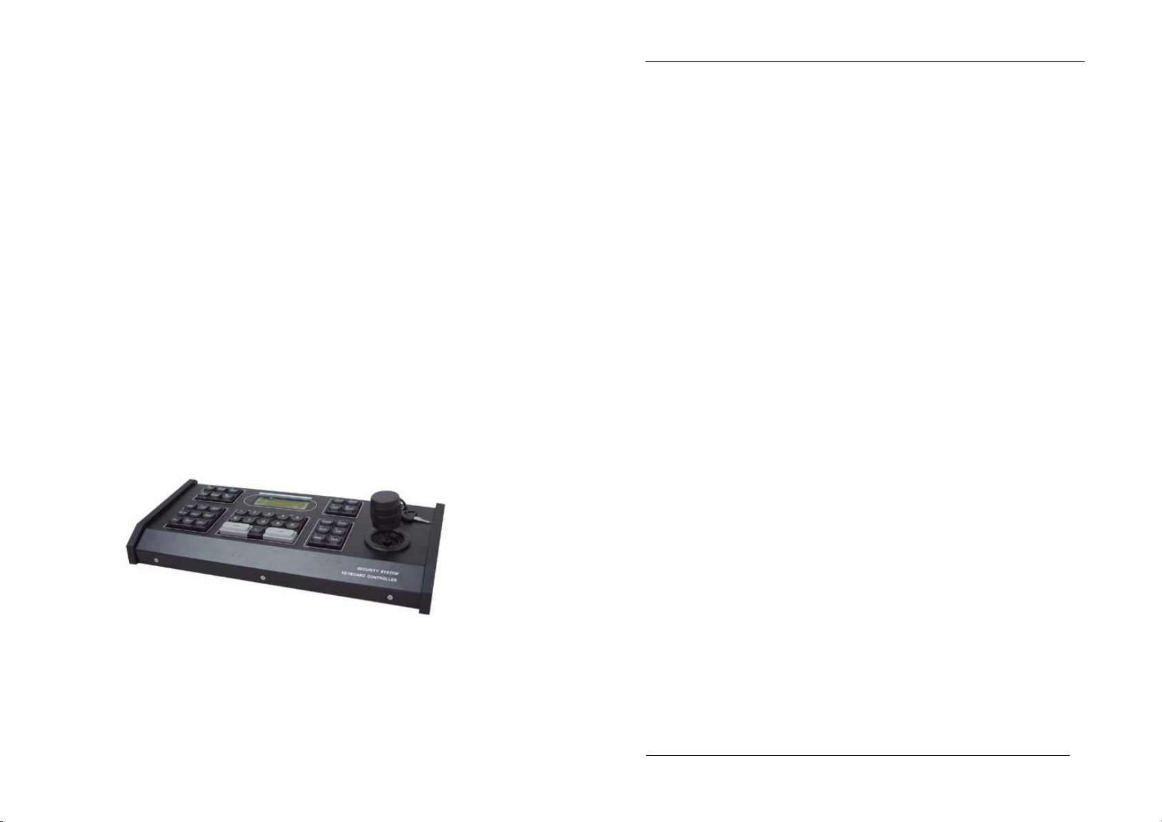
SYSTEM KEYBOARD
The system keyboard is a kind of operation keyboard used for the
matrix switching system. The system keyboard can call all cameras,
programmed monitor switching queues and control decoders. The LCD
can display system time, monitor number, camera number and
operation status. The system keyboard has the function of protection.
DISPLAY
NET :0 00 ARM : 000 0
CAM : 000 1
Description of key functions:
MON— select a monitor
CAM— select a camera
LAST— auto adverse-run switching
NEXT— auto positive-run switching
RUN— auto run switching
TIME— stop time switching
SALVO—synchronous run switching
HOLD— image storing
ON— function start
OFF— function closing
AUX— auxiliary function
SHOT—call preset point
ALARM—set alarm touch point
NET— select network matrix
ACK— function confirmation
- 3 / 21 -
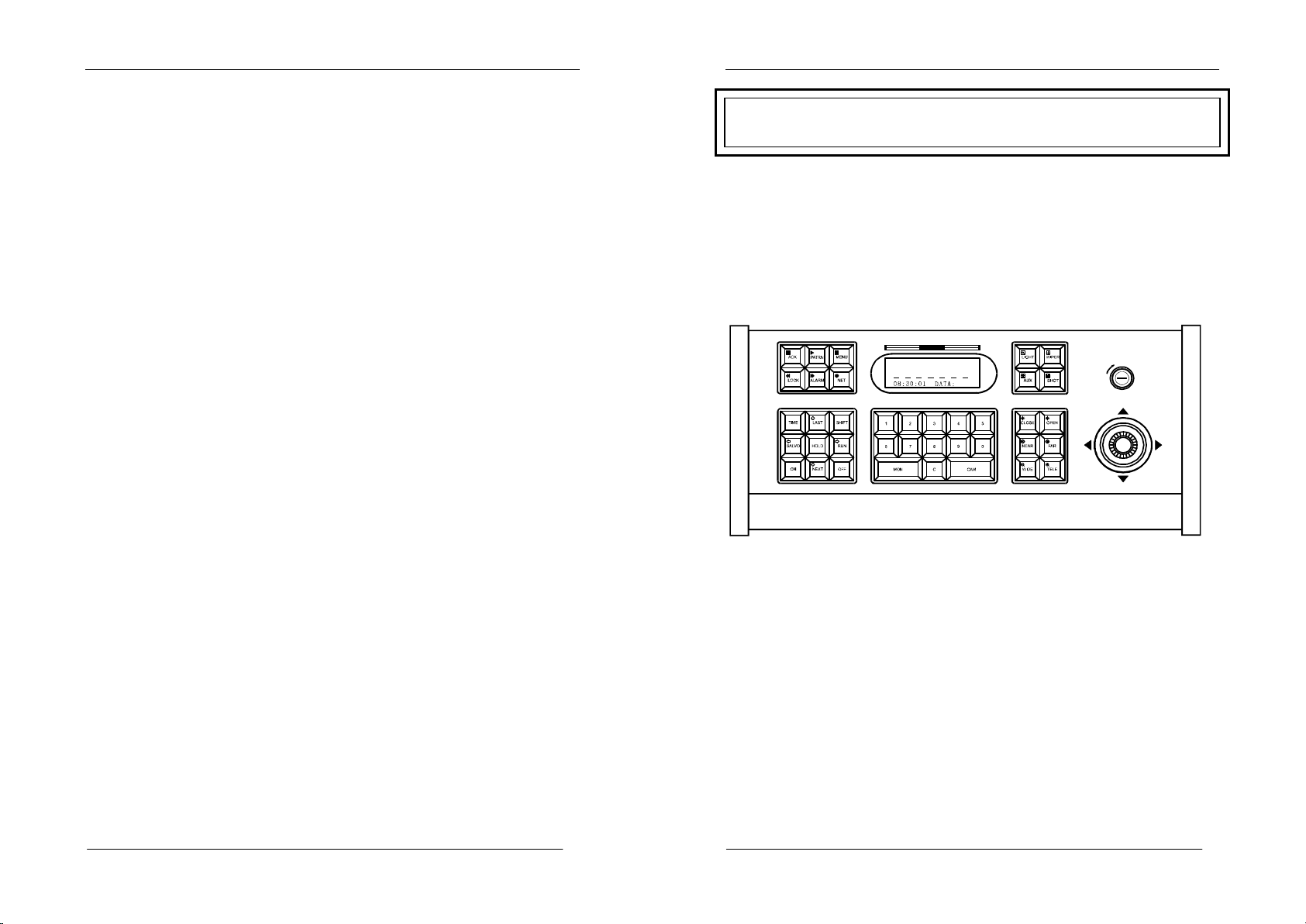
Page 3
User Manual of System Keyboard
MO N : 00 1
NE T : 00 0
AR M : 00 0 0
SHIFT—shift key
CLOSE—close lens iris (IRIS-)
OPEN— open lens iris (IRIS+)
FAR— regulate focus (FOCUS-)
NEAR—regulate focus (FOCUS+)
TELE— feature picture (ZOOM-)
WIDE— panorama (ZOOM+)
LIGHT—lighting control
WIPER—brush control
PATRN—image tour
LOCK—soft lock
MENU—menu programming
C— digital removal key
UNIVERSAL ZONE – control tilt direction
FIGURE ZONE – used for entering figures
Note: figures can be removed if
When a figure exceeds four places, the keyboard can reset automatically, and
display a new figure.
0 key is pressed for a little longer.
- 4 / 21 -
User Manual of System Keyboard
Part 1 Switching System of Control Matrix
1.1 Keyboard power-on:
Using the code switch at the front of the keyboard, set a keyboard code (see
Part 3). Provide power with a DC 12V power source through an interface box
and an eight-core flat wire, and connect the interface box to the
communication interface of the matrix mainframe properly. After power on,
the communication indicator (CODE) flickers (if it does not flicker, the
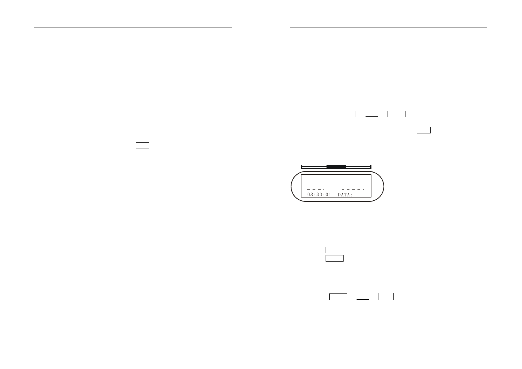
interface box is misconnected). Indication of “LOCK” in the status display
area requires to enter a 4-place keyboard password (the original password is
“0000”) as follows:
LOCK
+“****”+
OFF .
After inputting a password
correctly, “----”will appear in the status display area. After entering a
monitor number and pressing the confirmation key
MON
, the monitor display
area indicates the currently controlled monitor number, demonstrating that the
keyboard is under control.
DISPLAY
<L OC K >
<L OC K >
<L OC K ><L OC K >
CA M : 00 0 1
1.2 Locking keyboard operation
After keyboard operation, to prevent illegal operation, keep the
keyboard in a protective condition in the following way:
1.Press
2.Press
LOCK
ON
key;
key; “
LOCK
”will be shown on the status display
area.
1.3 Unlocking keyboard operation::::
Unlocking keyboard operation protection
Method:
password (the original password is “0000”).
LOCK
+“****”+
OFF
,where **** is a 4-place keyboard
1.4 Keyboard password setting::::
A keyboard password is a 4-place figure. To change a password
1.
Have the lock switch on “
PROG
”position;
- 5 / 21 -
Page 4
User Manual of System Keyboard
2.
Press
LOCK
key;
3.Enter a 4-place password
4.
Press
ACK
key;
5.
Have the lock switch on “
Note: if a password is forgotten, find it out through
the menu function of the matrix switching mainframe.
“****”;
OFF
”position;
KEYBOARD PASSWORD in
1.5 Monitor selection::::
To conduct video keyboard operation, connect the keyboard to the matrix
mainframe effectively. The camera can be operated successfully after selection
of a monitor and regulation of the camera.
1.
Enter the desired monitor number into the keyboard digital area;
2.After
MON
key is pressed,the monitor shows the new monitor
number in the monitor display area.
Example: call No. 2 monitor.
1.
Press
2
digit key.
2.
Press
MON
key.
At this moment, No.2 monitor is currently the controlled monitor.
1.6 Camera selection:
In the digital area, enter the desired camera number to be called (the
number shall have a corresponding video signal input).
Press CAM key. At this moment, the camera frame will be switched
to a designated monitor, and the camera will show the camera number entered
just now.
Example: No.1 camera is called to be shown on No. 2 monitor.
1.Press 2 digit key;
2.Press MON key;
3.Press 1 digit key;
4.Press CAM key. At the moment, No.2 monitor indicates the frame of
No. 1 camera.
1.7 Control decoder (remote control camera) :
Operations of the cameral tilt, lens, preset and auxiliary functions are
effective when the camera is regulated to the control monitor.
If the camera is programmed to be uncontrolled, the control of the camera
through the keyboard will be inoperative.
- 6 / 21 -
User Manual of System Keyboard
1.7.1 Operation tilt:
On the left of the keyboard, a vector rocker can be used to control the
direction of camera.
Operation:
1.
Regulate the to-be-controlled camera to the controlled monitor.
2.
Bias the vector rocker to the direction to which the picture is intended
to move, and control the direction of the camera.
3.
Loosen the vector rocker, stopping the directional operation of the
camera.
1.7.2 Lens control:
On the left of the keyboard there are a group of keys to control the
variable lens of the camera. The keys are:
CLOSE/OPEN
:used for iris control of the lens. The two keys can be used
to change the volume of light into the lens so as to get appropriate level
of video signal.
NEAR/ FAR
:used for focus control of the lens. The two keys can be
used to change the focal length of the lens so as to get clear pictures.
WIDE / TELE
:used for changing times of the lens. The two keys can be
used to change the times of lens focal variation so as to get wide-angle or
feature frames.
Operation:
1.
Regulate the to-be-controlled camera to the controlled monitor.
2.
Press the desired lens function key to control the lens.
3.
Stop the lens operation by letting out the key.
1.7.3 Tilt scanning operation;
Auto scanning::::Press
0
+
AUX
+
ON / OFF
and the tilt will
scan ON/OFF automatically.
Horizontal limit scanning:
1.
Regulate the to-be-controlled camera to the controlled monitor.
2.
Press
9
+
AUX
+
ON
to set the left limit of the tilt, and the
tilt starts rotation.
3.
Press
OFF
to set the left limit of the tilt, and the tilt returns.
4.
Press
0
+
AUX
+
OFF
to stop the horizontal limit scanning of
the tilt.
1.8 Control of intelligence Hi Speed Dome
1.8.1 Variable-speed horizontal and vertical movements: operate the vector
rocker, and the bias degree of operating arm is proportional to the
movement speed of the hi-speed intelligence ball, namely, the farther the
- 7 / 21 -
Page 5

User Manual of System Keyboard
operating arm deviates from the center, the faster the hi-speed
intelligence ball moves. Stop the direction operation of the hi-speed
intelligence ball by letting out the vector rocker.
1.8.2 Lens operation:
Press NEAR/ FAR keys to adjust focus of the lens;
Press WIDE / TELE keys to get panoramas or feature pictures.
1.8.3::::Setting preset position:
Select a camera, have the switch on the position of “
picture. After entering the preset position number defined by yourself, press
SHOT
key,then
ON
key. Adjust the picture, then continue the setting of
PROG
” and regulate the
next preset position, and finally have the lock switch on the position of
“
OFF
”.
1.8.4 Calling preset position:
Regulate the to-be-controlled camera to the controlled monitor. In the digital
area, enter the number of a desired preset frame, and press SHOT key, the
ACK key. The preset picture is displayed on the monitor. If no preset picture
is set in advance, there is no change on the picture of monitor.
1.8.5 Removal of preset position:
Select a camera, have the switch on the position of “PROG”. After entering
the preset position number, press SHOT key,then OFF key. Finally
have the lock switch on the position of “OFF”.
1.8.6 Setting tour queue:
After setting the preset position of the camera, use it in the tour queue.
1. After entering the number of tour queue in the digital area, press
PATRN key, then ON.
2. After entering the number of preset frame in the digital area, press
SHOT key, and add the first preset position to the set tour queue.
3. After entering the number of preset frame in the digital area, press
SHOT key, and add the second preset position to the set tour queue.
……
4. After entering the number of preset frame in the digital area, press
SHOT key, and add the last preset position to the set tour queue.
- 8 / 21 -
User Manual of System Keyboard
5. Press OFF key to stop setting the tour queue.
Note: Some intelligence High Speed Domes have no tour queue
functions. Therefore, this function depends on the intelligence Hi
Speed Dome.
1.8.7Operating the tour queue:
Regulate the to-be-controlled camera to the controlled monitor. In the digital
area, enter the number of a tour queue to run, press PATRN key, then press
ACK key. The camera will start to run the programmed picture of tour queue.
If no preset picture is set in advance, there is no change on the picture of
monitor.
1.9 Operation of auxiliary functions
In the keyboard, the AUX ON / OFF keys are used to control
auxiliary functions. The specific auxiliary functions and their numbers are as
follows:
1 + AUX + ON / OFF decoder auxiliary 1 ON/OFF;
2 + AUX + ON / OFF decoder auxiliary 2 ON/OFF;
3 + AUX + ON / OFF decoder auxiliary lighting
ON/OFF;
4 + AUX + ON / OFF decoder auxiliary brush
ON/OFF;
Operation:
Regulate the to-be-controlled camera to the controlled monitor.
Enter the number of the auxiliary function to be operated (1—4).
1.Press AUX key.
2.Press ON key to start the auxiliary function or press OFF key
to close the auxiliary function.
1.10 System free switching
Free switching is the condition where, after appropriate programming, a series
video inputs designated can be automatically shown on the monitor in
sequence, and each video input can display a switching queue of stop time set.
1.10.1 The free switching of the monitor can be programmed as follows:
1. Call the monitor number to be set as free switching.
2. Enter 2-240 seconds as the stop time of each camera.
3. Enter the start camera number for free switching.
4. Enter the end camera number for free switching.
5. The free switching of the camera starts running.
- 9 / 21 -
Page 6

User Manual of System Keyboard
Example: No. 3 monitor switches frames of No. 1—6 cameras for 2 seconds
of stop.
3 + MON .(select a monitor)
2 + TIME .(switch stop time automatically)
1 + ON .(start camera number)
6 + OFF .(end camera number)
1.10.2 Set the stop time of a camera in the free switching queue:
Operate according to the following steps:
1. Enter the required stop time (2-240 seconds).
2. Then press TIME key .
1.10.3 Run the free switching:
1. Enter 0 digit key .
2. Then press RUN key .
1.10.4 Add one camera to the programmed free switching queue:
Operate according to the following steps:
1.Press the camera number.
2.Press ACK key.
3.Press ON key.
1.10.5 Delete one camera from the programmed free switching queue:
Operate according to the following steps:
1. Press the camera number.
2. Press ACK key .
3. Press OFF key.
1.10.6 Stop the running of free switching:
By pressing n(non-zero key )+ CAM key, stop the running of free
switching , and retain the camera frame called for display.
Press 0 + RUN key to continue the free switching.
1.10.7 Increment/decrement single-step switching or changing the
direction of switching:
After pressing NEXT key,the switching direction will run in the form
of increment;
After pressing LAST key,the switching direction will run in the form
of decrement;
- 10 / 21 -
User Manual of System Keyboard
1.11 System program switching:
System program switching is the condition where, after appropriate
programming of the menu in the matrix mainframe, a series video inputs
designated can be automatically shown on the monitor in sequence, and each
video input can display a switching queue of stop time set.
1.11.1 Set program switching queue:
See the TOUR(program switching)under the menu function of
SWITCH(switching setting)in the mainframe.
1.11.2 Operate the program switching queue:
1.On the keyboard, enter the serial numbers 1-32 called for system
switching.
2.Press RUN key .
Example: No. 2 program switching will run on No. 3 monitor:
1.Enter the figure 3 ,,,,Press MON key for confirmation.
2.Enter the figure 2 ,,,,Press RUN key for operation.
1.11.3 Change the running direction of program switching:
After pressing NEXT key,the switching direction will run in the form of
increment;
After pressing LAST key,the switching direction will run in the form of
decrement;
1.11.4 Stop the operation of program switching:
By pressing HOLD key or n(non-zero figure)+ CAM key, stop the running
of free switching. HOLD key can have a picture to stay on a camera frame
being switched, while n(non-zero figure)+ CAM key can have a picture to
stay on a selected picture.
1.12 System synchronous switching
System synchronous switching means a group of camera frames can be shown
in sequence by switching to a group of continuous monitors and programmed
through the system setting menu.
- 11 / 21 -
Page 7

User Manual of System Keyboard
1.12.1 Setting the synchronous switching queue:
See the SALVOS(synchronous switching)item setting under the menu
function of SWITCH(switching setting)in the mainframe.
1.12.2 Operating the synchronous switching queue:
1. Set the first monitor of the synchronous switching monitor group as the
controlled monitor.
2. Enter 1-16 as the numbers of the system synchronous switching queue.
3.Press SALVO key. Redundant camera frames will not be shown
when the number of monitors in the synchronous switching queue exceeds the
largest monitor number.
1.13 System group switching
System group switching means groups of synchronous camera frames can be
shown in sequence by switching to a group of monitors and programmed
through the system setting menu.
1.13.1 Setting the group switching queue:
See the GROUP(group switching)item setting under the menu function of
SWITCH(switching setting)in the mainframe.
1.13.2 Operating the group switching queue:
1. Conduct the operation on any one of the monitors.
2.Enter the system group switching queue number 80+(group switching
constant 80+ group switching number)
3. Press SALVO key .
1.13.3 Stopping the operation of the group switching:
Enter the figure 0 , and press SALVO key, or press HOLD key to
stop the switching.
1.14 Alarm linkage:
Alarm function can automatically switch from video input to video output and
control alarm linkage.
Alarm linkage ON: enter the alarm contact number, press ALARM key, then
ON key.
Alarm linkage OFF: enter the alarm contact number, press ALARM key,
then OFF key.
User Manual of System Keyboard
1.15 Alarm port in the protective area:
The system can set and cancel the protection of 16 built-in contact interfaces
or the alarm points of the alarm mainframe.
Alarm port setting: have the lock switch on “PROG”position, enter the
alarm contact number, press ALARM key, then ON key.
Alarm port cancellation: have the lock switch on “PROG”position, enter
the alarm contact number, press ALARM key, then OFF key.
Alarm port answer: have the lock switch on “PROG”position, enter the
alarm contact number, press ALARM key, then ACK key.
1.16 Alarm port condition:
Inquiring alarm point condition: enter 9 7 , press AUX key ,
then ON key.
Closing alarm point condition: enter 9 7 , press AUX key ,
then OFF key.
1.17 Sound ON/OFF:
Keyboard sound can be ON or OFF using the following operation.
Operation: enter 9 9 , then press AUX key .
- 12 / 21 -
- 13 / 21 -
Page 8

User Manual of System Keyboard
OFF
PROG
SYST EM KEYB OARD
MON :0 01
1234567
8
Part 2- Control of Digital Camera and Frame Processor
2.1 Entering the modes of digital camera and frame processor:
On the keyboard, press SHIFT key,“SHIFT” appears on the LCD display
area, with the keyboard entering the shift function. At this moment, you can
control the digital camera and frame processor. Using corresponding keys, get
relevant functions from the panel.
2.2 Quitting the modes of digital camera and frame processor:
On the keyboard, press SHIFT key,and “----” appears on the LCD display
area. After that, the keyboard will quit from the keyboard shift function, and
return from the modes of digital camera and frame processor.
2.3 Selection of digital camera and frame processor:
In the modes of digital camera and frame processor:
Enter the figure 1 ,press MON key, then control the first digital
camera and frame processor;
Enter the figure 2 ,press MON key, then control the second
digital camera and frame processor;
Enter the figure 3 ,press MON key, then control the third digital
camera and frame processor;
Enter the figure 4 ,press MON key, then control the fourth digital
camera and frame processor……
2.4 Control of digital camera and frame processor:
DISPLAY
NET :0 00 ARM: 00 00
CAM :0 00 1
User Manual of System Keyboard
Part 3 Connection Setting
3.1 Setting the working mode of keyboard
Eight-place binary code switch. Pushing up the switch means 1 (ON)
and down 0 (OFF).
8 7 6 5 4 3 2 1
ON
OFF
PORT
CODE
3.1.1 Working mode of keyboard matrix:
This working mode is mainly used in the matrix mainframe system. To enter
this mode, change No. 8 terminal in ID to “OFF”; the terminals 1, 2, 3 and 4
are setting switches for keyboard code numbers.
Table of contrast between keyboard code number and code:
Keyboard
code
number
Code position Keyboard
1 2 3
4
code
number
Code position
1 2 3 4
00 0 0 0 0 08 0 0 0 1
01 1 0 0 0 09 1 0 0 1
02 0 1 0 0 10 0 1 0 1
03 1 1 0 0 11 1 1 0 1
The functions of digital camera and frame processor on the keyboard are
identical to those on the panel. See the instructions on specific functions of
digital camera and frame processor.
- 14 / 21 -
04 0 0 1 0 12 0 0 1 1
05 1 0 1 0 13 1 0 1 1
06 0 1 1 0 14 0 1 1 1
07 1 1 1 0 15 1 1 1 1
Note: all keyboard code numbers must be different, or otherwise keyboard
operation may fail.
- 15 / 21 -
Page 9

User Manual of System Keyboard
3.1.2 Working mode of keyboard system:
This working mode is mainly used in direct-control decoders and intelligent
Hi Speed Domes. To enter this mode, change No. 8 terminal in ID to “ON”.
Baud rate selection setting: the baud rate of the keyboard can be set by
changing terminals 5 and 6 in ID. Baud rate is selected to assure that the
keyboard has the same data transmission rate as the control equipment.
User Manual of System Keyboard
3.2 Schematic drawing of connection between keyboard and matrix
mainframe
The keyboard joint-box is connected to the communication interface with a
plain shielded two-core twisted-pair cable, 1200 meters long at most.
DC 12V power line:white—DC12V;black —GND.
Position of
code position
5 6
Baud rate
Position of
code position
5 6
Baud rate
1 0 1200 1 1 4800
0 1 2400 0 0 9600
Control protocol: under the same baud rate, decoders and intelligence High
Speed Domes in different control protocols by changing No. 1, 2, 3 and 4 in
ID.
No. 1 2 3 4 Control protocol
1 1 0 0 0 PELCO-D
2 0 1 0 0 PELCO-P
3 1 1 0 0 ALEC
- 16 / 21 -
- 17 / 21 -
Page 10

User Manual of System Keyboard
3.3 Schematic drawing of keyboard decoder connection:
The keyboard joint-box is connected to the communication interface of the
system with a plain shielded two-core twisted-pair cable, max. 1200 meters
long.
User Manual of System Keyboard
3.4 Schematic drawing of connection between keyboard and small
system
The keyboard joint-box is connected to the communication interface of the
system with a plain shielded two-core twisted-pair cable, max. 1200 meters
long.
- 18 / 21 -
- 19 / 21 -
Page 11

User Manual of System Keyboard
3.5 Schematic drawing of connection between keyboard and
intelligence Hi Speed Dome
The keyboard joint-box is connected to the communication interface of the
system with a plain shielded two-core twisted-pair cable, max. 1200 meters
long.
User Manual of System Keyboard
Part4 USER ULTRAK PROTOCOL
User Ultrak protocol / Baud-9600
- 20 / 21 -
- 21 / 21 -
 Loading...