

Page 1
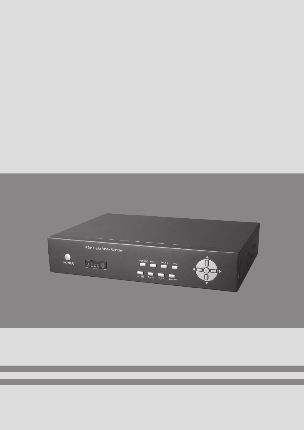
Embedded Digital Video Recorder
USER MANUAL
Page 2

>>Stand-alone DVR User Manual
CONTENTS
Chapter1:Specifications and connector definition ····································································3
1.1 Parameter ·····························································································································3
1.2 DVR appearance ··················································································································4
1.3 Connector definition·············································································································4
1.3.1 Front panel button definition: ····················································································4
1.3.2 Panel combination key definition···············································································5
1.3.3 Front panel pilot lamp definition:···············································································5
1.3.4 Rear panel··················································································································5
1.4 Remote Controller instruction ······························································································7
Chapter2 System Installation and Notes·····························································································9
2.1 Caution·································································································································
2.2 Package c
2.3 Connection ·························································································································10
2.3.1 Video connection ·····································································································10
2.3.2 Alarm input and output ····························································································10
2.3.3 RS-485/RS485 connection······················································································· 11
2.4 HDD installation ················································································································12
2.5 GND connection·················································································································12
Chapter3 Operation··························································································································12
3.1 System operation illustration and glossary··········································································12
3.2 Start-up·······························································································································13
3.3 Exit system·························································································································13
3.4 Status bar operation············································································································13
3.5 Other operations·················································································································15
3.6 Main menu ·························································································································16
3.6.2 VIDEO SET ············································································································19
3.6.3 RECORD SET······································································································20
3.6.4 Alarm set ·················································································································21
3.6.5 File Management·····································································································24
3.6.6 User Management····································································································25
3.6.7 NET SET·················································································································26
3.6.8 Storage Management ·······························································································28
3.6.9 System Info···········································································································28
hecking ···············································································································10
9
1
Page 3

>>Stand-alone DVR User Manual
Chapter4 WAN connection···············································································································30
4.1 PPPOE ·······························································································································30
4.2 Router forwarding ··············································································································30
2
Page 4
Chapter 1:Specifications and connector definition
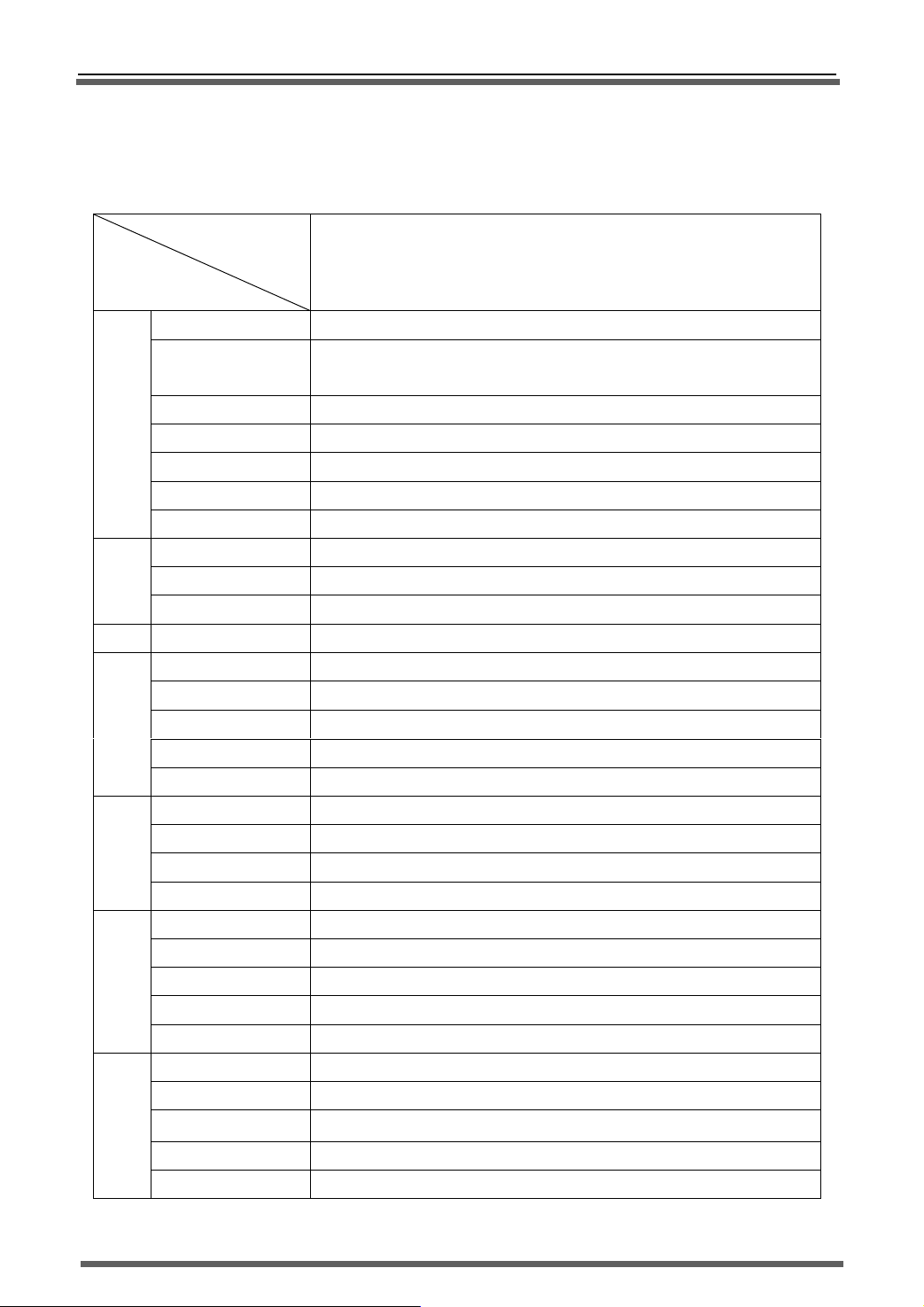
1.1 Parameter
Model
parameter
Compression H.264
Video source
Video
Audio
Rec. Recording mode
Storage and
Network
I/O
Control way
Live resolution
Recording resolution
Input 16 CH BNC
Output
Video standard
Audio input 4 CH
Audio output 1 CH
Compression G.723
Playback 8CH
HDD 2X SATA
HDD volume 1TB
HDD format FAT32
Backup
Net port
protocol
Net browsing method
CMS
Alarm input 16 CH
Alarm output 4 CH
RS485 1x RS485, support PTZ control
RS232 1
USB 2
Remote control Support
Mouse USB mouse
Panel
>>Stand-alone DVR User Manual
16 CH DVR
PA L : 400 frame
NTSC: 480 frame
D1(704×576)
CIF(352×288)
1 CH BNC,1 CH VGA(resolution 1024×768,60Hz)
PA L、NTSC adjustable
Manual,Schedule,Motion detect,alarm recording
USB device backup,network backup,Local HDD backup
Ethernet10/100Base-T,RJ45
UDP/IP,TCP/IP,IGMP(multicast),DNS&DHCP client,PPOE,DDNS
Client software,IE browsing
Preview 36CH video in client software,manage 255 pcs DVR
Support(optional)
Network control Support
3D keyboard control Only support VC protocol 3D keyboard
3
Page 5
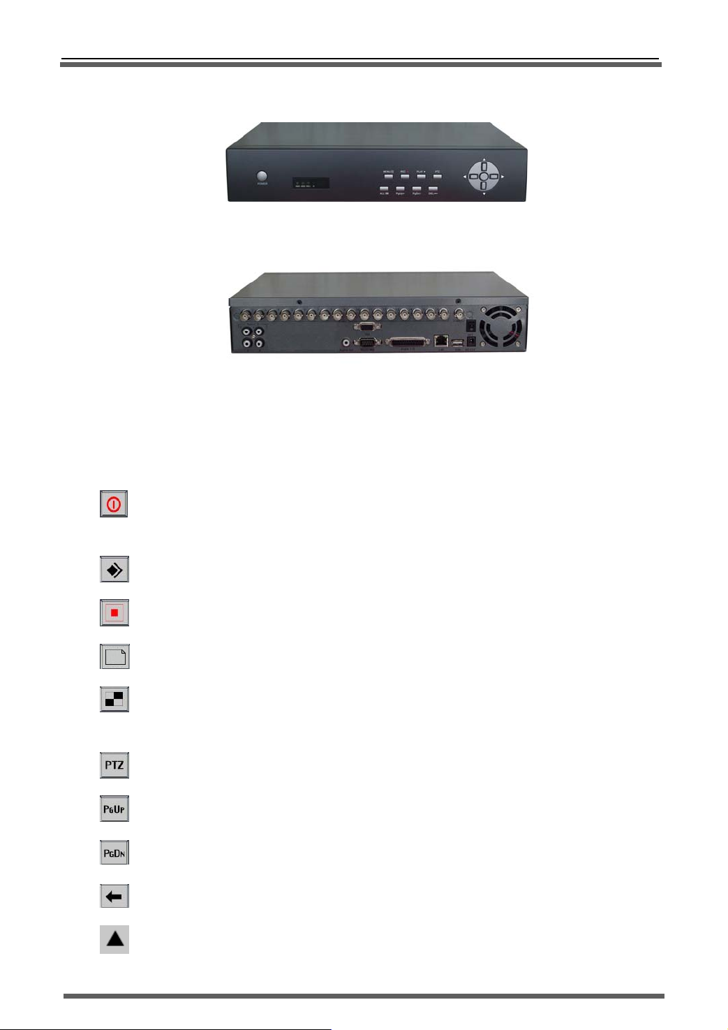
1.2 DVR appearance
1.3 Connector definition
>>Stand-alone DVR User Manual
Pic.4 Small case with button
Pic.5 Rear panel
1.3.1 Front panel button definition:
Power: Turn ON/OFF system. If system is closed by DVR software options, you should
press this button to start the system.
Menu: Enter system menu and return.
Record: Enter recording setting menu.
Files: Enter video file management menu.
Mode: witch quad ,signal picture and PIP display mode;Long time press as the
switching key of other mode, please refer to “Panel combination key definition”
PTZ: Enter PTZ control interface
Page Up: Turn up.
Page Down: Turn down.
Back Space
Up: Move up cursor.
4
Page 6
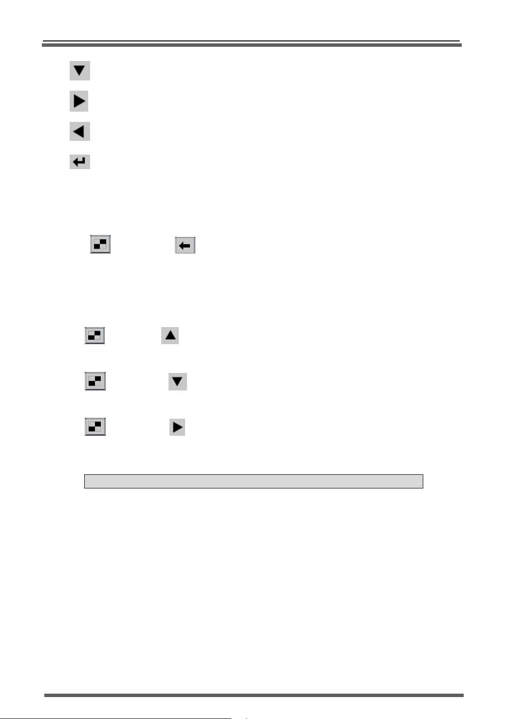
Down: Move down cursor
Right: Move right cursor
Left: Move left cursor
Enter
1.3.2 Panel combination key definition
A、ON/OFF key voice:
(Mode) + (Back space) : Long time press “Mode” button till you heard
“DiDi” sound and then press “Backspace” button to ON or OFF key voice.
B、Switch video output channel:
>>Stand-alone DVR User Manual
(Mode) + (Up):Long time press “Mode” button till you heard “DiDi” sound
and then press “Up” button to switch to VGA output.
(Mode) + (Down):Long time press “Mode” button till you heard “DiDi”
sound and then press “Up” button to switch to CVBS output
(Mode) + (Right):Long time press “Mode” button till you heard “DiDi”
sound and then press “Up” button to switch to digital YUV output
Note: This mode is used to switch to LCD display on DVR all-in-one model.
1.3.3 Front panel pilot lamp definition:
PWR:Power indicator light,It is green color when stand-by and red when work.
HDD:HDD work indicator light.
REC:Recording indicator light, it is on when DVR is recording.
IR: IR receiver and front panel key indicator light
1.3.4 Rear panel
A、 VGA:VGA output port,Output resolution 640x480、800x600、1024x768 optional.
B、 RS232/485: RS232/485 connector, pin definition refer to Pic.6 (RS232/485 pin
definition).
5
Page 7

>>Stand-alone DVR User Manual
Pic.6 RS232/485 Pin definition
C、 VIDEO
1) Video In:1~16
2) Video Out: CVBS
CH CVBS Video input;
Video output。
D、 AUDIO
1) Audio In:1~16CH
2) Audio Out:
E、 LAN:10/100M
F、 USB:USB2.0
network port。
port.
Audio input;
Audio output。
G、 Alarm:Alarm signal port:
25 pin jack in top line from left to right, the pins definition are 1,2…13,on bottom
line from left to right,the pins definition are 14,15…25。
1) Alarm output(Relay out):four group, they are:
Alarm output 1(Relay out 1)N1D-----------------------------------------------4
Alarm output 1(Relay out 1)N1U-----------------------------------------------17
Alarm output 2(Relay out 2)N1D-----------------------------------------------3
Alarm output 2(Relay out 2)N1U-----------------------------------------------16
Alarm output 3(Relay out 3)N1D-----------------------------------------------2
Alarm output 3(Relay out 3)N1U-----------------------------------------------15
Alarm output 4(Relay out 4)N1D-----------------------------------------------1
Alarm output 4(Relay out 4)N1U-----------------------------------------------14
Relay output 120VAC/1A 24VDC/1A, Normal(Relay break),alarm(relay
colse)。
2) Alarm input(Alarm In):16CH alarm input pins are:
Alarm In 1--------------------------------------------------------------------------- 13
Alarm In 2--------------------------------------------------------------------------- 25
Alarm In 3--------------------------------------------------------------------------- 12
Alarm In 4--------------------------------------------------------------------------- 24
Alarm In 5--------------------------------------------------------------------------- 11
Alarm In 6--------------------------------------------------------------------------- 23
Alarm In 7-------------------------------------------------------------------------- -10
Alarm In 8-------------------------------------------------------------------------- -22
Alarm In 9--------------------------------------------------------------------------- 9
6
Page 8

>>Stand-alone DVR User Manual
Alarm In 10------------------------------------------------------------------------- 21
Alarm In 11------------------------------------------------------------------------- 8
Alarm In 12------------------------------------------------------------------------- 20
Alarm In 13------------------------------------------------------------------------- 7
Alarm In 14------------------------------------------------------------------------- 19
Alarm In 15------------------------------------------------------------------------- 6
Alarm In 16-------------------------------------------------------------------------18
(COM)GND------------------------------------------------------------------------ -5
16CH alarm level input,input impendence 22K,window compare voltage(3.0V
to 4.18V)。
H、 Power:Power source.,AC110V/220V,50~60HZ。
I、 Power switch(I/O):ON/OFF system power.
J、 :GND
1.4 Remote Controller instruction
Remote Controller
Pic.7
(1) Remote Controller key definition
1. Figure key(0~9):Input figure and letter. In preview model, figures 1~9 are
used to switch 1-channel.
2.
3.
Power:ON/OFF system power
PTZ:Enter PTZ control interface
4.
5.
Device Number:Enter device No. input dialog box
Back Space:Delete the current input
7
Page 9
>>Stand-alone DVR User Manual
6.
7.
8.
9.
10.
11.
12.
13.
Page Up:Turn up, reduce the number
Page Down:Turn down、add the number
Menu:Enter main menu / return
ESC:Return, exit the operation
Mode:Switch quad ,single picture and PIP display mode;Long time press
as the switching key of other mode; please refer to “Remote controller
combination key definition”.
Shift:Switch channel display position.
Files:Enter video file management dialog box
Information:Check system info
14.
15
16
17.
18.
19.
Mute:ON/OFF system audio output
. Alarm clear:Clean system alarm prompting information
. Record:Enter recording setting dialog box
Play/Pause
Frame Forward:Single frame play
Speed back:Speed back play key,there are 4 levels:1X、2X、3X、
4X
20.
Speed Forward:Speed forward play key,there are 4 levels: 1X,2X、
3X、4X
21.
22.
Up:Cursor move up
Down:Cursor move down
8
Page 10
>>Stand-alone DVR User Manual
23.
24.
25.
Left:Cursor move left
Right:Cursor move right
Enter
(2) Remote controller combination key definition
1、
(Mode) + (mute) : Long time press “Mode” button till you heard
“DiDi” sound and then press “Mute” button to ON or OFF key voice.
2、
(Mode) + direction key(Up, Down, Right):Switch output channel.
Long time press “Mode” button till you heard “DiDi” sound and then press
figure key to choose video output channel:Press “
press “
”->VGA output,press“ ”->YUV output。
Note:This mode is used to switch to LCD display on DVR all-in-one model
”-> CVBS output,
Chapter 2 System Installation and Notes
2.1 Caution
◆ Power supply
※ The applicable power supply for this machine is AC100~240V 50~60Hz or 12VDC/4A, Please use our
special power supply come with the machine.
※ Please keep the power plug away from socket if you don’t use this machine for long time。
◆ Safety
※ as indoor equipment, this machine shouldn’t be put it in moist or dusty place In order to prevent from
danger of short circuit and electric shock.
※ Once any solid or liquid come into the machine, please cut off power immediately,
And then ask the technician to inspect it before you use it again.
※ If there is any malfunction with the machine, you should ask the technician to examine and repair or
contact with the dealer, please don’t ever mend it by your self.
◆ Installation place
※ You should select the right place where the air can circulate over the machine thus can prevent the
machine from overheating.
※ This machine shouldn’t be installed in hot places near radiator or vent-pipe, or some other places where is
9
Page 11

>>Stand-alone DVR User Manual
insolated or dusty and moist, as well as those places with strong magnetic field or with mechanical shake
and strike.
◆ Copyright protection
※ Please don’t infringe the related right of the third party when you make image recording program.
※ Any change or modification on this machine without our permission might destroy the machine and cause
many inconvenience to the user
.
2.2 Package checking
After unpack the carton, please check whether the host and spare parts are in good condition,
if anything wrong, please stop using and contact your supplier immediately. Also please check
whether the following items are complete:
◆ User manual X 1 PCS
◆ IR remoter X 1 PCS
◆ Remoter batteries X 2 PCS
◆ AC
power cable X 1 PCS
◆ HDD bracket and screws X 1 PCS
◆ Client manager software CD X 1 PCS
◆ 9pin COM port connector X 1PCS
◆ 25pin alarm port connector X 1PCS
◆ USB mouse x 1pcs
2.3 Connection
2.3.1 Video connection
A、Video input connection:
System support 16CH CVBS input, input resistance is 75Ω,BNC connector。
B、
Video output connection:
System support 1CH CVBS output,output resistance is 75Ω,BNC connector。
a)
System support 1CH VGA output,resolution 1024x768 60Hz / 800x600 60Hz / 640x480 60Hz
b)
optional
。
Note: When VGA and CVBS output connected,system can only support one connection, otherwise the video
output will be abnormal caused by load resistance mismatch..
2.3.2 Alarm input and output
A、Sensor connection:
a)
Sensor adopt N.C. output contact
10
Page 12
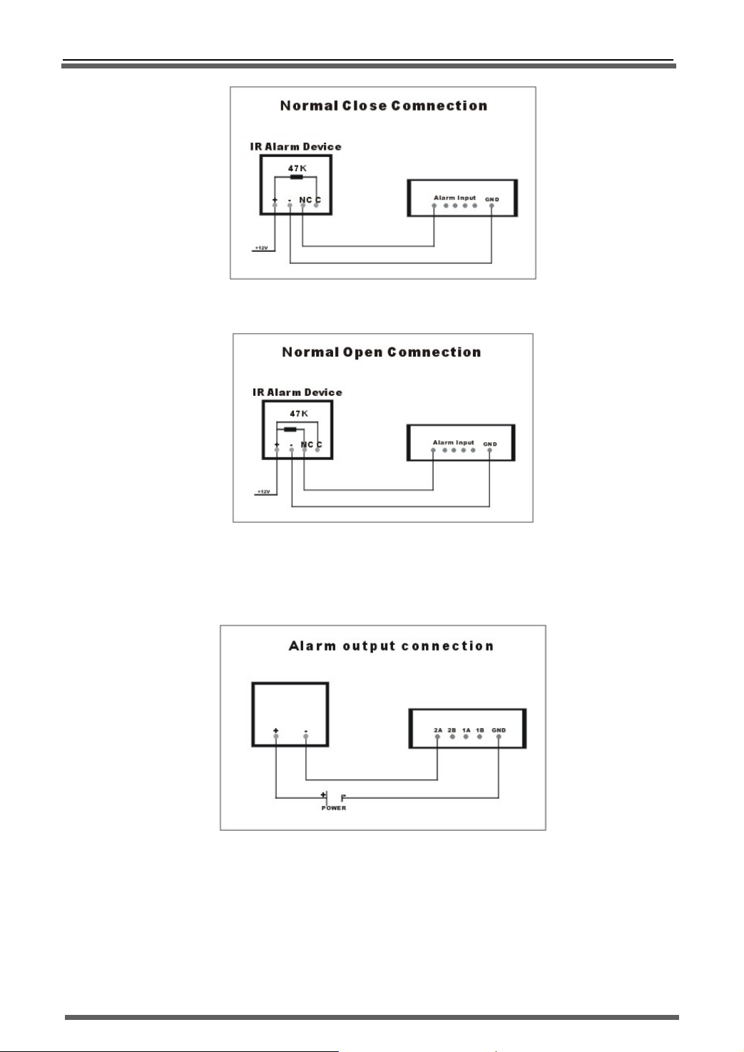
Alarm input connection 1-N.C.
b) Sensor adopt N.O. output contact
>>Stand-alone DVR User Manual
Alarm input connection 1-N.O.
B、 Alarm output connection:
Alarm output connection
2.3.3 RS-485/RS485 connection
Host have one standard RS-485/232 port, pin definition please refer to Pic.3. RS485 is used to control PTZ
decoder and camera, RS232 is used to debugging software and other communications expanding.
Host builds in many PTZ/camera protocols, it can connect 4 PTZ decoders/cameras at the same time, and each
channel corresponds to one. Default PTZ decoder/camera decoder is same as its channel number.
11
Page 13

>>Stand-alone DVR User Manual
2.4 HDD installation
System only supports 2 SATA HDD,and set the jumper on SATA I(Limit to 1.5Gb/s
Operation )mode. After that, use bracket to fix the HDD in the DVR, connect the power cable and
date cable.
2.5 GND connection
After connect the signal cable, please connect the screw with the grand to protect the
host.
Chapter 3 Operation
3.1 System operation illustration and glossary
1) Selection box:
Used to point the checked operation, yellow frame, and press direction key to move it.
2) Checked:The position of selection box is the current operation position. Move the box to every target
means check this item.
3) Click:After checked the items, press “OK” button to click this object.
4) Soft keyboard:Checked edition box, press “OK” button to pop-up soft keyboard. You can do input
work via this keyboard.
Clink:Such as ENTER、 etc .“clink” this button to realize “Confirm”、“Cancel” and “enter
5)
next page” function.
6) Edit box:used to input figure、letter etc, it include text input box and figure input box.
Text input box:Select the text input box, such as the "host name" amendment etc. Input the text in
Figure input box: Such as time set, host No. set etc. Input the text in Software or the figure on IR
Software or the figure on IR remoter.
remoter. Also support page up “
descending.
”、page down“ ”key to increasing or
Drop-down box :Only support page up “ ”and page down“ ”key to rolling option.
7)
8)
List Box:Used to list the file and other items. Support pitch on single line and page up, page down.
12
Page 14
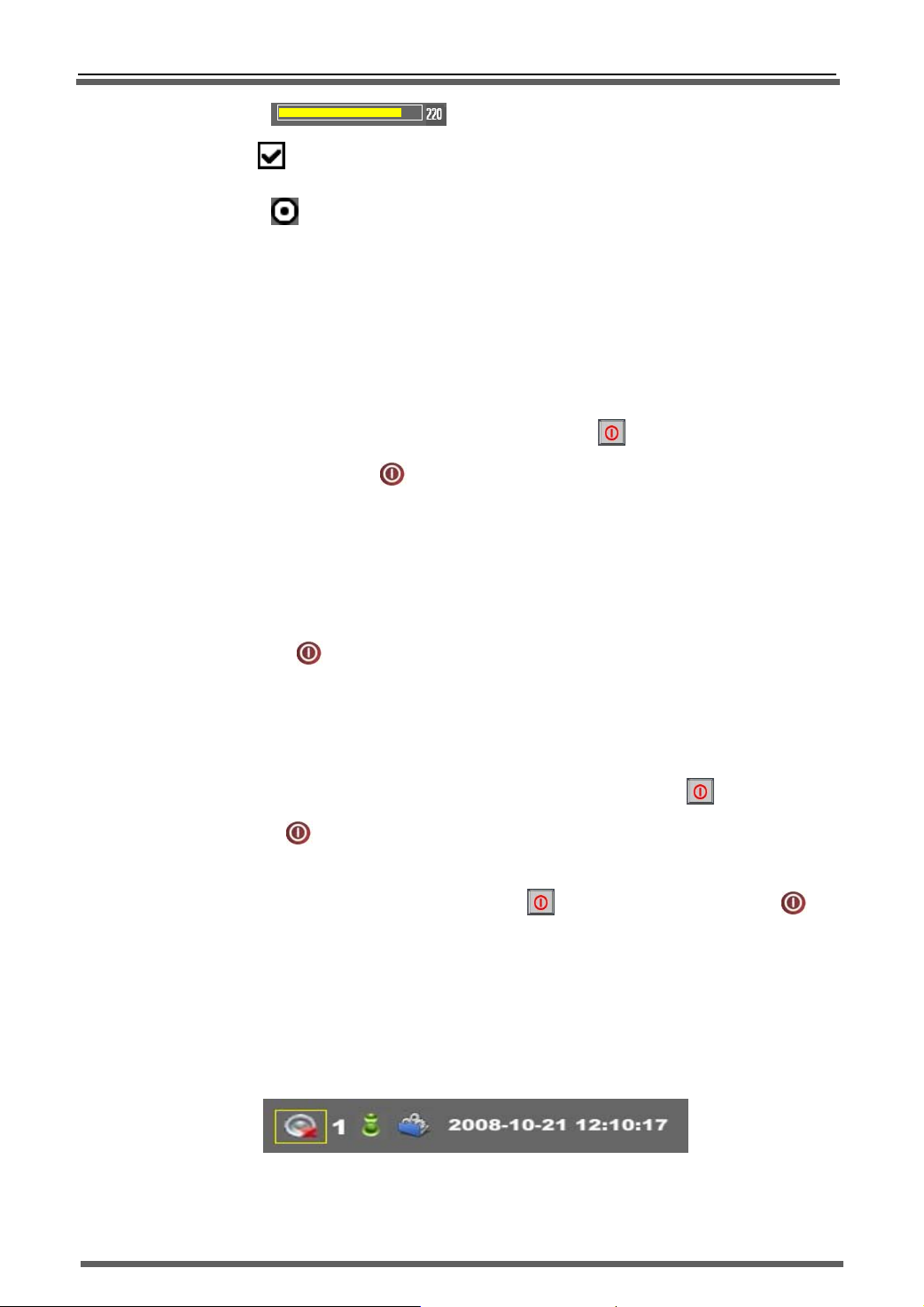
9)
Progress Bar :Press left and right key to increase and reduce the value.
10)
Check box :choose and press “OK” to confirm it.
11)
Radio button :Make a mutually exclusive choice in same list or group.
12)
Soft keyboard:press “OK” button in edit box to pop-op soft keyboard.
3.2 Start-up
1) Start system:Insert 12V adapter output connector into DVR power port, set the power switch(on
back panel) on “ON” position, now the PWR indicator on front panel is light, when its color is green,
>>Stand-alone DVR User Manual
system is stand-by (default working status).Press the power key “
front panel or the power key “ ” on IR remoter, the power indicator will change into red, system
2)
will turn into working status; When indicator is red, system will turn into working status after power
it.
Host NO. isn’t 0:If the host No. isn’t 0 and when you want to start the system in IR remoter, please
3)
follow below way:
4)
Press power key “ ” on the IR remoter till you heard “DIDI” two prompt sound,input the host No.
And then press “OK”. If the host No. is match, the system will start.
3.3 Exit system
1) Normal shutdown:When system is in working status, press the power key “ ” on front panel or
the power key “ ” on the IR remoter to pop-up system close dialog box, press “OK” button, the
system will turn into stand-by status.
2)
Forced shutdown:Long time press the power key “ ” on front panel or the power key “ ” on
the IR remoter, system will be forced shutdown.
” on
3.4 Status bar operation
When system running, exit the operation interface and main interface, the status bar will
display in the bottom left corner. It will show the system mute audio monitor and login status, also
include system info query/ alarm/backup and system clock, as below
Pic.11 Status Bar
13
Page 15
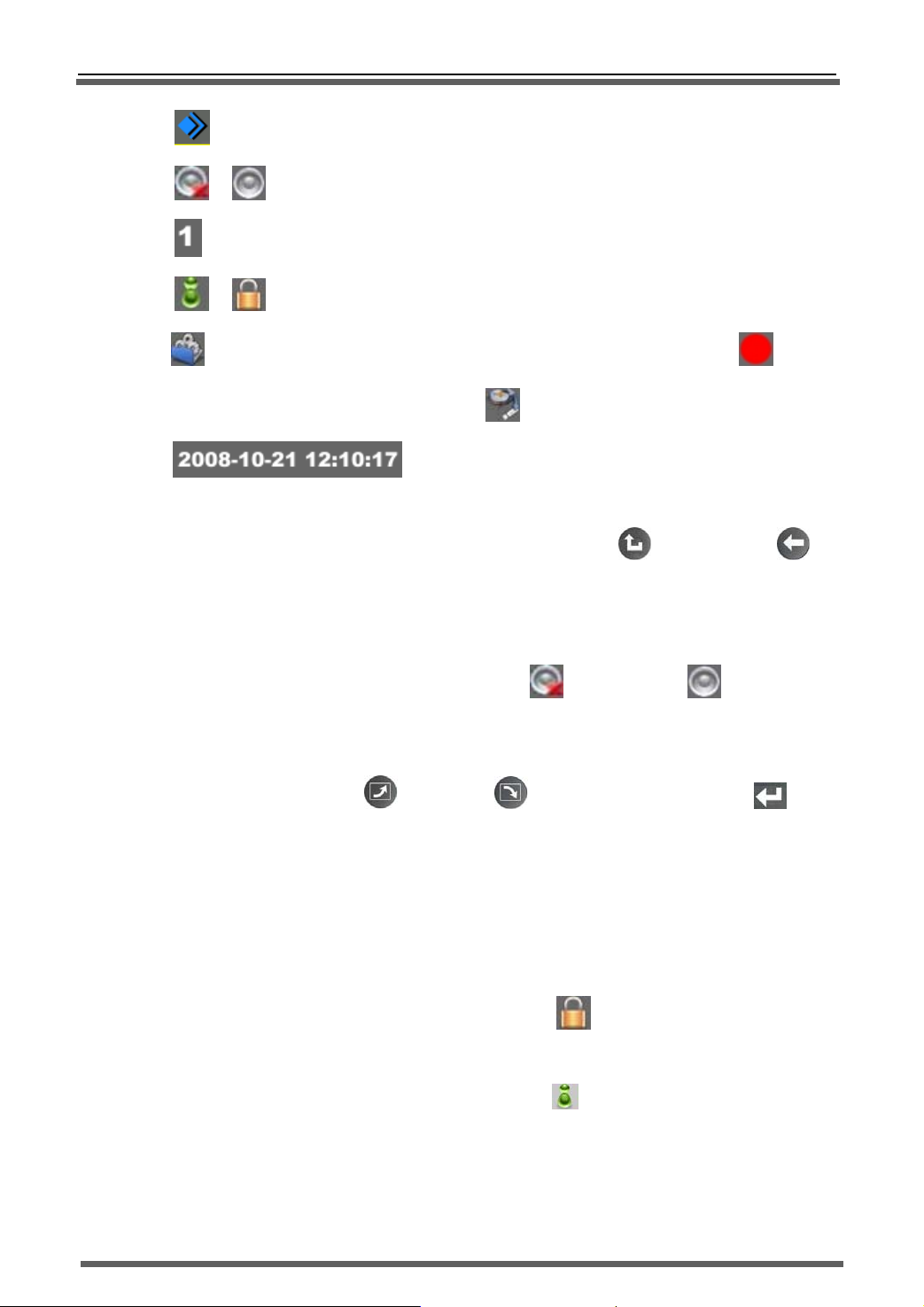
>>Stand-alone DVR User Manual
:Start menu button, press it to bob up start menu.
/ :Mute ON/OFF button
:Video/Audio monitoring status and display mode option
/ :Login/Lock button
:System info button, When alarm incident occurred show alarm status button:“ ”。When
system backup the data in the background show
“ ”
:Time and date setting button
1) Display/Hide
In preview status, press any key to display status bar. Press return “ ”or backspace key“ ” to
hide it.
2) Mute
Pitch on “Mute” icon, press “OK”, system will mute “ ”or open the voice“ ”.
3) Video/Audio monitoring status and display mode option
Pitch on monitoring select box, directly input the channel No. to switch to this channel and display in
single picture; press pageup“ ”or pagedown“ ”to switch picture position; press “ ”button
to switch display mode: 16CH->9CH->8CH->6CH->Quad->Single->PIP-> cycle
4) Login/Lock
After start system, system is in lock status, and the user can only switch the channel and display mode
in panel and IR remoter. If you want to do other operation, you should login system and after that, you
can do relevant operation in authorities.
System Login
a)
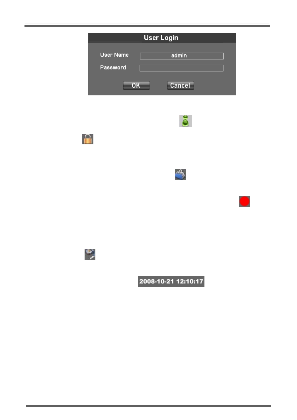
On status bar, move the cursor to LOGIN/LOCK icon ,press “OK” to pop-up login dialog
box, as below. Input the user name and password and press “OK” to enter login status, the
LOGIN/LOCK icon will change into login status icon
When system is locked, any operation that needs to be authorized will trigger pop-up login dialog
box. Now the user should login system and then continue his operation.
.
(Note:no password
in new DVR)
14
Page 16
>>Stand-alone DVR User Manual
Pic.12 User Login
System Lock
b)
On status bar, move the cursor to LOGIN/LOCK icon“ ”,press “OK” to turn into lock
status “ ”.In login status, if user do not do any operation in 2 minutes, the system will turn
into lock status automatically.
5) SYSTEM INFO
On status bar, move the cursor to system info icon“ ”,press “OK” to pop-up the system
information checking dialog box.(Refer to “System info” chapter).
When alarm occurred, the system info icon will change into alarm prompt button icon “
this button to pop-up alarm information query dialog box. (Refer to “System info”/“alarm query”
chapter).
When system is doing backup in background,the system info icon will change into backup prompt
button icon“
”,press this button to pop-up the backup prompt information.
6) Time and date setting
Move the cursor to time setting button“ ”to pop-up system time setting
dialog box. (Refer to “System info”/“time setting” chapter)
3.5 Other operations
”, press
1) Host number operation:
Start sy stem:If the system had been set the host No., that‘s to say the host No. is not 0, when
a)
you want to start system, the host No. should match. Detailed start method please refer to “Start
system”/“Start system when the host No. is not 0”.
b)
Match IR remoter:If the system hare the host No., that‘s to say the host No. is not 0, when the
IR remoter control this DVR after it operated other host (not 0 host number), you should do IR
remoter match and then you can control this DVR by that remoter .The match purpose is to
control several hosts in one IR remoter. Match method::Press host No., the system will pop-up
15
Page 17
>>Stand-alone DVR User Manual
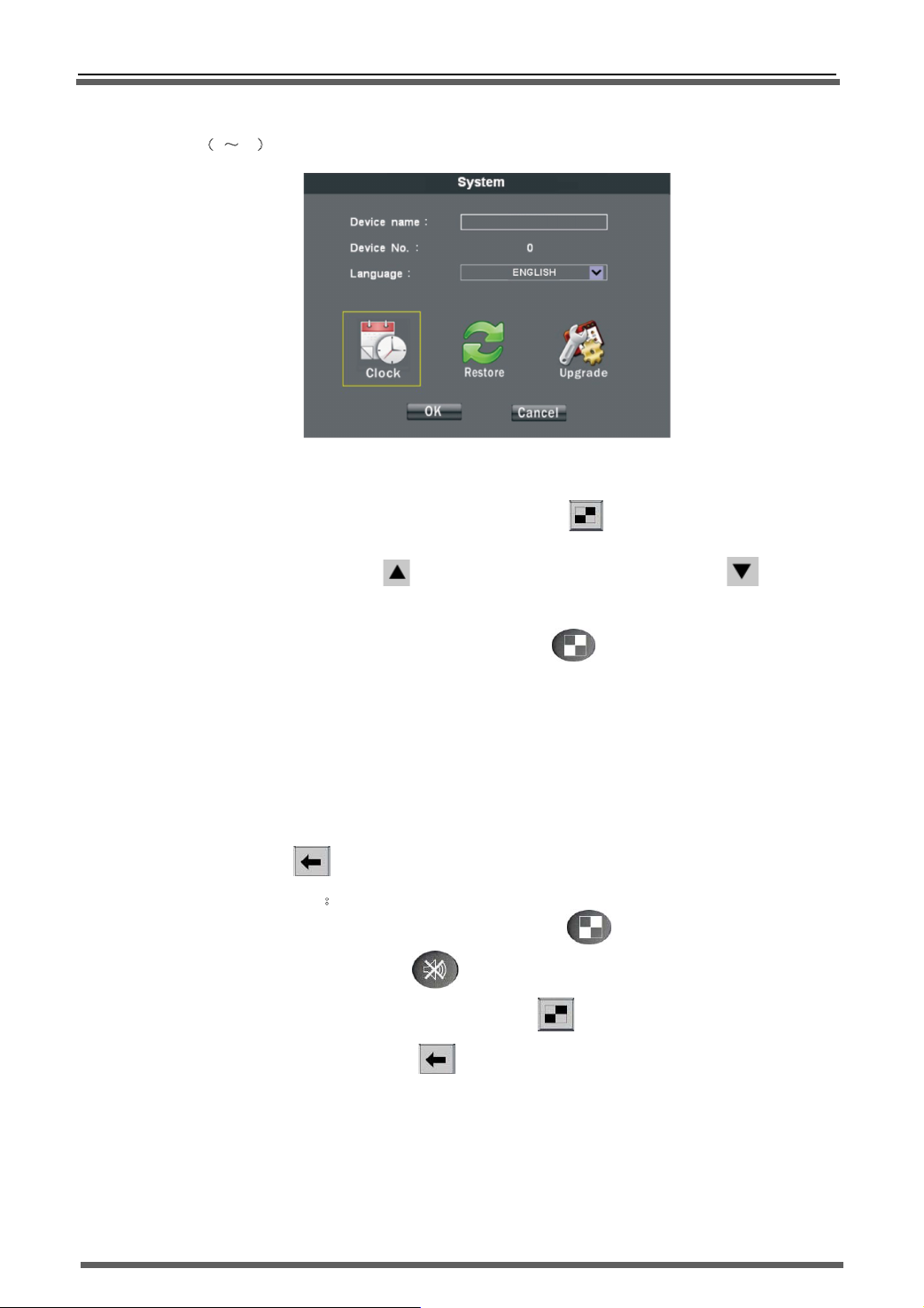
host No. match dialog box after “DIDI” two sound, as follow: Input the host number in “Input host
0~99)”edit box and press “OK” to confirm. Please refer to the oval box in the picture.
No.(
Pic.13 Host No
2) Video output channel switch
a) Front panel operation:Long time press mode button“ ” till you heard “DIDI” two sound,
and then press up button“
CVBS output.
”to choose VGA output, or press down button “ ” to choose
b) IR remoter operation:Long time press mode button“ ”,till you heard “DIDI” two sound,
and then press figure key to choose video output channel:1->CVBS output,2->VGA output,
3->YUV output.
3) Storage device format
Enter “Main menu”/“Storage management”,pitch on the device that need to be formatted, press
backspace button“
” to format the chosen device. After the format, the file format is FAT32.
4) ON/OFF key voice:
a)
IR remoter operation:Long time press mode button“ ”till you heard “DIDI” two sound,
and then press mute button “
Panel operation:Long time press mode button “ ”,till you heard “DIDI” two sound, and
b)
then press backspace button “
” to turn on or turn off the key voice.
” to turn on or turn off the key voice.
3.6 Main menu
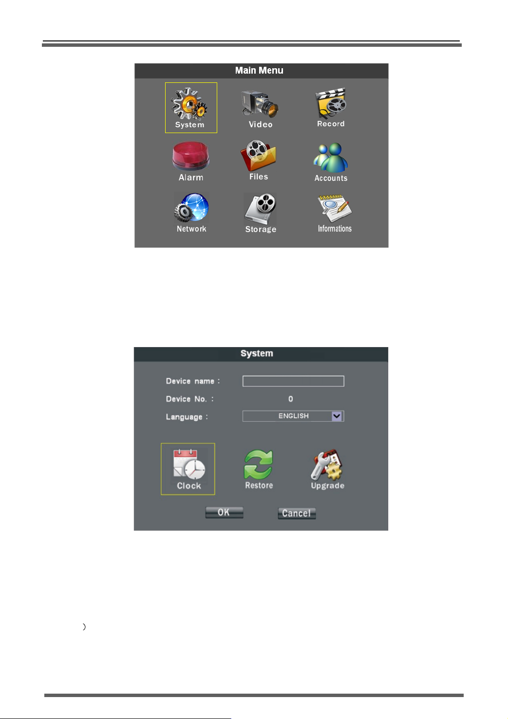
Press menu button to enter main menu interface, pitch on the relevant icon button and press
“OK” to enter the corresponding menu item.
16
Page 18
>>Stand-alone DVR User Manual
Pic.14 Main Menu
3.61. System Set
In “System Set” page, you can set the host name, host number and language. In its sub-menu, you can set
system time, recover the factory settings and upgrade the system software.
Pic.15 System Set
1) Name:input and amend host name
2) Number:Amend the local host number
3) Language:choose the system language
4)
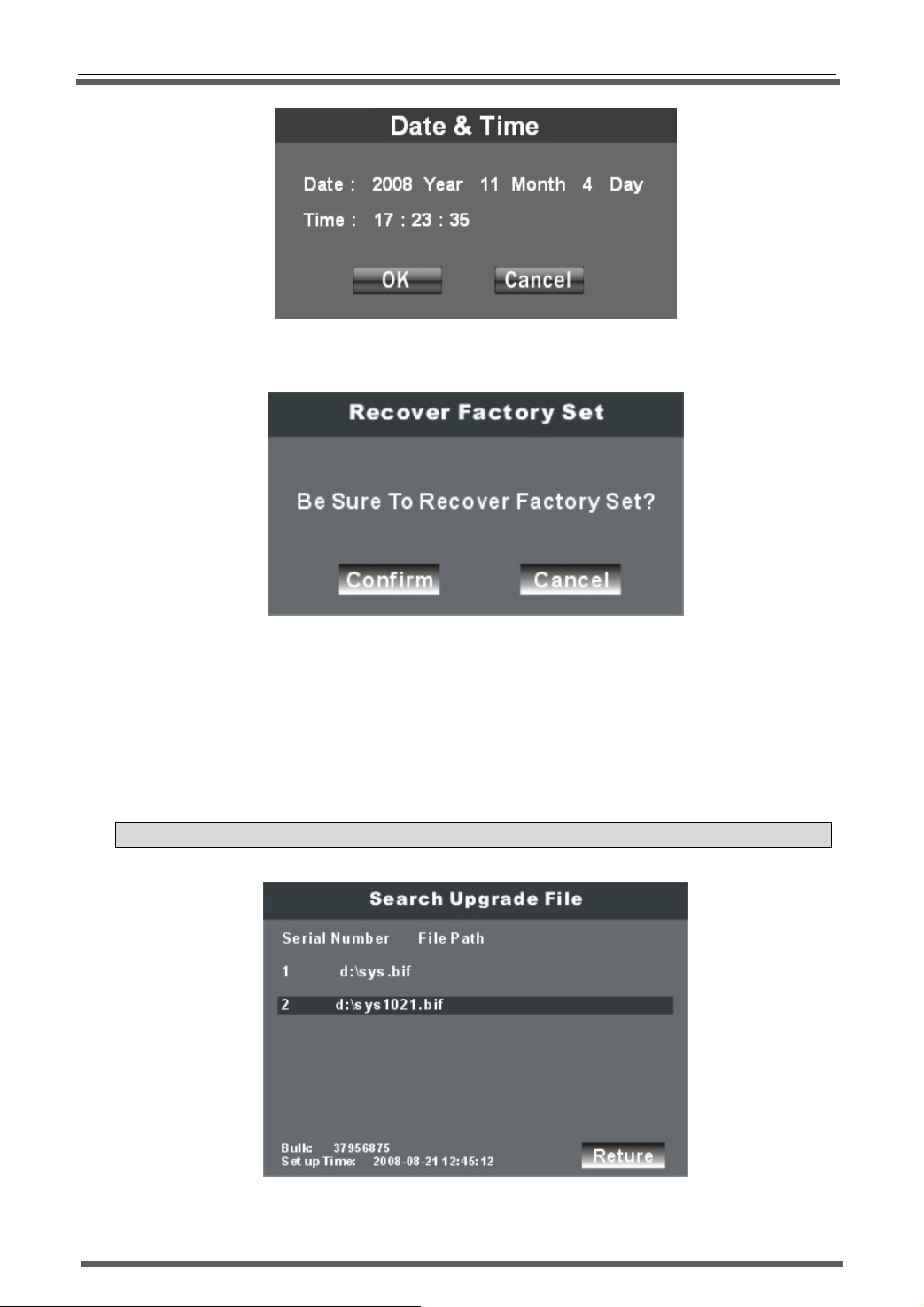
Time set:Presses “Time Set” button to pop-up the time setup dialog. As below:
17
Page 19
>>Stand-alone DVR User Manual
Pic.16 Time Set
5) FACT.SET: press “FACT. Set” button to pop-up the “recover factory set” dialog. As below:
Pic.17 Recover Factory Set
After recover factory set, the host number, video format, recording setting parameter etc. will not
change.
6) Upgrade:Copy the system upgrade file(*.bif)to your Flash disk, and insert it into USB port of DVR, press
“upgrade” button to pop-up “Search upgrade file” dialog as below: Choose the right upgrade file, press
confirm button to pop-up “Upgrade Confirm” dialog. The process of upgrading will last about 1 minute
and the system will automatically restart, after the completion of the upgrade system.
NOTE:You can not cut off the power when upgrading, otherwise the DVR system will collapse.
Pic.18 Search Upgrade File
18
Page 20
>>Stand-alone DVR User Manual
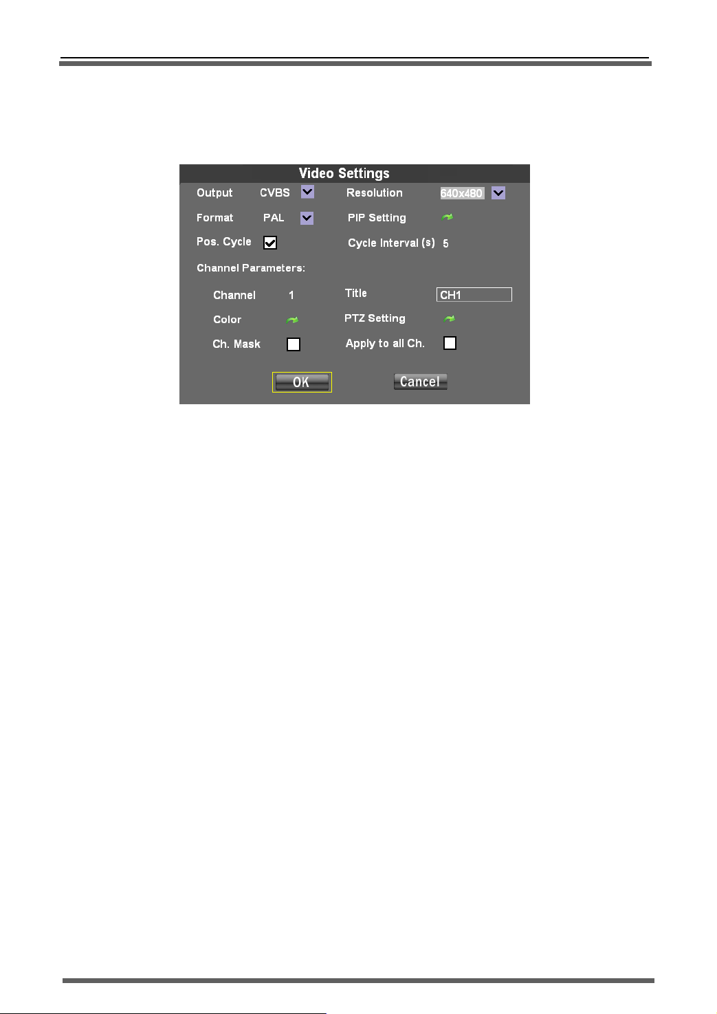
3.6.2 VIDEO SET
Set the system video properties; include the output channel, video format, PIP property, video
cycle parameter, video channel title, video color parameter.
VIDEO SET menu as below:
Pic.19 VIDEO SET
1) Video Output:choose output port “CVBS”,press “PGUP” or “PGDW” to choose
CVBS、VGA、YUV three output Way.
If CVBS output, the resolution bar will be gray, that means disable.
If VGA output,the resolution can be:640x480、800x600、1024x768.
If YUV output,the resolution can be:640x480、800x600、1024x768.
YUV output is digital video output way, it is used to drive digital LCD screen directly.
If you change the output way, the system need to be restart to enable it.
2)VIDEO FROMAT:
You can choose PAL or NTSC as your system format. If you change the system format, system will be
restarted
3) PIP setting:
Choosing the corresponding channel, when set the PIP, this channel will displayed on the top of the
screen.
4) POS.CYCLE:
Enable image cycle, choose cycle interval, the picture will automatically be cycle displayed in selected
time.
Channel parameter:
5)
Channel number:To select the appropriate channel(1~16)
a)
Channel title:Amend channel title
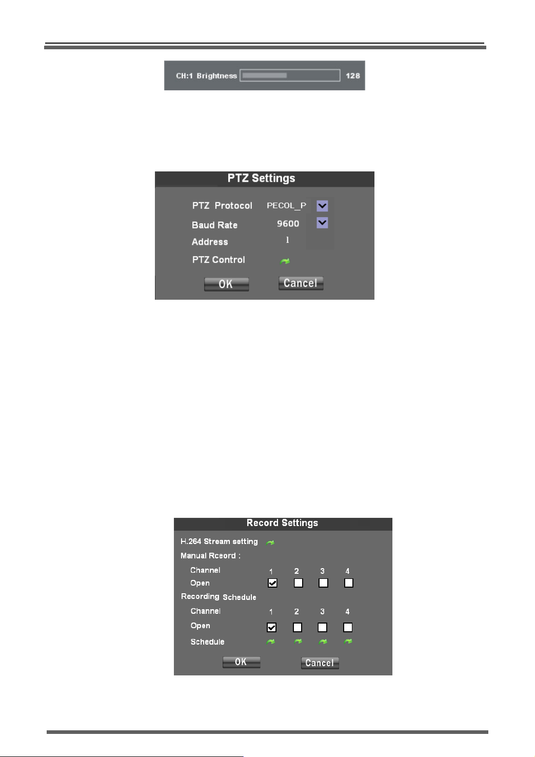
b)
Color parameter:To adjust the appropriate channel color parameter(Brightness、contrast、
c)
chroma 、saturation), press color parameter amendment button to enter color parameter
amendment page, as below:
19
Page 21
>>Stand-alone DVR User Manual
Pic.20 Progress bar
Press left or right button to adjust parameter values, press UP or DOWN button to switch
parameter type, press PGUP or PGDW to switch channel
CH MASK:Select to shield this channel
d)
PTZ setting:Enter PTZ setting interface
e)
Pic.21 PTZ SET
PTZ SET:In this page, you can choose protocol of PTZ which associate with this channel, the
baud rate and PTZ ID code. Default PTZ ID code is same as the number of channel that the
PTZ associated with.
PTZ CTRL:Press this button to enter PTZ control interface. You can control it via operation
panel. In this interface, you can set and call the preset point, can control the PTZ
UP/DOWN/LEFT/RIGHT run, can control the zoom, focus and aperture ,can control the PTZ
cruising.
Apply to all CH.:choose this item and press confirm, you can copy this channel setting to
f)
others channel.
3.6.3 RECORD SETTINGS
Set the recording bit stream、record mode etc
Recording mode choose:You can choose Manual recording, Timing recording and Alarm recording.
Pic.22 Record Setting
20
Page 22
>>Stand-alone DVR User Manual
a) Manual recording:
After choose the channel, this channel will start to recording under scheduled parameters (refer to
recording parameter setting), and you should manual stop the recording if you need to, the method
is to anti-election and confirm it.
b) Schedule Recording
First you should set the recording time period and then turn on this channel recording. When in
scheduled time period, the system will start recording automatically till the time period over.
Time period setting: press relevant channel time period setting button to enter setting page.
Please be noted that the time period can not be in two days.
c) Alarm recording:
Refer to alarm setting
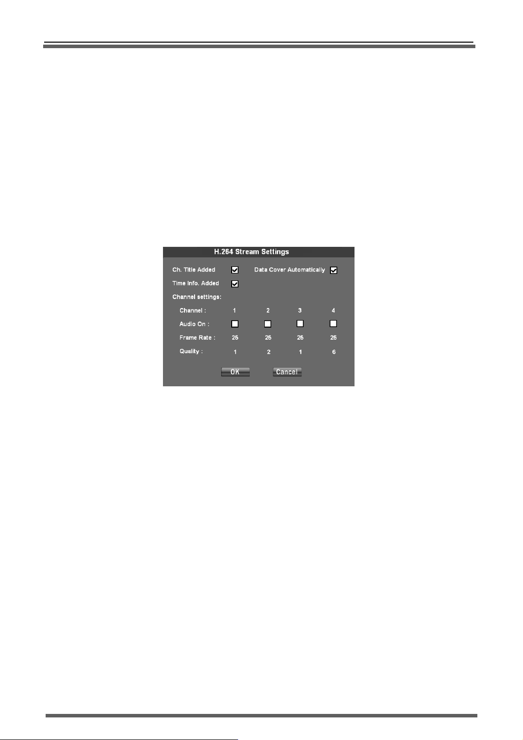
2) Bit stream parameter setting:setting interface as below.
Pic.23 Stream setting
a) CH title Added:Add the channel title into bit rate, so that the recording file and long range
preview picture will have channel title information.
b)
Time Info. Add:Add the time into bit rate, so that the recording file and long range preview.
Picture will have time information.
c)
Data Cover Automatically:When HDD is full, new recording file will automatically cover old
d)
files from beginning.
e)
Add audio:Video and audio recording simultaneously, can remote monitoring voice.
Frame rate setting:you can set recording frame rate,PAL format from 1~25FPS optional,
f)
NTSC format from 1~30FPS optional.
Image quality level:There are 6 level image quality. 1 is the best,6 is the worst。The higher
g)
level of image quality, the greater the stream. The more clear image, the greater the share of
network bandwidth and disk space.
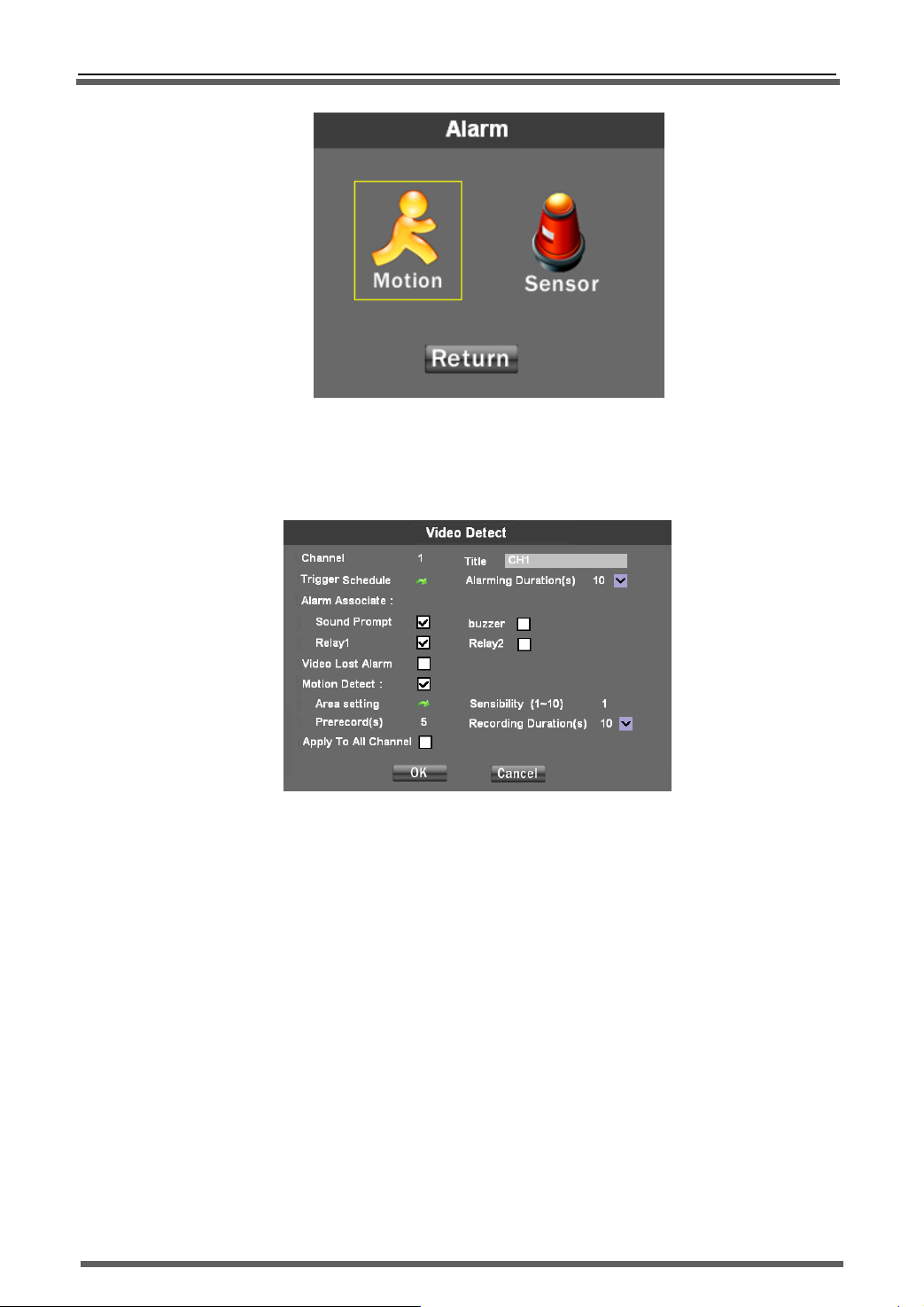
3.6.4 Alarm set
Set the host alarm trigger channel and relevant trigger condition, setting interface as below:
include “motion ” and “sensor” setup:
21
Page 23
>>Stand-alone DVR User Manual
Pic.24 Alarm set
● Motion:
Set video lost alarm, motion detection alarm trigger condition and associated channel. Setting interface as
below:
图 25 Video Detect
Channel No.:Choose the channel that need to be set and the channel title will automatically
a)
display in the behind
b) Trigger schedule:Set the trigger time periods.
c) Alarming Duration:Set the alarm duration. After triggered alarm, system will output the alarm
signal till you clean it by manual or the end of pre-setting alarm duration.
d)
Alarm Associate:
>
Sound prompt: After triggered alarm, system will output “du…du …” warning tone.
>
Buzzer:After triggered alarm,the buzzer on the machine will output “Di ...Di... Di”
warning tone.
>
Relay:After triggered alarm,system will close the switch of relay to connect the outer alarm
system.
e)
Video lost alarm:Unlock video lost alarm, when video signal lost, system will trigger alarm.
f)
Motion Detect:
>
Sensibility:Set the video motion detect sensibility,1~10 levels optional,level 10 is the
highest ,level 1 is the lowest。The higher-level set, the more sensitive when
motion detected.
22
Page 24
>>Stand-alone DVR User Manual
>
Prerecord:Set the prerecord time. After motion detect triggered alarm,
>
Recording duration:After motion detect triggered alarm, system will on-going record for the
set duration time
>
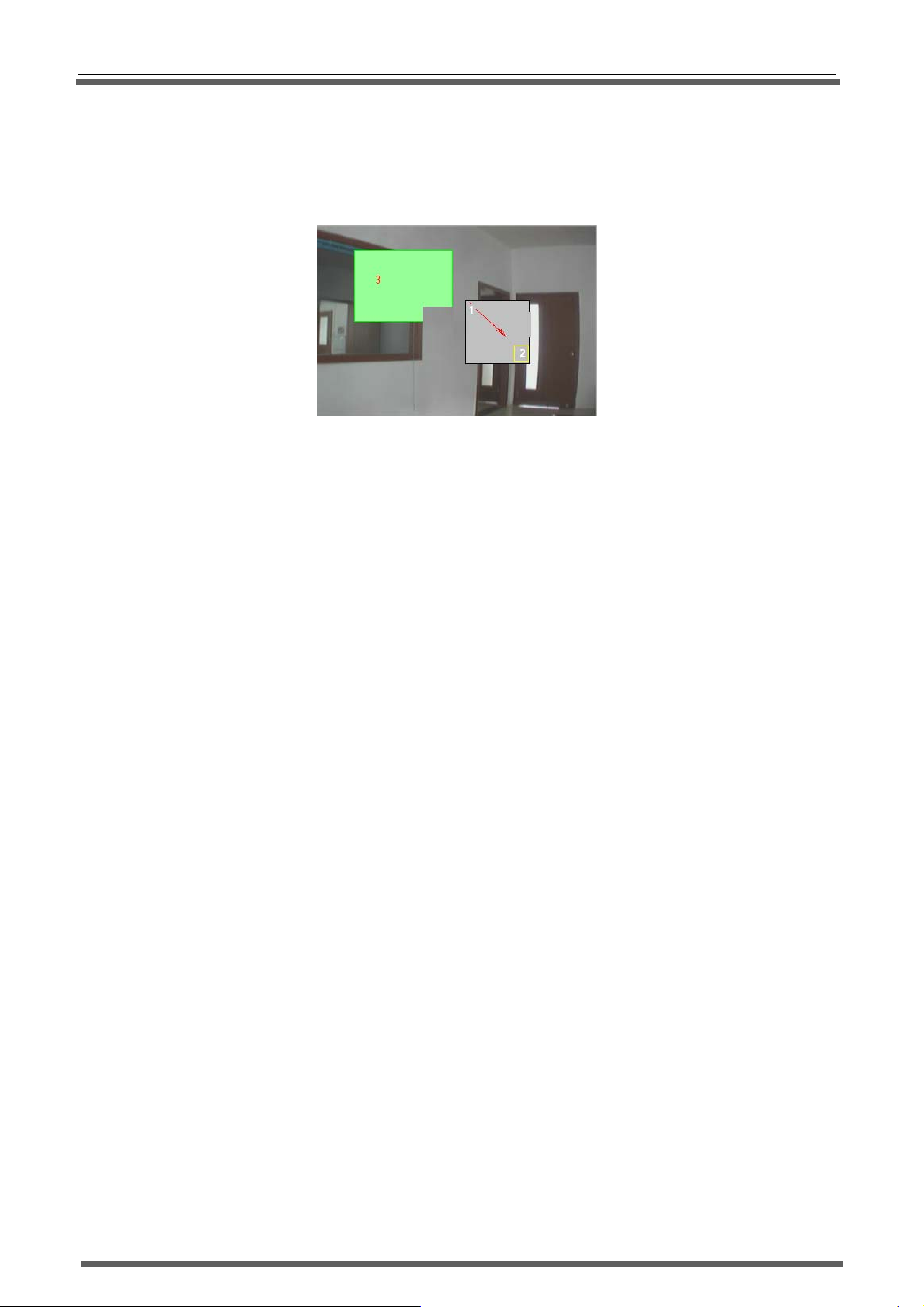
Area setting:Set the motion detect area. Press setup button to enter the setup interface, as
below::
Pic.26 Video detect area setting
Area setting:press direction button to move the curser to the detected area starting point, and
press “Enter” button to confirm it, refer to the “1” position on above picture.
After the confirmation of starting point, press direction button to set the detecting area, refer to the
“2” position on above picture. Press “Enter” button to finish the setting, the selected area will
become to green color, refer to the “3” position on above picture. Use same method to set other
detecting area.
Area Edit:Moving the selection box to the appropriate location in the selected area, use
above-mentioned area selection way to edit the detection area.
Apply to all channels: Apply this video detection parameter setting to all channels.
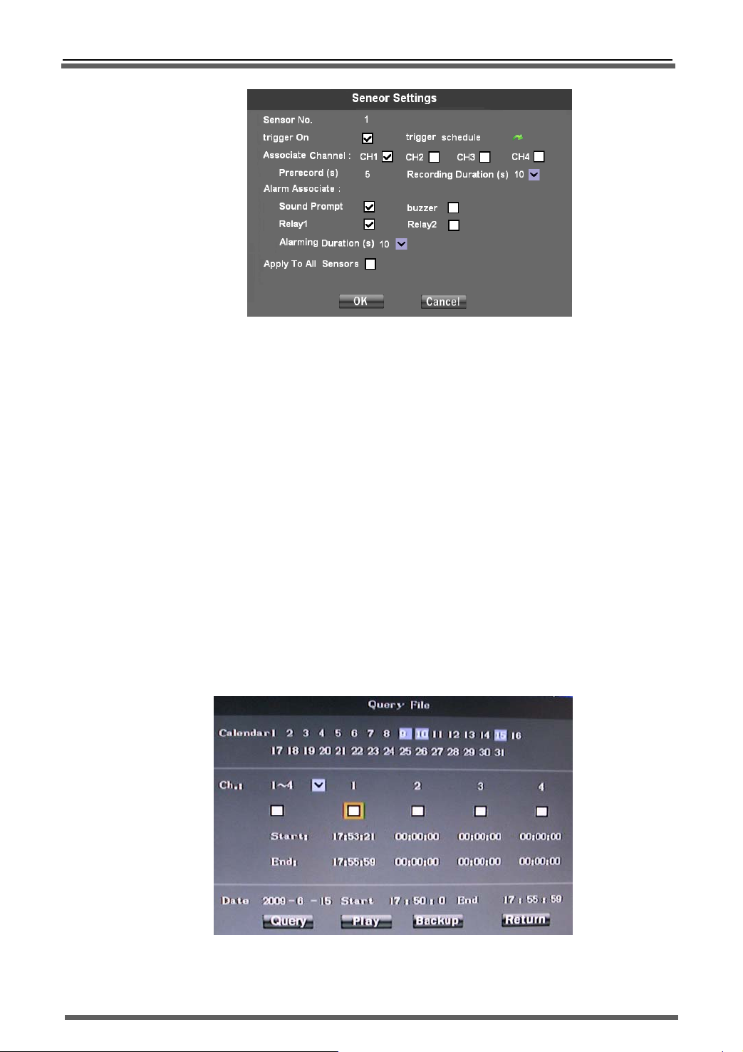
● Sensor:
Set sensor trigger time、associate alarm and associate recording channel etc. Setting interface as below
a) Sensor channel No.:select sensor input channel number(1~16)
b)
Trigger on:Unlock sensor trigger
c)
Trigger schedule:Set the trigger time periods
d)
Associate Channel:Set alarm trigger associate recording channel
>
Prerecord time:Set the prerecord time. After sensor triggered alarm, system will ahead of
“prerecord time” to start the recording
>
Recording duration:After sensor triggered alarm, systems will on-going record for the set
duration time.
e)
Alarm associate
>
Sound prompt:After triggered alarm, system will output “du…du …”warning tone.
>
Buzzer:After triggered alarm,the buzzer on the machine will output “Di ...Di... Di” warning
>
Relay:After triggered alarm,system will close the switch of relay to connect the outer alarm
>
Alarming Duration:Set the alarm duration. After triggered alarm, system will output the alarm
signal till you clean it by manual or the end of pre-setting alarm duration.
f)
Apply to all channel: Apply this channel sensor parameter settings to all channels.
tone.
system.
23
Page 25
>>Stand-alone DVR User Manual
Pic.27 Sensor Setting
3.6.5 File Management
Manage the recording files,can search, playback and backup the recording files based on the
given search condition. Search conditions include channel No., Date type, Record type, Recording
date and search periods. Interface as below: Left is date column, the blue background of the date on
behalf of the day that has recording files.
1) Recording Search:
Input Search channel No., Recording date and search time period. Press “Search”,It will show the
time period which has the recording file in “Start time”、“End time” under the each chosen channels.
2) Playback:As above, input the search condition,press “Search” to play the eligible
3) Video files. System support 8 ch playback at the same time(Means you can choose any
8CH at the most).
4) Backup:As above, input the search condition,press “Backup” to copy the eligible
video files to pointed device. Backup device selection interface as Pic.29:
Pic.28 Recording Files Management
24
Page 26
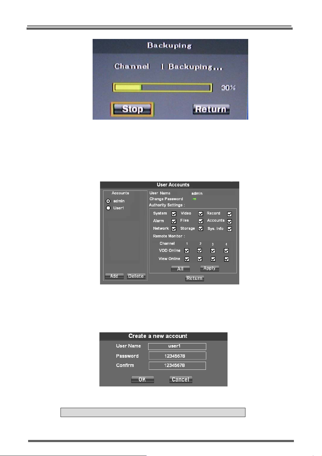
In operation interface, you can choose “play” or “Backup” this file to pointed device.
3.6.6 User Management
Create the user account, modify the user’s access, change password etc. Setting interface as
below:
1) Add/Delete user account:
System can manage 8 local accounts. Admin is default administrator account which can not be deleted.
Press “Add” button to pop-up user account create dialog box. As Below:
>>Stand-alone DVR User Manual
Pic.29 Video file backup
Pic.30 User management
Pic.31 Create a new account
Input user name and password, press “ok” to finish the creation.
NOTE:The maximum length of User name and password is 16 characters!
25
Page 27
>>Stand-alone DVR User Manual
2) Change password:
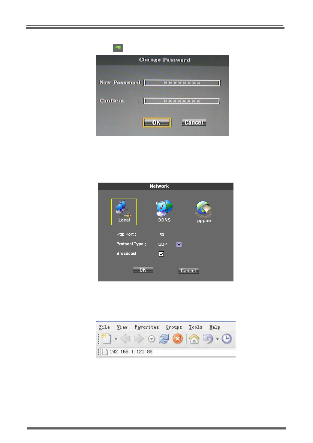
Press change password “ ” to popup the changing password dialog box, as below:
3) Authority settings:
3.6.7 NET SET
System support LAN、DDNS and PPPOE. Setting interface as below:
1) HTTP port set:Set HTTP port, default is 80, If this port changed, when login the host via Web server
(IE),The IP address input method is IP add “:”and new port number. For example:(192.168.1.121:88):
Pic.32:Change password
Charge user’s privilege and press “MODIFY” to confirm it.
Pic.33 Network Setting
图 34 Web Server Login
2) Protocol Type:Net transport protocol can be “UDP” or “TCP”. Usually choose “UDP” in LAN and
choose “USE Multicast”; Choose “TCP” in WAN.
NOTE: In WAN, please close “USE Multicast”!
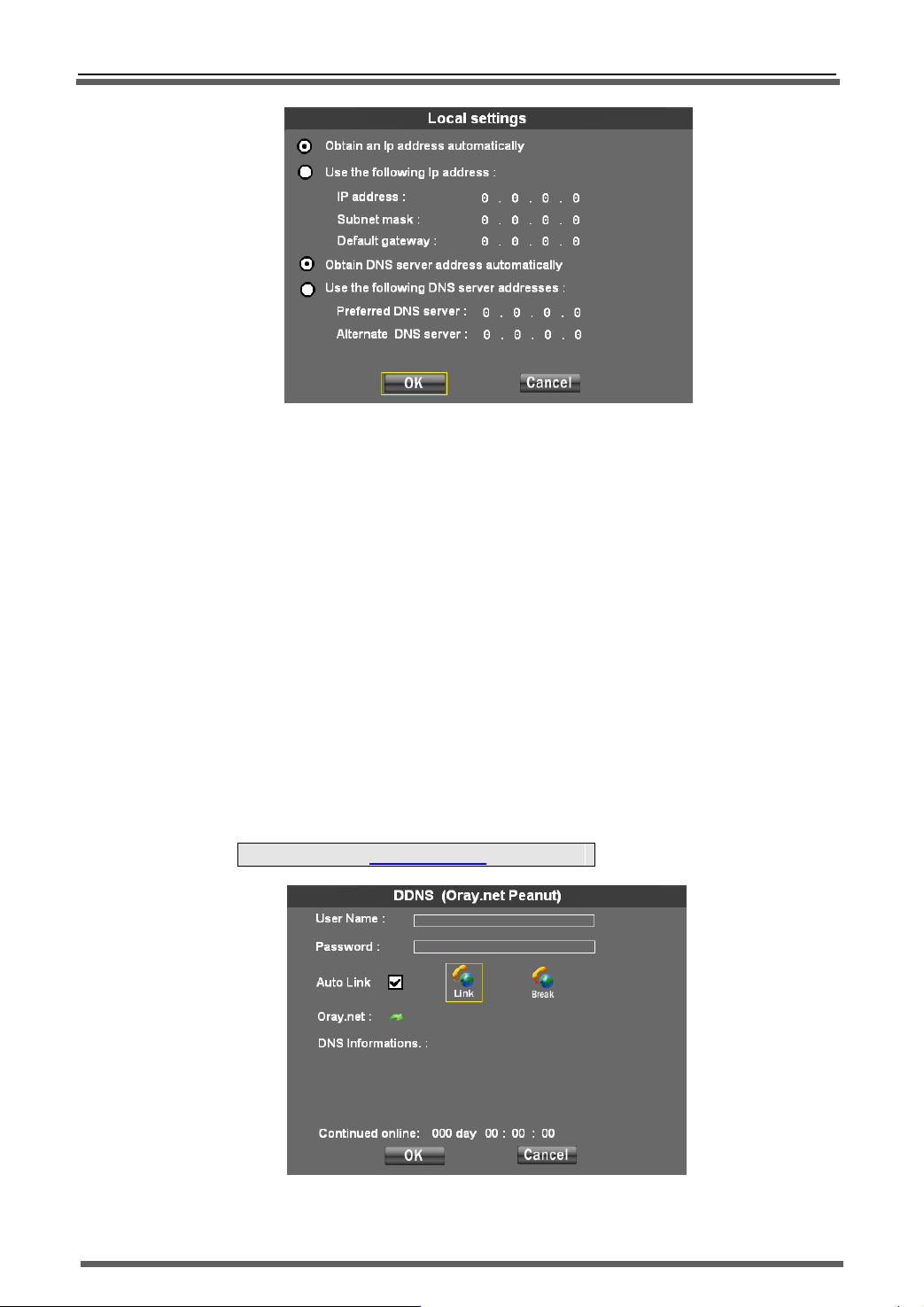
Local Connect setting:Local Connect setting also can set host IP, gateway and other clauses. You
3)
can choose “Obtain an IP automatically” or manual input IP. Setting interface as below:
26
Page 28
>>Stand-alone DVR User Manual
Pic.35 Local Setting
a) Obtain an IP automatically:
When connected network support DHCP IP(DHCP server open),when you choose “Obtain an
IP automatically”,DHCP server will allocate an available IP. System default setting is “Obtain an IP
automatically”.
Manual input IP:
b)
System input manual input IP. When choose “Use the following IP address”,IP address filed
will be editable, and you can input an IP address ,and then press “OK” to confirm it. DNS server can
set in same way.
DDNS setting:
System support DDNS setting. You need to apply an account from the DDNS server provider(Such as
Peanut passport:include account number, password and domain name,known as web site,for
example: videoweb.vicp.net),and then input the account information into “DDNS setting” column,
press “OK”, the system will connect the DDNS server automatically to apply DNS. The server will
analyze corresponding domain name to host actual IP address. When the user wants to login the DVR,
he only need to input the domain name in IE. Setting interface as below
:
Note:We only test the www.Oray.Net DNS server.
Pic.36 DDNS Setting
4)
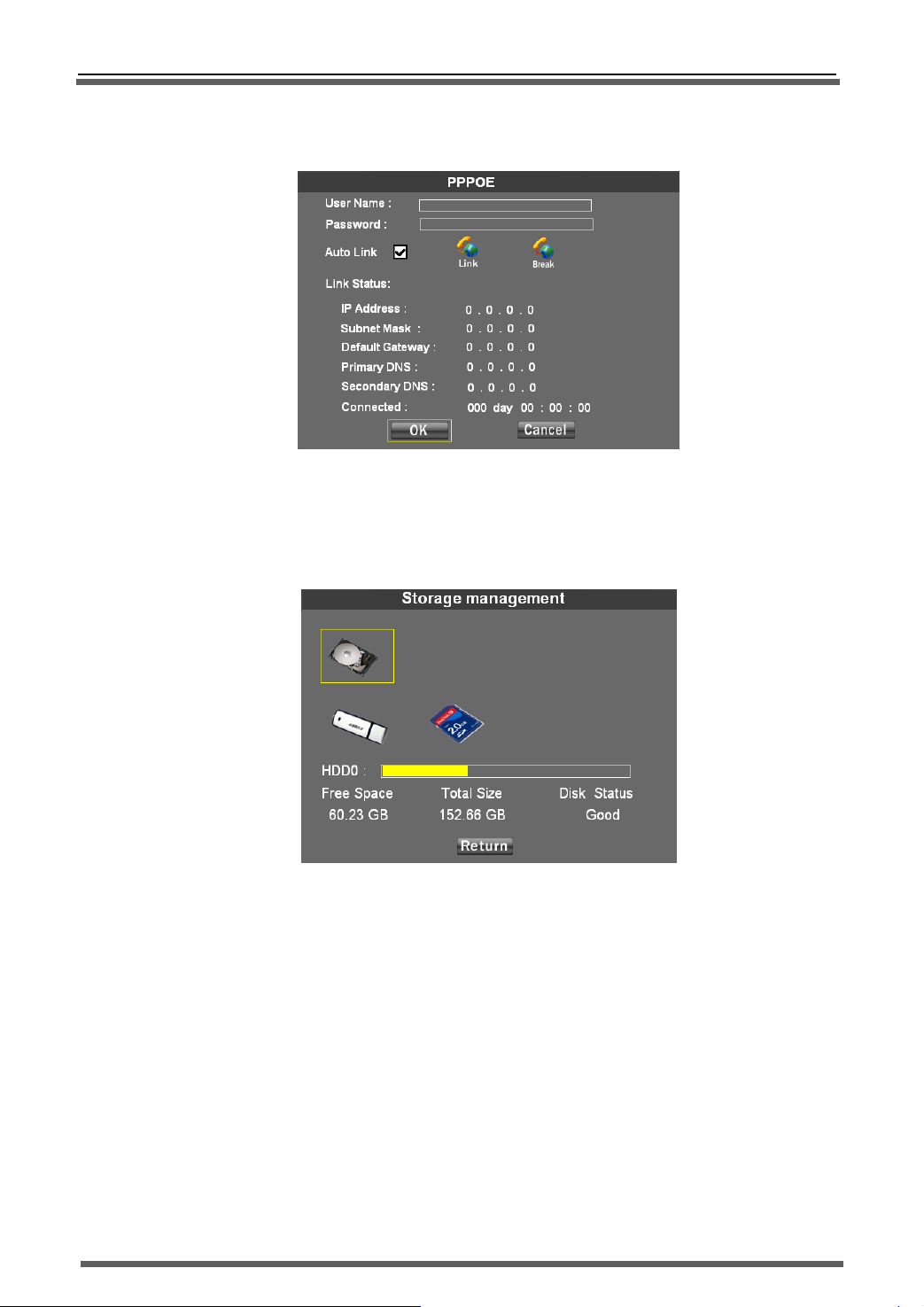
PPPOE setting:System support ADSL PPPOE dial connection directly. Connect the host with the
27
Page 29
>>Stand-alone DVR User Manual
ADSL model via RJ45 or LAN,it will dial automatically or by manual to connect the WAN .PPPOE setting
interface as below:
Pic.37 PPPOE Setting
3.6.8 Storage Management
Manage the storage device, display the device working condition, format and file selection.
Interface as below:
1) Device Info:Select and display the device information, as above:
Device Format:Select the device, press “Delete” button to format this device in FAT32 division
2)
format.
3)
File management:Press the device to enter “Stored File Info” list. In this list, you can choose the
recording file to play or choose upgrade file to update the system.
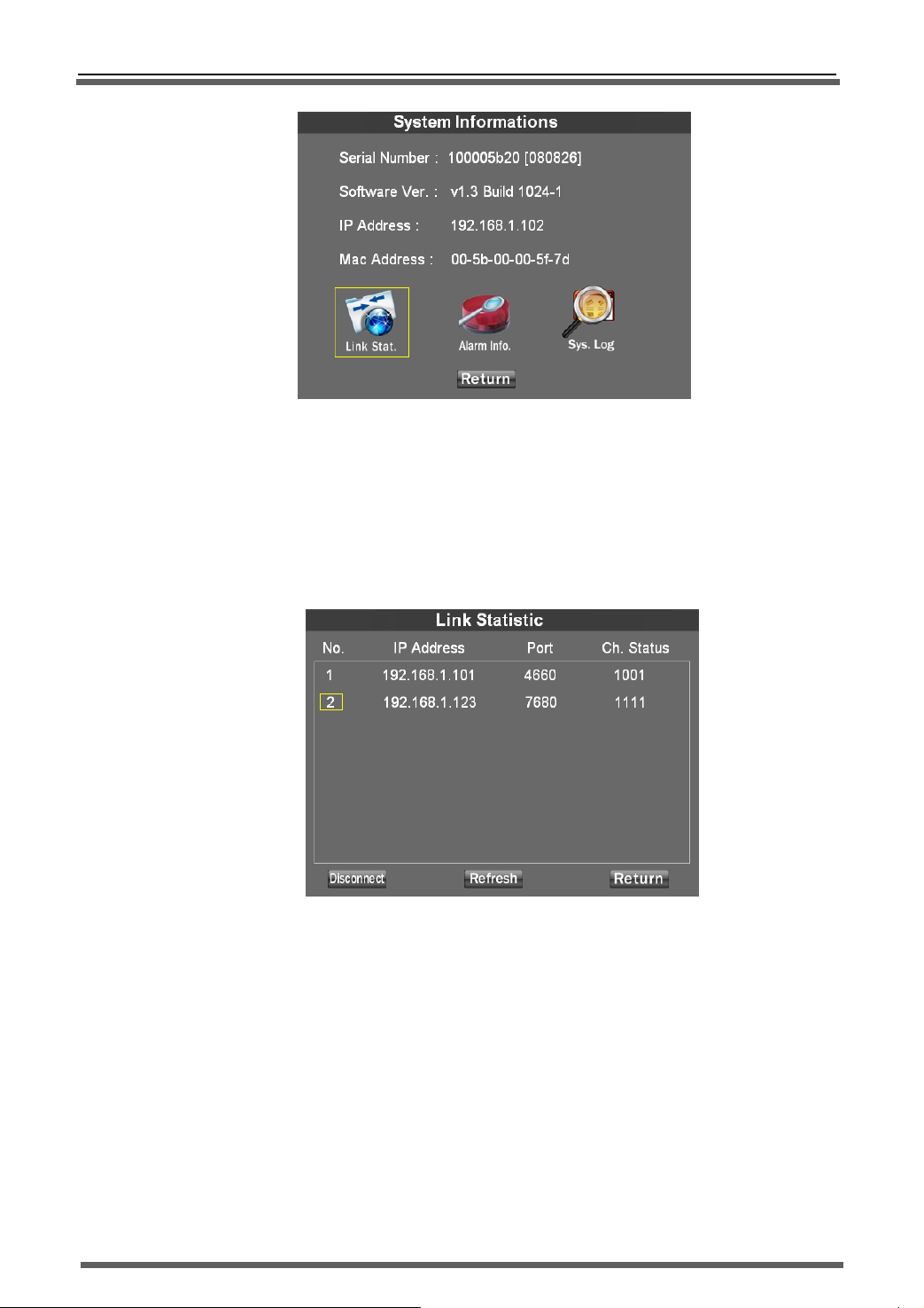
3.6.9 System Info
Enter system info dialog box to check the host “Serial Number”, “Software Version”, “IP
Address” and “MAC Address” etc.
Pic.38:Storage Management
28
Page 30
>>Stand-alone DVR User Manual
Pic.39:System Information
Host Information:
1)
Display the host serial No., software version, IP address and MAC address.
2) Link statistics:
Press “Link Stat.” to check the customer login information, and you can you can disconnect this IP
connection. As below:
Pic.40:Link Statistic
Above picture tell us the host is connected by two users. It also tells us the visitors IP, port No. and
remote monitoring status. Channel status is displayed in 4 figures: “0” means close and “1” means
open. The sequence is CH1-CH2-CH3-CH4. For example: 0101 means CH2 and CH4 are open and
CH1 and CH3 are close. Select the connection IP and press “Disconnect” to cut off this connection
。
Alarm information:
3)
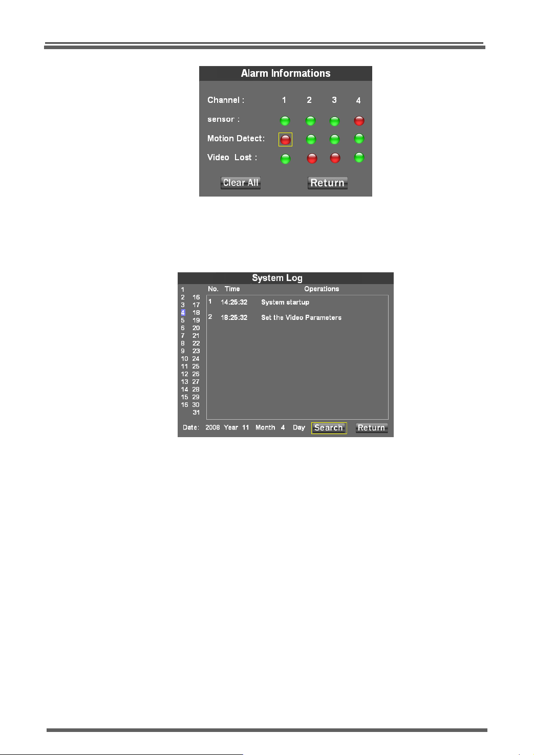
Check the system alarm status which is displayed into matrix form chart; junction shows the
incident triggered alarm types. Green color means no alarm and red color means alarm triggered.
When alarm triggered, you can press the triggered incidents to clean the alarm. As below
29
Page 31
>>Stand-alone DVR User Manual
Pic.41:Alarm information
4) System log:
Check the host operations recording. Input the date and press “SERACH” to list the
operation recording.
Pic.42:System Log
Left is date column, the blue background of the date on behalf of the day that has operation
recording
Chapter 4 WAN connection
There are two methods to connect the DVR with WAN: one is PPPoE and the other is router
forwarding.
4.1 PPPOE
Please check relevant chapter.
4.2 Router forwarding
1) Set the host IP
30
Page 32
>>Stand-alone DVR User Manual
Set the host IP in “Local setting”,please refer to the chapter “Net set”.
Note:Set the “protocol” in “TCP” when connecting the DVR with WAN.
2) Port forwarding
Login the router and mapping following port:
80:WEB port
9101:order transport port
9301:Support Video-on-demand
9501:Support multi channels live picture transport
9601:Support remote talkback
9801:Support multi hosts connection backup
3) DDNS (Oray.net)
Take oray software for example: first login the website www.oray.net
to apply user
account and domain name.
There are tow method to login DVR via Oray domain name: One is setting the DDNS in host,
the other is setting the DDNS in router.
4)Remote login
Input the Domain name in IE browser, for example: http://dvrtest01.eicp.net:80
the surveillance window. You also can input the domain name in software to remote login the
host.
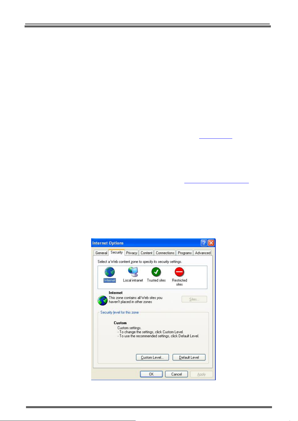
5)IE trusted site and security level setting
a) Open Internet Explorer and press “tool” - >“Internet options” to bob up the
following dialog box:
to open
31
Page 33
>>Stand-alone DVR User Manual
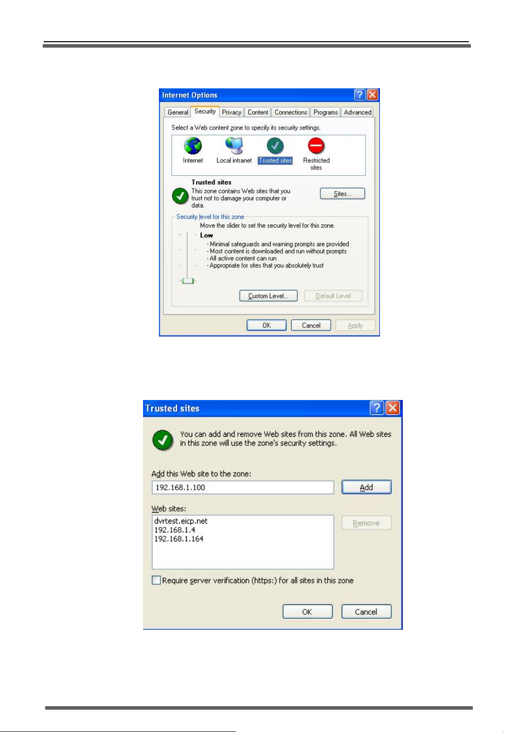
b) Press “Trusted sites” and “sites” in red box as follow to bob up the “trusted sites” dialog box:
c) Input the DVR IP, press “add” and “OK” to quit this dialog box.
v
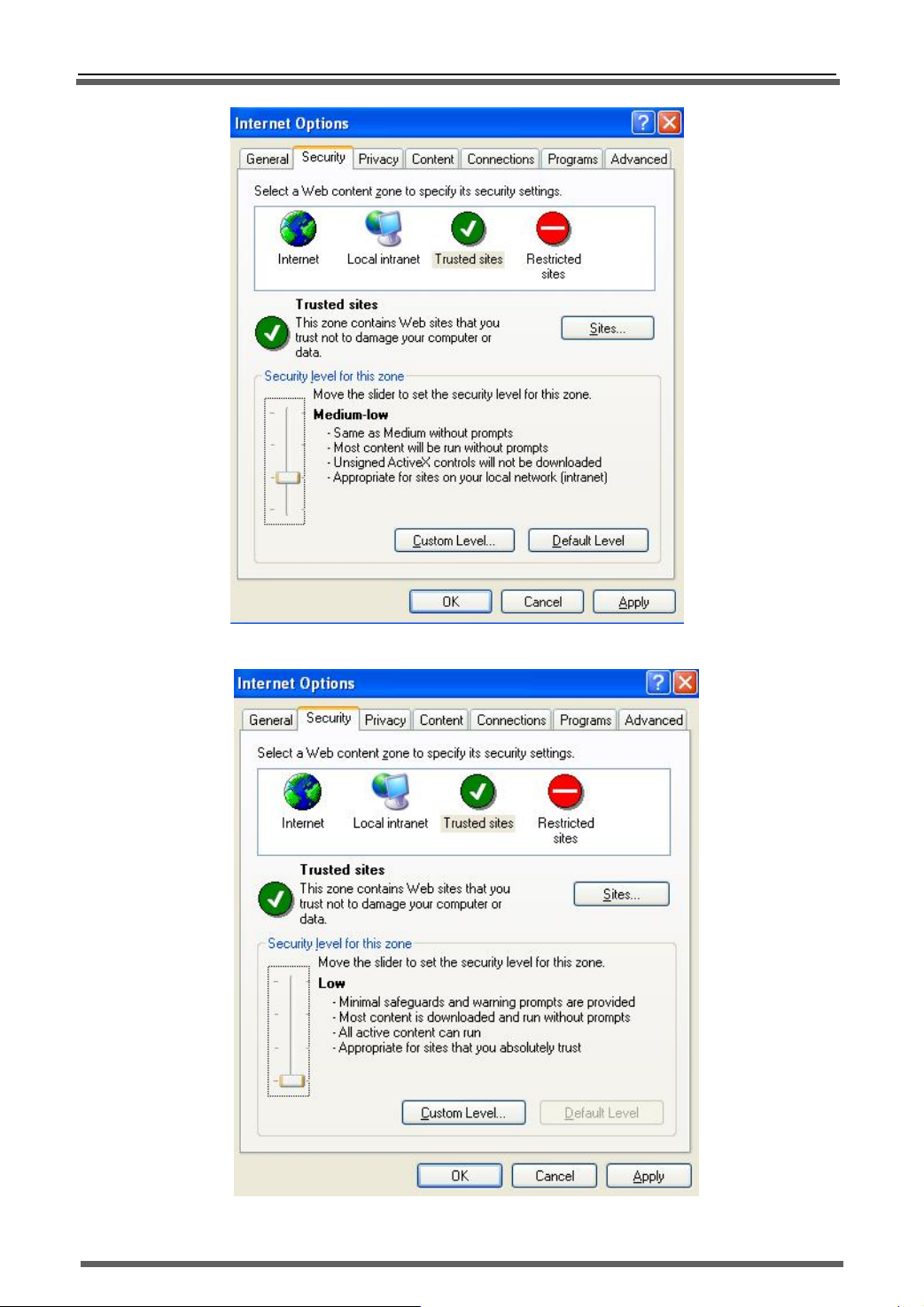
d) After abo
e setting, press “default level” to set the “security level” into “low” and then press
“Apply”.
32
Page 34
>>Stand-alone DVR User Manual
33
Page 35
>>Stand-alone DVR User Manual
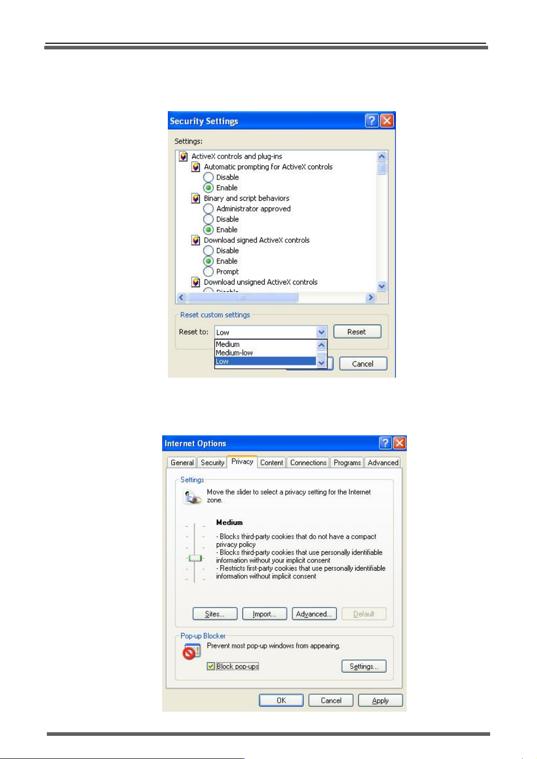
e) Or you can set the custom level: press “custom level” and enable all clauses under the “ActiveX
controls and plug-in” options.
f) In IE “Privacy” label, please cancel the “√” before the “Pop-up block” and then press “Apply”.
34
Page 36

 Loading...