


DVR User Manual
For LTD2504HE, LTD2508HE and
LTD2516HE
Version 1.0
Digital Video Recorder User Manual |
version 1.0 |
CAUTION
Please read this user manual carefully to ensure that you can use the device correctly and safely
We do not warrant all the content is correct. The contents of this manual are subject to change without notice
This device should be operated only from the type of power source indicated on the marking label. The voltage of the power must be verified before using. If not in use for a long time, pull out the plug from the socket
Do not install this device near any heat sources such as radiators, heat registers, stoves or other device that produce heat
Do not install this device near water. Clean only with a dry cloth
Do not block any ventilation openings. And ensure well ventilation around the machine
Do not power off the DVR at normal recording condition! The correct operation to shut off DVR is to stop recording firstly, and then select “shut-down” button at the right of the menu bar to exit, and finally to cut off the power.
This machine is indoor using equipment. Do not expose the machine in rain or moist environment. In case any solid or liquid get into the machine’s case, please cut off the power supply immediately, and ask for qualified technicians to check the machine before restart
Refer all servicing to qualified service personnel. No any parts repaired by yourself without technical aid or approval.
This manual is suitable for 4/8/16-channel digital video recorders. All examples and pictures used in the manual are from 16-channel DVR.
2

Digital Video Recorder User Manual version 1.0
|
|
|
Table of Contents |
1 |
Introduction........................................................................................................................................................................ |
5 |
|
|
1.1 |
DVR Introduction ........................................................................................................................................................................................................... |
5 |
|
1.2 |
Main Features................................................................................................................................................................................................................ |
5 |
2 |
Hardware Installation......................................................................................................................................................... |
6 |
|
|
2.1 Install Hard Drive &DVD Writer ..................................................................................................................................................................................... |
6 |
|
|
|
2.1.1 Install Hard Drive................................................................................................................................................................................................. |
6 |
|
|
2.1.2 Install DVD Writer................................................................................................................................................................................................ |
6 |
|
2.2 |
Front Panel Descriptions ............................................................................................................................................................................................... |
6 |
|
2.3 |
Rear Panel Instructions ................................................................................................................................................................................................. |
7 |
|
|
2.3.1 Rear Panel Interface ........................................................................................................................................................................................... |
7 |
|
2.4 |
Remote Controller.......................................................................................................................................................................................................... |
8 |
|
2.5 |
Control with Mouse........................................................................................................................................................................................................ |
9 |
|
|
2.5.1 Connect Mouse ................................................................................................................................................................................................... |
9 |
|
|
2.5.2 Use Mouse .......................................................................................................................................................................................................... |
9 |
3 |
Basic Function Instruction............................................................................................................................................... |
11 |
|
|
3.1 |
Power On/Off ............................................................................................................................................................................................................... |
11 |
|
|
3.1.1 Power on ........................................................................................................................................................................................................... |
11 |
|
|
3.1.2 Power off............................................................................................................................................................................................................ |
11 |
|
3.2 |
Login ............................................................................................................................................................................................................................ |
11 |
|
3.3 |
Live preview................................................................................................................................................................................................................. |
11 |
|
|
3.3.1 Live playback..................................................................................................................................................................................................... |
11 |
4 |
Main menu setup guide................................................................................................................................................... |
12 |
|
|
4.1 |
Basic configuration ...................................................................................................................................................................................................... |
12 |
|
|
4.1.1 System............................................................................................................................................................................................................... |
12 |
|
|
4.1.2 Time & date ....................................................................................................................................................................................................... |
13 |
|
|
4.1.3 DST.................................................................................................................................................................................................................... |
13 |
|
4.2 |
Live configuration......................................................................................................................................................................................................... |
14 |
|
|
4.2.1 Live .................................................................................................................................................................................................................... |
14 |
|
|
4.2.2 Host monitor ...................................................................................................................................................................................................... |
14 |
|
|
4.2.3 SPOT................................................................................................................................................................................................................. |
15 |
|
|
4.2.4 Mask .................................................................................................................................................................................................................. |
15 |
|
4.3 |
Record configuration ................................................................................................................................................................................................... |
15 |
|
|
4.3.1 Enable................................................................................................................................................................................................................ |
15 |
|
|
4.3.2 Record stream................................................................................................................................................................................................... |
16 |
|
|
4.3.3 Time................................................................................................................................................................................................................... |
16 |
|
|
4.3.4 Recycle record .................................................................................................................................................................................................. |
17 |
|
|
4.3.5 Stamp ................................................................................................................................................................................................................ |
17 |
|
4.4 |
Schedule configuration................................................................................................................................................................................................ |
17 |
|
|
4.4.1 Schedule............................................................................................................................................................................................................ |
17 |
|
|
4.4.2 Motion................................................................................................................................................................................................................ |
18 |
|
|
4.4.3 Sensor ............................................................................................................................................................................................................... |
18 |
|
4.5 Alarm configuration...................................................................................................................................................................................................... |
18 |
|
|
|
4.5.1 Sensor ............................................................................................................................................................................................................... |
18 |
|
|
4.5.2 Motion................................................................................................................................................................................................................ |
19 |
|
|
4.5.3 Video loss.......................................................................................................................................................................................................... |
20 |
|
|
4.5.4 Other alarm........................................................................................................................................................................................................ |
21 |
|
|
4.5.5 Alarm out ........................................................................................................................................................................................................... |
21 |
|
4.6 |
Network configuration.................................................................................................................................................................................................. |
21 |
|
|
4.6.1 Network ............................................................................................................................................................................................................. |
21 |
|
|
4.6.2 Network stream ................................................................................................................................................................................................. |
22 |
|
4.7 |
User management configuration................................................................................................................................................................................. |
23 |
|
4.8 |
P.T.Z configuration ....................................................................................................................................................................................................... |
24 |
|
4.9 Advanced ..................................................................................................................................................................................................................... |
26 |
|
|
|
4.9.1 Reset ................................................................................................................................................................................................................. |
26 |
|
|
4.9.2 Import/Export..................................................................................................................................................................................................... |
26 |
3
|
|
|
Digital Video Recorder User Manual |
version 1.0 |
|
|
|
4.9.3 Black/White list.................................................................................................................................................................................................. |
26 |
5 |
|
Record search & playback and backup ......................................................................................................................... |
27 |
|
|
5.1 Time search ................................................................................................................................................................................................................. |
27 |
||
|
5.2 |
Event search................................................................................................................................................................................................................ |
27 |
|
|
5.3 File management......................................................................................................................................................................................................... |
27 |
||
|
5.4 Backup......................................................................................................................................................................................................................... |
28 |
||
6 |
|
Manage DVR..................................................................................................................................................................... |
28 |
|
|
6.1 |
Check system information........................................................................................................................................................................................... |
28 |
|
|
|
|
6.1.1 System information............................................................................................................................................................................................ |
28 |
|
|
|
6.1.2 Event information .............................................................................................................................................................................................. |
28 |
|
|
|
6.1.3 Log information.................................................................................................................................................................................................. |
28 |
|
|
|
6.1.4 Network information .......................................................................................................................................................................................... |
29 |
|
|
|
6.1.5 Online information ............................................................................................................................................................................................. |
29 |
|
6.2 |
Manual alarm............................................................................................................................................................................................................... |
29 |
|
|
6.3 Disk management........................................................................................................................................................................................................ |
29 |
||
|
6.4 Upgrade ....................................................................................................................................................................................................................... |
29 |
||
|
6.5 |
Logoff ........................................................................................................................................................................................................................... |
29 |
|
7 |
|
Remote Surveillance........................................................................................................................................................ |
30 |
|
|
7.1 Accessing DVR............................................................................................................................................................................................................ |
30 |
||
|
|
|
7.1.1 On LAN.............................................................................................................................................................................................................. |
30 |
|
|
|
7.1.2 On WAN............................................................................................................................................................................................................. |
30 |
|
7.2 |
The remote live preview interface as below:............................................................................................................................................................... |
31 |
|
|
7.3 Remote playback & backup......................................................................................................................................................................................... |
33 |
||
|
|
|
7.3.1 Remote playback............................................................................................................................................................................................... |
33 |
|
|
|
7.3.2 Remote backup ................................................................................................................................................................................................. |
35 |
|
7.4 |
Remote System configuration ..................................................................................................................................................................................... |
35 |
|
8 |
|
Mobile Surveillance ......................................................................................................................................................... |
37 |
|
|
8.1 By Phones with Windows mobile ................................................................................................................................................................................ |
37 |
||
|
8.2 By Phones with Symbian............................................................................................................................................................................................. |
38 |
||
|
8.3 |
The Software installation for iPhone mobile clients .................................................................................................................................................... |
39 |
|
|
8.4 |
The installation & operation methods for Android mobile clients................................................................................................................................ |
46 |
|
|
8.5 Installation and operation Methods for BlackBerry Mobile phone Client.................................................................................................................... |
53 |
||
|
|
|
8.5.1 Installation instruction for BlackBerry Mobile phone Client.............................................................................................................................. |
53 |
|
|
|
8.5.2 Operation method for Blackberry mobile phone client..................................................................................................................................... |
55 |
Appendix A FAQ==============================================..100
Appendix B Calculate Recording Capacity==================================..106
Appendix C Compatible Devices=======================================.107
Appendix D 4-CH DVR Specifications=====================================108
Appendix E 8-CH DVR Specifications=====================================109
Appendix F 16-CH DVR Specifications====================================..110
4
Digital Video Recorder User Manual |
version 1.0 |
1 Introduction
1.1 DVR Introduction
This model DVR (Digital Video Recorder) is designed specially for CCTV system. It adopts high performance video processing chips and embedded Linux system. Meanwhile, it utilizes many most advanced technologies, such as standard H.264 with low bit rate, Dual stream, SATA interface, VGA output mouse supported, IE browser supported with full remote control, mobile view(by phones), etc., which ensure its powerful functions and high stability. Due to these distinctive characteristics, it is widely used in banks, telecommunication, transportation, factories, warehouse, and irrigation and so on.
1.2 Main Features
COMPRESSION FORMAT
•Standard H.264 compression with low bit rate and better image quality
LIVE SURVEILLANCE
•Support HD VGA output
•Support channel security by hiding live display
•Display the local record state and basic information
•Support USB to make full control
RECORD MEDIA
•Support two SATA HDD to record for a longer time without any limitation
BACKUP
•Support USB 2.0 devices to backup
•Support built-in SATA DVD writer to backup
•Support saving recorded files with AVI standard format to a remote computer through internet
RECORD & PLAYBACK
•Record modes: Manual, Schedule, Motion detection and Sensor alarm recording
•Support recycle after HDD full
•Resolution, frame rate and picture quality are adjustable
•128MB for every video file packaging
•4 audio channels available
•Two record search mode: time search and event search
•Support 1/4/9/16 screen playback simultaneously
•Support deleting and locking the recorded files one by one
•Support remote playback in Network Client through LAN or internet
ALARM
•1 channel alarm output and 4/8/16 channel alarm input available
•Support schedule for motion detection and sensor alarm
•Support pre-recording and post recording
•Support linked channels recording once motion or alarm triggered on certain channel
•Support linked PTZ preset auto cruise and track of the corresponding channel
PTZ CONTROL
•Support various PTZ protocols
•Support 128 PTZ presets and 8 auto cruise tracks
•Support remote PTZ control through internet
SECURITY
•Customize user right: log search, system setup, two way audio, file management, disk management, remote login, live view, manual record, playback, PTZ control and remote live view
•Support 1 administrator and 15 users.
•Support event log recording and checking, events unlimited
NETWORK
•Support TCP/IP, DHCP, PPPoE, DDNS protocol
•Support IE browser to do remote view
•Support setup client connection amount
•Support dual stream. Network stream is adjustable independently to fit the network bandwidth and environment.
5

Digital Video Recorder User Manual |
version 1.0 |
•Support picture snap and color adjustment in remote live
•Support remote time and event search, and channel playback with picture snap
•Support remote PTZ control with preset and auto cruise
•Support remote full menu setup, changing all the DVR parameters remotely
•Support mobile surveillance by smart phones , symbian, WinCE, Iphone or Gphone, 3G network available
•Support CMS to manage multi devices on internet
2 Hardware Installation
 Notice: Check the unit and the accessories after getting the DVR.
Please disconnect the power before being connected to other devices. Don't hot plug in/out
2.1 Install Hard Drive &DVD Writer
2.1.1 Install Hard Drive
 Notice: 1. This series support 4-ch and 8-ch connect to two SATA hard drivers or one SATA hard driver plus one Writer; 16-ch connects three SATA hard drivers or two hard drivers plus one DVD Writer. Please use the hard drive the manufacturers recommend specially for security and safe field.
2. Please calculate HDD capacity according to the recording setting. Please refer to “Appendix B Calculate Recording Capacity”.
Step1: Unscrew and Open the top cover
Step2: Connect the power and data cables. Place the HDD onto the bottom case as below.
Fig 2.1 Connect HDD
Step3: Screw the HDD as below.
Note: For the convenience to install, please connect the power and data cables firstly, and then screw to fix.
Fig 2.2 Screw HDD
2.1.2 Install DVD Writer
 Notice: 1. The writers must be the compatible devices we recommend. Please refer to “Appendix C Compatible Devices”.
2. This device is only for backup.
Step1: Unscrew and Open the top cover.
Step2: Connect the power and data cables. Place the DVD writer onto the bottom case as below.
Fig 2.3 Connect the DVD Writer
Step3: Screw the DVD writer as below.
Fig 2.4 Screw the Writer
2.2 Front Panel Descriptions
Notice: The front panel descriptions are only for reference; please make the object as the standard.
Item |
Type |
Name |
Description |
|
|
|
|
6
|
|
|
|
|
|
Digital Video Recorder User Manual |
version 1.0 |
||||
|
|
|
|
|
|
|
|
|
|
|
|
|
Item |
|
|
Type |
|
Name |
|
|
|
Description |
|
|
|
|
|
|
|
|
|
|
|
|
|
|
|
|
|
|
|
Power |
|
Power indicator, when connection , the light is blue |
|
||
|
|
|
|
Work state |
|
HDD |
|
When HDD is writing and reading , the light is blue |
|
||
|
|
|
|
|
Net |
|
When access to network , the light is blue |
|
|||
|
1 |
|
|
indicator |
|
|
|
||||
|
|
|
|
Backup |
|
When backup files and data, the light is blue |
|
||||
|
|
|
|
|
|
|
|
||||
|
|
|
|
|
|
Play |
|
When playing video, the light is blue |
|
||
|
|
|
|
|
|
REC |
|
When recording, the light is blue |
|
||
|
|
|
|
|
|
MENU/+ |
1. |
Enter menu in live |
|
||
|
|
|
|
|
|
2. |
Increase the value in setup |
|
|||
|
|
|
|
|
|
|
|
|
|||
|
|
|
|
|
|
BACKUP/- |
1. |
Decrease the value in setup |
|
||
|
|
|
|
|
|
2. |
Enter backup mode in live |
|
|||
|
|
|
|
|
|
|
|
|
|||
|
|
|
|
|
|
RECORD/FOCUS |
1. |
Record manually |
|
||
|
|
|
|
|
|
|
2. FOCUS function enables at PTZ mode |
|
|||
|
|
|
|
|
|
|
|
|
|
||
|
|
|
|
|
|
REW/SPEED |
|
1. Rewind key |
|
||
|
|
|
|
Compound button |
|
|
2. SPEED function enables at PTZ mode |
|
|||
|
2 |
|
|
|
|
|
|
|
|||
|
|
|
|
|
SEARCH/ZOOM |
1. |
Enter search mode |
|
|||
|
|
|
|
|
|
|
|||||
|
|
|
|
|
|
|
2.ZOOM function enables at PTZ mode |
|
|||
|
|
|
|
|
|
|
|
|
|
||
|
|
|
|
|
|
PLAY /IRIS |
1. |
Enter play interface |
|
||
|
|
|
|
|
|
2. |
IRIS function enables at PTZ mode |
|
|||
|
|
|
|
|
|
|
|
|
|||
|
|
|
|
|
|
FF/ P.T.Z. |
1. |
Fast forward |
|
||
|
|
|
|
|
|
2. |
Enter PTZ mode in live |
|
|||
|
|
|
|
|
|
|
|
|
|||
|
|
|
|
|
|
STOP/ESC |
1. |
Quit play mode |
|
||
|
|
|
|
|
|
2. |
Exit the current interface or status |
|
|||
|
|
|
|
|
|
|
|
|
|||
|
3 |
|
|
Digital button |
1-9 |
|
|
Input number 1-9 or choose camera |
|
||
|
|
|
|
0/10+ |
|
|
Input number0, 10 and the above number together with other digital keys |
|
|||
|
|
|
|
|
|
|
|
||||
|
|
|
|
|
|
Direction button |
Change direction to select items |
|
|||
|
4 |
|
|
Input button |
|
Multi-screen |
|
Change screen display mode like1/4/9/16 channel |
|
||
|
|
|
|
|
|
|
|||||
|
|
|
|
|
|
Enter button |
|
Confirm selection |
|
||
|
5 |
|
|
IR receiver |
|
IR |
|
For remote controller |
|
||
|
6 |
|
|
USB |
|
USB port |
|
To connect external USB devices like USB flash, USB HDD for backup or |
|
||
|
|
|
|
|
|
update firmware; or connect to USB mouse |
|
||||
|
|
|
|
|
|
|
|
|
|
||
2.3 Rear Panel Instructions
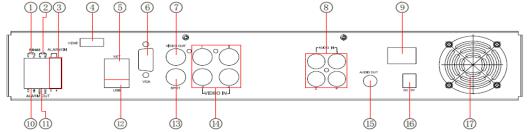
2.3.1 Rear Panel Interface
The rear Panel interface for 4-ch is shown as Fig 2.5:
|
|
|
|
|
|
Fig 2.5 Rear Panel for 4-ch |
Item |
|
|
Name |
|
|
Description |
1 |
|
|
P/Z |
|
|
Connect to speed dome |
2 |
|
|
K/B |
|
|
Connect to keyboard |
3 |
|
|
ALARM IN |
|
|
Connect to external sensor1-4 |
4 |
|
|
HDMI port |
|
|
Connect to high-definition display device (optional) |
5 |
|
|
NET |
|
|
Network port |
6 |
|
|
VGA port |
|
|
VGA output, connect to monitor |
7 |
|
|
Video out |
|
|
Connect to monitor |
8 |
|
|
Audio in |
|
|
4 CH Audio input |
9 |
|
|
POWER SWITCH |
|
|
Power on/off |
10 |
|
|
+ 5V and GND |
|
|
+5 V and Grounding |
11 |
|
|
ALARM OUT |
|
|
1-ch relay output. Connect to external alarm. |
12 |
|
|
USB port |
|
|
To connect external USB devices like USB flash, USB HDD for backup |
|
|
|
|
or update firmware; or connect to USB mouse |
||
|
|
|
|
|
|
|
13 |
|
|
Spot out |
|
|
Connect to monitor as an AUX output channel by channel. Only video |
|
|
|
|
display, no menu show |
||
|
|
|
|
|
|
|
14 |
|
|
Video in |
|
Video input channels from 1-4 |
|
15 |
|
|
Audio out |
|
Audio output, connect to the sound box |
|
16 |
|
|
POWER INPUT |
|
|
DC12V |
17 |
|
|
FAN |
|
|
For cooling the device |
|
|
|
|
Tab 2.1 Definitions of Front Panel Buttons |
||
The rear Panel interface for 8-ch is shown as Fig 2.6:
7

Digital Video Recorder User Manual |
version 1.0 |
|
|
|
|
|
Fig 2.6 Rear Panel for 8-ch |
Item |
|
|
Name |
|
Description |
1 |
|
|
P/Z |
|
Connect to speed dome |
2 |
|
|
K/B |
|
Connect to keyboard |
3 |
|
|
ALARM IN |
|
Connect to external sensor1-8 |
4 |
|
|
HDMI port |
|
Connect to high-definition display device (optional) |
5 |
|
|
NET |
|
Network port |
6 |
|
|
VGA port |
|
VGA output, connect to monitor |
7 |
|
|
Video out |
|
Connect to monitor |
8 |
|
|
Video in |
|
Video input channels from 1-8 |
9 |
|
|
Audio in |
|
4 CH Audio input |
10 |
|
|
POWER SWITCH |
|
Power on/off |
11 |
|
|
+ 5V and GND |
|
+5 V and Grounding |
12 |
|
|
ALARM OUT |
|
1-ch relay output. Connect to external alarm. |
13 |
|
|
USB port |
|
To connect external USB devices like USB flash, USB HDD for backup |
|
|
|
or update firmware; or connect to USB mouse |
||
|
|
|
|
|
|
14 |
|
|
Spot out |
|
Connect to monitor as an AUX output channel by channel. Only video |
|
|
|
display, no menu show |
||
|
|
|
|
|
|
15 |
|
|
Audio out |
|
Audio output, connect to the sound box |
16 |
|
|
POWER INPUT |
|
DC12V |
17 |
|
|
FAN |
|
For cooling the device |
|
|
|
|
Tab 2.2 Definitions of Front Panel Buttons |
|
The rear Panel interface for 16-ch is shown as Fig 2.7:
|
|
|
|
|
Fig 2.7 Rear Panel for 16-ch |
Item |
|
|
Name |
|
Description |
1 |
|
|
P/Z |
|
Connect to speed dome |
2 |
|
|
K/B |
|
Connect to keyboard |
3 |
|
|
ALARM IN |
|
Connect to external sensor1-16 |
4 |
|
|
HDMI port |
|
Connect to high-definition display device (optional) |
5 |
|
|
NET |
|
Network port |
6 |
|
|
VGA port |
|
VGA output, connect to monitor |
7 |
|
|
Video out |
|
Connect to monitor |
8 |
|
|
Video in |
|
Video input channels from 1-16 |
9 |
|
|
Audio in |
|
4 CH Audio input |
10 |
|
|
POWER SWITCH |
|
Power on/off |
11 |
|
|
FAN |
|
For cooling the device |
12 |
|
|
+ 5V and GND |
|
+5 V and Grounding |
13 |
|
|
ALARM OUT |
|
1-ch relay output. Connect to external alarm. |
14 |
|
|
USB port |
|
To connect external USB devices like USB flash, USB HDD for |
|
|
|
backup or update firmware; or connect to USB mouse |
||
|
|
|
|
|
|
15 |
|
|
Spot out |
|
Connect to monitor as an AUX output channel by channel. Only |
|
|
|
video display, no menu show |
||
|
|
|
|
|
|
16 |
|
|
Audio out |
Audio output, connect to the sound box |
|
17 |
|
|
POWER INPUT |
|
DC12V |
Tab 2.3 Definitions of Rear Panel Buttons
2.4 Remote Controller
It uses two AAA size batteries and works after loading batteries as following:
Step1: Open the battery cover of the Remote Controller
Step2: Place batteries. Please take care the poles (+ and -)
Step3: Replace the battery cover
 Notice: Frequently defect checking as following
1.Check batteries poles
2.Check the remaining charge in the batteries
3.Check IR controller sensor is mask
8
Digital Video Recorder User Manual |
version 1.0 |
If it still doesn't work, Please change a new remote controller to try, or contact your dealers
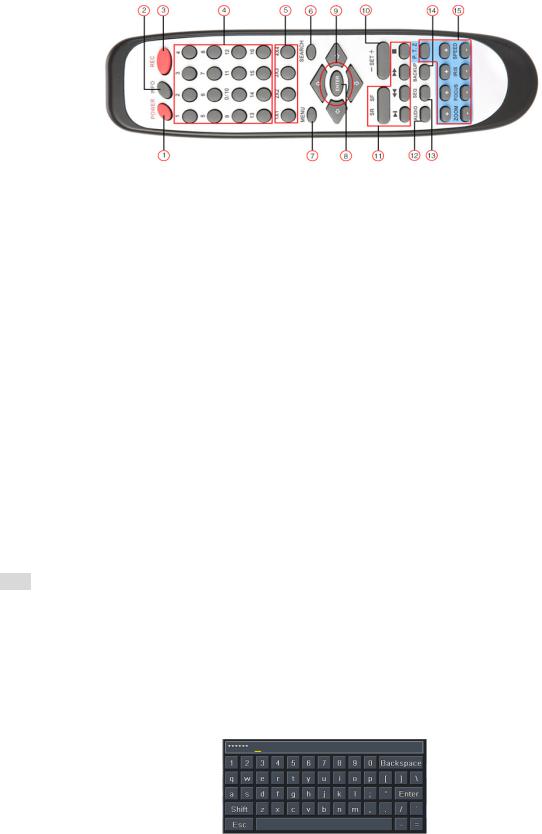
The interface of remote controller is shown in Fig2.8 Remote Controller.
|
|
|
|
|
Fig 2.8 Remote Controller |
Item |
|
|
Name |
|
Function |
1 |
|
|
Power Button |
|
Soft switch off to stop firmware running. Do it before power off. |
2 |
|
|
INFOR Button |
|
Get information about the DVR like firmware version, HDD information |
3 |
|
|
REC Button |
|
To record manually |
4 |
|
|
Digital Button |
|
Input digital or choose camera |
5 |
|
|
Multi Screen Button |
|
To choose multi screen display mode |
6 |
|
|
SEARCH Button |
|
To enter search mode |
7 |
|
|
MENU Button |
|
To enter menu |
8 |
|
|
ENTER Button |
|
To confirm the choice or setup |
9 |
|
|
Direction Button |
|
Move cursor in setup or pan/title PTZ |
10 |
|
|
+/- Button |
|
To increase or decrease the value in setup |
11 |
|
|
Playback Control Button |
To control playback, Fast forward/rewind/stop/single frame play |
|
12 |
|
|
AUDIO Button |
|
To enable audio output in live mode |
13 |
|
|
Auto Dwell Button |
|
To enter auto dwell mode |
14 |
|
|
BACKUP Button |
|
To enter backup mode |
15 |
|
|
PTZ Control Button |
|
To control PTZ camera: |
|
|
|
Move camera/ZOOM/FOCUS/IRIS/SPEED control |
||
|
|
|
|
|
|
Operation processes with remote controller to control multi-DVR
The device ID of the DVR is 0. When use of remote controller to control single DVR, it’s not necessarily to reset the device ID, user can do operation directly; when control multiple DVR with remote controller, please refer to below steps:
Step1: Activate remote controller to control DVR: enable DVR: turn the IR sensor of the remote controller to the IR receiver that on the front panel, press the number key 8 twice, then input device ID (Range from: 0-65535; the default device ID is 0.) with other digital number: 0-9, after that, press ENTER button to confirm.
Step2: User can check the device ID by enter into System configuration Basic configuration device ID. User also can set other DVR with the same device ID. For more convenient to operate, we don’t recommend user to set the device ID too long.
Step3: Cancel controller to control DVR: turn the IR sensor of the remote controller to the IR receiver that on the front panel, press the number key 8 twice, then input the device ID that needs to be cancelled from controlling, press ENTER button to confirm. After that, the DVR will not be controlled by remote controller.
2.5 Control with Mouse
2.5.1 Connect Mouse
It supports USB mouse through the ports on the rear panel, please refer to Fig 2.8 Remote Controller.
 Notice: If mouse is not detected or doesn't work, check below steps:
1.Make sure the mouse plugs in the USB mouse port not the USB port.
2.Change a mouse to try
2.5.2 Use Mouse
The structure of the main menu is shown in Fig 2.8 Remote Controller.
In live:
Double-click left button on one camera to be full screen display. Double-click again to return to the previous screen display.
Click right button to show the control bar at the bottom of the screen as Fig 2.8 Remote Controller. Here are all control and setup. Click right mouse again to hide the control bar.
In setup:
Click left button to enter. Click right button to cancel setup, or return to the previous.
If want to input the value, move cursor to the blank and click. An input window will appear as Fig2.9. It supports digitals, letters and symbols input.
Fig 2.9 Digital Numbers and Letters Input Window
Users can change some value by the wheel, such as time. Move cursor onto the value, and roll the wheel when the value blinks.
It supports mouse drag. I.e. Set motion detection area: click customized, hold left button and drag to set motion detection area. Set schedule: hold left button
9

Digital Video Recorder User Manual |
version 1.0 |
and drag to set schedule time.
In playback:
Click left button to choose the options. Click right button to return to live mode.
In backup:
Click left button to choose the options. Click right button to return to previous picture.
In PTZ control:
Click left button to choose the buttons to control the PTZ. Click right button to return to live.
Notice: Mouse is the default tool in all the operation below unless Exceptional indication.
10
Digital Video Recorder User Manual |
version 1.0 |
3Basic Function Instruction
3.1 Power On/Off
Before you power on the unit, please make sure all the connection is good.
3.1.1 Power on
Step1: connect with the source power; switch on the power button near the power port on the rear panel Step2: the device will be loaded, and the power indicator will display blue
Step3 before start, a WIZZARD window will be pop-up and show some information about time zone time setup network configuration, record configuration and disk management. User can setup here and refer to the concrete setup steps from the corresponding chapters. If users don’t want to setup Wizard, please click Exit button to exit.
After the device power on, if there is no menu or only has live image display, user can long press ESC button to switch.
Notice: this serial device can only display menu on VGA monitor or BNC monitor at one time, if there is live image display without menu display, please check up whether other device has menu display firstly, or long press ESC key to wait for login dialog box to appear. Long press ESC key can switch the output between BNC and VGA.
3.1.2 Power off
User can power off the device by using remote controller keyboard and mouse.
By remote controller:
Step1: press Power button, the Shut down window will appear, click OK, the unit will power off after a while.
Step2: disconnect the power
By keyboard and mouse:
Step1: enter into  Menu, then select “System Shut Down” icon, the Shut down window will appear
Step2: click OK, the unit will power off after a while.
Step3: disconnect the power
3.2 Login
User can login and logout the DVR system. User cannot do any other operations except changing the multi-screen display once logout.
Fig 3-1 Login
 Notice: the default user name and password is “admin” and 123456”
 The concrete operation steps for change password, add or delete user please refer to Fig 4.7 User management configuration for more details.
3.3 Live preview
|
|
Fig 3-2 live preview interface |
|
|
The explanation of symbol in the live preview interface: |
|
|
||
|
symbol |
meaning |
symbol |
meaning |
|
Green |
Manual record or time record |
Red |
Alarm record |
|
Yellow |
Motion detection record |
Figure icon |
Move event |
3.3.1 Live playback
Click Play  button to playback the record. Refer to Figure3-3. User can do concrete operation by click the buttons on screen.
11

Digital Video Recorder User Manual |
version 1.0 |
Fig 3-3 live playback
4Main menu setup guide
Click right mouse or press ESC button on the front panel, the control bar will display on the bottom of the screen, refer to Fig 4-1:
Fig 4-1 main menu toolbar
Click the  icon beside the screen display mode, a channel select dialog will appear as below:
Take 8-channel DVR for example: user can tick off 8 channels form 1-ch to 16-ch at random to display the live pictures. Then click  button to confirm the setting.
Click Menu  button, the interface will pop-up as Fig 4-2; press MENU button on the front panel or operate with remote controller also can display the main menu.
Fig 4-2 system setup
4.1 Basic configuration
Basic configuration includes three sub menus: system date& time and DST.
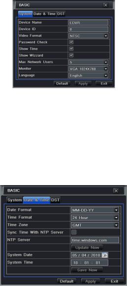
4.1.1 System
Step1: enter into system configuration basic configuration system; refer to Fig 4-3:
12
Digital Video Recorder User Manual |
version 1.0 |
Fig 4-3 basic configuration-basic
Step2: in this interface user can setup the device name, device ID, video format, max network users, VGA resolution and language. The definitions for every parameters display as below:
Device name: the name of the device. It may display on the client end or CMS that help user to recognize the device remotely. Video format: two modes: PAL and NTSC. User can select the video format according to that of camera.
Password check: enable this option, user needs to input user name and password can do corresponding operations with the relevant right in system configuration.
Show time: display time in live.
Show wizard: tick off this item, there will display an opening wizard with time zone and time setup information Max network uses: set the max user amount of network connection
VGA resolution: the resolution of live display interface, range from: VGA800*600 VGA1024*768 VGA1280*1024and CVBS
Note When switch between VGA and CVBS will change the menu output mode, please connect to relevant monitor.
Language: setup the menu language.
Note: after changed the language and video output, the device needs to login again.
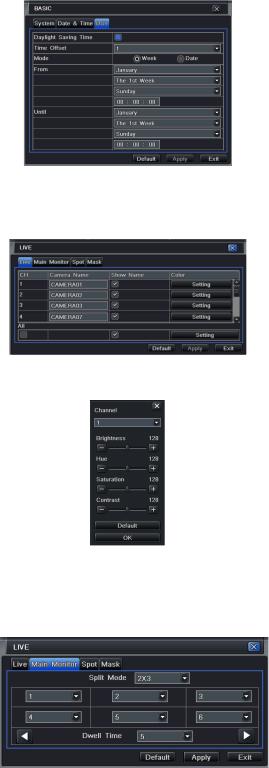
4.1.2 Time & date
Step1: enter into system configuration basic configuration time & date; refer to Fig 4-4:
Fig 4-4 basic configuration-time & date
Step2: set the date format, time format, time zone in this interface; tick off “sync time with NTP server” to refresh NTP server date; user also can adjust
system date manually
Step3: click “default” button to resort default setting; click “apply” button to save the setting; click “exit” button to exit current interface.
4.1.3 DST
Step1: enter into system configuration basic configuration DST; refer to Fig 4-5:
Step2: in this interface, enable daylight saving time, time offset, mode, start & end month/week/date, etc.
Step3: click “default” button to resort default setting; click “apply” button to save the setting; click “exit” button to exit current interface.
13
Digital Video Recorder User Manual |
version 1.0 |
Fig 4-5 basic configuration-DST
4.2 Live configuration
Live configuration includes four submenus: live, host monitor, SPOT and mask.
4.2.1 Live
In this interface, user can setup camera name, adjust colors: brightness, hue, saturation and contrast. Step1: enter into system configuration live configuration live; refer to Fig 4-6:
Fig 4-6 live configuration live
Note: Click Camera Name, a soft keyboard will pop up. User can self-define the camera name. Click Shift button, user can input Capital letters; click Shift button again, user can input Chinese characters.
Step2: tick off camera name; click “setting” button, a window will pop-up as Fig 4-7:
Fig 4-7 live-color adjustment
Step3: in this interface, user can adjust brightness, hue, saturation and contrast in live; click “default” button to resort default setting, click “OK” button to save the setting.
Step4: user can setup all channels with same parameters, tick off “all”, then do relevant setup.
Step5: click “default” button to resort default setting; click “apply” button to save the setting; click “exit” button to exit current interface.
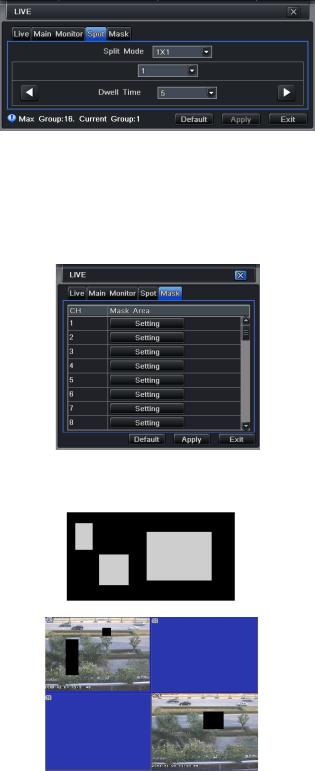
4.2.2 Host monitor
Step1: enter into system configuration live configuration host monitor; refer to Fig 4-8:
Fig 4-8 live configuration-host monitor
Step2: select split mode: 1×1 2×2 2×3 3×3 4×4 and channel
Step3: dwell time: the time interval for a certain dwell picture display switching to next dwell picture display
Step4: selected the split mode, then setup current picture group. Click  button to setup the previous channel groups of dwell picture, click
  button
to set the latter channel groups of dwell picture.
Step5: click “default” button to resort default setting; click “apply” button to save the setting; click “exit” button to exit current interface.
14
Digital Video Recorder User Manual |
version 1.0 |
4.2.3 SPOT
Step1: enter into system configuration live configuration SPOT; refer to Fig 4-9:
Fig 4-9 live configuration-SPOT
Step2: select split mode: 1×1and channel
Step3: dwell time: the time interval for a certain dwell picture display switching to next dwell picture display
Step4: selected the split mode, then setup current picture group. Click  button to setup the previous channel groups of dwell picture, click
  button to set the latter channel groups of dwell picture.
Step5: click “default” button to resort default setting; click “apply” button to save the setting; click “exit” button to exit current interface
4.2.4 Mask
User can setup private mask area on the live image picture, max threes areas.
Fig 4-10 live configuration-mask
Setup mask area: click Setting button, enter into live image to press left mouse and drag mouse to set mask area, refer to below picture. Click Apply button
to save the setting.
Delete mask area: select a certain mask area, click left mouse to delete that mask area, click Apply button to save the setting.
Setup mask area
Live image mask area
4.3 Record configuration
Record configuration includes five sub menus: enable, record bit rate, time, recycle record and stamp.
4.3.1 Enable
Step1: enter into system configuration record configuration enable; refer to Fig 4-11:
15

Digital Video Recorder User Manual |
version 1.0 |
Fig 4-11 record configuration-enable
Step2: tick off record, audio and record time
Step3: user can setup all channels with same parameters, tick off “all”, then to do relevant setup.
Step4: click “default” button to resort default setting; click “apply” button to save the setting; click “exit” button to exit current interface.
Definitions and descriptions of Record:
Parameter |
Meaning |
Record |
Record switch of every channels |
Audio |
Enable live record audio |
4.3.2 Record stream
Step1: enter into system configuration record configuration record bit rate; refer to Fig 4-12:
Fig 4-12 record configuration-record bit rate Step2: setup rate, resolution, quality, encode and max bit stream
Step3: user can setup all channels with same parameters, tick off “All”, then to do relevant setup.
Step4: click “default” button to resort default setting; click “apply” button to save the setting; click “exit” button to exit current interface.
Note: if the rate value set is over high the maximum resources of the device, the value will be adjusted automatically. Definitions and descriptions of Record stream:
Parameter |
Meaning |
Rate |
Range from: 1-30 NTSC 1-25(PAL) |
Resolution |
Support CIF and D1 |
Quality |
The quality of recorded images. The higher the value is, the clearer the recorded image |
|
is. Six options: lowest, lower, low, medium, higher and highest. |
Encode |
VBR and CBR |
Max bit stream |
Range from: 64 Kbps 128 Kbps 256 Kbps 512 Kbps 768 Kbps 1Mbps 2 Mbps |
4.3.3 Time
Step1: enter into system configuration record configuration time; refer to Fig 4-13:
16

Digital Video Recorder User Manual |
version 1.0 |
Fig 4-13 record configuration-time
Pre-alarm record time: the record time before event happen i.e. record time before motion detection or sensor alarm is triggered.
Post-alarm record: set the post recording time after the alarm is finished, five options: 10s 15s 20s 30s and 60s. Expire time: the hold time of saved records. If the set date is overdue, the record files will be deleted automatically. Step2: user can setup all channels with same parameters, tick off “all”, then to do relevant setup.
Step3: click “default” button to resort default setting; click “apply” button to save the setting; click “exit” button to exit current interface.
4.3.4 Recycle record
Step1: enter into system configuration record configuration recycle record;
Step2: tick off recycle record, the recycle record function will enable, it will cover the earlier recorded files and keep recoding when HDD is full; if disenable
this function, it will stop recording when HDD is full.
Step3: click “default” button to resort default setting; click “apply” button to save the setting; click “exit” button to exit current interface.
4.3.5 Stamp
Stamp User can overlap the channel name and time stamp on video.
Step1: enter into system configuration record configuration stamp; refer to Fig 4-14:
Fig 4-14 record configuration-stamp
Step2: tick off camera name, time stamp; click Set button, user can use cursor to drag the camera name and time stamp in random positions, refer to below Figures:
Before drag after drag
Step3: user can setup all channels with same parameters, tick off “all”, then to do relevant setup.
Step4: click “default” button to resort default setting; click “apply” button to save the setting; click “exit” button to exit current interface.
4.4 Schedule configuration
Schedule configuration includes three sub menus: schedule, motion and alarm.
4.4.1 Schedule
The volume means the seven days of a week from Monday to Sunday, the row means 24 hours of a day. Click the grid to do relevant setup. Blue means checked area, gray means unchecked area.
Step1: enter into system configuration schedule configuration schedule; refer to Fig 4-15:
17

Digital Video Recorder User Manual |
version 1.0 |
Fig 4-15 schedule configuration-schedule
Step2: select channel, double-click and a dialog box will pop-up as Fig 4-16, user can edit week schedule:
Fig 4-16 schedule-week schedule
Click “add” button to add a certain day schedule; click “delete” button to delete the selected schedule;
Copy: user can copy the specify schedule to other dates.
Click “OK” button to save the setting, click “Exit” button to exit current interface.
User can apply the schedule setting of certain channel to other or all channels, just only select channel and click “Copy” button. Step3: click “default” button to resort default setting; click “apply” button to save the setting; click “exit” button to exit current interface.
4.4.2 Motion
Step1: enter into system configuration schedule configuration motion; refer to Fig 4-17:
Fig 4-17 schedule configuration-motion Step2: the setup steps of motion are familiar with schedule; user can refer to 4.4.1 Schedule for details.
Note: the default schedule of motion detection is full-selected, that is, the color of schedule setting interface is blue.
4.4.3 Sensor
Step1: enter into system configuration schedule configuration alarm; refer to Fig 4-18:
Fig 4-18 schedule configuration-sensor
Step2: the setup steps of alarm are familiar with schedule; user can refer to 4.4.1 Schedule for details.
Note: the default schedule of sensor is full-selected, that is, the color of schedule setting interface is blue.
4.5 Alarm configuration
Alarm configuration includes five sub menus: sensor, motion, video loss, other alarm and alarm out.
4.5.1 Sensor
Sensor includes three sub menus: basic, alarm handling and schedule. Basic
Step1: enter into system configuration alarm configuration sensor basic; refer to Fig 4-19:
Step2: enable sensor alarm, set the alarm type according to triggered alarm type. Two option: NO and NC.
18

Digital Video Recorder User Manual |
version 1.0 |
Step3: user can setup all channels with same parameters, tick off “all”, then to do relevant setup.
Step4: click “default” button to resort default setting; click “apply” button to save the setting; click “exit” button to exit current interface.
Fig 4-19 alarm configuration-sensor-basic
Alarm handling
Step1: enter into system configuration alarm configuration sensor alarm handling; refer to Fig 4-20:
Fig 4-20 alarm configuration-sensor-alarm handling
Step2: select hold time, click Trigger button, and a dialog box will pop-up as Fig 4-21:
Fig 4-21 alarm handling-trigger Step3: tick off Buzzer, there will be triggered buzzer alarm out;
Full screen alarm: when triggered alarm, there will pop up full screen alarm;
To alarm out: tick off the channel, there will be triggered alarm out in the designated channel. Click OK button to save the setting; click Exit button to exit the current interface.
To record: tick off recoding channels, it will record the camera when alarm triggered. Click OK button to save the setting; click Exit button to exit the current interface.
To P.T.Z: set linked preset and cruise for alarm. User can select any channel and multi channels as linked channels. Click OK button to save the setting; click Exit button to exit the current interface.
Step4: user can setup all channels with same parameters, tick off “all”, then to do relevant setup.
Step5: click “default” button to resort default setting; click “apply” button to save the setting; click “exit” button to exit current interface. Schedule
Step1: enter into system configuration alarm configuration sensor schedule; refer to Fig 4-22:
Fig 4-22 sensor-schedule
Step2: the setup steps of sensor schedule are familiar with schedule; user can refer to 4.4.1 Schedule for details.
Note: the default schedule of sensor is full-selected, that is, the color of schedule setting interface is blue.
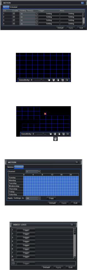
4.5.2 Motion
Motion includes two sub menus: motion and schedule. Motion
Step1: enter into system configuration alarm configuration motion; refer to Fig 4-23:
19
Digital Video Recorder User Manual |
version 1.0 |
Fig 4-23 alarm configuration-motion
Step2: enable motion alarm, set alarm hold time which means time interval between two adjacent detective motions. If there is other motion detected during the interval period which is considered continuous movement; otherwise, it will be considered that those two adjacent detective motions are two different motion events. Click Trigger button, a dialog box will pop-up:
Step3: the setup steps of motion trigger are familiar with alarm handling; user can refer to Chapter 4.5.1 Sensor alarm handling for more details. Step4: click Area button, a dialog box will pop-up as Fig 4-24:
Fig 4-24 motion-area
Step5: in the Area interface, user can drag slide bar to set the sensitivity value (1-8), the default value is 4. The higher the value is the higher sensitivity you get. Due to the sensitivity is influenced by color and time (day or night), user can adjust its value according to the practical conditions; click  icon, set the whole area as detection area; click
  icon, the set detection area will be cleared; click
  icon, user can test whether the sensitivity value and motion area are suitable accordingly refer to following picture ; Click
  icon, to save the setting; click
  icon, exit current interface.
Note: when user drag mouse to set motion detection area, they have to click |
icon to clear all set detection area firstly, and then make the |
operation. |
|
Step6: user can setup all channels with same parameters, tick off “all”, then to do relevant setup.
Step7: click “default” button to resort default setting; click “apply” button to save the setting; click “exit” button to exit current interface. Schedule
Step1: enter into system configuration alarm configuration schedule; refer to Fig 4-25:
Fig3-25 alarm configuration-schedule
Step2: the setup steps of alarm schedule are familiar with schedule; user can refer to 4.4.1 Schedule for details.
4.5.3 Video loss
Step1: enter into system configuration alarm configuration video loss; refer to Fig 4-26:
Fig 4-26 alarm configuration-video loss
Step2: the setup steps of video loss trigger are familiar with alarm handling; user can refer to Chapter 4.5.1 Sensor alarm handling for more details. Step3: user can setup all channels with same parameters, tick off “all”, then to do relevant setup.
Step4: click “default” button to resort default setting; click “apply” button to save the setting; click “exit” button to exit current interface.
20
Digital Video Recorder User Manual |
version 1.0 |
4.5.4 Other alarm
Step1: enter into system configuration other alarm; refer to Fig 4-27:
Fig4-27 other alarm
Step2: select a hard disk in the pull down list box, when the disk capacity is lower than that value, there will appear some text information on the lower right of the live image.
Step3: click “default” button to resort default setting; click “apply” button to save the setting; click “exit” button to exit current interface.
4.5.5 Alarm out
Alarm out includes three sub menus: alarm out, schedule and buzzer Alarm out
Step1: enter into system configuration alarm out; refer to Fig 4-28:
Fig 4-28 system configuration-alarm out
Step2: in this interface, set relay alarm out name, select hold time which means the interval time between the two adjacent alarms. Step3: user can setup all channels with same parameters, tick off “all”, then to do relevant setup.
Step4: click “default” button to resort default setting; click “apply” button to save the setting; click “exit” button to exit current interface. Schedule
Step1: enter into system configuration schedule;
Step2: the setup steps of alarm out schedule are familiar with schedule; user can refer to 4.4.1 Schedule for details.
Note: the default schedule of motion detection is full-selected, that is, the color of schedule setting interface is blue.
Buzzer
Step1: enter into system configuration buzzer; Step2: tick off Buzzer, set buzzer alarm hold time
4.6 Network configuration
Network configuration includes two submenus: network and network stream.
4.6.1 Network
Step1: enter into system configuration network configuration network; refer to Fig4-29:
Fig 4-29 network configuration-network
Step2: HTTP port: the default value is 80. If the value changed, user needs to add the port number when typing IP address in IE address blank .i.e. set
HTTP port to 82, IP address: http://192.168.0.25, user needs to input that address: http://192.168.0.25:82 into IE browser.
Server port: communication port
Step3: Tick off the "Obtain an IP address automatically", the device will distribute IP address, subnet mask, and gateway IP and DNS server.
Step4: enable PPPoE, user can directly connect the DVR to internet via ADSL, then input the user name and password; click TEST button to test the
effectiveness of the relevant information.
21
Digital Video Recorder User Manual |
version 1.0 |
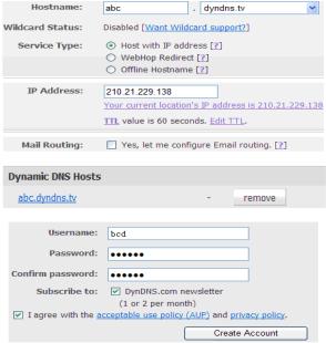
1 Domain name Registration Take www.dyndns.com for example
Note: Users can self-define the hostname, username and password.
Input www.dyndns.com in the IE address bar, user can access the domain name registration interface. Click “Sign up Free” and then select the first picture, click “Sign up” to register. For example: Hostname is “abc.dyndns.tv. The picture is shown as follows:
After user fill in the blank, click “Add to cart”, Dynamic DNS Hosts dialog box will be displayed.
Then create user account. For example, the username is “bcd”, password is “123456”.
Click” Create Account” button to create user account.
2 DVR Setting
1 Domain name
According to the domain name registration of “DDNS” the domain name for DVR is “www. abc.dyndns.tv”
2 Username and password
According to the above registration, username is “bcd”. According to the above registration, password is “123456”
3 Application
Connect DVR to the Network Client.
Enter into Basic configuration network other settings, tick off DDNS, and select “Dyndns” at the DDNS Sever pull down list box and input user name and password.
Enter into configuration interface of the router, map the server port and IP address. Click Save button to save the setting Login IE browser and input registered domain name “http://www.abc.dyndns.tv”, connect to DVR client.
Note: If the value changed, user needs to add the port number when typing IP address in IE address blank .i.e. set HTTP port to 82, IP address: http://192.168.0.25, user needs to input that address: http://192.168.0.25:82 into IE browser.
Definitions and descriptions of network configuration:
Parameter |
Meaning |
HTTP port |
The port number of accessing IE browser. The default port is 80 |
Server port |
The port number of data. The default port is 6036 |
|
Static IP |
IP address |
The IP address of the server |
Subnet mask |
The subnet mask of the server |
Gateway |
The gateway of the server |
DNS server |
The address of DNS server |
|
PPPoE |
User name |
User name of broad band dial-up |
Password |
Password of broad band dial-up |
|
DDNS server |
DDNS server |
Website provided by dynamic domain name supplier. The optional: |
|
www.dns2p.net www.meibu.com www.dyndns.comandwww.no-ip.com |
|
|
User name |
User name for log in the website of domain name supplier |
Password |
Password for log in the website of domain name supplier |
4.6.2 Network stream
Step1: enter into system configuration network configuration sub stream; refer to Fig 4-30:
22
 Loading...