

Page 1

Table of Contents
Basic NVR Setup ............................................. 2
Web Client Setup ........................................... 3
Install/Update Plugin ................................. 3
Install the Plugin on a Mac ......................... 4
Port Forwarding ......................................... 7
Port Fwd. Ex. 1 (Newer Linksys) ............. 8
Port Fwd. Ex. 2 (Older Linksys) ............... 9
DDNS Registration and Setup .................. 10
Basic Usage .................................................. 12
View Cameras .......................................... 12
Playback ................................................... 12
Download Video ....................................... 13
Log Search ................................................ 13
Configuration ............................................... 14
File Download Location............................ 14
Video Stream Quality ............................... 14
Camera Names ......................................... 15
Video Quality ........................................... 15
Schedule ................................................... 16
Motion Detection Fine Tuning ................. 16
E-mail Alerts Setup ................................... 17
Firmware Version/Upgrade/Downgrade . 18
Reboot/Restore/Default .......................... 19
IP Camera Web Client .................................. 20
Accessing the IP Camera .......................... 20
Basic Usage .............................................. 22
Snapshot/Clip Locations .......................... 22
Firmware Version/Upgrade/Downgrade . 23
Reboot/Restore/Default .......................... 24
Image & Audio Settings ........................... 24
Troubleshooting ........................................... 27
Limitations.................................................... 28
Step 1: Connect the NVR to the Network
Make sure the NVR is connected to the local
network with an Ethernet cable.
Step 2: Get the IP Address
This is how the NVR is accessed from a computer
via a web browser. It is a good idea to write the
IP address down. Be sure to get IP address from
the Maintenance section:
Menu > Maintenance >
System Info > Network
Step 3: Go to the IP Address
Type the IP address of the NVR into a web
browser (IE, Chrome, Firefox, and Safari).
Platinum Web Client Guide
Default Username: admin
Default Password: 12345
Default Ports: 80 (web/HTTP)
8000 (server/app)
8554 (video/RTSP)
DDNS Site: http://ns1.dvrlists.com
Video Player: Platinum Player
IP Scanner: SADP
Mac Plugin: Mac Web Component
Firmware & Tools: Platinum Downloads
http://www.ltsecurityinc.com/ Menu 1 | P a g e
Page 2
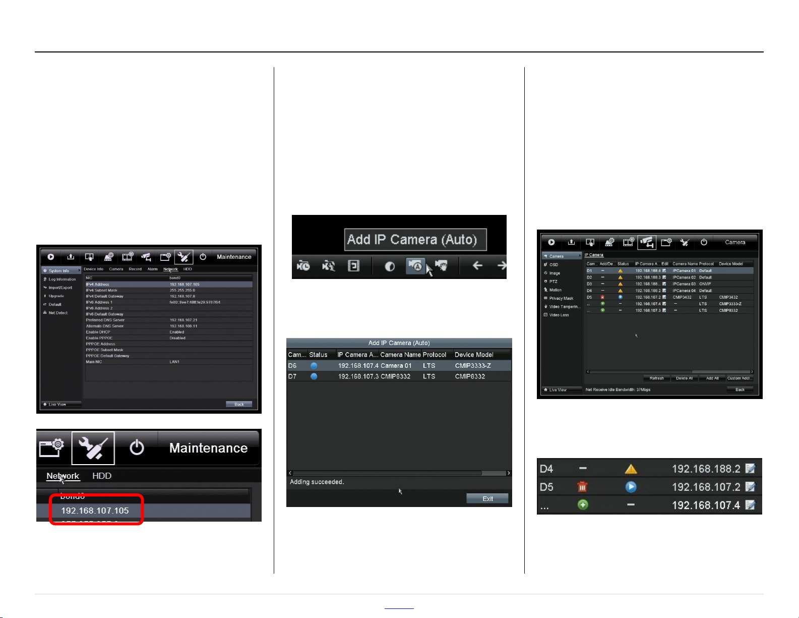
Getting the IP Address
Be sure to get the NVR online and configured
before using the web client. The NVRs now
have DHCP turned on by default since
firmware version 140404 (2014 April 4th).
Go to:
Menu > Maintenance >
System Info > Network
Basic NVR Setup
Quickly Adding the Cameras
Cameras connected to the built-in PoE switch
are added automatically. Cameras connected
to an external PoE switch are still easy to
add. The fastest way to add these cameras is
from the main tool bar.
Click: “Add IP Camera (Auto)”
All cameras connected to the External PoE
switch will be given IP numbers and added.
Arranging Cameras (optional)
There are actually two way to arrange
cameras, but only one will affect the web
client. Initially, cameras (on an external PoE
switch) are arranged in the order they are
added. The cameras can be removed and
added back:
Menu > Camera > Camera
The NVR’s IP Address
http://www.ltsecurityinc.com/ Menu 2 | P a g e
Trash Can = delete Triangle (!) = error
Circle (+) = add Circle () = play
For the NVR monitor (only) way:
Menu > Configure > Live View > View
Page 3
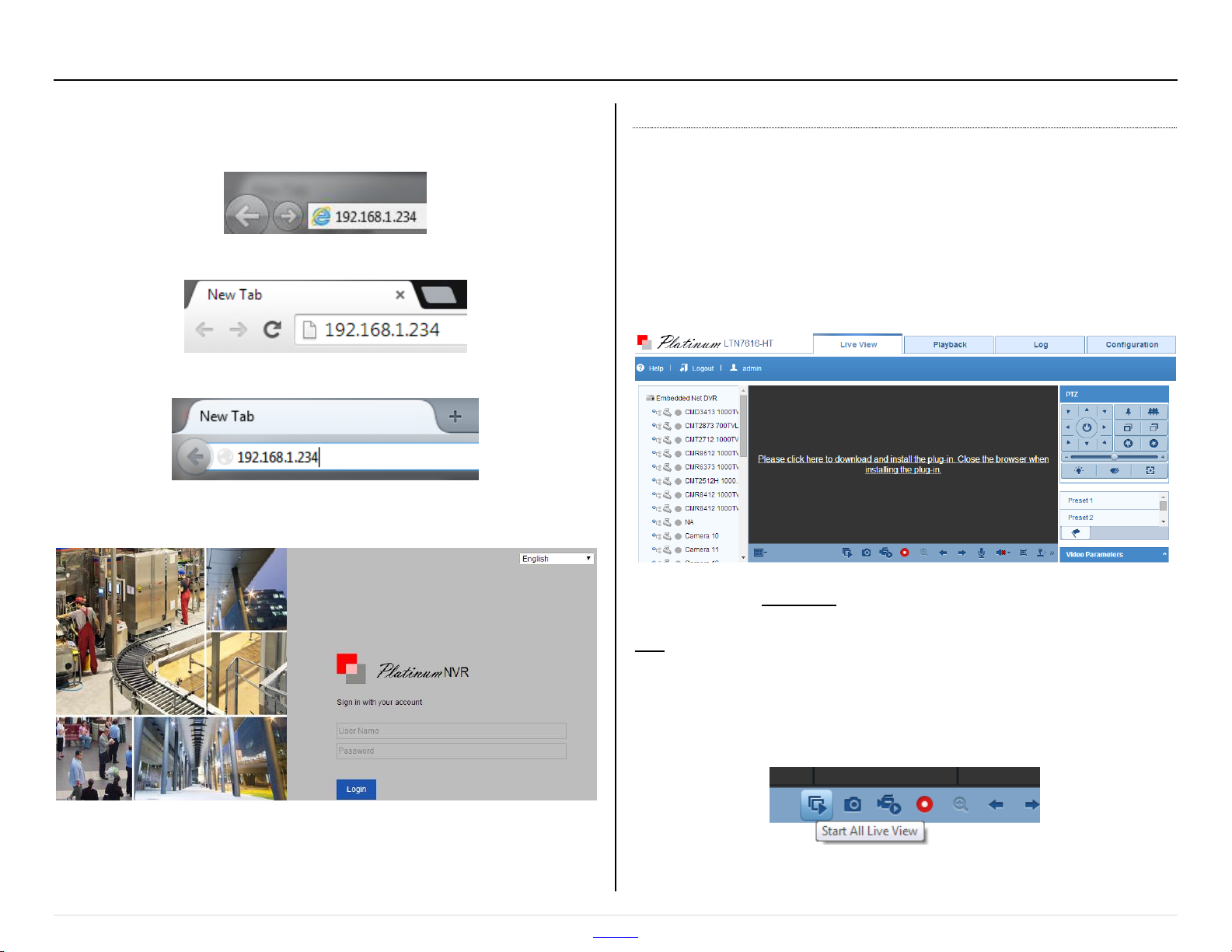
Web Client Setup
Once you have the IP address of the NVR, type it into a web browser.
Internet Explorer (Microsoft)
Chrome (Google)
Firefox (Mozilla)
Then a login screen should appear:
Install/Update Plugin
The web client will then ask you to install a plugin:
“Please click here to download and install the plug-in. Close the
browser when installing the plug-in.”
(The second part only applies to updating the plugin. First time
installations can leave the browser running.)
Click that link to download the plugin installer.
Run that installer to actually install the plugin.
For IE and Chrome, refresh the page to use the plugin. If that fails, or if
Firefox is used, then quit and reopen the program. For plugin
upgrades, be sure the browser is closed.
Enter the username and password and click [Login].
Defaults: username = admin
password = 12345
http://www.ltsecurityinc.com/ Menu 3 | P a g e
Click “Start All Live View” to show the cameras.
Page 4
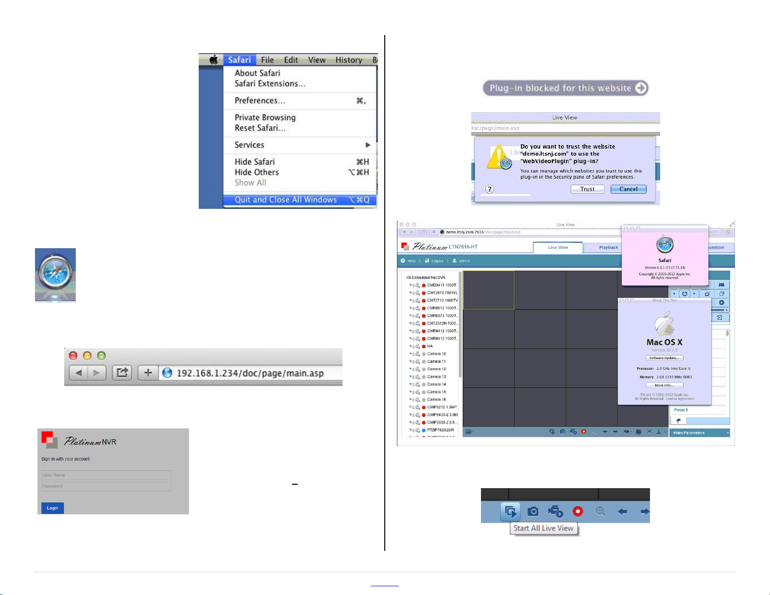
Install the Plugin on a Mac
Installing the web component on a Mac can be disorienting for a
Windows user. There are some differences.
Here is an outline of the steps to follow:
1. Check the Mac/Safari Version
2. Download the Plugin Installer for Mac
3. Enable “Anywhere” Program Installation
4. Run the Plugin Installer
5. Disable “Anywhere” Program Installation
6. Quit Safari
7. Open Safari
8. Enter the NVR's IP address
9. Login to the NVR
10. Allow the Plugin
11. Turn on the Cameras
Step 1: Check the Mac/Safari Version
Mac OS X version 10.9.x and up recommended. Safari 6.x and up
recommended. Please keep your browser up-to-date for security.
In tests, the web component was used with Mac OS X version 10.7.5
and Safari version 6.1.1 (on a Mac Mini).
Step 2: Download the Plugin Installer for Mac
You can download the plugin directly, or find it at the bottom of the
Platinum Download page. It will be called: “Web Component for Mac”
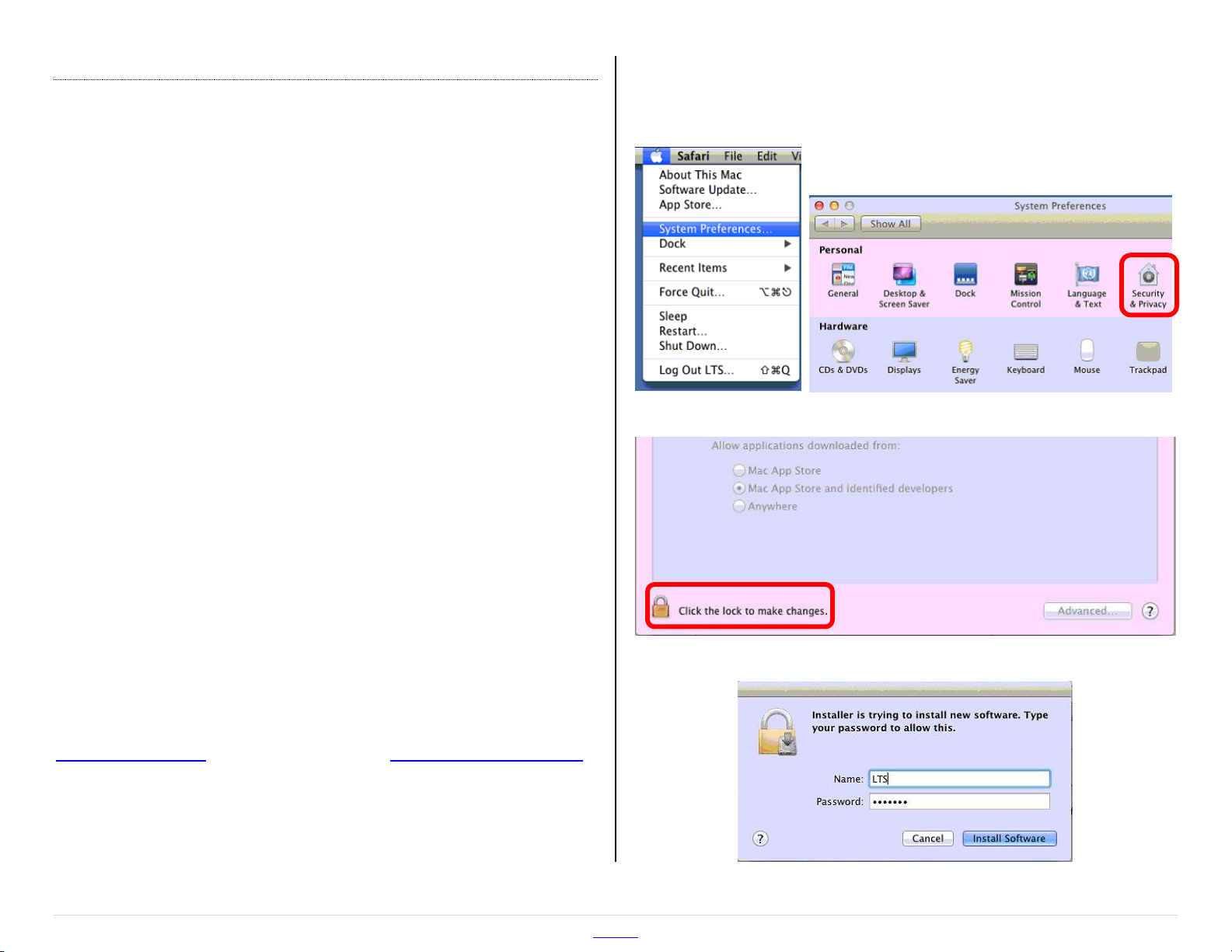
Step 3: Enable “Anywhere” Program Installation
Apple Menu > System Preferences… > Security and Privacy
Click the lock icon to allow changes to the settings.
A password will likely be required.
http://www.ltsecurityinc.com/ Menu 4 | P a g e
Page 5
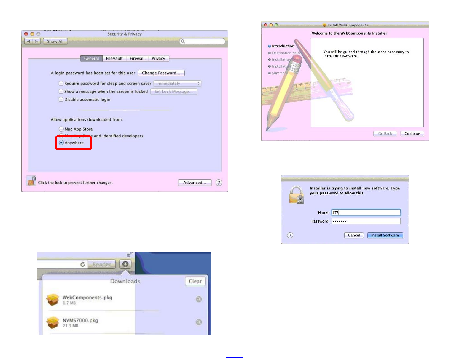
Then change the settings to allow software from “Anywhere”.
Step 4: Run the Plugin Installer
Click the download icon on the Safari toolbar.
Double click on the text “WebComponents.pkg”.
This will open the Web Component installer.
Click [Continue] and follow through with the installer. The installer will
just tell you where the files will be installed and ask for a password.
Step 5: Disable “Anywhere” Program Installation
Go back to the “Security and Privacy” settings in Step 3 and switch
“Anywhere” back to “Mac App Store and identified developers”.
Apple Menu > System Preferences… > Security and Privacy
Remember to click the lock icon to make changes. A password will be
required.
http://www.ltsecurityinc.com/ Menu 5 | P a g e
Page 6
Step 6: Quit Safari
Be sure to quit and reopen
Safari. The plugin is only loaded
when the program is first run.
(Alternatively, reboot the
computer.)
Step 7: Open Safari
Be sure to test with Safari. Chrome should work as well.
The recent version of Firefox is an overhaul and may have
problems.
Step 8: Enter the NVR's IP Address
Step 10: Allow the Plugin
Click “Plug-in blocked for this website” and then [Trust].
Step 9: Login to the NVR
Default Credentials
Username: admin
Password: 12345
http://www.ltsecurityinc.com/ Menu 6 | P a g e
Step 11: Turn on the Cameras
Click “Start All Live View” to show the cameras.
Page 7
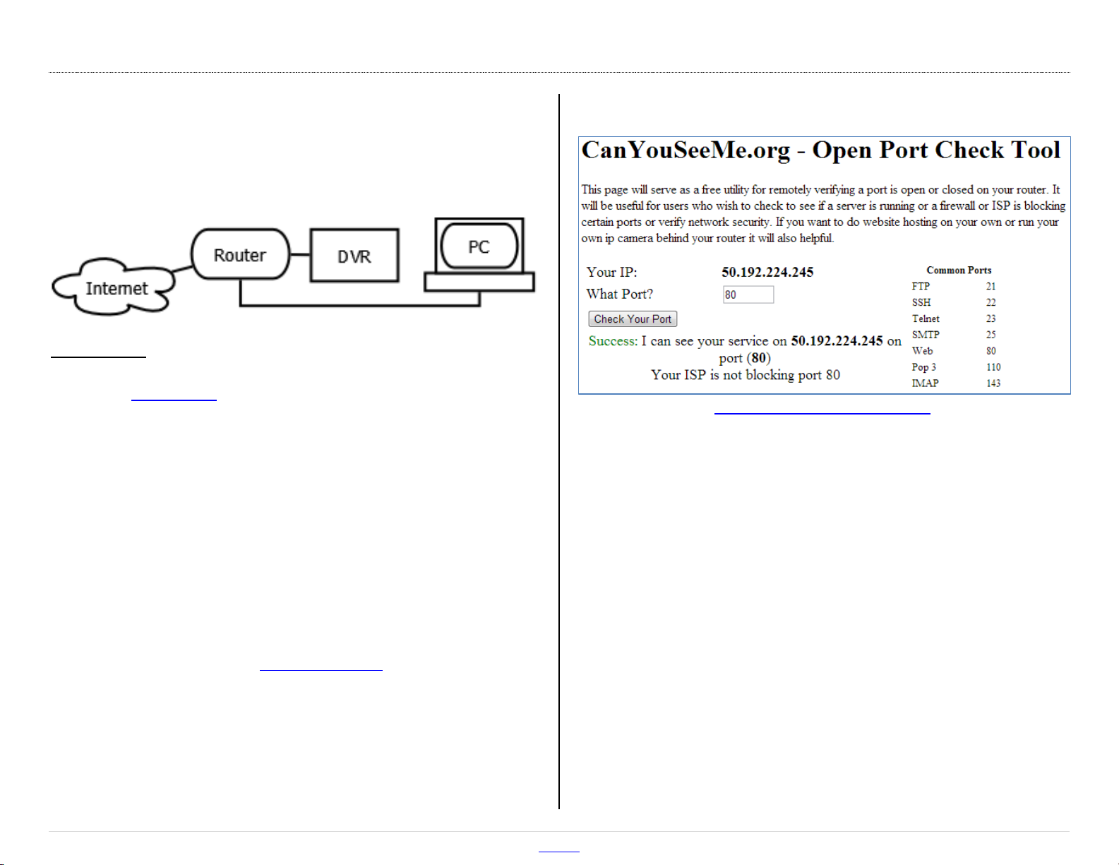
Port Forwarding
Port Forwarding
To allow remote access to the DVR/NVR, port forwarding must be
configured on the router.
The Ideal Way to Network the DVR for Port Forwarding
You will need:
A PC connected to the same router as the NVR/DVR
The IP addresses of the NVR/DVR and Router (a.k.a. Gateway)
The username and password for the router.
Step 1: Enter the IP address of the DVR/NVR into a web browser. This
should bring up the device’s web client, confirming that the
device is connected to the network.
Step 2: Enter the routers IP address into a web browser. When
prompted, enter the router’s user name and password.
Step 3: Go the port forwarding section of the router. Forward the
ports 80, 8000, & 8554 to the IP address of the NVR/DVR.
Step 4: Test the ports with canyouseeme.org to ensure that port
forwarding was successful. This also will show the outside
address of the router.
Please see the router’s manual or the following examples for
port forwarding configuration details.
CanYouSeeMe.org
http://www.canyouseeme.org/
How It Works
Port forwarding works a lot like USPS mail forwarding. With mail
forwarding, you tell the post office to forward your mail to another
address. With port forwarding, you tell the router to forward
information to another device, in this case an NVR or DVR.
A router is a network device with at least two IP addresses. Its job is to
connect two or more networks together. For an internet
router/modem, the two networks are the internet and the local
network. When you use port forwarding, you are really using the
outside (WAN/internet) address of the router; the router seamlessly
connects you to the NVR/DVR.
Port forwarding must be configured on the internet router. Any
connecting routers must also be configured. If something happens to
one of these devices, remote access is lost.
http://www.ltsecurityinc.com/ Menu 7 | P a g e
Page 8
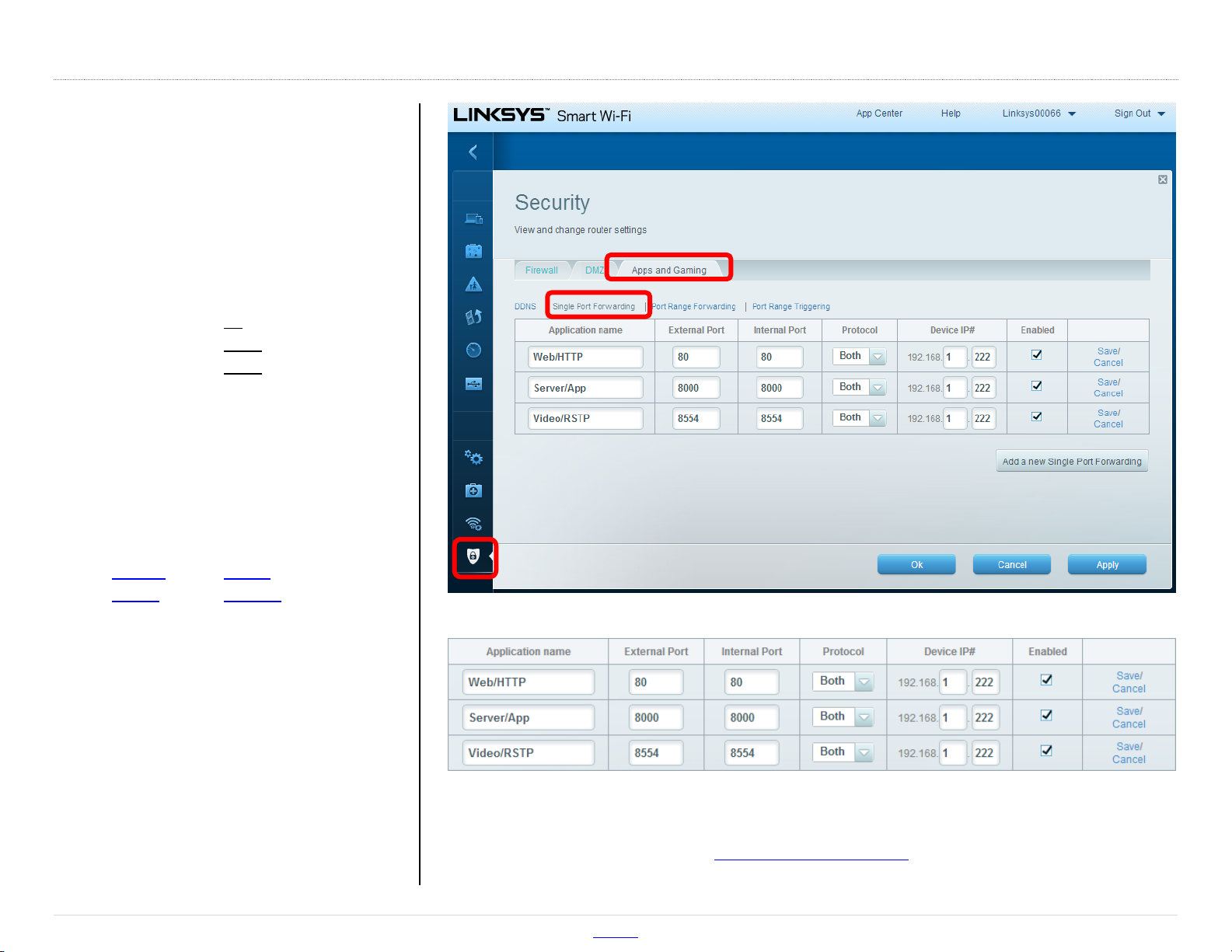
In this example, a newer Linksys router is
being configured. An example address of
“192.168.1.222” is being used. The settings
are under:
Security >
Apps and Gaming >
Single Port Forwarding
Ports to Forward: 80 (web/HTTP)
8000 (server/app)
8554 (video/RTSP)
Please note that each router is different.
Even the same manufacturer may use
different interfaces. Please see the router’s
manual for details. Often the manuals can
be found on the manufactures website.
Router Support Sites:
Linksys Belkin
D-Link Verizon
Port Forwarding may also be called
“Applications and Games,” “Pin Holes,”
“Virtual Servers,” etc.
Common default username/passwords:
admin/password
admin/admin
admin (blank password)
Port Fwd. Ex. 1 (Newer Linksys)
Practice Router Simulator
http://www.ltsecurityinc.com/ Menu 8 | P a g e
Page 9
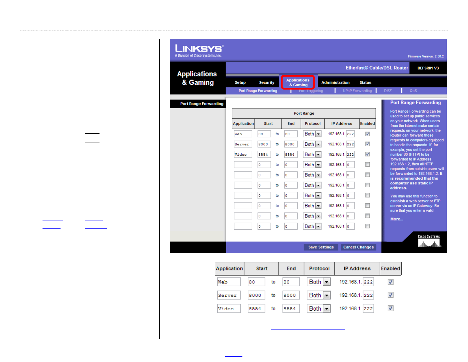
In this example, an older Linksys router is
being configured. An example address of
“192.168.1.222” is being used. Port
forwarding is under:
Applications & Games >
Port Range Forwarding
Ports to Forward: 80 (web/HTTP)
8000 (server/app)
8554 (video/RTSP)
Please note that each router is different.
Even the same manufacturer may use
different interfaces. Please see the router’s
manual for details. Often the manuals can
be found on the manufactures website.
Router Support Sites:
Linksys Belkin
D-Link Verizon
Port Forwarding may also be called
“Applications and Games,” “Pin Holes,”
“Virtual Servers,” etc.
Common default username/passwords:
admin/password
admin/admin
admin (blank password)
Port Fwd. Ex. 2 (Older Linksys)
Practice Router Simulator
http://www.ltsecurityinc.com/ Menu 9 | P a g e
Page 10

DDNS Registration and Setup
A consistent address is needed at the customer’s location to reach the
NVR/DVR. If the outside (WAN) address of the location changes
frequently, then a DDNS address can be assigned to it.
The DDNS Website: http://ns1.dvrlists.com/
Registration
There is a link to register on the website. The e-mail address should
belong to the installer. The e-mail address is the username.
Address (Domain) Creation
Once registered, an address can be created. This will be the web
address that the customer uses to reach the NVR/DVR.
In this example we are trying to create a web address, also called a
“domain”. After registering for the first time, this page will
automatically show up.
The address for the customer to use should be entered here. In this
example, the name we are trying to make is:
customeraddress.dvrlists.com
Click “Request Domain” to see if the address is available. If not, try
another address.
To add more addresses, go to the bottom of the “Domains” page.
The result will be a list of the installer’s customers’ DDNS sites.
http://www.ltsecurityinc.com/ Menu 10 | P a g e
Page 11

Entering the DDNS
Once the DDNS address is created, it can be entered into the
NVR/DVR. The DDNS settings are under:
Configuration > Network Settings > DDNS
Click the check box next to Enable
Device Domain Name is the address just created.
User Name is the installer’s e-mail address.
Password is for the DDNS account created.
Confirm is the DDNS password again.
The password is not the e-mail account password.
The default DDNS type is “LTS” and the default server is
“ns1.dvrlists.com” (our server). Leave this information alone.
Click “Test” to make sure the information has been entered correctly.
Troubleshooting
If the test fails, check the information. If it is correct, check the DNS
status. If no address has been set to the DNS, set it to: 8.8.8.8
(Googles DNS server).
Please note that DDNS and DNS are separate things.
The DVR/NVR needs a DNS to use the address of the DDNS server.
Every web address has a number attached to it. The words are for
humans; the numbers are for machines. The DNS translates the
human-readable site into machine-readable numbers.
How It Works
A DDNS will keep track of dynamically changing router IP addresses.
The NVR will “check-in” with an LTS server, telling it what its current IP
address is. Our DDNS server will then update the address created for
the customer by the installer.
Tip: Copy and paste the “Domain” and “User Name” fields from the
account page to the configuration page to prevent typos.
http://www.ltsecurityinc.com/ Menu 11 | P a g e
Page 12

Basic Usage
View Cameras
By default, no cameras show on the NVR’s web client. This conserves
bandwidth and gives the user the option to select a specific view and
cameras. Click “Start All Live View” to show the cameras.
Playback
Single View (Default)
Playback > (pick a camera) > Play ()
This will start playback of a camera from midnight of that morning.
The data and time can be specified. The time bar will be red for
recordings and can be dragged back and forth with the mouse.
A browser can be set to “Auto Start Live View” from the start.
Configuration > Local Configuration > Auto Start Live View
http://www.ltsecurityinc.com/ Menu 12 | P a g e
Multi View
Click the 2x2 option. Each playback window works like an
individual player. Click a window, click a camera, pick a
time, and click play (). Be sure to click stop () before
switching to another camera.
Page 13

Download Video
Click the download button to bring up a file list window. The
video files are organized by time. Only files for the selected
camera will be shown.
Select the desired files by clicking the check box next to them. Then
click the [Download] button.
Note: To play the files, use the Platinum Player and just drag-and-
drop the video files on the program. No installation is required.
(Alternatively, VLC Player will also work for video-only files.)
Log Search
Log > [ 🔍 ] (search)
This will search everything for the day, which may be too much.
Selecting a Major Type or time can help greatly. Selecting a minor type
often allows for a specific search over longer periods of time.
Major Types
Alarm: Anything that can trigger recording
Exception: Alerts of internal problems
Operation: User activity
Information: NVR internal activity
Minor Types are too numerous to
mention. They are a breakdown of what
each Major Type includes. To select one,
a major type must be selected first. To
the right is an example of a useful Minor
Type search that finds any shutdown not
initiated by the user or NVR.
Note: The log search will stop after 2,000
entries have been found.
http://www.ltsecurityinc.com/ Menu 13 | P a g e
Page 14

Configuration
All of the settings are under the “Configuration” tab. Initially, this
brings up basic information about the NVR.
All of the settings fall under two categories: Local and Remote.
Local Configuration controls settings for that specific web browser.
Remote Configuration controls settings for the NVR itself.
File Download Location
Click on: “Local Configuration”
Then click on [Browse] to change the save locations.
Video Stream Quality
Click on: “Local Configuration”
The default quality for “Live View Performance” is “Balanced”.
Changing it to “Shortest Delay” will reduce dropped frames by
reducing color depth and bandwidth. It can be very effective and
helpful.
http://www.ltsecurityinc.com/ Menu 14 | P a g e
Page 15

The default “Stream Type” is “Sub Stream”. It should only be changed
to “Main Stream” if the computer is on the local network. It uses
much more bandwidth.
The “Protocol” is “TCP” by default. Changing it to “UDP” can have a
slight performance increase on a stable network, but only if both UDP
and TCP ports have been forwarded. It often is unnoticeable.
The “Auto Start Live View” makes the cameras load without clicking
the “Start All Live View” button. The “Resume Live View Status” only
restores the number of cameras shown (1x1, 2x2, 3x3, or 4x4).
Camera Names
Configuration > Camera Setup > Display Settings
Video Quality
Configuration > Camera Settings > Video Settings
Each NVR has a different amount of bandwidth. Typically, the cameras
will automatically configure themselves. They can be optimized to
conserver HDD space and bandwidth. They can also be optimized for
quality, sacrificing space, bandwidth, and possibly channels. Each
resolution, frame rate, and quality has a different recommended max
bitrate (recommendations are on the NVR itself).
Substream is a low resolution video feed that is not recorded (thus,
does not affect HDD space). Because lower resolution can use less
bandwidth, substream is used to view multiple cameras feeds at once.
Substream Defaults & Possible Optimization
Video quality is a full topic on its own. For mainstream, 4096 Kpbs for
http://www.ltsecurityinc.com/ Menu 15 | P a g e
2.1 or 3 MP, with medium quality and real-time, is recommended.
Page 16

Schedule
Configuration > Camera Settings > Schedule Settings
Motion Detection Fine Tuning
Configuration > Camera Settings > Motion Detection
By default, recording is on motion detection. To edit this, click [Edit].
The red grid is where motion is detected and can be cleared for
redrawing. Move the slider to the right for higher sensitivity.
http://www.ltsecurityinc.com/ Menu 16 | P a g e
Page 17

E-mail Alerts Setup
Setting up e-mail alerts involves two steps:
1) Setting up a sender e-mail account
2) Selecting cameras to receive alerts from
It is best to create a new address to use as a dedicated sending
account. Gmail has been a reliable free service. This address will be
the “Sender” account; the customer’s current address will receive emails from the sender account.
E-mail Settings
Configuration > Network Settings > Email
An Example Gmail Configuration
Click “Test” to make sure the information has been entered correctly.
The following configuration is an example of configuring the NVR to
use a Gmail account (senderaccnt@gmail.com) to send e-mail to a
customer (customer@email.com).
Note: The “Sender” and “Receiver” fields are just labels.
http://www.ltsecurityinc.com/ Menu 17 | P a g e
Tip: You can use the “Email Schedule” tab to specify when to
receive and not receive e-mail alerts.
Page 18

Troubleshooting
If the test fails, check the information. If it is correct, check the
DNS status. If no address has been set to the DNS, set it to: 8.8.8.8
(Google’s DNS server).
Select Cameras
Once the e-mail sender account has been configured, each camera
must be told to send an e-mail alert. These settings are under:
Configuration > Camera Settings > Motion Detection > Linkage Method
Firmware Version/Upgrade/Downgrade
Firmware Version
Configuration > Device Parameters > Device Information
Firmware Upgrade
First, make note of the model of the NVR. It is always shown on top,
left of the web page:
Add a check mark to the “Send Email” settings.
Do this for each camera that needs an e-mail alert.
Snapshots are in D1 resolution.
Note: Please limit the area to the smallest possible size. All motion
will trigger an e-mail (passing cars, windblown trees, etc.).
http://www.ltsecurityinc.com/ Menu 18 | P a g e
Second, download the latest version of the firmware from the
Platinum Download page. Make sure to find your model number on
the page and extract the firmware from the .zip file.
Third, go to the Maintenance section of the web client:
Configuration > Maintenance
Page 19

Configuration > Maintenance
Then click [Browse] and go to the extracted firmware file.
Reboot/Restore/Default
Configuration > Maintenance
Then click [Upgrade] to upload the file to the NVR and start the
upgrade process.
Firmware Downgrade
To downgrade firmware, follow the same steps, but retrieve the
download from the firmware archive.
http://www.ltsecurityinc.com/ Menu 19 | P a g e
Reboot = Reboot the device.
Restore = Reset all the parameters, except the IP parameters and user
information, to the default settings.
Default = Restore all parameters to default settings.
Page 20

IP Camera Web Client
Accessing the IP Camera
Find the IP Addresses of the Cameras
The easiest way to get to the camera is from the NVR itself. The NVR
has a list of cameras connected to it.
Configuration > Camera Management > IP Camera
Connect to IPCs from a Built-in (Internal) PoE Switch
These cameras are isolated from the rest of the network. They can still
be reached, but only from a computer (such as a laptop) that is
patched directly into the PoE port.
Alternatively, the SADP tool (IP search program) can also be used.
Connect to IPCs from an External PoE Switch
A computer connected to the same router/switch as the IPCs should
be able to access the cameras easily. Simply type the IPC’s address
into the address bar of a web browser, just like for the NVR.
The patched in computer will need its IP address changed to be able to
connect to the IPCs. Something similar to:
192.168.188.(unused-number)
An Example that Is Commonly Available:
192.168.188.237
The NVR will be 192.168.188.1 and the cameras typically will be similar
in their numbers and low. The IPCs are given numbers in the order are
added, but moving them around can shift the numbers higher. Always
check the camera list to see what numbers are unavailable.
Once patched in, type the IPC’s address into the address bar of a web
browser, just like for the NVR.
Tip: Wi-Fi can cause problems when connecting to the built-in PoE
ports. If needed, turning it off can help. Be sure to turn it back
on when finished. The patch in is meant to be temporary.
http://www.ltsecurityinc.com/ Menu 20 | P a g e
Page 21

Advanced Direct Access to All Cameras
(LTN7700 Series with April 2014 (1404+) Firmware)
If the NVR is in the LTN7700 series (e.g. LTN7732-P8, LTN7716-P16),
then there is a way to enable access to the cameras through the NVR.
This is done through the “Virtual Hosts” feature. By default, this is
turned off, but can be turned on from the network settings:
Configuration > Network Settings > Advanced
Enable “Virtual Hosts” and click the [Save] button.
Configuration > Camera Management > IP Camera
Address 192.168.1.28 is the NVR. Notice the how the built-in ports
(D01-D08) use different network port numbers with the DVR’s address.
The rest of the camera use their own IP address and port 80.
Once this is enabled, all of the cameras can be reached. There are
even links that can be clicked on. To see the camera list and the links,
go to the Camera Management section (not Camera Settings).
http://www.ltsecurityinc.com/ Menu 21 | P a g e
Camera Link Examples
Channel 1 (built-in PoE): http://192.168.1.28:65001
Channel 11 (external PoE): http://192.168.1.12:80
Note: This method will only work on the local network, not remotely.
In other words, it will work onsite, but not offsite.
Page 22

Basic Usage
Snapshot/Clip Locations
To see/control the location of the picture/clip:
Configuration > Local Configuration
Camera Live View with PTZ controls turned on.
[4:3] [16:9] [x1] [Auto] [Sub/Main Streams] [Plugin] [PTZ Show/Hide]
The 4:3, 16:9, x1 and Auto buttons control the aspect ratio (e.g. 720P
and 1080P are 16:9 ratio). The x1 is very useful because it shows the
Then click [Browse] for each location to change where the files will be
saved.
true size of the video feed; a 3MP camera will be larger than the
computer screen.
Take a picture of, record a clip from,
or zoom-in on the video.
Auto Focus for Motorized Varifocal IPCs
(CMIP###-Z cameras only)
http://www.ltsecurityinc.com/ Menu 22 | P a g e
Page 23

Firmware Version/Upgrade/Downgrade
Firmware Version
Configuration > System > Device Information
Firmware Upgrade
Configuration > System > Maintenance
This is often the first page of the Configuration pages.
First, note the model number at the top left of the page (CMIP3923-Z
in this case).
Second, find the corresponding firmware on the Platinum Download
page. Be sure to extract the firmware from the .zip container.
Third, click [Browse] and select the extracted firmware file. Then click
[Upgrade] to upload the firmware to the IPC and initiate the upgrade.
Firmware Downgrade
To downgrade firmware, follow the same steps, but retrieve the
download from the firmware archive.
http://www.ltsecurityinc.com/ Menu 23 | P a g e
Page 24

Reboot/Restore/Default
Configuration > System > Maintenance
Image & Audio Settings
Configuration > Image > Display Settings
Reboot = Reboot the device.
Restore = Reset all the parameters, except the IP parameters and user
information, to the default settings.
Default = Restore all parameters to default settings.
Most of the settings of an IP camera can be accessed from the NVR
itself. Sometimes features are added to cameras that are not
immediately included in the NVR. (This is especially true if the IPC
firmware came out after the NVRs.) Those features can only be
accessed from the camera’s web client.
Note: Different models and different firmware have different features!
+NVR = Available from the NVR directly.
-NVR = Not currently on the NVR.
+/-NVR = Some features are on the NVR, but typically aren’t needed.
http://www.ltsecurityinc.com/ Menu 24 | P a g e
Page 25

Standard Color controls. +NVR
Iris and Exposure controls. It is best to leave these alone. +NVR
Gain helps night pictures, but may make bright lights brighter. -NVR
WDR (Wide Dynamic Range) control is typically off by default. -NVR
It is useful in mild cases of bright/dark mixes.
A TrueWDR IP camera will have better results.
This setting attempts to account for lighting. +NVR
AWB means “Auto White Balance” and typically works well.
DNR reduces random, tiny discoloration to smooth an image. -NVR
This can sometimes help the clarity of a speckled image.
Note: This is just an example of one camera.
Day/Night switch settings are typically unneeded. +/-NVR
http://www.ltsecurityinc.com/ Menu 25 | P a g e
Page 26

Mirror is used to rotate an image 180° (change to “Centered”). +NVR
Rotate is used for 90° turn. This not on older firmware or all models
and may cause distortion.
Change Camera Name Internally
Configuration > Advanced Configuration > Image > OSD Settings
Change the Sound Settings
For models that support sound (typically ending with “-S”) the default
internal volume of the camera is at 50%. You can double the volume in
the audio settings.
Configuration > Video/Audio > Audio
Move the slider all the way to the right to maximize the volume to 100.
Tip: MicIn is for an unpowered microphone.
LineIn is for a powered/amplified microphone.
Click and drag the text to move them around.
http://www.ltsecurityinc.com/ Menu 26 | P a g e
Page 27

Can’t See Video on Monitor
NVR Not Recording
DDNS Not Working
NVR Acting Strangely
Cameras Disappear After Upgrade
Choppy Video
Troubleshooting
The web client can be used to check and control the video output. The SADP tool will have to
be used to find the NVR’s address.
Configure > Remote Configure > Device Parameters > Menu Output
Check HDD
Check Schedule
Check Motion Settings
Check Primary DNS
Check the Gateway
Copy and paste link & user from ns1.dvrlists.com
Try using another browser (or switch IE to Compatibility Mode).
Reboot the NVR
Reset Settings (Factory Default)
Update or Downgrade Firmware
(See the Maintenance page.)
Change the Video Stream Quality in the Local Configuration.
Add them back from:
Configuration > Camera Management > IP Camera
Then click [Quick Add], select the cameras, and click [OK] to add them.
http://www.ltsecurityinc.com/ Menu 27 | P a g e
Page 28

Camera Initialization
No Channel Position Saving
Isolated IPC Web Client on Built-in PoE
Cannot Remotely Reset Password
Mac Web Client Is a Separate Download
Limitations
One-Click camera initialization is from the NVR only. The SADP tool can be used to manually
find cameras and assign them IP#s. They can then be added from the web client.
Configuration > Remote Configuration > Camera Management > IP Camera
Cameras will be positioned in the order in which they are added. Those positions can be
changed manually, but not saved. The camera order itself needs to be changed for the camera
positions to be saved.
Cameras connected to the built-in PoE switch are isolated from the network. This reduces or
eliminates IPC bandwidth on the network, a potential issue. This also means the IPCs can only
be configured from the NVR itself or by patching into the built-in PoE ports directly. (The latest
firmware for the LTN7700 series can allow access through the NVR.)
Password resets (covered in the main Platinum Guide) can only be performed on the NVR itself.
They cannot be performed by any other means. They cannot be performed by with the web
client or other tools.
The Mac compatible version of the web client is not available from the NVR itself (the Windows
version is). The Mac version must be downloaded separately. See the Mac Installation section.
(Mac web client current version is 3.x; Windows is 5.x)
Written by Ryan D. Lang
http://www.ltsecurityinc.com/ Menu 28 | P a g e
 Loading...