

Page 1
Quick Info
Default Username: admin
Default Password: 12345
Default Resolution: 1920x1080P (HDMI)
Default Recording: Motion
Default NVR IP#: 192.0.0.64
(DHCP is off)
App Name: NVMS7000
(iPhone/iPad & Android)
DDNS Web Site: http://ns1.dvrlists.com
Ports to Forward: 80 (web/HTTP)
8000 (server/app)
8554 (video/RTSP)
Player Software: Player.exe
Onvif Version: 2.2 Profile S
IP Scanner: SADP
Platinum Guide
Table of Contents
Networking the NVR, IPC, & External PoE ........ 2
Assign or Find the NVR’s IP Address ................. 3
Scanning & Adding IP Cameras ......................... 4
Camera Configuration (Picture / Name) ........... 6
Camera Positioning ........................................... 7
Recording (Motion / Fulltime) .......................... 8
Port Forwarding ................................................ 9
Port Fwd. Ex. 1 (Newer Linksys) .................. 10
Port Fwd. Ex. 2 (Older Linksys) .................... 11
DDNS Registration and Setup ......................... 12
Search & Playback (Normal / Smart) .............. 14
Backup & Export.............................................. 15
Single Clip Backup (Snipping) ...................... 17
E-mail Alert Setup ........................................... 18
Resetting the Password .................................. 20
NVMS7000 Setup ............................................ 21
RTSP Video & JPEG Image ............................... 23
Troubleshooting .............................................. 24
Tips
The built-in PoE ports are plug-and-play,
requiring no configuration for Platinum IP
cameras. The cameras will be arranged in
order by port number.
See the Platinum Download Page for the latest
firmware and software.
Be sure to close and reopen Firefox, Chrome,
or Safari after installing the web component.
The Mac web component for Safari is available
from the Platinum Download Page.
The USB ports on the front and back can be
used for either the mouse or a flash drive.
It helps to plan out IP addresses in advance and
label Ethernet cords. This aids organization
and troubleshooting.
It is often easier to copy and paste the DDNS
information from the ns1.dvrlists.com site into
the web interface. This prevents typos.
http://www.ltsecurityinc.com/ ▲ A u t h o r – R y a n D L a n g 1 | P a g e
Page 2
Warning
!
!
The NVR should be connected to the network
from its single LAN port. If the NVR comes
with built-in PoE ports, they should only be
connected to IP cameras.
The built-in PoE ports should not be
connected to a switch or router.
Only PoE powered IP cameras should be
connected to the built-in PoE switch.
Turn off power on external PoE switch ports
that are not connect to an IP camera.
The LAN port of the NVR can be connected to
a router, a switch, or an unpowered port of a
PoE switch.
IP cameras connect to the built-in PoE port
are isolated from the rest of the network.
This conserves bandwidth, but restricts IPC
configuration to the NVR.
http://www.ltsecurityinc.com/ ▲ A u t h o r – R y a n D L a n g 2 | P a g e
Connecting the NVR to the Network
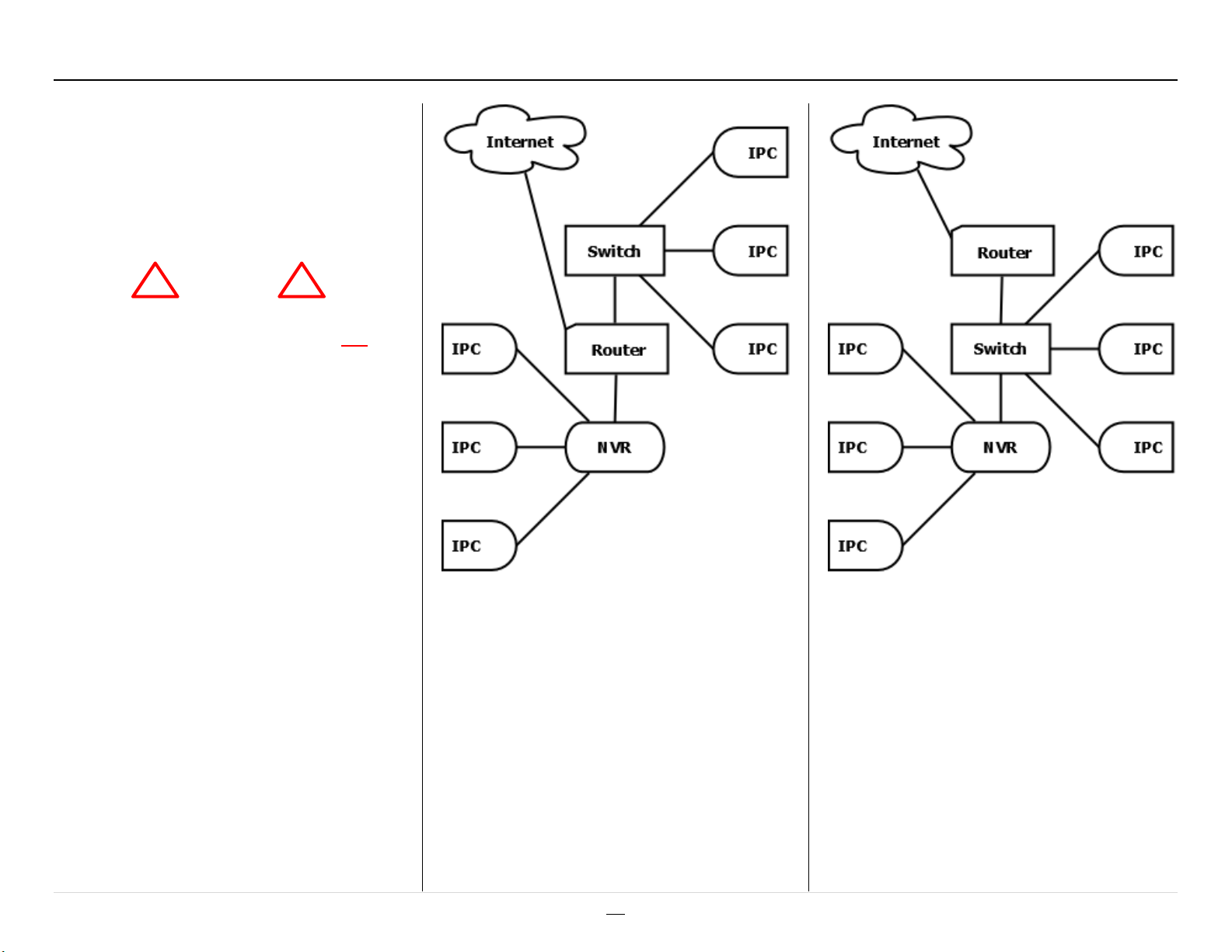
Networking the NVR, IPC, & External PoE
PoE Switch and NVR to Router
+ Easier setup; uses one switch port
- No bandwidth isolation for PoE switch
NVR to PoE Switch to Router
+ Bandwidth isolation
- Uses another port on the PoE switch
Page 3
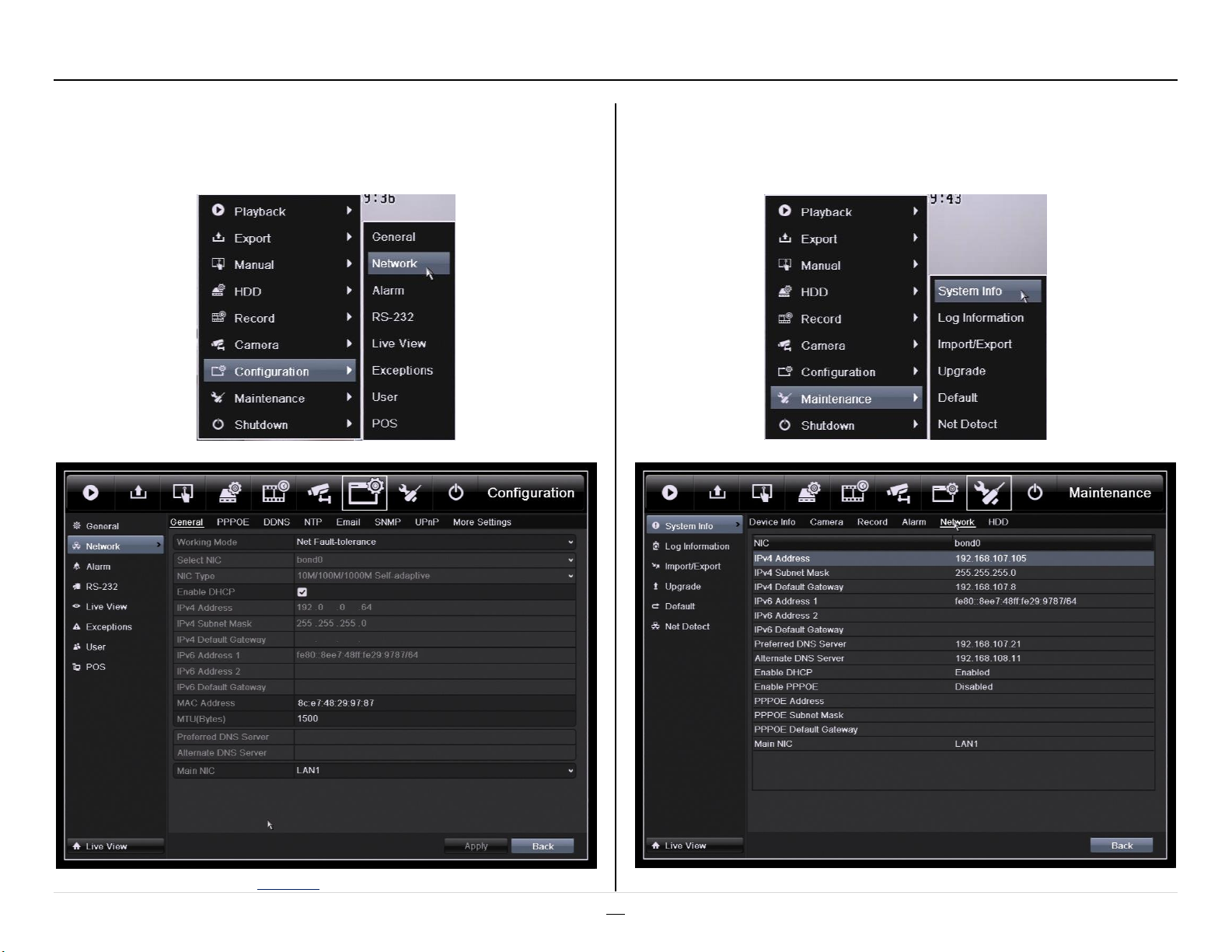
To reach the network settings, go to:
Menu > Configuration > Network
Assign or Find the NVR’s IP Address
The current network settings are also in Maintenance:
Menu > Maintenance > System Info > Network
By default DHCP is disabled. The IP address is 192.0.0.64
http://www.ltsecurityinc.com/ ▲ A u t h o r – R y a n D L a n g 3 | P a g e
Page 4
Scanning & Adding IP Cameras
Warning
!
!
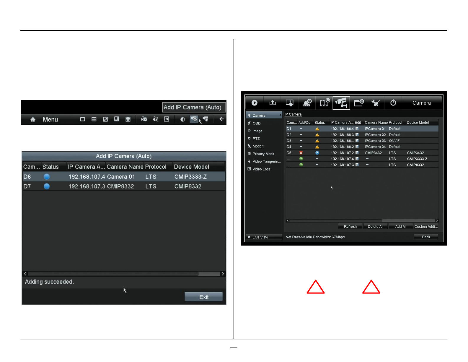
1-Click Camera Adding
As of the December 2013 firmware update, the NVRs can quickly add
all cameras with a single click. The NVR will scan for, assign addresses
to, and add cameras. The button is on the toolbar at the bottom of the
screen (right click to display).
The NVR will show the cameras that it found and added.
Single Camera Adding
The NVR has built-in tools to scan for and add the IP cameras
individually. The tool is located under:
Menu > Camera > Camera
http://www.ltsecurityinc.com/ ▲ A u t h o r – R y a n D L a n g 4 | P a g e
Click on the plus sign (+) to add a camera. The camera will be given a
free IP address.
Make sure the NVR has an IP address on the local network.
Page 5
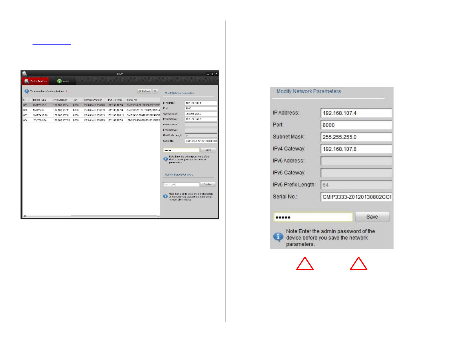
Scanning from the IP Tool (SADP)
Warning
!
!
The IP tool (SADP) can be used from a Windows® computer to scan for
Platinum devices. This allows configuration of the IP addresses for IP
cameras, NVRs, and even DVRs.
The device’s IP address and Gateway (router) can be set from here.
The device’s password must be entered for changes to be accepted.
The default password is:
12345
The devices should show up automatically. It checks every few
seconds. Click refresh to force it to check again and to remove devices
that are no longer there.
Click on a device to see its current information.
http://www.ltsecurityinc.com/ ▲ A u t h o r – R y a n D L a n g 5 | P a g e
The “Port:” is the server port used by the NVMS7000 or by the NVR.
The “Port:” is not the web (HTTP) port.
Page 6
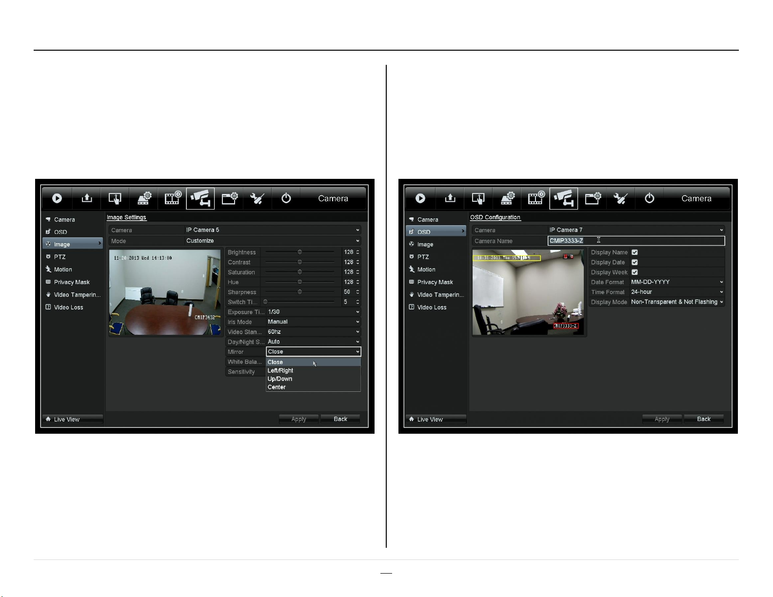
Camera Configuration (Picture / Name)
Adjusting a Camera’s Picture
The camera image can be adjusts is a variety of ways (e.g. rotated
180°). Please note that the camera, itself, is being configured from the
NVR. These options are under:
Menu > Camera > Image
Changing a Camera’s Name
By default, each camera is named “CAMERA01.” This is because the
name of each camera is stored, not on the NVR, but on the camera
itself. The name can be changed from:
Menu > Camera > OSD
To rotate an image, change the “Mirror” setting to “Center”.
Note: If the IP camera is connected to an external PoE switch, then the
camera can be configured directly from its web client.
http://www.ltsecurityinc.com/ ▲ A u t h o r – R y a n D L a n g 6 | P a g e
Note: It is often easier to use the web component for this task. It is
easier to type from a computer. A keyboard cannot be used with the
NVR.
Page 7
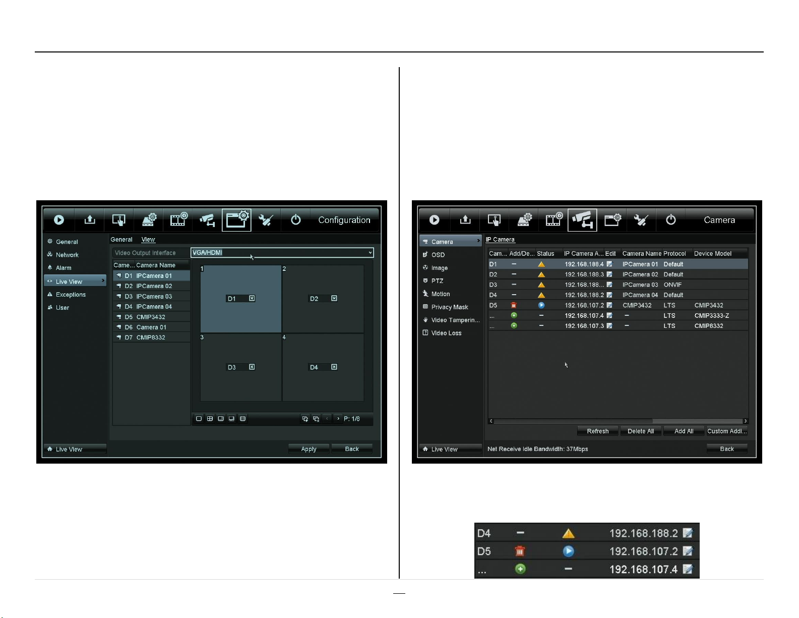
Camera Positioning
Moving Camera Feeds
Camera feeds can be rearranged on the NVR’s display. Click the [X] to
remove a feed. Click the screen position and then a camera’s icon ()
to add that camera. Use the left arrow [<] and right arrow [>] to see
more screens (if the cameras won’t all fit into one).
Menu > Live View > View
Changing Camera Order
Cameras connected to the built-in PoE switch are in the order of the
ports that they are connected to. Cameras connected to an external
PoS switch are in the order they were added. They can be removed
and added again to change their order.
Menu > Camera > Camera
To change the spotout (if available), switch the “VGA/HDMI” to “CVBS”
and reorganize the camera feeds.
Note: Moving the camera feeds will not affect the web client.
Changing the camera order will affect the web client.
http://www.ltsecurityinc.com/ ▲ A u t h o r – R y a n D L a n g 7 | P a g e
Trash Can = delete Triangle (!) = error
Circle (+) = add Circle () = play
Page 8
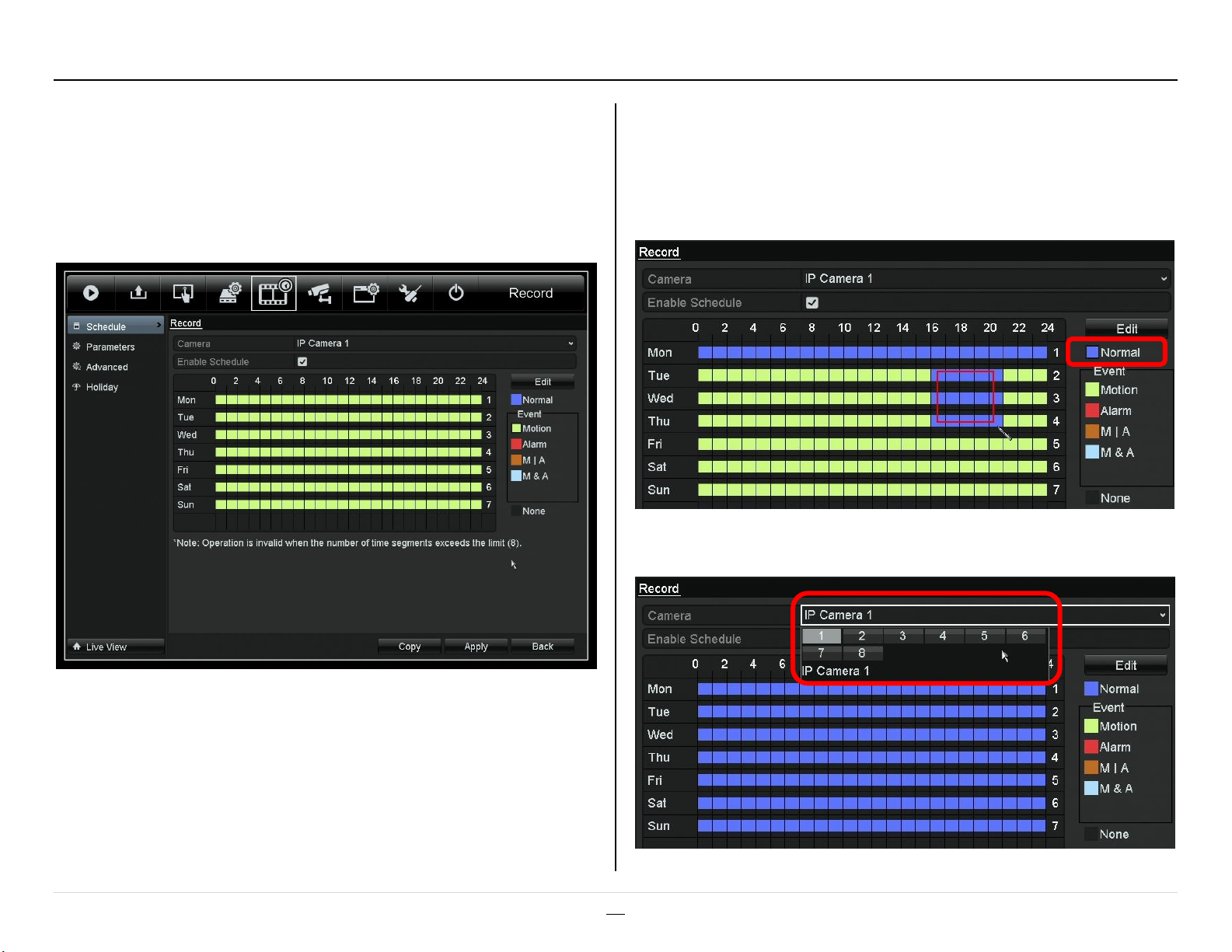
Recording (Motion / Fulltime)
Motion Detection
By default, the Platinum NVRs/DVRs are set to record on motion. To
change the schedule, go to:
Menu > Record > Schedule
Fulltime Recording
To schedule specific recording times:
Click “Normal”
Select an area
Be sure to change settings for each camera and click “Apply”.
Motion recording is indicated as a pale green/yellow.
Scheduled recording times will be blue.
Fulltime (“Normal”) recording will be completely blue.
http://www.ltsecurityinc.com/ ▲ A u t h o r – R y a n D L a n g 8 | P a g e
Page 9

Port Forwarding
Port Forwarding
To allow remote access to the DVR/NVR, port forwarding must be
configured on the router.
The Ideal Way to Network the DVR for Port Forwarding
You will need:
A PC connected to the same router as the NVR/DVR
The IP addresses of the NVR/DVR and Router (a.k.a. Gateway)
The username and password for the router.
Step 1: Enter the IP address of the DVR/NVR into a web browser. This
should bring up the device’s web client, confirming that the
device is connected to the network.
Step 2: Enter the routers IP address into a web browser. When
prompted, enter the router’s user name and password.
Step 3: Go the port forwarding section of the router. Forward the
ports 80, 8000, & 8554 to the IP address of the NVR/DVR.
Step 4: Test the ports with canyouseeme.org to ensure that port
forwarding was successful. This also will show the outside
address of the router.
Please see the router’s manual or the following examples for
port forwarding configuration details.
http://www.ltsecurityinc.com/ ▲ A u t h o r – R y a n D L a n g 9 | P a g e
http://www.canyouseeme.org/
Port forwarding works a lot like USPS mail forwarding. With mail
forwarding, you tell the post office to forward your mail to another
address. With port forwarding, you tell the router to forward
information to another device, in this case an NVR or DVR.
A router is a network device with at least two IP addresses. Its job is to
connect two or more networks together. For an internet
router/modem, the two networks are the internet and the local
network. When you use port forwarding, you are really using the
outside (WAN/internet) address of the router; the router seamlessly
connects you to the NVR/DVR.
Port forwarding must be configured on the internet router. Any
connecting routers must also be configured. If something happens to
one of these devices, remote access is lost.
CanYouSeeMe.org
How It Works
Page 10

In this example, a newer Linksys router is
being configured. An example address of
“192.168.1.222” is being used. The settings
are under:
Security >
Apps and Gaming >
Single Port Forwarding
Ports to Forward: 80 (web/HTTP)
8000 (server/app)
8554 (video/RTSP)
Please note that each router is different.
Even the same manufacturer may use
different interfaces. Please see the router’s
manual for details. Often the manuals can
be found on the manufactures website.
Router Support Sites:
Linksys Belkin
D-Link Verizon
Port Forwarding may also be called
“Applications and Games,” “Pin Holes,”
“Virtual Servers,” etc.
Common default username/passwords:
admin/password
admin/admin
admin (blank password)
Port Fwd. Ex. 1 (Newer Linksys)
Practice Router Simulator
http://www.ltsecurityinc.com/ ▲ A u t h o r – R y a n D L a n g 10 | P a g e
Page 11

Port Fwd. Ex. 2 (Older Linksys)
In this example, an older Linksys router is
being configured. An example address of
“192.168.1.222” is being used. Port
forwarding is under:
Applications & Games >
Port Range Forwarding
Ports to Forward: 80 (web/HTTP)
8000 (server/app)
8554 (video/RTSP)
Please note that each router is different.
Even the same manufacturer may use
different interfaces. Please see the router’s
manual for details. Often the manuals can
be found on the manufactures website.
Router Support Sites:
Linksys Belkin
D-Link Verizon
Port Forwarding may also be called
“Applications and Games,” “Pin Holes,”
“Virtual Servers,” etc.
Common default username/passwords:
admin/password
admin/admin
admin (blank password)
http://www.ltsecurityinc.com/ ▲ A u t h o r – R y a n D L a n g 11 | P a g e
Practice Router Simulator
Page 12

DDNS Registration and Setup
A consistent address is needed at the customer’s location to reach the
NVR/DVR. If the outside (WAN) address of the location changes
frequently, then a DDNS address can be assigned to it.
The DDNS Website: http://ns1.dvrlists.com/
Registration
There is a link to register on the website. The e-mail address should
belong to the installer. The e-mail address is the username.
Address (Domain) Creation
Once registered, an address can be created. This will be the web
address that the customer uses to reach the NVR/DVR.
In this example we are trying to create a web address, also called a
“domain”. After registering for the first time, this page will
automatically show up.
The address for the customer to use should be entered here. In this
example, the name we are trying to make is:
customeraddress.dvrlists.com
Click “Request Domain” to see if the address is available. If not, try
another address.
To add more addresses, go to the bottom of the “Domains” page.
The result will be a list of the installer’s customers’ DDNS sites.
http://www.ltsecurityinc.com/ ▲ A u t h o r – R y a n D L a n g 12 | P a g e
Page 13

Entering the DDNS
Once the DDNS address is created, it can be entered into the
NVR/DVR. The DDNS settings are under:
Menu > Configuration > Network > DDNS
Click the check box next to Enable
Device Domain Name is the address just created.
User Name is the installer’s e-mail address.
Password is for the DDNS account created.
Confirm is the DDNS password again.
The password is not the e-mail account password.
The default DDNS type is “LTS” and the default server is
“ns1.dvrlists.com” (our server). Leave this information alone.
Click “Test” to make sure the information has been entered correctly.
Troubleshooting
If the test fails, check the information. If it is correct, check the DNS
status. If no address has been set to the DNS, set it to: 8.8.8.8
(Googles DNS server).
Please note that DDNS and DNS are separate things.
The DVR/NVR needs a DNS to use the address of the DDNS server.
Every web address has a number attached to it. The words are for
humans; the numbers are for machines. The DNS translates the
human-readable site into machine-readable numbers.
How It Works
A DDNS will keep track of dynamically changing router IP addresses.
The NVR will “check-in” with an LTS server, telling it what its current IP
address is. Our DDNS server will then update the address created for
the customer by the installer.
http://www.ltsecurityinc.com/ ▲ A u t h o r – R y a n D L a n g 13 | P a g e
Page 14

Normal Search
To find and playback video, go to:
Menu > Playback > Normal
Select one or more cameras > Double click a day >
Slide to the desired time > Click Play
Search & Playback (Normal / Smart)
Smart Search
The Smart Search makes it easy to find video by narrowing down were
motion occurred. Make sure only one feed is selected.
Click the graph icon (“Smart”).
Use the zoom icons to magnify the time bar.
The results show up in blue.
http://www.ltsecurityinc.com/ ▲ A u t h o r – R y a n D L a n g 14 | P a g e
Select an area > Click “Search”
The results will show up in green.
Page 15

Warning
!
!
Normal Backup
Video can be exported to a USB flash drive.
Menu > Export > Normal
Backup & Export
All of the records in that range will show up.
Click the play icon to preview the files.
Specify the channels, start date/time, end date/time >
Click “Search”
Note: If the flash drive cannot be read, ensure it is FAT32 formatted.
http://www.ltsecurityinc.com/ ▲ A u t h o r – R y a n D L a n g 15 | P a g e
Select the desired files > Click “Export”
By default, all of the records are selected. If you do not want all of
the files, uncheck the top check box. Then select files individually.
Page 16

For just the video file (and log), click “OK.”
Exporting the Player Program
To export the player software:
Click “Export” again > Select “Player” > Click “OK”
Playing the Video File
Connect the USB flash drive to a computer and open it. Drag and drop
the video file onto the player program (player.exe). No installation is
required.
Tip: VLC Player can also be used to play video files. Audio may not
work; PoS text cannot be shown.
The player software can also be downloaded from our website.
http://www.ltsecurityinc.com/ ▲ A u t h o r – R y a n D L a n g 16 | P a g e
Page 17

Single Clip Backup (Snipping)
Select a single video record using a normal or smart search.
Exit the Playback screen. (X)
Click “Yes” to bring up the “Export” screen; then click “OK.”
Click “Start clipping” ()
Let the video play or click on the end of the clip’s time line.
Click “Stop clipping”
http://www.ltsecurityinc.com/ ▲ A u t h o r – R y a n D L a n g 17 | P a g e
Page 18

E-mail Alert Setup
E-mail Setting
It is best to create a new address to use as a dedicated sending
account. Gmail has been a reliable free service. This address will be
the “Sender” account; the customer’s current address will receive emails from the sender account.
The e-mail settings are under:
Menu > Configuration > Network > Email
An Example Gmail Configuration
Click “Test” to make sure the information has been entered correctly.
The following configuration is an example of configuring the NVR to
use a Gmail account (senderaccnt@gmail.com) to send e-mail to a
customer (customer@email.com).
Note: The “Sender” and “Receiver” fields are just labels.
http://www.ltsecurityinc.com/ ▲ A u t h o r – R y a n D L a n g 18 | P a g e
Troubleshooting
If the test fails, check the information. If it is correct, check the DNS
status. If no address has been set to the DNS, set it to: 8.8.8.8
(Googles DNS server).
Page 19

Channel Settings
Once the e-mail sender account has been configured, each camera
must be told to send an e-mail alert. These settings are under:
Menu > Camera > Motion > (Gear Icon) > Linkage Action
Note: Please limit the area to the smallest possible size. All motion
will trigger an e-mail (passing cars, windblown trees, etc.).
Add a check mark to the “Send Email” settings.
Do this for each camera that needs an e-mail alert.
Note: Snapshots are in D1 resolution.
http://www.ltsecurityinc.com/ ▲ A u t h o r – R y a n D L a n g 19 | P a g e
Page 20

Resetting the Password
The password is reset from the Login screen.
If needed, logout of the Platinum NVR/DVR.
To log back in, try to access the menu again.
The Login screen will appear, prompting the
user for a password.
From the Login screen, double click on the
lower, left-hand corner of the box. This is a
hidden button. It will bring up the “Restore
default password” box.
The corner is a hidden button.
Double click it.
Check to make sure the system date is
accurate. The “Secure Code” changes each
day. Please contact LTS for that day’s code,
or e-mail support@ltsnj.com alternatively.
Enter the “Secure Code” and the following
message should appear.
The “admin” account password has been
changed to:
No other settings or passwords are changed.
12345
http://www.ltsecurityinc.com/ ▲ A u t h o r – R y a n D L a n g 20 | P a g e
Page 21

NVMS7000 Setup
To begin, tap the menu button (≡) in the top,
left corner.
NVMS7000 is available for iPhone and iPad in
the Apple App Store and for Android in the
Google Play store.
http://www.ltsecurityinc.com/ ▲ A u t h o r – R y a n D L a n g 21 | P a g e
The icons refer to:
Live View – Playback – Devices – Settings
Tap the one for Devices (3rd from the left).
This will list all known devices. Tap the plus
sign (+) to add a new device.
Page 22

Enter the NVR/DVR connection information:
Alias: Just a label
Register Mode: IP/Domain (default)
Address: IP or DDNS address
Port: 8000 (default)
Username/Password: admin/12345
Tap save () in the top, right.
http://www.ltsecurityinc.com/ ▲ A u t h o r – R y a n D L a n g 22 | P a g e
The device has been added. Tap “Start live
view” to see the camera feeds. For further
changes tap the pen button () on the top,
right corner. Tap back () to return to the
Devices list.
Note: the app will auto detect how many
cameras are available.
The live view should now be displayed. If
there are more than four cameras, swipe
(slide you finger to left/right) to see the other
camera feeds.
Page 23

RTSP (Real Time Streaming Protocol) is a
standardized video streaming protocol. IP
cameras use it to provide the video to the
NVR. NVRs and DVRs use it to provide
video to the web client, app, etc.
The purpose of RTSP is to be compliant with
Onvif. RTSP sometimes is directly used by
third party NVRs or VMSs (Video
Management System).
RTSP Ports
The industry standard port for RSTP is 554.
This caused problems on some iOS devices,
so the NVRs/DVRs switched to port 8554.
Cameras: 554
NVR/DVR: 8554
Note: Custom ports can be used if needed.
A Note on Onvif
Onvif is an industry standard that allows
IPCs and NVRs from different
manufacturers to work together. The
default web and server port is 80; the
default RTSP port is 554.
LTS IP cameras use:
Onvif Version 2.2 Profile S
RTSP Video & JPEG Image
RTSP Video
rtsp://username:password@<address>:<port>/streaming/channel/<camera#><stream>
(Mainstream = 01 | Substream = 02)
Example 1: NVR/DVR Mainstream – Channel 16 (IP Address)
rtsp://admin:12345@192.0.0.64:8554/streaming/channels/1601 (Note the 8554 port)
Example 2: NVR/DVR Substream – Channel 3 (Domain Address)
rtsp://admin:12345@nvr.dvrlists.com:8554/streaming/channels/302
Example 3: IP Camera Mainstream / Substream (IP Address)
rtsp://admin:12345@192.0.0.64:554/streaming/channels/101 (Note the 554 port)
rtsp://admin:12345@192.0.0.64:554/streaming/channels/102
Note: The RTSP feed cannot be understood by a web browser. A media player plugin can be
used, but this requires HTML coding and is not supported.
Embedding video into a webpage is not supported. IPCs support six concurrent logins.
Some customers have had success with mirroring services that repeat the RTSP feed.
JPEG Image
http://username:password@<address>:<web-port>/streaming/channel/1/picture (IPC only)
Example 1: IP Camera JPEG Image (IP Address)
http://admin:12345@192.0.0.64/streaming/channels/1/picture (HTTP port defaults to 80)
http://192.0.0.64/streaming/channels/1/picture (browser requests credentials)
http://www.ltsecurityinc.com/ ▲ A u t h o r – R y a n D L a n g 23 | P a g e
Page 24

Troubleshooting
Can’t See Video on Monitor
NVR Not Recording
DDNS Not Working
Cameras Disappear After Upgrade
The web client can be used to check and control the video output. The SADP tool will have to
be used to find the NVR’s address. Type the NVR’s IP address into a web browser.
Configure > Remote Configure > Device Parameters > Menu Output
Check HDD
Check Schedule
Check Motion Settings
Check Primary DNS
Check the Gateway
Copy and paste link & user from ns1.dvrlists.com
Add them back from:
Configuration > Camera Management > IP Camera
Then click [Quick Add], select the cameras, and click [OK] to add them.
Written by Ryan D. Lang
http://www.ltsecurityinc.com/ ▲ A u t h o r – R y a n D L a n g 24 | P a g e
 Loading...