

Page 1
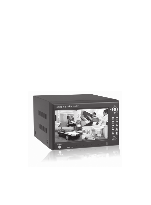
4 CH DVR
Built-in 7” LCD Monitor
USER MANUAL
*Design and specifications subject to change without notice.
Page 2
CONTENT
1 DVR features ............................................................................................................... 3
2 Introduction...................................................................................................................3
2.1 Front panel.................................................................................................................3
2.2 Back panel ................................................................................................................3
2.3 Remote Control .........................................................................................................4
3 Installation .................................................................................................................... 5
3.1 Install HDD................................................................................................................5
3.2 Install camera and monitor ..........................................................................................5
3.3 Install power supply ...................................................................................................5
4 DVR system process introduction ...................................................................................5
4.1 HDD test process.........................................................................................................5
4.2 Recover lost data process ............................................................................................6
4.3 Video recover process..................................................................................................6
4.4 Enter main screen .......................................................................................................6
5 DVR menu introduction.................................................................................................. 7
5.1 Menu introduction ...................................................................................................... 7
5.2 Set display channel .....................................................................................................7
5.3 Set video ................................................................................................................... 7
5.4 Set record mode ..........................................................................................................8
5.5 Record frame rate setting..............................................................................................8
5.6 Video quality..............................................................................................................8
5.7 Record setting ............................................................................................................8
5.8 System setting ........................................................................................................... 9
5.9 HDD setting
5.10 Motion detection setting
10
Page 3

5.11 System reset
6 Other setting......................................................................................................................................................12
6.1 Start recording .............................................................................................................................................12
6.2 Stop record ...................................................................................................................................................12
6.3 Record time ..................................................................................................................................................12
7 Playback setting................................................................................................................................................13
8 USB driver software instruction...................................................................................................................14
8.1 Installation ....................................................................................................................................................14
8.2 Software operation instruction .................................................................................................................14
9 System specification........................................................................................................................................16
10 Appendix .......................................................................................................................................................17
10.1 System connection instruction ...............................................................................................................17
10.2Package Content .......................................................................................................................................17
11 Appendix II FrequentlyAsked questions ………………………………………………....18
............................................................................................................................................................................................
11
Page 4
1 DVR features
Built-in power supply for 4 cameras
4 channel BNC input
1 channel monitor/video output
NTSC/PAL selectable
Video lost clue
Motion detection
SATA HDD port , HDD sup port up to 500G
Schedule recording/motion detection recording
USB2.0 selectable
2 Introduction
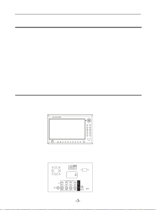
2.1 Front panel
2.2 Back panel
Page 5
!
Caution
This DVR supplies DC 12V power to 4 cameras up to 300mA maximum output per
camera. Connecting cameras exceeding the maximum power output will cause damages
to all cameras and the DVR.
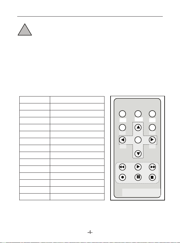
2.3 Remote Con trol
CH1 Sel ect /enlarge CH1
CH2 Sel ect /enlarge CH2
CH3 Sel ect /enlarge CH3
CH4 Sel ect /enlarge CH4
QUA D Qua d
REW Rew ind
PLA Y Pla y v ide o
FWD For war d
REC ORD Rec ord vi deo
PAU SE Pau se
STO P St op pla y
MEN U OK/E xit s ett ing me nu
OK Edi t program
UP Move cur sor up
DOW N Mov e c ursor down
Quad
CH1
CH3 CH4
Menu SEL
Remote Control
CH2
Page 6
3 Installation
3.1 Install HDD
Install HDD (“Seagate” HDD recommended)
Take out DVR HDD box when power is off. Install HDD into HDD box, connect
power supply cable and HDD cable. Install and lock HDD box back into DVR.
※Caution: Please set the HDD as Main HDD.
※Caution: Do NOT install HDD with power connected
3.2 Install camera and monitor
Four cameras and one monitor can be connected through the BNC ports in back panel
3.3 Install power supply
Please use the power supply in the DVR box.
4 DVR system process introduction
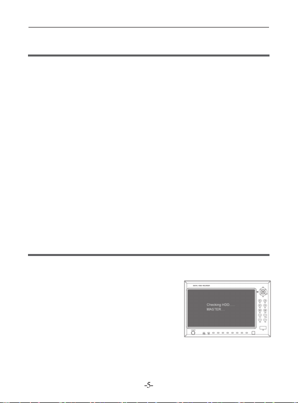
4.1 HDD test process
DVR will enter lead process immediately and test
HDD basic information when power is on.
Page 7

4.2 Recover lost data process
HDD data will be lost when power is shut
down accidentally. System will automatically
check error and return to main screen after the
test of data loss.
4.3 Video recover process
When DVR is shut down accidentally in th
video process, system will automatically recove
when the power is on again.
4.4 Enter main screen
When the DVR start, the monitor wil l
show default blue screen as “OFF” state.
Please refer to instruction 5.2 for setting.
Surveillance channel’s name will be shown
on the right bottom of the small screen. The right
bottom of main screen will show the real date and
time. If you need to enter menu setting, please press
MENU to enter main menu.
e
r
Page 8

5 DVR menu introduction
5.1 Menu Introduction
Press “MENU” to enter menu setting;
Press “ UP” and “ DOWN” to move
the cursor;
Press “ EDIT” to enter setting;
Press “MENU” to confirm and enter.
Display channel 1234
Video channel 1234
Record mode 4
Record frame rate 25
Video quality 3
Setting Record setting
System setting
HDD setting
Motion detection setting
System …………..PAL
System reset
5.2 Set display channel
System can play four channel cameras at the same time (Quad). User can set any
camera on /off in “Display” of the menu. Press “ EDIT” will change former
setting, and press “CH1”, “CH2”, “CH3”, “CH4” to select single channel in full screen
display. If the camera is not connected, system will show “OFF” in the screen.
5.3 Set video
In Video setting menu, press “ EDIT” to change original setting. User can
select “CH1”, “CH2”, “CH3”, “CH4” to set any channel’s video record.
Page 9

5.4 Set record mode
In record mode me nu, system.offers “part”, “whole” record mode.
“Part” Mode: You can record single or multi-channels with each channel
recording separately. You can select any channel for full screen display by choosing
“CH1”, “CH2”, “CH3”, “CH4”. Only in “Real time surveillance mode”, you can
press “QUAD” for 3 seconds to enlarge each channel into full screen. Each channel
will display in circle turns until you press any button to change the mode.
“Whole” mode: Four channel screen will display as a whole to be compressed.
User cannot choose single channel as full screen display.
5.5 Record frame rate setting
In “Record frame rate” menu, video display will be more fluent if the frame rate is
set higher but it will take more HDD space. 25fps, 12fps, 8fps, 6fps, 4fps, 3fps, 2fps,
1fps can be selected.
Defaulted setting is 25fps which means the system will compress 25 frames per
second.
5.6 Video quality
In “Video quality” menu, system offers 3 options: high, middle and low. Higher
image quality will take more HDD space. Record frame rate, record time and HDD
capacity would affect the length of recording time.
5.7 Record setting
In Record set ting menu, two recording
modes are available. One is time segment
recording mode and the other one is motion
detection recording mode.
“-” close recording of the time segment;
“T” time segment record mode (Default);
“M” motion detection record mode ;
Button function
[ U P ] [ DOW N ]; Move cursor.
[ EDI T ]; Select record mode.
Page 10

5.8 System setting
(1 ) Au to r eco rd
In Auto record menu, user can press [ EDI T ]
t o s et O N o r OF F . W he n set to ON ,
DVR will auto-record if there is no operation
within 5 minutes; if set to OFF, DVR will not
record until record button is pressed.
(2 ) Pa ss wo rd s witch
In the Password switch menu, user can press
[ EDIT ] to set to ON or OFF .
When set to ON , it will need password to
enter main menu and stop recording. User
can change the password. When set to OFF,
no password will be needed to enter main
menu and stop recording.
(3) Password setting
Default password: press six times CH1 key in
sequence.
In Password setting menu, all buttons can
be used as password except MENU . When
changing the password, system will require
user to enter old password first, then enter new
password. Re-enter new password again for
confirmation. Press MENU to confirm and
return. If you forget your password, please
refer to Chapter (5.11) DVR reset
(4) Color setting
User can press CH1 CH2 CH3CH4 to choose
screen . Press [ UP] [ DOWN] to move
the cursor, and press [ MENU ] to confirm the
setting and return.
Adjust range is 0-99.
Hue 52
Saturation 50
Contrast 50
Brightness 66
Hue 52
Saturation 50
Contrast 50
Brightness 66
CH1-CH4, Quad
Move Adjust Exit
1 2
3 4
Hue 52
Saturation 50
Contrast 50
Brightness 66
Hue 52
Saturation 50
Contrast 50
Brightness 66
Page 11

(5) Time setting
In Time setting menu, user can set time using
[ UP] [ DOWN] to move cursor. Press
[ EDIT] to change. Press [MENU] to
confirm the setting and return.
5.9 HDD setting
HDD rewrite:
After rewrite is set, system will not stop
recording when HDD is full. Data
recorded earlier will be replaced by new
recording.. If this function is not set, system
will stop recording when the HDD is full.
HDD capacity: Shows HDD original capacity.
HDD space: Shows HDD used space and the
occupied rate of HDD.
HDD format: Erase all data from HDD.
5.10 Motion detection setting
Motion Record time setting:
User can set continuous record time to 5,
10, 15, 20, 25, 30 second when motion is
detected.
Motion alarm time:
User can set Motion alarm to following settings
OFF – no alarm
5,10,15,20,25, 30 – alarm will remain on
within the selected time
CCNT – Alarm will be continuously on
until manually turn off
Page 12

Motion detection setting:
Channel sensitivity setting
User can press SEL to adjust motion detection sensitivity from (1-9), 1 = highest,
9 = lowest.
User can press [ UP], [ DOWN], [ REW] and [ FWD] to select
record range, and then press EDIT to confirm the setting. After channel zone setting is
finished, press [MENU] to exit, and then press [ REC] to start motion detection recording.
User can use motion detection recording only when record mode “M” is selected. Please
refer to Chapter (5.7).
5.11 System reset
User can press SEL to select System setting and DVR will reboot and go back to
factory default.
User can reset forgotten password by continuously pressing PAUSE
on the front panel for ten times; the DVR will be reset and go back to factory default.
If DVR is recording, user must first turn off the DVR, take out the HDD, then reboot
the DVR before resetting the system.
Page 13

6 Other setting
6.1 Start recording
Press REC to start recording, screen
displays as below
Only in “Part” mode, DVR can support
enlarging single channel to full screen
1. Record mark
2. Channel name
3. Record mode (whole or part)
4. Working state REC, PLAY,
FWD, REW PAUSE
5. HDD info
6. Record process: (T)Time seg
ment record mode, (M) Motion detection record mode; (-) close recording of the time
segment
7. Video date
6.2 Stop record
To stop recording, enter correct password, then press STOP .
6.3 Record time
In Part mode, estimated record time (hours) for 120G HDD.
Image quality Speed rate 30 15 7 1
High 20 58 117
NTSC
Middle 15 78 155 333 2330
Low 12 97 194 416 2913
Estimate record time (hours) of 120G HDD @ 7fps@standard quality
Image quality Speed rate 25 12 6 1
High 20 70 146
PAL
Middle 15 93 194 388 2330
Low 12 117 243 485 2913
The formula is: 120(G Byte) x1024(M Byte) x 1024 (K Byte)
15 (K byte / frame) x 7 (frame / sec.) x 60 (sec.) x 60 (min.), Estimated time = 332 Hours.
251
291
1748
1748
Page 14

7 Playback setting
Press the PLAY button on the front panel, DVR
will auto-play the latest recorded video. Press
MENU again and system will list recorded video
in their time sequence. User can use UP and
DOWN to select record and press PLAY to play
the video.
1. Record date
2. Time record: time segment record;
3. Motion detection record;
User can play back video by selecting record time
segment. In the Record time Menu, use FWD ,
UP and DOWN to move
the cursor to the target record list; Press SEL to
confirm selection, then press PLAY to play.
8 USB driver software instruction
8.1 Installation
1. Put USB driver CD that come with this
system into your computer.
2. Double click SETUP.exe file in the disk.
3. Select the right program installation path.
4. After the installation is completed, a new
program path PCVIEWER. EXE should show
under Start > Program.
8.2 Software operation instruction
Click Start – Program – PCVIEWER.exe.
Use USB cable to connect DVR and PC. The DVR should be auto detected.
Page 15

*Notice: If you computer cannot detect the
DVR, please try following steps.
(1)Close the USB program window, safely
remove the hardware, and unplug the USB cable.
(2)Press [ PLAY] on the front panel, then
connect the computer and DVR with USB cable
to try again.
Button function
1 Save frame picture 9 Channel 3 17 Fast forward
2 Save video 10 Channel 4 18 Scroll bar
3 Configuration 11 Fast Rewind 19 Software version
4 Search Record 12 Next frame 20 Audio control switches
5 Event list 13 Rewind 21 Play DVR video file
6 Channel 2 14 Pause 22 Play computer video file
7 Channel 1 15 Plays 23 Exit
8 Quad mode 16 Next frame
Page 16

Play event recorded list.
Configure DVR play/record system.
Play recorded video.
Page 17

9 System specification
N
N
N
N
N
NTSC
Parameters System specification Remark
Output
Operation system
Camera input port 4channel BNC input
Video output port 1channel BNC output
Display frame
r
ate
Video frame
rate(Quad)
Record frame
rate Each
Record mode Time segment record, motion detection record
Resolution
Video compression
format (Single channel)
HDD Up to 500G (Seagate recommended)
Record time
Record search
NTSC
TSC Max 30fps
PAL
TSC
PAL
Play
Record
Mode
Full screen YES
TSC/PAL
o Run independent
120fps
PAL 100fps
Max 25fps
Each channel=30fps signal source number
Each channel=
PAL 720 576
PAL 320 136,640 272 4: 640 224
Modified Motion------JPEG
120GHDD@7fps@common quality
(120X1024X1024k Byte) (7X15X60X60)
=
332 Hours
Time, Date, Event
25fps signal source number
TSC 720 480
320 112,640 224 1: 640 224 total
4 30fps
4 25fps
Max 30fps
Max 25fps
Low 12K Byte
Middle 15K Byte
High 20K Byte
SATA
Page 18

10 AppendixⅠ
10.1 System connection instruction
10.2 Package content (Following accessories are included in the package)
Page 19

11 Appendix Ⅱ frequently asked questions
※Question Why the DVR doesn’t start after connecting the power?
Answer: Check if the power switch in the back channel is set to ON.
※Question: Why does the DVR run slow when it starts?
Answer: ① Too much data in the HDD. DVR checks data when it starts which leads
to system starting slow.
② HDD error – System will test HDD repeatedly and will make system starts slow.
※Question: Why it keeps rebooting after the host is self-test?
Answer: ① Check the HDD. If the HDD partition is not in FAT32 format, or the HDD
has problem which will cause the host to reboot.
② Check Video Parameter setting , if the host is in PAL state but the video input is
NTSC, then the host will keep rebooting.
※Question: Why it will turn off when playing video or checking video information
during the normal routine?
Answer: ① Check HDD connection. ② Change HDD if there is a problem.
※Question: Why the video displays only in black and white?
Answer: Check if the video input, DVR host, monitor or TV format matched. If they
don’t match, please set monitor or TV format to auto detect state.
※Question: Why real time video and record data have color anamorphosis and
light distortion problem?
Answer: ① Reboot DVR, recover previous settings.
② Adjust video setting in DVR’s setting.
※Question: Why there is no display on the monitor or computer VGA?
Answer: ① Check if the power adaptor is working and the output is well connected;
② Then check if the monitor is turned on and the video cable is correctly connected;
③ Connect the power, turn on the DVR, if there’s no video on the monitor but blue
screen, then change to a corresponding channel will display the video.
※Question: Why the video has water wave and anamorphous?
Answer: ① Might be a broken Video cable or short circuit, or bad solder connection.
② Video cable can be disturbed by strong power so it cannot be put close to a strong
power cable. Please use good quality cable.
③ In this system, only simple line connected to the ground is permitted. Please connect
the host to the ground through the ground screw located at the back panel.
④ Check if the camera or monitor or the cable have aging problem.
 Loading...