

Page 1

DVR User Manual
For H.264-4-channel Digital Video Recorder
All rights reserved
Page 2

Page 3

Digital Video Recorder User Manual
CONTENTS
CHAPTER 1 Introduction..................................................................................................................................................4
1.1 DVR Introduction ..........................................................................................................................................................4
1.2 Main Features and Functions .......................................................................................................................................4
CHAPTER 2 Panel Functions...........................................................................................................................................7
2.1 Check Accessories.......................................................................................................................................................7
2.2 Front Panel & Interface Terminals.................................................................................................................................7
2.3 Rear Panel..................................................................................................................................................................10
2.4 Remote Controller Introduction...................................................................................................................................11
2.4.1 Use Remote Controller.............................................................................................................................................................................11
2.4.2 Remote Controller.....................................................................................................................................................................................12
CHAPTER 3 Basic Operation Guide..............................................................................................................................14
3.1 How to Start DVR........................................................................................................................................................14
3.2 Main Menu Setting......................................................................................................................................................14
3.2.1 Basic Configuration...................................................................................................................................................................................16
3.2.2 Live Configuration.....................................................................................................................................................................................19
3.2.3 Record Configuration................................................................................................................................................................................20
3.2.4 Alarm Configuration..................................................................................................................................................................................22
3.2.5 PTZ Configuration.....................................................................................................................................................................................27
3.2.6 User Configuration....................................................................................................................................................................................29
3.2.7 Network Configuration..............................................................................................................................................................................31
3.2.8 Manager Tools..........................................................................................................................................................................................37
3.3 Shortcut Menu ............................................................................................................................................................41
3.3.1 PTZ...........................................................................................................................................................................................................41
3.3.2 Search......................................................................................................................................................................................................42
3.3.3 Information................................................................................................................................................................................................48
3.3.4 Other.........................................................................................................................................................................................................48
CHAPTER 4 Remote Surveillance..................................................................................................................................49
4.1 Accessing DVR...........................................................................................................................................................49
4.1.1 Accessing DVR in LAN.............................................................................................................................................................................49
i
Page 4

Digital Video Recorder User Manual
4.1.2 Accessing DVR in WAN............................................................................................................................................................................50
4.2 Main Interface.............................................................................................................................................................52
4.2.1 Login.........................................................................................................................................................................................................53
4.2.2 Snap Picture.............................................................................................................................................................................................54
4.2.3 Parameter Settings...................................................................................................................................................................................54
4.2.4 Record......................................................................................................................................................................................................54
4.2.5 Camera Audio...........................................................................................................................................................................................54
4.2.6 DVR Status Panel.....................................................................................................................................................................................54
4.3 Remote Playback and Search....................................................................................................................................55
4.3.1 Remote Playback......................................................................................................................................................................................55
4.3.2 Other Functions........................................................................................................................................................................................57
4.4 Remote DVR Configuration ........................................................................................................................................60
4.4.1 Basic Configuration...................................................................................................................................................................................61
4.4.2 Live Configuration.....................................................................................................................................................................................62
4.4.3 Record Configuration................................................................................................................................................................................63
4.4.4 Alarm Configuration..................................................................................................................................................................................65
4.4.5 Network Configuration..............................................................................................................................................................................65
4.4.6 User Configuration....................................................................................................................................................................................65
4.4.7 Manage Tools...........................................................................................................................................................................................66
4.5 Remote PTZ...............................................................................................................................................................67
CHAPTER 5 Operation with Mouse ...............................................................................................................................70
5.1 Switch Channel...........................................................................................................................................................70
5.2 Enter Menu List ..........................................................................................................................................................70
5.2.1 Search......................................................................................................................................................................................................70
5.2.2 Configuration............................................................................................................................................................................................70
5.2.3 PTZ Control..............................................................................................................................................................................................70
5.2.4 Stop Record/Start Record.........................................................................................................................................................................71
5.3 Fast Reverse and Fast Forward .................................................................................................................................72
CHAPTER 6 Mobile Surveillance ...................................................................................................................................73
6.1 By Smart Phone with WinCE Operating System ........................................................................................................73
6.2 By Smart Phone with Symbian Operating System......................................................................................................76
CHAPTER 7 Frequently Asked Questions ....................................................................................................................80
Appendix A Standard & Specifications.........................................................................................................................84
ii
Page 5

Digital Video Recorder User Manual
Appendix B
Appendix C Abbreviation...............................................................................................................................................87
Record Capacity.........................................................................................................................................86
iii
Page 6

Digital Video Recorder User Manual
CHAPTER 1 Introduction
1.1 DVR Introduction
This DVR adopts the unique solution of Dual Stream technology, utilizing standard H.264 algorithm, combined currently
fashionable outline design and the latest advanced video compression for mat, with a main processor that can process
the signal of DVR recording and the signal of internet transmission simultaneously, and, more distinctively, embedding the
independent LCD monitor screen on the front panel. This solution allows that this DVR has powerful internet function of
completely remote control, good internet speed, and high-quality picture r ecording with ver y low bit rate that saves HDD
space to ensure the long-time recording.
1.2 Main Features and Functions
LIVE SURVEILLANCE
• Support channel security by hiding live display
• Display the local record state and basic information
• Two level password control: administrator and common user
• Support USB mouse and remote controller operation
• Combined LCD monitor screen with the body on the front panel
COMPRESSION FORMAT
• Standard H.264
RECORD MEDIA
• Support one SATA HDD to record
4
Page 7

Digital Video Recorder User Manual
BACKUP
• Support to backup via USB to USB flash memory
• Support to backup remotely by network client
• Two backup formats: DVR and AVI
RECORD & PLAYBACK
• Record modes: Manual operation, Sensor detection, Schedule record and Motion detection
• Support HDD recycle
• Support single channel playback
• Support four-channel playback on DVR
• Support deleting and locking recording files
• Support remote playback in Network Client through LAN or Internet
• Two record search modes: time search and event search
ALARM
• Four alarm inputs and one alarm output
PTZ CONTROL
• Support various PTZ protocols
• Support 16 PTZ presets
• Support remote PTZ control
COMMUNICATION PORT
• RS 485 communication port
NETWORK
• Support TCP/IP protocol
• Support remote DVR configuration
• Support static IP, dynamic IP (DHCP) and PPPoE
• Support DDNS: 88IP and DNS 2P
5
Page 8

Digital Video Recorder User Manual
• Real-time live surveillance, remote playback and remote backup
• Remote PTZ control and Preset setting
• Support IE browser
• Support Central Management software (short for CMS below) to manage multiple devices through Internet
• Support mobile view by phones and PDAs with WinCE or Symbian operating s ystem
6
Page 9

Digital Video Recorder User Manual
CHAPTER 2 Panel Functions
Warning: Please make sure DVR is powered off when you connect other devices with it.
2.1 Check Accessories
When you receive the machine, please check accessories, and make sure you have complete parts.
Normally, accessories include one mouse, a power cable, and some screws for installing HDD.
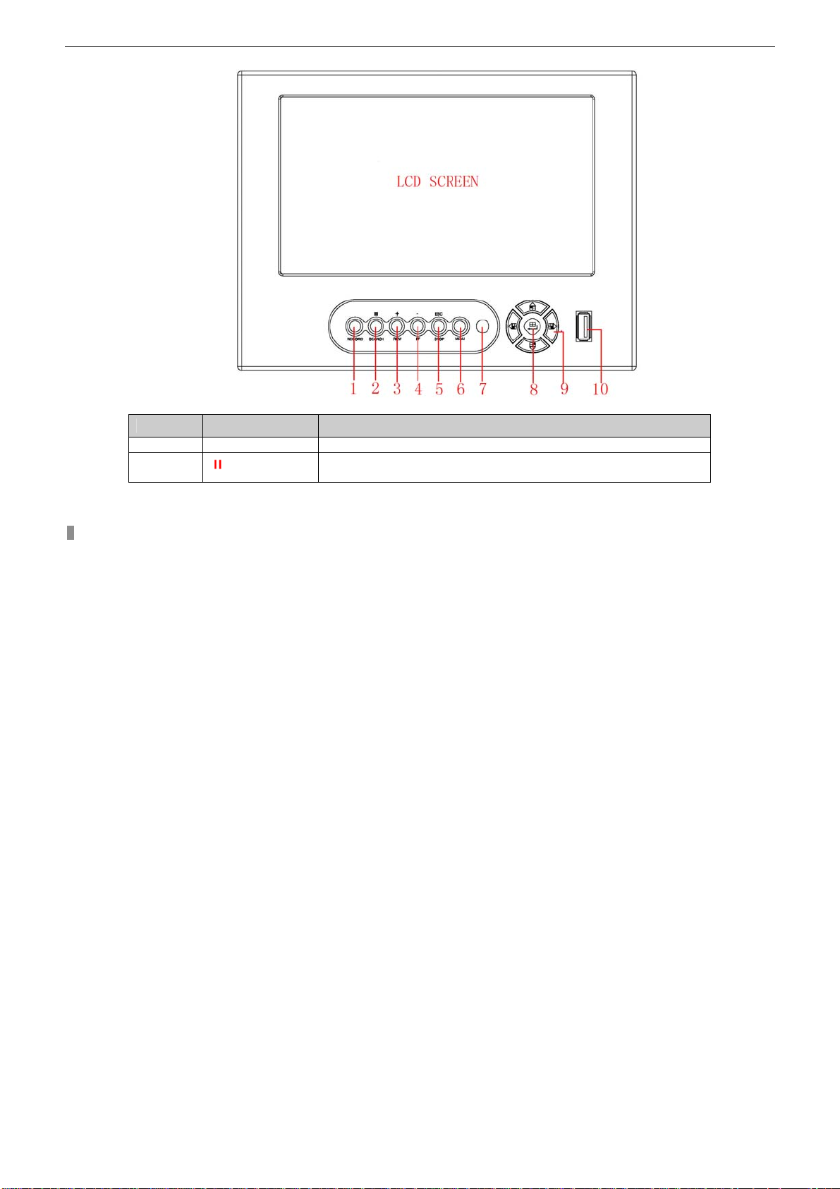
2.2 Front Panel & Interface Terminals
The front panel sketch is shown as Fig. 2.1. All buttons on the front panel are indicated in the following table. But, as
continuous upgrading of the product, its appearance might be slightly different from what you get. Please refer to the real
object.
7
Page 10
Digital Video Recorder User Manual
Fig2.1 Front Panel
Items Names Functions
1 RECORD Record manually
2
/SEARCH
1. Suspend
2. Enter search mode in live
8
Page 11
Digital Video Recorder User Manual
Items Names Functions
3 +/REW
4 -/FF
5 ESC/STOP
1. Increase the value in setup
2. Rewind
1. Decrease the value in setup
2. Fast forward
1. Exit the current interface or status
2. Quit playback mode
6 MENU Enter menu in live
7 IR Receiver For sensing remote controller
8 Enter button To confirm the choice or setup
9 Direction button Move cursor in setup
10 USB
To connect with mouse or USB devices like USB flash, USB HDD
for backup or updating firmware
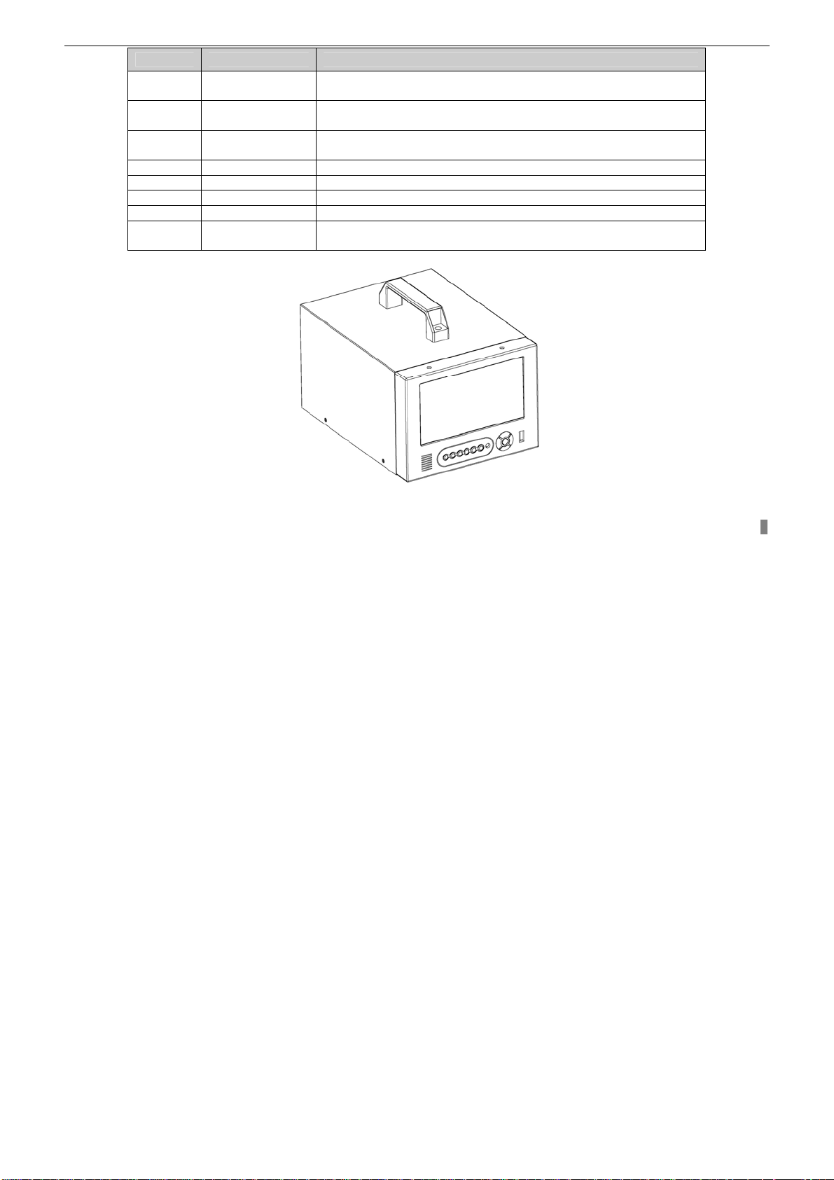
THREE-DIMENSIONAL PROFILE
9
Page 12
Digital Video Recorder User Manual
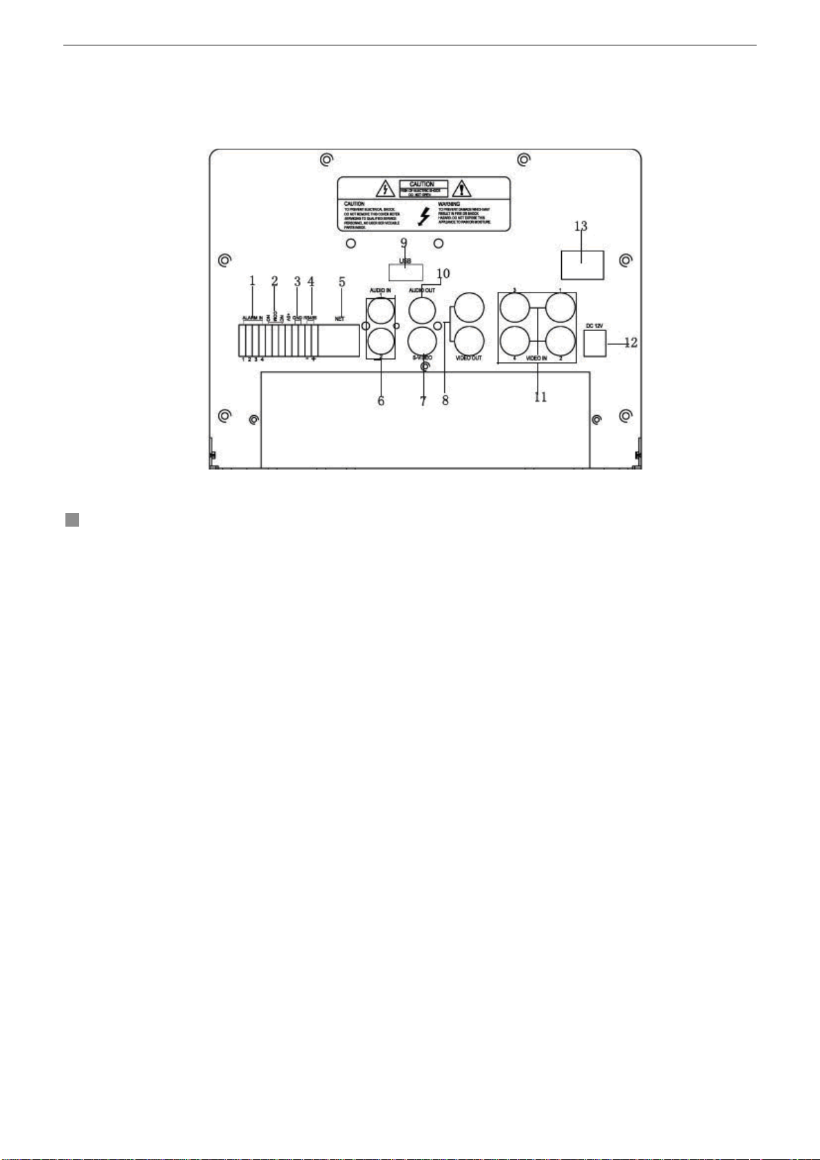
2.3 Rear Panel
For the rear panel, please refer to the real object, which may slightly different from the figure below.
The rear panel sketch and interface buttons are shown as Fig 2.2
10
Fig2.2 Back Panel
Page 13

Digital Video Recorder User Manual
Items Names Functions
1 ALARM IN Connect to external sensor 1-4
2 ALARM OUT
3 GND
4 RS485
5 NET(RJ45 PORT)
6 AUDIO IN
7 S-VIDEO
8 VIDEO OUT
9 USB PORT
10 AUDIO OUT
11 VIDEO IN
12 POWER INPUT
13 POWER SWITCH
Relay output. Connect to external alarm.
Grounding
Connected to speed domes
Connected to internet
Audio input 1-2, connect to MIC or other audio capture devices
S-Video output, connect to monitor
Connect to monitor
To connect mouse or external USB devices like USB flash, USB
HDD for backup or update firmware
Audio output, connect to the sound box
4ch Video input
DC 12V
Power on/off
2.4 Remote Controller Introduction
2.4.1 Use Remote Controller
Notice: Please note that Remote Controller is not a standard part of this DVR. Your package might exclude it.
Steps of using Remote Controller are described as below:
1. Open the battery cover of Remote Controller.
2. Put into two AAA batteries with correct order.
3. Put back the battery cover.
If the Remote Controller does not work, please check the followings:
11
Page 14
Digital Video Recorder User Manual
− Whether the battery’s anode and cathode are in the correct position
− Whether the power of the battery is run out
− Whether there is a barrier between Remote Controller and DVR
− Whether there are some signals which transmits from other devices disturbing Remote Controller
Notice: If the possibilities above are excluded, please contact with vendor to change a remote controller.
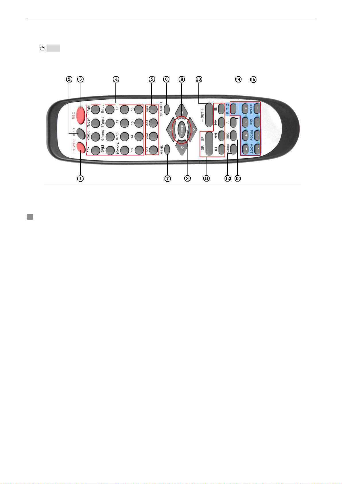
2.4.2 Remote Controller
The picture of remote controller is shown in Fig. 2.3.
Fig2.3 Remote Controller
All buttons on Remote Controller are described as table below.
12
Page 15

Digital Video Recorder User Manual
Items Names Functions
1 Power Button Shot shutdown to stop firmware running. Do it before power off.
2 INFOR Button Get information about the DVR like firmware version, HDD information
3 REC Button To record manually
Digital and letter
4
Buttons
Input digital and letters or choose camera
5 Multi Screen Button To choose multi screen display mode
6 SEARCH Button To enter search mode
7 MENU Button To enter menu
8 ENTER Button To confirm the choice or setup
9 Direction Button Move cursor in setup or pan/title PTZ
10 +/- Button To increase or decrease the value in setup
11
Playback Control
Button
To control playback, Fast forward/rewind/stop/single frame play
12 AUDIO Button To enable audio output in live mode
13 Auto Dwell Button To enter auto dwell mode
14 A Button
15 PTZ Control Button
Press the button to change input mode. Including switches among
capital letter, small letter, digital number and special symbols
To control PTZ camera
Move camera/ZOOM/FOCUS/IRIS/SPEED control
13
Page 16
Digital Video Recorder User Manual
CHAPTER 3 Basic Operation Guide
3.1 How to Start DVR
Notice: Before to power machine, please make sure the power input is eligible for local power supply.
Please observe steps below to start DVR:
STEP1 Connect DVR to AC adaptor and plug in.
STEP2 Turn on the DVR.
STEP3 Wait for DVR to initialize.
After DVR is powered on, ‘STARTING……’ appears on the screen, which indicates DVR is initializing.
When ‘WELCOME’ is displayed, you have been in live display mode. You can press "Menu" button to enter Main Menu.
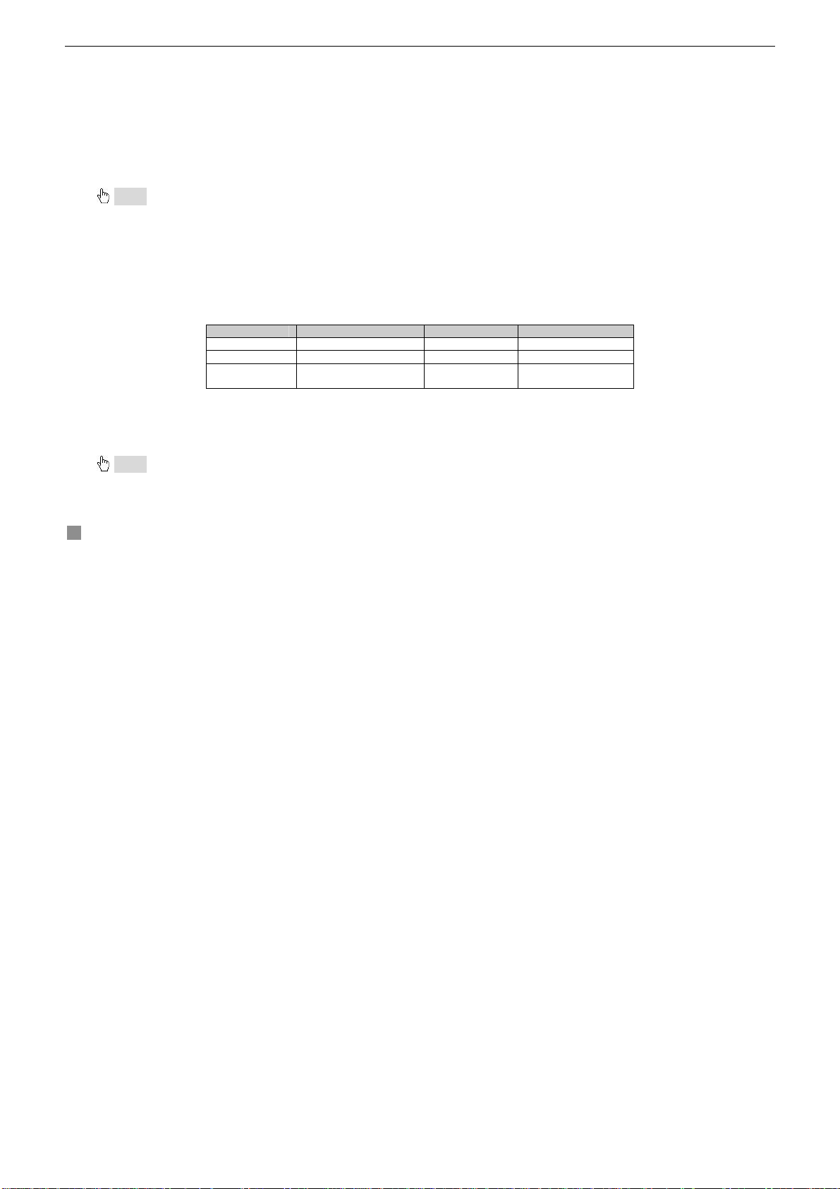
The symbols displayed on the screen are explained as following table.
Symbol Meaning Symbol Meaning
LIVE Live state REC Manual record
A Sensor record M Motion record
DISK
3.2 Main Menu Setting
There is a super administrator in the DVR. The super administrator has all setting purview. His username is "Admin", and
password is "123456". Steps of entering the Main Menu are described as below:
Notice: All of follow ing ins tructi ons, as an ex ample, are th e step s operated only by Remo te Co ntroller. For USB mouse op eration, much e asier,
please operate according to dia logue b oxes an d menu item s. If to operat e by t he front pa nel butt ons, it d oes not suppor t the co ntrol to PTZ. For all
other operations, they are same with that of the remote controller.
Ratio of using HDD
space
V-LOSS Video loss
14
Page 17

Digital Video Recorder User Manual
STEP1 Press "Menu" button, input username and pass word in the Login i nterface (as Fig. 3.1), and then you will see
the Main Menu (as Fig. 3.2).
Fig3.2 Main Menu Fig3.1 Login
STEP2 Move cursor, and the selected items will be highlighted by yellow
STEP3 Press "Enter" key to enter the sub-menu, and press "Menu" key to get back to Main Menu
The structure of the main menu is shown in Fig3.3.
15
Page 18

Digital Video Recorder User Manual
3.2.1 Basic Configuration
Basic Configuration menu is shown as Fig. 3.4.
16
Fig3.3 Structure of Main Menu
Page 19

Digital Video Recorder User Manual
Fig3.4 Basic Configuration
Fig3.5 Time Adjust
1. VIDEO FORMAT
There are two video formats: NTSC and PAL. Please select according to your standard.
2. TIME POSITION
This item is for setting up the displaying position of the time. There are three options:
• TOP: Time is displayed on top of the screen.
• BOTTOM: Time is displayed at the bottom of the screen.
• NO: Not display time on the screen
3. VGA RESOLUTION
Users can choose VGA resolution in this item.
17
Page 20

Digital Video Recorder User Manual
4. Language
There are two kinds of languages English and Spanish to be selected.
5. DVR NAME
Users can set DVR name with letters from ‘a’ to ‘z’ or numbers from ‘0’ to ‘9’.
STEP1 Press "A" button to switch the inputting mode
STEP2 Modify the DVR name.
STEP3 Press "Enter" key to confirm the operation.
6. DVR ID
DVR ID consists of three numbers.
STEP1 Move the cursor to the item.
STEP2 Press "Enter" key to modify numbers.
STEP3 Input three numbers, and then press "Enter" key to confirm the modified parameter.
STEP4 Press "OK" button to confirm the operation.
7. DATE FORMAT
There are three date formats:
• Asian Date format: YY/MM/DD
• European Date format: DD/MM/YY
• American Date format: MM/DD/YY
8. TIME ADJUSTMENT
Time Adjustment menu is shown as Fig. 3.5. Please stop recording before to adjust time.
STEP1 Move the cursor to the item.
STEP2 Modify numbers by
STEP3 Press "Enter" key to confirm the operation.
Notice: If the time that you adjust is less than the current time, the record between adjusted time and current time will be deleted
automatically.
9. BUZZER ALARM
There are seven options to choose: always( continuous buzzer), 5 seconds, 10 seconds, 30 seconds, 1 minute, 2
minutes and 4 minutes.
"+" and "-" buttons.
18
Page 21

3.2.2 Live Configuration
Live Configuration menu is shown as Fig. 3.6.
Digital Video Recorder User Manual
Fig3.6 Live Configuration
1. CHANNEL
STEP1 Move the cursor to the item.
STEP2 Press "Enter" key to select the channel
2. CHANNEL NAME
User can set the channel name with letters from ‘a’ to ‘z’ or numbers from ‘0’ to ‘9’.
STEP1 Press "A" button to switch the inputting mode.
STEP2 Input channel name.
STEP3 Press "Enter" key to confirm the operation.
3. SHOW NAME
If selecting "SHOW NAME", the camera name will be displayed in live. If unselecting "SHOW NAME", the camera name
will not display.
4. CHANNEL HIDE
If selecting "HIDE", the picture of the channel will not display in live, but it is still recording. If unselecting "HIDE", the
picture will display.
5. CHANNEL COLOR
Change the values of contrast, brightness, saturation, and hue of the picture.
19
Page 22

Digital Video Recorder User Manual
6. COPY CONFIG TO
Copy the configuration of one channel to any other selected channels. If selecting “ALL”, users can copy the configuration
to all other channels.
STEP1 Select the channel to which this ch annel will be copied, or select ALL to copy the configuration to all other
channels.
STEP2 Press "COPY" button.
STEP3 Press "Enter" key to confirm the operation.
3.2.3 Record Configuration
Record Configuration menu is shown as Fig. 3.7.
20
Fig3.7 Record Configuration
Page 23

Digital Video Recorder User Manual
Fig3.8 Schedule Setup
1. VIDEO RESOLUTION
This unit supports CIF format.
Resolutions of different video formats are: PAL: 352*288(CIF);
NTSC: 352*240(CIF)
2. RECYCLE
Ticking off "RECYCLE" means to record constantly. Once HDD is written fully , DVR will continue to record by covering the
previous record, automatically. If not ticking off "RECYCLE", record will stop once the HDD is full.
3. PRERECORD TIME
Prerecord time refers to the record time before alarm. There are two options: 5 seconds and 10 seconds.
4. TIME STAMP
If selecting, record time will be displayed on the bottom of screen at playback
5. CHANNEL
STEP1 Move the cursor to the item.
STEP2 Press "Enter" key to switch the channel and select.
6. VIDEO QUALITY
There are five options: lowest, lower, medium, higher and highest. The higher of the picture quality, the clearer of the
image is, and the larger HDD space will be occupied.
7. AUDIO
21
Page 24

Digital Video Recorder User Manual
If ticking off "AUDIO", DVR will record audio as video recording. Otherwise, it will not record audio.
Notice: • The default setting is that Audio input1 matches channel1 and Audio input2 matches channel2.
•
When playing back the record, please press "AUDIO" button to switch the sound of corresponding channel.
8. SCHEDULE RECORD
Schedule Record setting is shown as Fig. 3.8.
STEP1 Move the cursor to "SCHEDULE RECORD" option
STEP2 Tick off "SCHEDULE RECORD", and “setup” item will pop up.
STEP3 Press "Setup" to enter the Schedule Setup menu.
Press "ESC" button on the front panel to get back to upper menu.
STEP4 In the Schedule Setup menu, move the cursor.
STEP5 Press "Enter" key to set up time.
STEP6 Press "+" and "-" buttons on the front panel to modify the time.
Notice: When you use the mouse, you need roll the middle wheel to modify the time.
STEP7 Press "Enter" key to confirm the setup.
On weekday and holiday, you can select whole day or set four periods in a day to record.
9. FRAME RATE SETUP
Frame rate is the amount of recording pictures in one second. If choosing 15, the picture -recording r ate is 15 frames p er
second.
User can set frame rates for different record modes.
If the video format is NTSC, there will be five frame rates to choose: 1, 3, 7, 15 and 30. The maximum frame rate is 30.
If the video format is PAL, there will be five frame rates to choose: 1, 3, 6, 12 and 25. The maximum frame rate is 25.
10. COPY TO
It refers to copy the settings of this channel to other selected channels.
3.2.4 Alarm Configuration
Alarm Setup menu is shown as Fig. 3.9.
MOTION ALARM
Motion Alarm submenu is shown as Fig. 3.10.
22
Page 25

Digital Video Recorder User Manual
Fig3.9 Alarm Configuration
Fig3.10 Motion Alarm Configuration
1. HOLD TIME
It denotes the continual recording time after alarmed. There are two options: 1 minute an d 2 minutes. It also defines th e
interval of motion detection. If the HOLD TIME is 1 minute, the motion detected will only trigger the alarm once in 1
minute.
2. CHANNEL
STEP1 Move the cursor to the item.
STEP2 Press "Enter" key to switch the channel and select.
3. DETECTION
23
Page 26

Digital Video Recorder User Manual
Ticking off "DETECTION" means to enable motion detection, not ticking off means not to enable motion detection.
4. SENSITIVITY
It is the sensitivity of the motion detection.
The range is from ‘1’ to ‘8’. The bigger of the value, the more sensitive it is.
5. TO REC
If selecting "TO REC", DVR will record when motion event is detected. If not, DVR will not record.
6. ALARM OUT
There are two options: ALARMOUT1 and BUZZER.
• When ALARMOUT1 is selected and the sensor is triggered, DVR will give normal alarm.
• When BUZZER is selected and the sensor is triggered, DVR will give buzzer alarm.
When the alarm output is unselected, DVR will not send alarm.
7. SCHEDULE
It is the schedule of the motion detection. The default schedule is everyday. Press "SETUP” button to set motion
detection schedule.
8. AREA
STEP1 move the cursor to “setup”.
STEP2 Press "SETUP" button to enter the Area Setup submenu.
It displays the selected detection area (refer to Fig. 3.11). There are four options:
− ALL: All area will be detected such as the following picture.
− CUSTOM: Part of selected area will be detected.
− NULL: No area to detect
− BACK: Go back to Motion Alarm Configuration menu.
24
Page 27

Digital Video Recorder User Manual
Fig3.11 Detection Area Setup
Sub-steps for manually selecting the detection area are described as below:
1. In the Area Setup submenu, choose "CUSTOM" option.
2. Press "Enter" key to confirm the operation.
3. Select the part to be detected.
4. Press "Enter" key to select or cancel the part.
5. Press "Esc" button to confirm the option and exit "CUSTOM" option.
STEP3 Press "BACK" option to go back the Motion Alarm Configuration menu.
Notice: In continuous recording mode, manual record and alarm record are activated at the same time. The alarm events can be found in
Search by Event”, please refer to the account of ‘3.3.2 Search’ function in ‘3 Search by Event’.
9. COPY TO
Users can copy the settings of this channel to any other selected channel.
SENSOR ALARM
Sensor alarm submenu is shown as Fig. 3.12. Every Sensor matches one or more channels.
25
Page 28

Digital Video Recorder User Manual
Fig3.12 Sensor Alarm Configuration
1. HOLD TIME
It denotes the continual recording time after alarmed. There are two options: 1 minute an d 2 minutes. It also defines th e
interval of motion detection. If the HOLD TIME is 1 minute, the motion detected will only trigger the alarm once in 1
minute.
2. SENSOR
STEP1 Move the cursor to "SENSOR" option.
STEP2 Press "Enter" key to switch the Sensor.
3. DETECTION
It is a switch of sensor alarm. If ticking off "DETECTION", DVR will begin detecting. If not ticking off, the detection function
is disabled.
4. TYPE
Press "Enter" key to enter the sub-menu. There are two options: NO and NC.
‘NO’ means normal open. If ‘NO’ is chosen, the DVR will alarm when the alarm is in low level.
‘NC’ means normal close. If ‘NC’ is chosen, the DVR will alarm when the alarm is in high level.
5. TRIGGER RECORD
One channel can connect with one sensor. But one sensor can match one or more channels.
STEP1 Move the cursor to "TRIGGER RECORD" option.
26
Page 29

Digital Video Recorder User Manual
STEP2 Select the channel that sensors match.
STEP3 Press "Enter" key to confirm the operation.
For example, if you select the sensor named SENSOR1 and the trigger records named CAM1 and CAM2, it will record on
channel 1 and channel 2 when the SENSOR1 is triggered.
6. ALARM OUT
There are two options: ALARMOUT1 and BUZZER.
• When ALARMOUT1 is selected and the sensor is triggered, DVR will give normal alarm.
• When BUZZER is selected and the sensor is triggered, DVR will give buzzer alarm.
• When the alarm output is unselected, DVR will not send alarm.
7. SCHEDULE
It is the schedule of the sensor detection. The default schedule is everyday.
8. COPY TO
Users can copy the setting of this channel to all or any other selected channel.
OTHER ALARM
Other Alarm submenu is shown as Fig. 3.13. Other alarm includes video loss, disk full and so on.
There are two options of alarm output: ALARMOUT1 and BUZZER. Their functions are same with that in sensor alarm.
3.2.5 PTZ Configuration
PTZ Configuration menu is shown as Fig. 3.14.
Fig3.13 Other Alarm Configuration
27
Page 30

Digital Video Recorder User Manual
Fig3.14 PTZ Configuration
Fig3.15 Preset
1. CHANNEL
Switch the channel connecting to the Speed Dome.
2. BAUDRATE
There are five options of baud rate: 1200, 2400, 4800, 9600, and 19200.
3. PROTOCOL
Choose PTZ protocol. Currently it supports PELCO_D, PELCO_P, MINKING, NEON, STAR, VIDO, DSCP, VISCA and
LILIN.
4. ADDR
28
Page 31

Digital Video Recorder User Manual
Set PTZ address. Press "Enter" key and use the number key, "+" and "-" buttons to set.
5. PRESET
STEP1 Press "SET" button to enter Preset submenu shown as Fig. 3.15. There are 16 pr esetting points that can be
set in every channel.
STEP2 In Preset submenu, press "Enter" button to switch the presetting point needin g to be reset.
STEP3 Press "ADJUST" button to enter the PTZ mode.
STEP4 On the front panel, press "ZOOM", "FOCUS", "SPEED", "IRIS", "+" (MENU) and "-" (PTZ) buttons to modify
position of the presetting point.
STEP5 Press "UP", "DOWN", "RIGHT" and "LEFT" buttons to rotate the Speed Dome.
STEP6 Press "ESC" button to come back Preset menu.
STEP7 Press "SAVE" button to save the setting, and press "CANCEL" to discard the setting.
Notice: how to use the presetting point:
the number key such as "1", and the Speed Dome will move to presetting poi nt 1.
Users can use the number key to switch the pres etting point in PTZ mod e. First ly, press "PTZ" button to enter PTZ mode, then press
6. COPY TO
Users can copy the settings of this channel to all or any other selected channel.
3.2.6 User Configuration
User Configuration is shown as Fig 3.16. The default username is Admin. Administrator can add users, set users’
authorization and delete users.
29
Page 32

Digital Video Recorder User Manual
Fig3.16 User Configuration
Fig3.17 Authority Setup
1. AUTHORIZATION CHECK
If ticking off "AUTHORIZATION CHECK", all users need to input the password before entering the Main Menu.
If not ticking off "AUTHORIZATION CHECK", users can enter the system directly without password.
30
Page 33

Digital Video Recorder User Manual
2. USER
Press "Enter" key to switch to another user. Using "+” and "-" buttons change users.
3. PASSWORD
The initialized password of administrator is ‘123456’. Users can change password that is constituted by numbers from 0
to 9.
4. AUTHORIZATION
STEP1 Move the cursor to "User" option, and press "Enter" key to switch the user you want to modify authorization.
STEP2 Move the cursor to "SETUP" button on the screen.
STEP3 Press "Enter" key, Authority Setup menu (refer to Fig. 3.17) will pop up.
STEP4 In the Authority Setup menu, move the cursor to "DEFAULT".
STEP5 Press "Enter" key. The default authorization will be set.
The default authorizations include:
− Live preview, playback, backup, and Record in local system
− Live preview, playback, backup, and Record in remote network client
5. NEW USER
STEP1 Move the cursor to "ADD" button on the screen.
STEP2 Press "Enter" key, the Add User menu will display.
STEP3 Input username and password.
STEP4 Press "OK" button to confirm the option.
Username is formed by numbers or letters, with maximum 15 characters. Password is numbers between 0 and 9.
6. DELETE USER
STEP1 Move the cursor to the "DEL" button on the screen.
STEP2 Press "Enter" key to confirm the operation. When a user is deleted, the username and password won’t exist in
the system any more.
3.2.7 Network Configuration
Network Configuration menu is shown as Fig. 3.18.
31
Page 34

Digital Video Recorder User Manual
Fig3.18 Network Configuration
Fig3.19 Basic Configuration
BASIC CONFIGURATION
Basic Configuration submenu is shown as Fig. 3.19.
STEP1 Move the cursor to “Basic configuration”.
STEP2 Press "Enter" key to enter the Basic Configuration menu.
1. NET SERVER
If you select the check box and set the port number of the server, you will enable the NET SERVER.
2. NET VIDEO QUALITY
It refers to the picture quality in the remote surveillance. There are three options: low, medium and high. The higher of the
quality value, the clearer of the image is. The default level is medium.
IP CONFIGURATION
IP Configuration submenu is shown as Fig. 3.20.
32
Page 35

Digital Video Recorder User Manual
Fig3.20 IP Configuration
Fig3.21 System Information
It is DVR’s IP configuration. There are three options: STATIC, DHCP and PPPoE.
Take Static IP address as an example.
STEP1 Input IP Address, Subnet Mask and Gateway
STEP2 Press "OK" button to modify the IP Configuration menu.
If select DHCP, the IP address will be automatically assigned by local network.
After selecting DHCP, you need patience
for waiting about 30 seconds. The automatic assigned IP will be displayed on the system information window.
If selecting PPPoE, you need to input username and password when connecting to internet. If you do not know username
and password, please consult ISP.
33
Page 36

Digital Video Recorder User Manual
If you press "INFO" button, System Information menu can be displayed on the screen as long as DVR connects with the
network well (refer to Fig. 3.21).
Notice: • If the network of DVR is subjected to the following items, we recommend using Dynamic IP.
1. The local area network has DHCP server.
2. DVR can get IP address automatically from internet.
•
Before you set PPPoE, we recommend you to reboot the modem.
DDNS CONFIGURATION
DDNS Configuration submenu is shown as Fig. 3.22. The DVR supports DDNS server-‘88IP.net’. If to use DDNS, user
need to get a domain name from the ISP whose protocol is accepted by DVR.
Fig3.22 DDNS Configuration
Notice: The actual ISP list may be different for differe nt ven do rs .
Take the ‘dns2p.com’ as an example. If different from the example below, please connect with your Domain Name
Service Provider to know how to get the domain.
1. Apply the Domain Name
(1) Register in the Web
STEP1 Fill in the blank of IE address with ‘www.dns2p.com’.
STEP2 Click
to enter the website.
STEP3 Click "New User" in the right of homepage to register. For example: User ID is ‘abc’, and password is ‘123456’
(refer to Fig. 3.23).
34
Page 37

Digital Video Recorder User Manual
Fig3.23 Register Page
Fig3.24 Login Page
(2) Login
STEP1 Return to homepage after registering successfully.
STEP2 Click "Account Manager" on the right of homepage to login (refer to Fig3.24 Login Page).
STEP3 Input the username and password with the information that you have registered.
STEP4 Click "Enter" key after filling in the textbox.
(3) Domain Setup
STEP1 Click "Domain Management" on the left to set the domain (refer to Fig3.25 Domain Setup).
35
Page 38

Digital Video Recorder User Manual
Fig3.25 Domain Setup
STEP2 Input the domain in the textbox. For example, you set ‘dvr’ as the domain.
STEP3 Click "Submit" button, the system will pop up a dialog box to show that the domain is added successfully (refer
to Fig3.26 Dialog Box).
Fig3.26 Dialog Box
Notice: Its valid period is one month. If user wants to use it longer, please click "Buy Now" in the right of homepage to pay for it.
2. Setup in the DVR
(1) DOMAIN
Domain is set in ‘1 Apply the Domain Name’. According to the example above, the domain is ‘dvr.dns2p.com’.
(2) USER ID
Username is set in ‘(1) Register in the Web’. According to the example above, user ID is ‘abc’.
(3) PASSWORD
Password is set in ‘(1) Register in the Web’. According to the example above, password is ‘123456’.
Notice: If the connection fails, press the "INFO" button, the system will display: ‘DDNS NONE’. Then you need to check network and
information above and try again.
3. Application
STEP1 Connect DVR to Network Client.
STEP2 After popping up the login interface, fill in "Server" textbox with ‘ *.dns2p.com’ to visit Network Client of the
DVR.
‘*’ is the domain which is set in ‘(3) Domain Setup’. According to the example above, fill in "Server" textbox with
36
Page 39

‘ dvr.dns2p.com’.
3.2.8 Manager Tools
Manager Tools menu is shown as Fig. 3.27.
Digital Video Recorder User Manual
SHUTDOWN SYSTEM
This item is to shut down the system.
STEP1 Enter the SHUTDOWN submenu.
The following words will be shown: ‘Are you sure to shut down DVR system?’.
STEP2 Press "Enter" key to confirm the operation.
Fig3.27 Manager Tools
Fig3.28 Disk Management
37
Page 40

Digital Video Recorder User Manual
DISK MANAGEMENT
Disk Management submenu is shown as Fig. 3.28. There are two options: FORMAT and CANCEL.
1. QUICK FORMAT
To tick off this item, users can format HDD quickly.
2. FORMAT
STEP1 Select "FORMAT" button.
STEP2 Press "Enter" key, a hint will pop up: ‘Format will erase all data on this hdd! Format now? ’
STEP3 Press "OK" button to format the HDD; Press "CANCEL" or "ESC" button to cancel this operation.
Notice: • If HDD is used for the first time, system will remind user to format the HDD when the DVR started up. HDD can record as long as it is
formatted.
•
Before you format the HHD, you must stop recoding an d playing back.
•
about eight seconds to format.
Time for formatting the HDD is subjected to HDD capacity. The bigger capacity is, the longer it needs. Normally, a 40G HDD takes
SYSTEM LOG
System log submenu is shown as Fig. 3.29.
DVR will note all operations, status, and time automatically at working. User can inquire them through searching.
38
Fig3.29 Log Search
Page 41

Digital Video Recorder User Manual
Fig3.30 System Information
1. LOCAL, NET, AND OTHER
Tick off corresponding items of local operation, network client operation and other operation firstly. (Note: VLOSS is
video loss)
2. TIME
Select start time and end time of the log file.
Press "OK" button to view the event log; Press "CANCEL" or "ESC" button to cancel this operation.
The information of log files contains start time, end time and log file types. For example, 110707:092151 means
2007-7-11 9:21:51 and N-L means the LOGIN of the NET.
If there are too many log lists, user can use "PREV" button to page up and "NEXT" button to page down.
SYSTEM INFORMATION
System information submenu is shown as Fig. 3.30. It displays the information about the system, such as firmware
version, device name, DVR IP ADDRESS, Client information and so on.
Press the "INFO" button on the front panel, and it will display the system information on the screen.
39
Page 42

UPDATE FIRMWARE
Digital Video Recorder User Manual
Fig3.31 Update Firmware
Update Firmware submenu is shown as Fig. 3.31. Users can use USB disk to update the firmware.
Steps are described as below.
STEP1 Make sure the updating firmware is in the USB disk.
STEP2 Enter the menu after word-‘USB’ is displayed on the live mode.
STEP3 Move the cursor on "UPDATE" button.
STEP4 Press "Enter" key to start updating.
STEP5 After the program is upgraded, the system will restart.
LOAD DEFAULT
Fig3.33 Load Default
Load Default menu is shown as Fig. 3.33. Click YES, and it will recover the default setting at leaving factory.
IMPORT CONFIGURATION & EXPORT CONFIGURATION
This function is to help users to manage multi-DVR conveniently. When users need to set up the same parameters in
more than one DVR, they can copy one DVR’s setting to all others without setting up one by one.
EXPORT CONFIGURATION means that user copy one DVR’s parameter settings to the USB disk; and IMPORT
40
Page 43

Digital Video Recorder User Manual
CONFIGURATION means that users input the settings copied into USB disk from the first DVR to another DVR.
CLEAR ALARM OUT
This item is to clear the current alarm out, please refer to Fig. 3.34.
Fig3.34 Clear Alarm Out
3.3 Shortcut Menu
3.3.1 PTZ
Fig3.35 PTZ Mode
PTZ mode is shown as Fig. 3.35. In order to switch the channel to which the video output of the Speed Dome connects,
you may press "PTZ" button to enter the PTZ mode.
In the live view of PTZ mode, the default channel is channel 1, you can use mous e to change the channel number to
enter the corresponding channel PTZ mode.
41
Page 44

Digital Video Recorder User Manual
SPEED
STEP1 In PTZ mode, press "Speed" button.
STEP2 Press "+" and "-" buttons to change the rotational speed.
STEP3 Press "Up", "Down", "Left" and "Right" buttons to rotate the Speed Dome to certain position.
ZOOM
STEP1 In PTZ mode, press "ZOOM" button.
STEP2 Press "+" and "-" buttons to zoom in and zoom out.
FOCUS
STEP1 In PTZ mode, press "FOCUS" button.
STEP2 Press "+" and "-" buttons to control focus.
IRIS
STEP1 In PTZ mode, press "IRIS" button.
STEP2 Press "+" and "-" buttons to control little and much light of the Speed Dome.
3.3.2 Search
Press the "Search" button, there are five submenus displayed on the screen: PLAYBACK, BACKUP, DELETE and LOCK.
Data menu is shown as Fig. 3.36.
PLAYBACK
1. Select the Date
STEP1 In Data menu, move the cursor to Calendar
STEP2 Press "Enter" key to enter the Calendar submenu.
42
Fig3.36 Data
Page 45

Digital Video Recorder User Manual
Fig3.37 Calendar
Calendar submenu is shown as Fig. 3.37.
Notice: You can search the record by time search or event search. The time displayed in red has record fil e .
2. Search by Time
All records can be searched through this function. Steps of search by time as below:
STEP1 In Calendar submenu, select date.
STEP2 Press "Enter" key to enter the Playback submenu, refer to Fig. 3.38.
STEP3 Press "Enter" key to select channels.
STEP4 Select time of the day
The time in red has record file. The first line is hour, and the second line is minute.
STEP5 Select "PLAY" button.
STEP6 Press "Enter" key to play the record.
Notice: • It supports playing back in large picture mode and quad picture mode.
switch the channel.
- When you play back the record in large picture mode, you may use number buttons or "Up", "Down", "Left" and "Right" buttons to
- When you play back the record in quad picture mode, you could only see the record which was playing back as normal speed.
•
When you play back the record, you may press "INFO" button on the front panel to play or stop channel audio.
43
Page 46

Digital Video Recorder User Manual
Fig3.38 Playback
3. Search by Event
Steps of searching the event as below:
STEP1 In Playback submenu, select the camera and date. The date having recorded event is highlighted i n red.
STEP2 Move the cursor to event option.
Event search types: MOTION and SENSOR
STEP3 Press "Down" button to move the cursor to "EVENTS" button in the submenu.
STEP4 Press "Enter" key to enter the event list.
STEP5 Analyze the list information.
Take one of the event record information as an example. Meaning of the words is described as below:
− CH: Channel
− START TIME: The start time of the record.
− TYPE: The type of the event. There are two types of event: MOTION and SENSOR.
− M: Motion detection
− A: Sensor detection
− LOCK: Lock status of files.
STEP6 Choose an event record.
STEP7 Press "Enter" key to play back the record
STEP8 Press "Stop" button to get back to live display mode.
Notice: If event list is over one page, use "PREV" and "NEXT" buttons to view ne xt page.
44
Page 47

Digital Video Recorder User Manual
BACKUP&VIEW BACKUP
1. BACKUP
Select the Backup submenu in the Data menu to enter the Backup submenu shown as Fig. 3.39.
Fig3.39 Backup
(1) BACKUP MEDIA
Backup media refers to the tool for copying the record. There are five options: DVD-R, DVD-RW, DVD+R, DVD+RW and
USB disk. They connect with DVR through USB interface.
(2) BACKUP FILE
It denotes the format of backup files. This system supports AVI and DAT video formats.
• When selecting the format that DVR supports, the video format of backup files is DAT.
• Before playing the record of AVI format, it is necessary to install the decoder at first.
(3) START TIME
It is start time of recording at backup. The first line is hour, and the second line is minute. Users should choose the date
firstly and choose the time secondly.
(4) END TIME
It is end time of recording at backup. The first line is hour, and the second line is minute. Users should choose the date
firstly and choose the time secondly.
(5) CHANNEL
45
Page 48

Digital Video Recorder User Manual
It supports to select more than one channel at the same time.
(6) EVENTS
There are two options: motion and sensor. If you want to backup all records, please select "ALL".
(7) BACKUP
Before to backup, users should select BACKUP MEDIA, BACKUP FILE, CHANNEL, START TIME, END TIME and
EVENTS.
STEP1 Press "BACKUP" button, the backup information of DVR will display on the screen (refer to Fig. 3.40).
Fig3.40 Backup Information
STEP2 Press "START" button, and backup will start.
The progress of backup will be displayed on the scree n. If stopping recording at backup, its speed will be
faster.
STEP3 When the backup is over, the system will pop up a dialog box saying ‘BACKUP COMPLETELY’.
2. VIEW BACKUP
If backing up with AVI format, most media players can play directly as long as to install a decoder in advance. Installation
method: Enter "Decode" file (being created automatically by system at your backup.), then double-click
"InstallDecode.bat" file to Install successfully.
If backing up with the format DVR supports, the file player will be copied automatically in the file copying media.
DELETE
Delete submenu is shown as Fig. 3.42. The operation is shown below:
46
Page 49

Digital Video Recorder User Manual
Fig3.42 Delete
STEP1 Press "Enter" key to enter the Delete submenu.
STEP2 Press "Enter" key to select the record.
STEP3 Move the cursor to "DELETE" button and press "Enter" key, information will be given as below:
‘SOME RECORDS WILL BE DELETED, CONTINUE?’
STEP4 Select "OK" button.
STEP5 Press "Enter" key to delete this record.
LOCK/UNLOCK
Lock submenu is shown as Fig. 3. 43. Its function is to lock or unlock the record.
Fig3.43 LOCK/UNLOCK
47
Page 50

Digital Video Recorder User Manual
Use "Enter" key to change the state. If a record event is locked, it can not be deleted or covered.
3.3.3 Information
Press "INFO" button, and the information will appear on the screen, such as HDD quantity, usable rate of HDD, record
mode including manual/alarm/motion, etc.
3.3.4 Other
• In live display mode, if pressing "Up" button, it will display the first channel in full screen.
• If pressing "Down" button, it will display the second channel in full screen.
• If pressing "Left" button, it will display the third channel in full screen.
• If pressing "Right" button, it will display the fourth channel in full screen.
• If pressing "Enter" button, it will display the four-divided channel.
• If pressing "Audio" button, it will switch the voice of corresponding channel in live display mode.
48
Page 51

Digital Video Recorder User Manual
CHAPTER 4 Remote Surveillance
4.1 Accessing DVR
This system support remote surveillance through LAN or Internet.
In the remote surveillance, this DVR supports five users logging in synchronously.
Before enabling this function, it is necessary to establish a computer environment to support this unit.
Firstly, the computer should be connected with a network (LAN or Internet), do wnload, and install ActiveX controls for
remote control. As for Internet, it supports windows 2000/XP/Vista. Secondly, users should set up parameters to build up
the connection between DVR and Internet. The specific setting steps will be presented in the following parts.
4.1.1 Accessing DVR in LAN
STEP1 Input IP address, Subnet, and Gateway. If using DHCP, please enable DHCP in both of DVR and router.
STEP2 Enter “Video” submenu to set network video parameters like resolution, frame rate, etc.
STEP3 Open IE browser on a computer in the same LAN. Input the IP address of the DVR in IE textbox an d enter.
STEP4 IE will download activeX automatically. (Notice: IE property must permit to download activeX. Please refer to
Q7 in FAQ chapter) Then a window pops up and asks for user name and password.
STEP5 Input name and password correctly, and enter. It will show the picture as below.
49
Page 52

Digital Video Recorder User Manual
Figure4-1 Network Client Interface
4.1.2 Accessing DVR in WAN
When accessing DVR in WAN, users need to set safety certificate firstly.
STEP1 Double-click the IE browser icon to open the IE browser.
STEP2 Select ‘tools > Internet Options’ in menu bar, it will pop up "Internet Options" window, referred Options.
50
Page 53

Digital Video Recorder User Manual
Figure4-2 Internet Options
Figure4-3 Security Settings
51
Page 54

Digital Video Recorder User Manual
STEP3 Click "Security" option, and click "Custom Level…" in "Security level for this zone", it will pop up "Security
Settings" window as Fig. 4-3.
STEP4 In "Security Settings" window, enable all the options under ActiveX controls.
STEP5 Click "OK" to finish setting the parameters.
STEP6 Input IP of the DVR in IE textbox, then press "Enter" key.
STEP7 The Network Client interface will be displayed in IE browser as Fig. 4-1.
Notice: When the Network Client is running on VISTA operation system, you also need set relational ActiveX parameters. Steps of setting
parameters are shown as follows:
1. Open IE browser, then select ‘Internet Options > Advanced > Security’
2. Enable ‘Allow software to run or install even if the signature is invalid’ and ‘Allow active content to run in files on my computer’.
3. Click "OK" to finish the settings.
4.2 Main Interface
The function button of the remote surveillance is shown as Fig.4-4.
52
Page 55

Digital Video Recorder User Manual
Fig4.4 Main Interface
4.2.1 Login
The operation of the network client is the same as the DVR. Default username is ‘Admin’ and password ‘123456’.
STEP1 Click
button to input username and password in the popped box.
STEP2 Press "Enter" key to login.
53
Page 56

Digital Video Recorder User Manual
Notice: Click "EXIT" button to exit the system
4.2.2 Snap Picture
Snap live picture. Press
to snap the picture.
4.2.3 Parameter Settings
In Parameter Settings window, the number of pictures snapped once can be set. If selecting five, it can snap five pictures
every time by clicking "Snap Picture" button.
4.2.4 Record
STEP1 Click "DVR Record" button.
STEP2 Select "Start Record" in drag-down list to record.
STEP3 Select "Stop Record" in drag-down list to stop recording.
4.2.5 Camera Audio
There are two options: close camera audio and open camera audio. The setting steps are:
STEP1 When you are in live displ ay mode or playback mode, select a channel to display in Large Picture mode.
STEP2 Right-click the picture, and then select "Open Audio" to play the camera audio.
STEP3 Click
button to turn up or turn down the audio.
4.2.6 DVR Status Panel
Meanings of colorful indicator lights in the main interface are shown as below:
1.
Grey indicator light: Normal State
Green indicator light: Manual Record State
2.
Yellow indicator light: Motion Detection Record State
3.
Red indicator light: Sensor Alarm Record State
4.
Blue indicator light: Video Loss State
5.
54
Page 57

Digital Video Recorder User Manual
4.3 Remote Playback and Search
4.3.1 Remote Playback
Click
button in Main Interface to enter the following area which is shown as Fig4.5 Remote Playback.
Fig4.5 Remote Playback
Meanings of the functional buttons in Remote Playback window is shown as below:
1. : Play /Pause.
55
Page 58

2. : Stop.
Digital Video Recorder User Manual
3.
: Next frame This button will be valid when playback is paused.
4. You can select suitable speed for playing record in the area as Fig4.6 Multiple of Playing.
Fig4.6 Multiple of Playing
Fig4.7 Data Preview
Fig4.7 Data Preview shows the record data of different channels in corresponding time. In the figure, left side shows the
available channels. When a certain channel has been selected for playback, its background color will be highlighted an d
‘ ’ sign will appear beside the channel title.
The area of data preview at the center gives details of the record files. Different colors of the bar show different types of
records. The following are the definitions of the color bars:
Blue: Manual Record Events
Green: Schedule Record Events
Yellow: Motion Detection Record Events
Red: Sensor Alarm Record Events
The ruler on top of the bar shows 24 hours in a whole day. Right-click the ruler, it will be magnified 10 multiples, so that
users can select accurate time.
When searching for a certain section of record, please draw the bar to the right position. If necessary , right-click the bar to
see the magnified time marks to search precisely.
STEP1 Click
button to play the selected record.
When returning to live display mode after finishing remote playback, it will display ‘connect…’on the screen, and you may
click "Large Picture" or "Quad Picture" button to fresh screen to get live picture.
56
Page 59

4.3.2 Other Functions
BACKUP
Digital Video Recorder User Manual
Click
button to enter the Backup window shown as Fig4.8 Backup.
Fig4.8 Backup
There are two methods of backup: by time and by event.
1. TIME BACKUP
STEP1 Select time and record type.
STEP2 Select camera.
STEP3 Press "Browse…" button to select the folder saved backup files.
STEP4 Select cameras that you want to backup.
STEP5 Select the type of backup file.
STEP6 Click "Backup Now" button, backup will begi n.
2. EVENT BACKUP
STEP1 Select time and record type.
STEP2 Select camera.
STEP3 Press "Browse…" button to select the folder saved backup files.
STEP4 Select cameras that you want to backup.
STEP5 Select the type of backup file.
57
Page 60

Digital Video Recorder User Manual
STEP6 Click "Select Event" button to enter Select Event window shown as Fig4.9 Select Event.
1. Choose event and press ">>" button to go to backup list,
Click ">>>>" to choose all events.
2. Choose event list and press"<<" button to clear selected event; click "<<<<" button to clear all events.
STEP7 Click "OK" button to run the backup.
LOCK /UNLOCK
In this item, user can select to lock or unlock files.
STEP1 Click
button to enter Remote Lock window as Fig4.10 Remote Lock.
58
Fig4.9 Select Event
Page 61

Digital Video Recorder User Manual
Fig4.10 Remote Lock
Fig4.11 Lock Event
STEP2 Select time and record type.
STEP3 Select camera.
STEP4 Click "Select Event" button, system will find the corresponding event and pop up the LOCK EVENT window
shown as Fig4.11 Lock Event.
STEP5 Tick off the check box to change lock status.
Lock Status shows ‘√’ indicating that the event is locked, otherwise it means unlocked.
59
Page 62

Digital Video Recorder User Manual
STEP6 Click "OK" button to confirm the operation in the Lock Event interface.
4.4 Remote DVR Configuration
Click button in Main Interface to enter the following interface shown as Fig4.12 Remote DVR Configuration.
Definitions of buttons in Fig4.10 are as below:
System Configuration Live configuration
60
Fig4.12 Remote DVR Configuration
Page 63

Digital Video Recorder User Manual
Record Configuration Alarm Configuration
PTZ Configuration User Configuration
Manage Tools Return
In Remote Configuration interface, users can set all configurations remotely. Its operation is the same as that in DVR.
4.4.1 Basic Configuration
Click button in Remote Configuration and enter Basic Configuration shown as below Fig4.13 Basic
Configuration.
After changed parameters, click "OK" button, the setting will be saved and enabled on the DVR.
Fig4.13 Basic Configuration
1. Video Format
Select video format in the drag-down list. There are two video formats : PAL and NTSC.
2. Time Position
Select time position that displays on the DVR in the drag-down list.
61
Page 64

Digital Video Recorder User Manual
3. DVR Name
Change the name of DVR.
4. DVR No.
Give a number to DVR.
5. Date Format
Select the option in the drag-down list to change the date format. There are three date f ormats: YY/MM/DD, DD/MM/YY,
and MM/DD/YY.
6. Buzzer
Select the option in the drag-down list to change the time how long the buzzer will last.
4.4.2 Live Configuration
Click
button Remote Configuration, and a drag-down menu will appear. There are the Live Configuration window
and Color Settings window shown as below Fig4.14 Live Configuration and Fig4.15 C olor Settings.
Fig4.14 Live Configuration
62
Page 65

Digital Video Recorder User Manual
Fig4.15 Color Settings
LIVE CONFIGURATION
1. Channel
Select the option in the drag-down list to change the channel of camera.
2. Channel Hide
Select the check box to hide or show the picture in the live display mode.
3. Show Name
Select the check box to hide or show the name of DVR channel in the live display mode.
4. Channel Name
Input words to change the name of the channel.
COLOR SETTINGS
1. Channel
Select the option in the drag-down list to change the channel of DVR.
2. Brightness /Contrast /Saturation /Hue
Set suitable brightness, contrast, saturation, and hue for every channel by drawing the slider.
4.4.3 Record Configuration
Record Configuration window is shown as Fig4.16 Record Configuration.
63
Page 66

Digital Video Recorder User Manual
Fig4.16 Record Configuration
1. Parameter Setting
The setting is the same as ‘3.2.3 Record Configuration’ of the DVR. If you change it on Net work Client, the DVR will
change along with it.
2. Schedule Record
The default value of Schedule Record is not active.
STEP1 Click the check box of the Schedule Record, and it will be active. The default schedule time is every day.
STEP2 Click "Set Schedule" button, and Schedule Configuration window will pop up as Fig4.17 Schedule
Configuration.
64
Page 67

Digital Video Recorder User Manual
Fig4.17 Schedule Configuration
STEP3 Click "Eraser" button and click on the weekday schedule to delete the time; Click "Add" button and click on the
weekday schedule to add the time.
4.4.4 Alarm Configuration
Click
button in Remote Configuration, and a drag-down menu will appear. There are Motion Alarm window,
Sensor Alarm window and Other Alarm window. The setting is the same as ‘3.2.4 Alarm Configuration’ of the DVR. If you
change it here, the DVR will change along with it.
4.4.5 Network Configuration
Click
button to change the video quality of Network Client.
4.4.6 User Configuration
The setting of User Configuration window is the same as ‘3.2.6 User Configuration’ of the DVR. The added users in one
server can login the Server and Client.
65
Page 68

Digital Video Recorder User Manual
4.4.7 Manage Tools
Click button in Remote Configuration, and one drag-down menu will appear. There are Disk Management
window, Software Update window, Load Default window, System Information window and System Log window.
DISK MANAGEMENT
It displays the information of hard disk.
SOFTWARE UPDATE
DVR firmware can be updated remotely through Network Client software.
STEP1 Select the path of updating file.
STEP2 Click "Start" button, the updating progress will appear. The Update dialog box is sho wn as Fig4.18 Software
Update.
Fig4.18 Software Update
STEP3 After finishing update, DVR needs to reboot for running the new firmware.
LOAD DEFAULT
Load default setup.
SYSTEM INFORMATION
It displays the information of the DVR, such as version, DVR name and MAC address and so on.
SYSTEM LOG
It displays the information about operating information on the DVR.
66
Page 69

Digital Video Recorder User Manual
4.5 Remote PTZ
PARAMETERS
Before operating Remote PTZ, users should set PTZ configuration. PT Z Configuration wind ow is shown as Fi g4.19 PTZ
Configuration.
Fig4.19 PTZ Configuration
1. Channel
Select the channel in which PTZ should be control.
2. Baud Rate
Select Baud Rate of PTZ device. The default value is 9600.
3. Protocol
The communication protocol of PTZ device
4. Address
The communication address of PTZ device
Notice: Baud rate and protocol should be found in user’s manual for .PTZ camera
67
Page 70

PTZ CONTROL INTERFACE
Digital Video Recorder User Manual
Fig4.20 PTZ Control
Click button in Main Interface and enter PTZ Control interface shown as Fig4.20 PTZ Control.
Users can control PTZ devices by the function buttons on the right side of the interface. Function of the buttons is
described as below table.
Icon Description Icon Description
Rightward
Controlling the Speed Dome to swing right
Upward
Controlling the speed dome to swing up
Leftward
Controlling the speed dome to swing left.
Downward
Controlling the speed dome to swing down
68
Page 71

Digital Video Recorder User Manual
Icon Description Icon Description
FOCUS+
It sets the camera’s long focus.
ZOOM+
It sets the camera’s zoom in.
IRIS+
It sets the PTZ device’s much light.
Go to the Presetting Point
Adjust PTZ speed
It sets the rotational speed of the PTZ.
FOCUS-
It sets the camera’s short focus.
ZOOM-
It sets the camera’s zoom out.
IRISIt sets the PTZ device’s little light.
Set the Presetting Point
69
Page 72

Digital Video Recorder User Manual
CHAPTER 5 Operation with Mouse
5.1 Switch Channel
Channels can be selected and altered by Mouse. If the picture of the channel is in multi-divided mode, click on the picture
it will switch in full screen; and if in full screen, click on the picture it will change into multi-divided mode.
5.2 Enter Menu List
In the live mode, right-click on the picture can enter the menu list. There are four menus to choose: Search, Configuration,
PTZ Control and stop record/start record.
5.2.1 Search
Click "Search" menu to enter “Data” menu and select the submenu after entering the Menu list. Please refer to ‘3.3.2
Search’ and view the function of the submenu.
Right click on the picture to exit the menu.
5.2.2 Configuration
Configuration submenu is used to display the Main Menu
Click "Configuration" menu to enter the Main Menu and select the submenu after entering the Menu List. Please refer to
‘3.2 Main Menu Setting’ and view the function of the submenu.
Right click on the picture to exit the menu.
5.2.3 PTZ Control
Click "PTZ Control" menu to enter PTZ mode. The shortcut menu of PTZ is shown as Fig. 5.1
The operations of zoom-in and zoom-out, focus and inputting lightness of the Speed Dome can be realized in this
70
Page 73

interface.
Digital Video Recorder User Manual
Fig5.1 Shortcut Menu of PTZ
FOCUS
Click "FOCUS+" button to control long focus of the Speed Dome. Click "FOCUS-" button to control short focus of the
Speed Dome.
ZOOM
Click "ZOOM+" and "ZOOM-" buttons to control the Speed Dome zooming in and zooming out.
IRIS
Click "IRIS+" and "IRIS-" buttons to control little and much light of the Speed Dome.
Notice: , , and buttons are used to control the Speed Dome to swing up, right, left and down.
5.2.4 Stop Record/Start Record
This menu is for starting record or stopping record.
Stop record
Click this item, it will stop recording. At the same time, this item will change into “start record”.
71
Page 74

Digital Video Recorder User Manual
Start Record
Click this item, it will enable record and the item will change into “stop record”
5.3 Fast Rever se and Fast Forward
In playback, the main functional keys are described below:
• Click button to play back the record.
• Click button to stop playing back.
• Click button to reverse the record fast.
• Click button to forward the record fast.
72
Fig5.2 Fast Reverse and Fast Forward
Page 75

Digital Video Recorder User Manual
CHAPTER 6 Mobile Surveillance
This DVR supports mobile surveillance by smart phones and PDAs with WinCE or symbian operating system. At the
same time, it supports 3G network. Among them, Dopod D600 (WM5) and Dopod S1(WM6) have been tested and fully
certified that they worked well with the DVR.
Users should enable network service on the DVR before to make mobile surveillance. The following is instructions of two
operating systems.
Notice: It supports only live view by mobile devices and one channel at a time.
6.1 By Smart Phone with WinCE Operating System
Please use smart phones or PDAs with WinCE version supported by this unit.
STEP1 Firstly, activate the network access on mobile phone, and then run “Internet Explorer”.
STEP2 Input the DVR server’s address to connect as below.
73
Page 76

Digital Video Recorder User Manual
STEP3 Click on the software name. A dialog box will pop up.
STEP4 Click “Yes” to download and install.
STEP5 PCam will be opened after installed.
74
Page 77

Digital Video Recorder User Manual
STEP6 Input the server ’s address, ID, and password respectively in the col umns of “Server”, “User”, and “Password”.
Then click “Go” to login the DVR. It will show the picture if accessing successfully.
STEP7 Camera 1 is the default display after login. Change the camera in rolling-down menu of “Channel”.
75
Page 78

Digital Video Recorder User Manual
Notice: User name and p asswor d here a re th e same with t hat u sed on the DVR. T he def ault s are user na me “admin” and p assw ord “ 123456”.
6.2 By Smart Phone with Symbian Operating System
Please use smart phones or PDAs with symbian version supported by this unit.
STEP1 Firstly, enable the network access on mobile phone, and then run Web browser.
STEP2 Input the DVR server’s IP address in a new-built bookmark. Click this bookmark to connect with the DVR.
76
Page 79

Digital Video Recorder User Manual
STEP3 A welcome window will pop up and remind of one package required. Click “install package” to download.
STEP4 The security window will pop up after download ed and ask whether to install the package. Click YES to install.
STEP5 A Scam shortcut icon appears on the system menu after finished.
77
Page 80

Digital Video Recorder User Manual
STEP6 Run Scam program.
STEP7 Click Options--->Settings to enter login interface.
78
Page 81

Digital Video Recorder User Manual
STEP8 Input the server’s address, ID and password respectively. Then click OK to login the DVR.
STEP9 It will show the camera after access successfully.
Notice: User name and password here are the same with that used on the DVR. The defaults are user name “admin” and password
“123456”.
79
Page 82

Digital Video Recorder User Manual
CHAPTER 7 Frequently Asked Questions
Q1. Why the DVR cannot start after connected to the power?
a. The adapter has been damaged. Please change an adapter
b. The power of the adapter is not enough. Please remove the HDD to check
c. Hardware problem
Q2. The power indicator of the DVR is on, but no output. Why?
a. The power of the adapter is not enough. Please remove the HDD or change an adapter to try.
b. The video format of the DVR is different from that of the monitor.
c. Connection problem. Please check the cable and the ports of monitor and DVR.
Q3. Why are no images displayed in part or all of the channels of the DVR?
a. Connection problem. Please check the cable and the ports of camera and DVR.
b. Camera problem. Please check the cameras.
c. The video format of the DVR is different from that of the cameras. Please change DVR system format.
Q4. Cannot find HDD
a. The power of the adapter is not enough. Please change an adapter to try.
80
Page 83

Digital Video Recorder User Manual
b. Connection problem. Please check the power and data cables.
c. The HDD is damaged. Change a new one.
Q5. Cannot record
a. Not format HDD. Please format it manually first.
b. Not enable record function or incorrect setup.
c. HDD is full and not enables recycle function.
d. The HDD is damaged. Change a new one.
Q6. Mouse does not work.
a. wait for 5 seconds after mouse connected.
b. Not being identified. Plug/unplug several times.
c. The mouse is incompatible. Please change a mouse.
Q7. Cannot download ActiveX control.
a. IE browser blocks activeX. Please do setup following below.
① Open IE browser. Click Tools-----Internet Options….
81
Page 84

② select Security------Custom Level….
Digital Video Recorder User Manual
82
Page 85

Digital Video Recorder User Manual
③ Enable all the sub options under “ActiveX controls and plug-ins”
④ Then click ok to finish setup.
b. Other plug-ins or anti-virus block activeX. Please uninstall or close them.
83
Page 86

Digital Video Recorder User Manual
Appendix A Standard & Specifications
Model 4 Channel
VIDEO
Input Level
Video Standard NTSC / PAL
Video Output
Screen Split Control 1, 4Screen
Display
Speed
AUDIO
Compression PCM
Audio In/ Out 2CH/ 1CH
Input Level TBD(0.5~1.4Vp-p@20Kohm)
RECORDING
Compression H.264
Compression bit rate 64kbps-512kbps
Resolution
Mode Manual, Schedule, Motion detection, Sensor
Motion detection 16*12 detection areas can setup
HDD interface
SEARCHING
Searching Method Time, Event
REMOTE SURVEILLANCE
Monitoring Environment Self-carried LCD monitor, IE, CMS, SMART PHONE, PDA, etc.
ALARM
NTSC
PAL
NTSC Max 120FPS(CIF); 30(D1) Speed
PAL Max 100FPS(CIF); 25(D1)
NTSC 720x480 Resolution
PAL 720x576
NTSC 120FPS
PAL 100FPS
4×BNC 1.0Vp-p±10%.75Ohm
2×BNC 1.0Vp-p±10%.75Ohm,1×S-Video,1×VGA(optional item)
352(H)x240(V)(CIF); 704×480(D1)
352(H)x288(V)(CIF); 704×576(D1)
SATA×1
84
Page 87

Digital Video Recorder User Manual
Sensor Input 4 Ports
Alarm Output 1-Out (Programmable), Terminal
Motion Detection Available for Each Camera with Multi-detection Level
CONNECTOR
Video Input
Main Monitor Output
Audio Input (Mono)
Audio Output (Mono)
Sensor Input Terminal Block
Alarm Output Terminal Block
PTZ (RS-485) 2 Pins Terminal Block
Ethernet RJ-45, 10/100Mbps
USB 1.1 2 Ports
ELECTRICAL
Power Source DC 12V
Power Consumption TDP 21Watt
BACKUP
Digital Backup Network, USB 1.1
OTHERS
OS Embedded Linux operation system
Duplexer or Triplex Triplex
Control Device Front Panel, USB mouse, remote controller
PTZ control Panel, mouse remote controller or internet
BNC×4
BNC×2(Parallel), S-Video×1, VGA×1(optional)
RCA×2
RCA×1
85
Page 88

Digital Video Recorder User Manual
Appendix B Record Capacity
The following table shows the record capacity of gross four channels recorded in one hour.
Picture
Quality
Highest 352*288 100F/S 908M 352*240 120F/S 915M
Medium 352*288 100F/S 437M 352*240 120F/S 690M
Lowest 352*288 100F/S 150M 352*240 120F/S 440M
Resolution(CIF) Total frame rate
Notice: The data of the above table comes from our tests that are just used for user’s reference. Different definition and stabilization (object’s
movement) of the images will lead different results.
PAL NTSC
Capability
(M/hour)
Resolution
Total frame
rate
Capability
(G/hour)
86
Page 89

Digital Video Recorder User Manual
Appendix C Abbreviation
Words Meaning Words Meaning
L Lock HDD Hard-drive Disk
M Motion Detection A Sensor Detection
L-L The Login of Local VLoss Video Loss
PB Playback and Backup N-L The Login in or Login out of the Network
O-D Disk full of System Logs L-C Change Configuration of the DVR from the DVR
SYS The Event of System Setting or the System Reset N-C Change the Configuration of the DVR from Network
DVR Digital Video Recorder DEL Deletion Event
87
Page 90

Digital Video Recorder User Manual
88
 Loading...