

Page 1
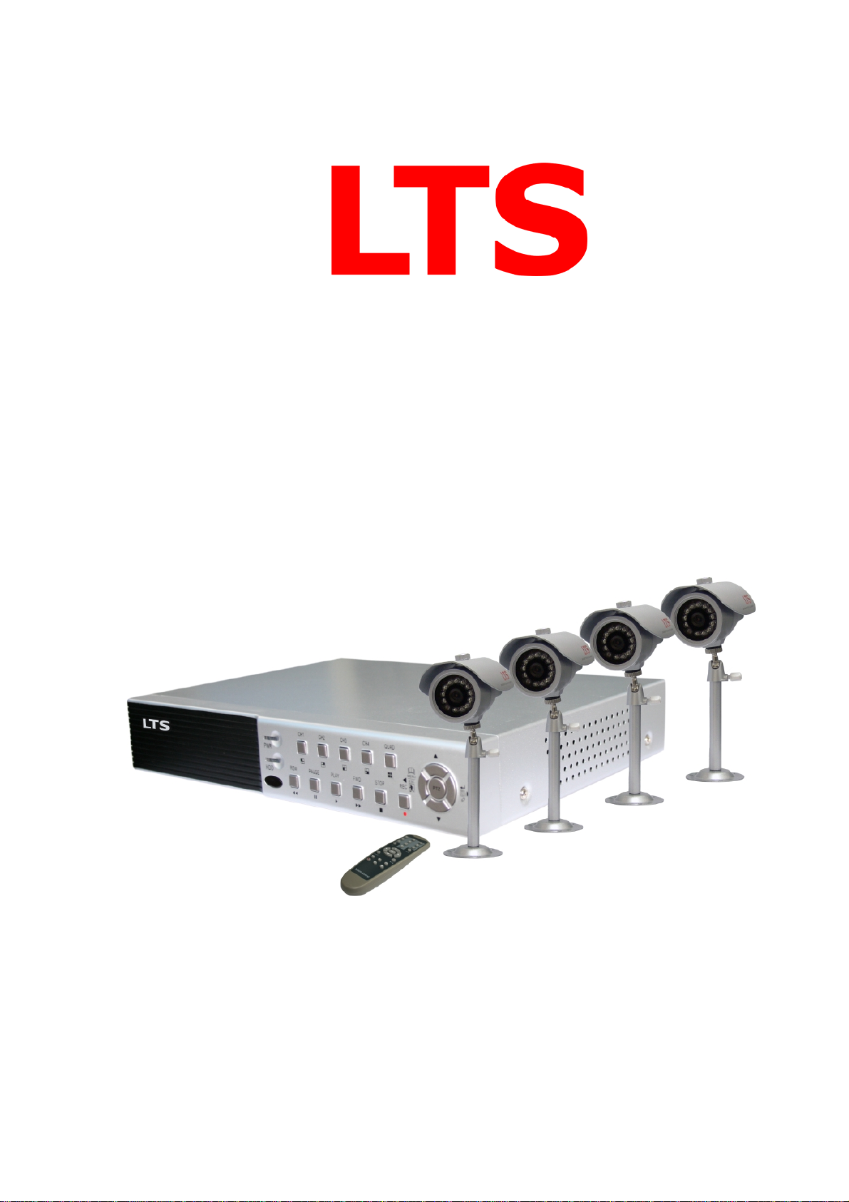
User Manual
LTD4116MKIT User Manual
0
Page 2

User Manual
CONTENTS
Chapter 1: DVR Features........................................................................................................................................3
DVR Feature ......................................................................................................................................................3
Chapter 2: Overview................................................................................................................................................3
2.1 Front Panel ...................................................................................................................................................3
2.2 Rear Panel ....................................................................................................................................................4
2.3 Remote Control ............................................................................................................................................4
Chapter 3: Installation.............................................................................................................................................5
3.1 Install Hard Disk ..........................................................................................................................................5
3.2 Connecting Camera and Monitor .................................................................................................................5
3.3 Connecting Power Supply............................................................................................................................5
Chapter 4: Starting the DVR...................................................................................................................................5
4.1 Firmware Version .........................................................................................................................................5
4.2 Detecting Installed Hard Drive.....................................................................................................................6
4.3 Format Hard Drive .......................................................................................................................................6
Chapter 5: DVR Menu System................................................................................................................................6
5.1 Navigating the Menus ..................................................................................................................................6
5.2 Menu Overview............................................................................................................................................6
5.3 Camera Setup ...............................................................................................................................................7
5.4 Record Setup ................................................................................................................................................7
5.5 Record Frame Rate.......................................................................................................................................8
5.6 Video Quality ...............................................................................................................................................8
5.7 Record Schedule...........................................................................................................................................8
5.8 Sensor Setup.................................................................................................................................................9
5.9 H/W Sensor Setup ........................................................................................................................................9
5.10 Motion Detector Setup .............................................................................................................................10
5.11 Hard Drive Setup......................................................................................................................................10
5.12 Miscellaneous Setup - Change Password................................................................................................. 11
5.13 Miscellaneous Setup - Set Time ...............................................................................................................11
5.14 Miscellaneous Setup - Hidden Channel ...................................................................................................12
5.15 Miscellaneous Setup - Audio Port Setup..................................................................................................12
5.16 Miscellaneous Setup - PTZ Setup ............................................................................................................12
5.17 Miscellaneous Setup - Image Parameters.................................................................................................13
5.18 Miscellaneous Setup - Password Enable ..................................................................................................13
5.19 Miscellaneous Setup - Keypad Tones.......................................................................................................14
5.20 Miscellaneous Setup - Sequence Dwell time ...........................................................................................14
5.21 Network Setup..........................................................................................................................................14
5.22 Language ..................................................................................................................................................17
5.23 Reset Menu...............................................................................................................................................18
5.24 NTSC/PAL Output select ....................................................................................................
Chapter
6: Record..................................................................................................................................................18
6.1 Start Recording...........................................................................................................................................18
6.2 Audio Recording ........................................................................................................................................19
6.3 Stop Recording...........................................................................................................................................19
6.4 Estimated Recording Length......................................................................................................................19
1
.....................18
Page 3

User Manual
Chapter 7: Playback...............................................................................................................................................20
Chapter 8: USB Progamming................................................................................................................................21
8.1Driver Installation: ......................................................................................................................................21
8.2 Program Interface.......................................................................................................................................21
8.3 Program Running .......................................................................................................................................22
Chapter 9: Specification ........................................................................................................................................25
9.1 DVR ...........................................................................................................................................................25
9.2 CAMERAS.................................................................................................................................................25
Chapter 10: Appendix............................................................................................................................................26
10.1 System connect sketch map..................................................................................................................26
10.2 Accessories Included With DVR..........................................................................................................26
2
Page 4
User Manual
Chapter 1: DVR Features
DVR Feature
MPEG-4 compression
4 BNC Camera Inputs - 2 BNC Video Outputs
2 channel Audio Inputs - 2 channel Audio Outputs
System Format : NTSC /PAL
Motion Detection with Sensitivity and Area Settings
Time Schedule, Alarm and Motion Triggered Recording Modes
Hard Disk Support up to 500GB
Supports PTZ Control via RS-485 Port
View and Operate over Network (Broadband Connection Required)
Built-in USB 2.0 Port for Backup to Computer
Chapter 2: Overview
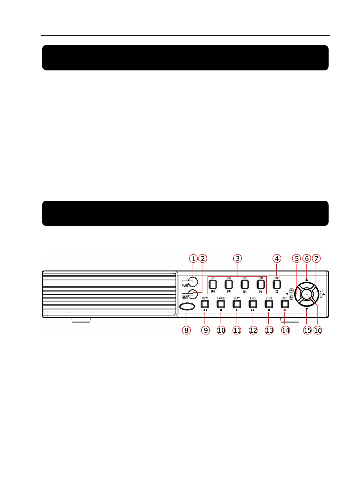
2.1 Front Panel
1. Power LED 9. REW: rewind
2. HDD LED 10. PAUSE
3. CH1-CH4 11. PLAY
4. QUAD: view all channels 12. FWD: forward
5. MENU/ESC/LEFT 13. STOP
6. UP 14. REC: record
7. SEL/EDIT/RIGHT 15. DOWN
8. IR receiver 16. PTZ: enter PTZ mode
3
Page 5
User Manual
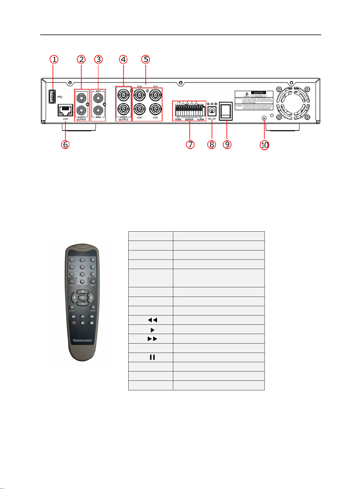
2.2 Rear Panel
1. USB port 6. LAN: Ethernet port
2.Audio outputs
7.RS485/Sensor/Alarm
3. Audio inputs 8.DC Power Input Jack
4. Video outputs 9.Power switch
5. CH1-CH4:video input 1- video input 4
2.3 Remote Control
1-4
0 Number
ALL Display all Channels
Menu Enter or Exit Menu
▲
▼
◄ / ►
SEL Select /Modify Item
Rewind
Fast Forward
●
■
Audio/Search Switch the audio channel
Mute Turn on/off audio output
10. Grounding
Channel Select 1-4
Move Up/Left
Move Down/Right
Left/ Right
Play Recording
Record
Pause
Stop Recording/Playback
4
Page 6

User Manual
Chapter 3: Installation
3.1 Install Hard Disk
NOTICE: Don’t take out HDD when DVR is running.
(
1) Remove the screws around the top cover.
(2) Remove the top cover carefully.
(3) Connect the power cord and data cable to hard disk carefully.
(4) Use the provided screws to fix hard disk on the rack inside and then replace the
top cover of the case.
3.2 Connecting Camera and Monitor
There are 4 camera inputs and 2 monitor outputs with BNC connectors (Refer to 2.2
Rear Panel).
3.3 Connecting Power Supply
Please only use the power adapter supplied with the DVR.
Chapter 4: Starting the DVR
4.1 Firmware Version
V2.3
V-MLANG
2008.5.5
After connecting the power adapter
and turning on the power button, the system
will boot-up and display the version and
released date of the DVR firmware.
5
Page 7

User Manual
4.2 Detecting Installed Hard Drive
CHECKING HDD……
MASTER [WDC WD3200AAJB-00T]
SLAVE……
4.3 Format Hard Drive
DVR will detect the installed hard drive and
display the hard drive information.
CHECKING HDD……
MASTER [WDC WD3200AAJB-00T]-NEW-DVR
FORMAT HDD CONFIRM
(SELECT) FORMAT / (MENU) CANCEL?
Chapter 5: DVR Menu System
5.1 Navigating the Menus
CAMERA SETUP
RECORD SETUP
RECORD FRAMERATE
VIDEO QUALITY NORMAL
RECORD SCHEDULE
SENSOR SETUP
HARD DRIVE SETUP
MISCELLANEOUS SETUP
NETWORK SETUP
LANGUAGE E NGLISH
RESET MENU
( )MOVE (SEL)SELECT (MENU)EXIT
MAIN MENU
When the DVR detects a new hard drive,
you will be prompted to format the hard drive
before using the DVR.
Press [SEL] to format or press [MENU]
to cancel.
(1) Press [MENU] to enter Main Menu
(2) Press [▲ or ▼] to move the cursor
(3) Press [SEL] to select/modify settings
(4) press [MENU] again to exit or go
back to previous menu.
5.2 Menu Overview
6
Page 8
User Manual
Main Menu
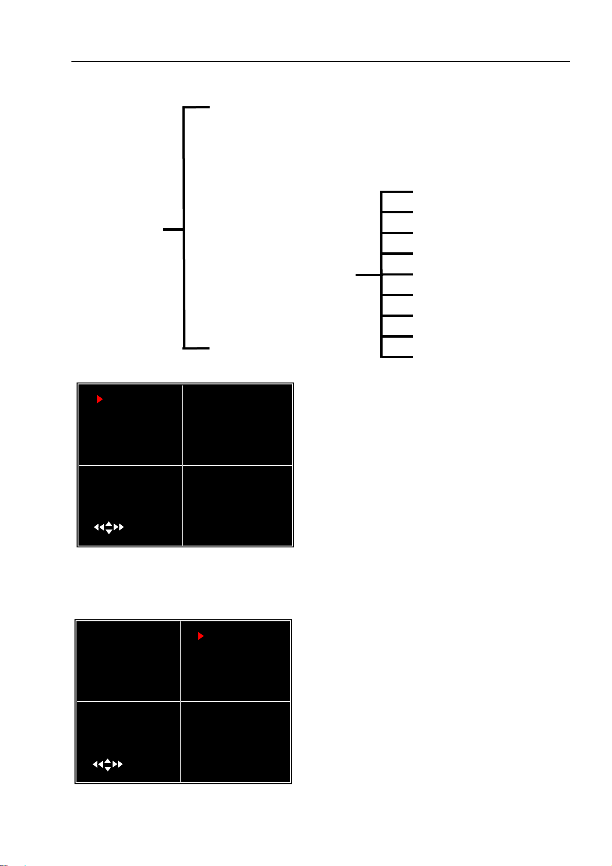
5.3 Camera Setup
Menu
Directory
Camera Setup
Record Setup
Record Frame rate
Video Quality
Record Schedul
e
Sensor Setup
Hard Drive Setup
Miscellaneous Setup
Network Setup
Language
Reset Menu
Change Password
Set Time
Hidden Channel
Audio Port Setup
PTZ Setup
Image Parameters
Password Enable
Keypad Tones
SEQ.Dwell Time
1 ON 2 ON
CAMERA SETUP
3 ON 4 ON
( )MOVE (SEL) SELECT (MENU)EXIT
Camera Setup allows you to turn
cameras on or off.
Press [▲, ▼, ◄◄ and ►►] buttons
to select a channel and then press [SEL]
to modify the setting ON or OFF.
Note:If a camera channel is set to OFF ,it will not be recorded(Refer to 6.4
Record Setup)
5.4 Record Setup
1 ON 2 NOCAM
RECORD SETUP
3 ON 4 ON
( )MOVE (SEL) SELECT (MENU)EXIT
Record Setup allows you to set up
recording channels.
Press [▲, ▼, ◄◄ and ►►] buttons to
select a channel, and then press [SEL] to
modify the setting to ON or OFF.
If a channel is disabled in Camera Setup, it
will not record and the DVR will display
“NOCAM” on screen.
7
Page 9
User Manual
5.5 Record Frame Rate
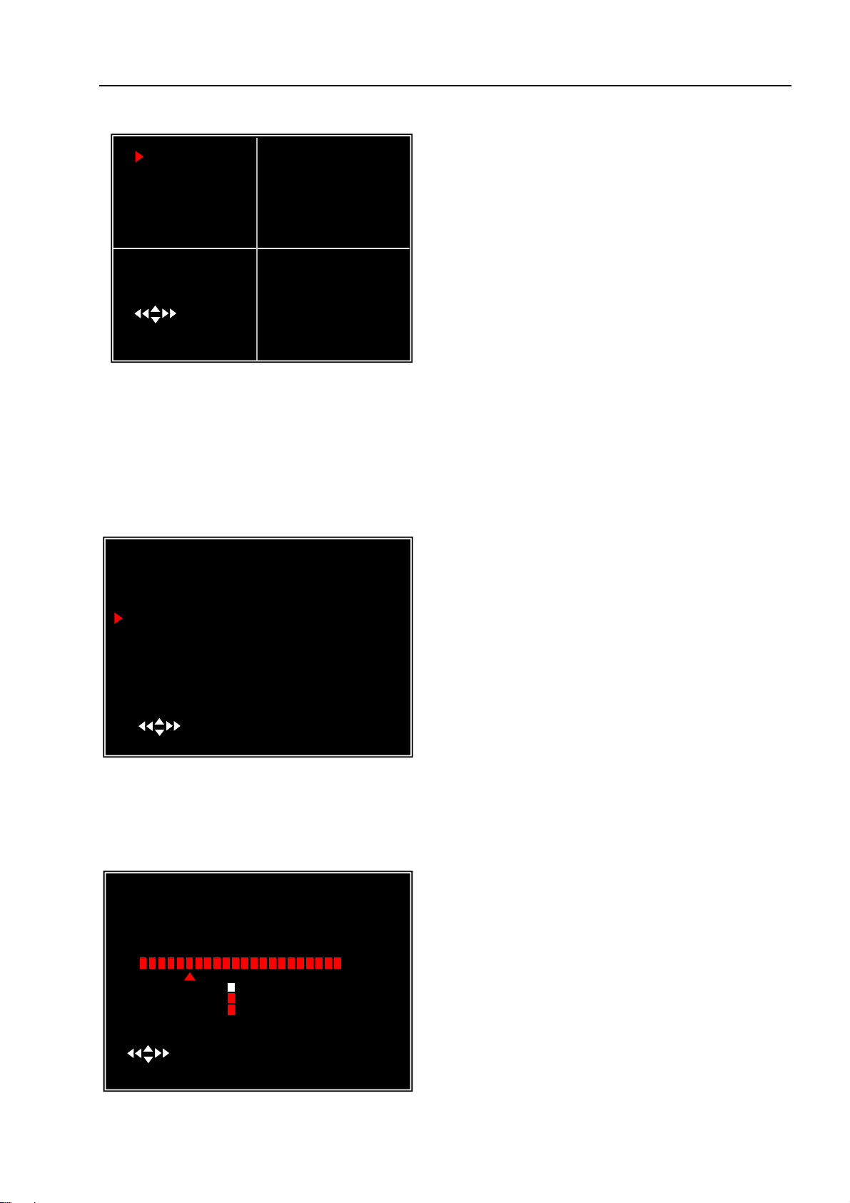
1 3FPS 2 5FPS
RECORD FRAMERATE
TOTAL 36FPS
3 25FPS 4 3FPS
( )MOVE (SEL) + ( ■ )- (MENU)EXIT
The total frame rate is 50fps (PAL) or
60fps (NTSC).
You can set the frame rate
for the channel which you selecte to record.
If the sum of the frame rate you select for
all cameras is more than 50fps (PAL)/60fps
(NTSC), the DVR will automatically adjust
the largest frame rate value to a smaller
value.
Press [▲, ▼, ◄◄ or ►►] button to select a channel, and then press [SEL] to
increase the value or press [
■STOP] to reduce the value.
Note: Higher frame rate shows smooth images, but requires more hard drive
space.
5.6 Video Quality
CAMERA SETUP
RECORD SETUP
RECORD FRAMERATE
VIDEO QUALITY NORMAL
RECORD SCHEDULE
SENSOR SETUP
HARD DRIVE SETUP
MISCELLANEOUS SETUP
NETWORK SETUP
LANGUAGE ENGLISH
RESET MENU
( )MOVE (SEL)SELECT (MENU)EXIT
MAIN MENU
V
ideo Quality has 4 different settings:
Highest, High, Normal and Low.
The higher the video quality, the better
quality of im
ages, however higher quality
images require more hard drive space.
Press
[SEL] to change the quality setting.
5.7 Record Schedule
Setting the Record Schedule allows you to customize the type of recording
depending on the time of day.
( )MOVE (SEL)SELECT (MENU)EXIT
RDCORD SCHEDULE
AM PM
0… 3… 6… 9… 0… 3…. 6… 9…
NO-RECORD
NORMAL-RECORD
S
SENSOR-RECORD
The time line indicates 24 hours of a
day based on AM/PM (0 = 12).
Press [▲, ▼, ◄◄ or ►►]
to select a time point, press [SEL] to
modify the recording mode.
8
button
Page 10

User Manual
NO-RECORD [ white]: DVR will not record during the time.
NORMAL-RECORD [
red]: DVR will record continuously.
SENSOR-RECORD [S]: DVR will record when sensor or motion is triggered.
NOTE: In order to activate the record schedule, press the [] record button when
viewing the cameras. After pressing the [] record button, if schedule is set to
“NORMAL-RECORD” , the DVR will start to record immediately; if the schedule is
set to be “SENSOR-RECORD” , the DVR will not start recording until a motion is
detected by the DVR or an installed sensor is triggered.
5.8 Sensor Setup
SENSOR SETUP
SENSORED RECORD TIME 30
ALARM ON TIME OFF
H/W SENSOR SETUP
MOTION DETECTOR SETUP
( )MOVE (SEL)SELECT (MENU)EXIT
CONT: Continuous alarm until any key is pressed
OFF: No alarm
Note: Sensored Record Time and Alarm On Time are measured in seconds
SensoredRecord Time indicates how
long the recording time is when the
motion or sensor is triggered.
Alarm On Time indicates whether the
buzzer will sound when motion is
detected.
5.9 H/W Sensor Setup
Note: Sensors and extension alarm are not included with the DVR system and may
be purchased separately.
H/W SENSOR SETUP
CHANNEL-1 TYPE:NORMAL-OPEN
CHANNEL-2 NOT INSTALLED
CHANNEL-3 NOT INSTALLED
CHANNEL-4 NOT INSTALLED
( )MOVE (SEL)SELECT (MENU)EXIT
Hardware Sensor Setup:
There are 3 different modes for sensor setting:
NOT INSTALLED, NORMAL-CLOSE and
NORMAL-OPEN. Consult the alarm
purchased for more details on which setting is
required.
9
Page 11
User Manual
5.10 Motion Detector Setup
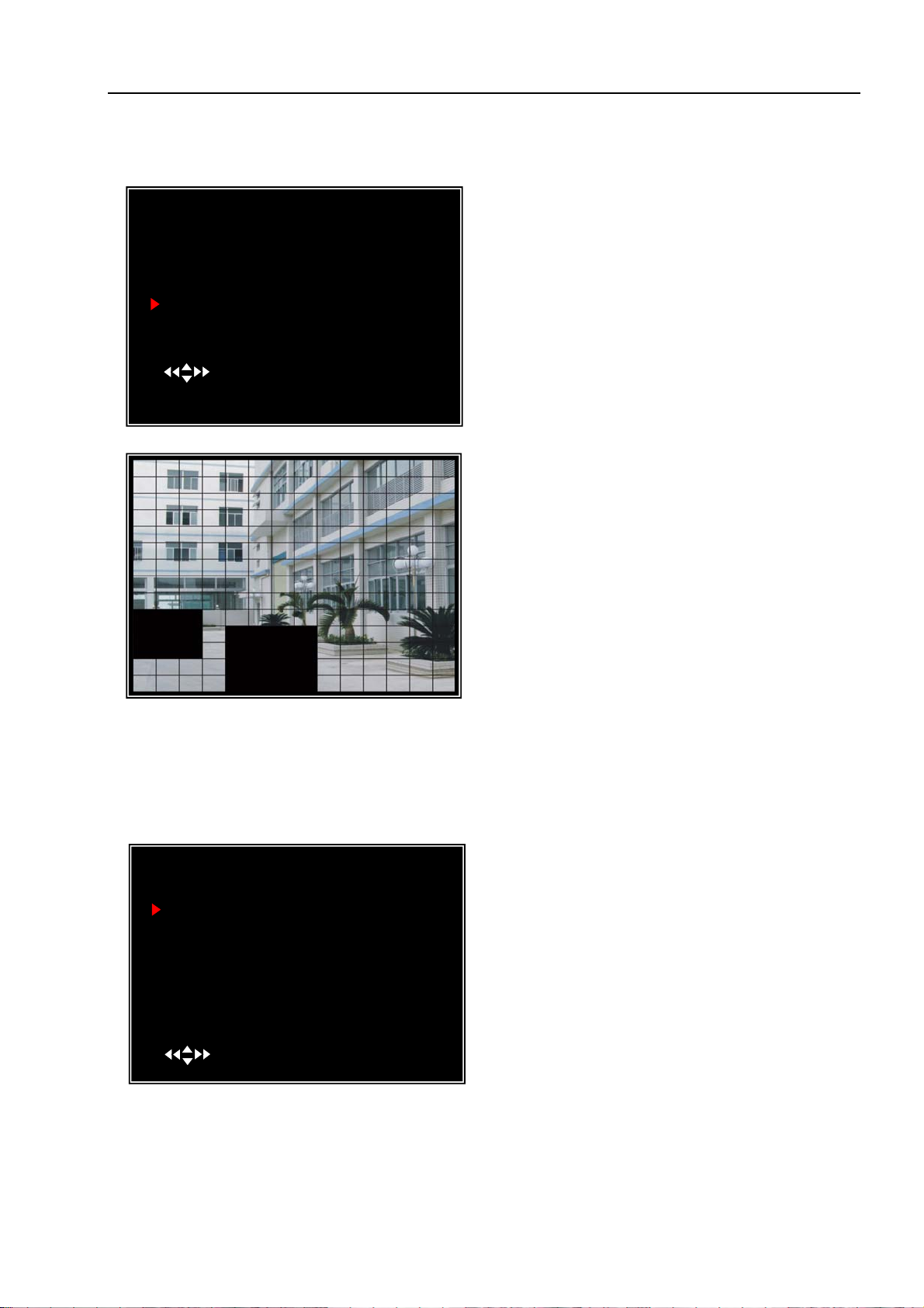
This section allows you to set up motion detection options for each camera.
MOTION DETECTOR SETUP
CH1 ON LEVEL1 AREA
CH2 ON LEVEL2 AREA
CH3 ON LEVEL2 AREA
CH4 ON LEVEL2 AREA
( )MOVE (SEL)SELECT (MENU)EXIT
Motion Detector Setup:
ON/OFF: Enable or disable motion detection
recording.
LEVEL: Sensitivity for motion detection.
There are 3 levels sensitivity:
Level 1-low,
level 3- highest
AREA: Select detectable area on the screen.
Area Selection:
Press [▲, ▼, ◄◄ or ►►] button to
select a block, and press [SEL] button to set
the block to detect motion. The area is
detectable when it is clear, the area is not
detectable when it is covert by shadow.
Press “Stop” button to disable all areas, press “Quad” button to enable all areas
5.11 Hard Drive Setup
This section will display the current hard drive status and usage options
( )MOVE (SEL)SELECT (MENU)EXIT
HDD SIZE: Indicates the total
HARD DRIVE SETUP
OVERWRITE ENABLED [ ON ]
ST3160215A
MASTER HDD SIZE 160133MB
MASTER HDD USED 124931MB 78%
MASTER HDD FORMAT
SLAVE HDD SIZE N/A
SLAVE HDD USED N/A
SLAVE HDD FORMAT
capacity of the hard drive installed in the DVR.
HDD USED: Indicates the space used in the hard disk drive for recording and the
percent used.
Overwrite Enabled:
ON: Overwrite oldest video when hard drive
is full.
OFF: Stop recording when hard drive is full.
10
Page 12

User Manual
HDD FORMAT: Will erase all video and data on the installed hard drive and make it
readable by the DVR
Note: You will be prompted for the password when formatting a hard drive. The
default password is “111111”
5.12 Miscellaneous Setup - Change Password
MISCELLANEOUS SETUP
CHANGE PASSWORD
SET TIME
HIDDEN CHANNEL
AUDIO PORT SETUP
PTZ SETUP
IMAGE PARAMETERS
PASSWORD ENABLE
KEYPAD TONES
SEQ.DWELL TIME
( )MOVE (SEL)SELECT (MENU)EXIT
CURRENT PASSWORD
NEW PASSWORD
CONFIRM PASSWORD
[ 4 ]
[ CH4 ]
[ OFF ]
[ ON ]
[ OFF]
[- - - - -]
[- - - - -]
[- - - - -]
This option allows you to change the
system password. The password m
ust be
composed with six characters.
All keys can be used as password key
except the [MENU] key, which is used to
exit.
Enter the current password first, and
then enter six characters as your new
password, repeat the new password to
confirm.
If you forget your password, please
contact technical support for assistance.
5.13 Miscellaneous Setup - Set Time
( )MOVE (SEL)SELECT (MENU)EXIT
SET TIME
2008/11/11 17:50:01
The system date an
YYYY/MM/DD and HH:MM: SS.
Press [◄◄] or [►►] button to select the
data to modify, press [SEL] to modify. Press
[MENU] to save and return to previous
menu.
11
d time format is
Page 13

User Manual
5.14 Miscellaneous Setup - Hidden Channel
MISCELLANEOUS SETUP
CHANGE PASSWORD
SET TIME
HIDDEN CHANNEL
AUDIO PORT SETUP
PTZ SETUP
IMAGE PARAMETERS
PASSWORD ENABLE
KEYPAD TONES
SEQ.DWELL TIME
( )MOVE (SEL)SELECT (MENU)EXIT
[ 4 ]
[ CH4 ]
[ OFF ]
[ ON ]
[OFF]
The system provides a function to hide a
channel in monitoring mode. The selected
channel can still be recorded while it’s hidden;
the hidden picture is viewable during playing
back.
ss [SEL] to select a channel to hide.
Pre
5.15 Miscellaneous Setup - Audio Port Setup
AUDIO PORT1-VIDEIO CHANNEL
AUDIO PORT1-RECORD
AUDIO PORT2-VIDEO CHANNEL
AUDIO PORT2-RECORD
( )MOVE (SEL)SELECT (MENU)EXIT
AUDIO PORT SETUP
[ 1 ]
[ OFF ]
[ 2 ]
[ ON ]
You can select the audio recording
function to ON or OFF, and select the
video channel that you like to record the
audio on.
5.16 Miscellaneous Setup - PTZ Setup
SPEED [4800]
PROTOCOL [PELCO-D]
CAMERA- [ 1 ] ID [ 1 ]
( )MOVE ( )CAM ID
(SEL)SELECT (MENU)EXIT
PTZ SETUP
Press [SEL] to select the camera, press[◄◄] or [►►]button to assign the ID.
Note: the ID must be unique.
SPEED: Set the baud rate (2400,4800,
9600,19200,38400) to match your speed
dome.
PROTOCOL: Supports “PELCO-D” and
“PELCO-P”. Select the protocol
according to your speed dome’s protocol.
CAM
ERA: select the camera channel
which is connected with the speed dome.
12
Page 14
User Manual
5.17 Miscellaneous Setup - Image Parameters
MISCELLANEOUS SETUP
CHANGE PASSWORD
SET TIME
HIDDEN CHANNEL
AUDIO PORT SETUP
PTZ SETUP
IMAGE PARAMETERS
PASSWORD ENABLE
KEYPAD TONES
SEQ.DWELL TIME
( )MOVE (SEL)SELECT (MENU)EXIT
[ 1 ]
[ CH4 ]
[ OFF ]
[ ON ]
[OFF]
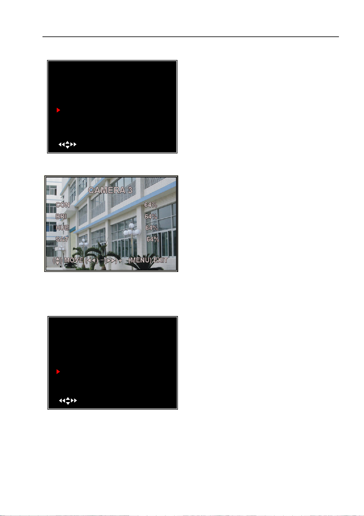
You can adjust the image parameters
according to your needs.
Move the cursor to this selection and
press [◄◄] or [►►] button to select a
channel you want to adjust, then press
[SEL] button to edit parameters.
CON: Contrast
BRI: Brightness
HUE: Hue
SAT: Saturation
Press [▲] or [▼] to select the item,
and then press [◄◄] and [►►] buttons
to adjust the value.
5.18 Miscellaneous Setup - Password Enable
MISCELLANEOUS SETUP
CHANGE PASSWORD
SET TIME
HIDDEN CHANNEL
AUDIO PORT SETUP
PTZ SETUP
IMAGE PARAMETERS
PASSWORD ENABLE
KEYPAD TONES
SEQ.DWELL TIME
( )MOVE (SEL)SELECT (MENU)EXIT
[ 1 ]
[ CH4 ]
[ OFF ]
[ ON ]
[OFF]
The password will be required to
control the DVR when this option is set to
“ON”, and the password is not required
when this option is set to “OFF”.
13
Page 15

User Manual
5.19 Miscellaneous Setup - Keypad Tones
MISCELLANEOUS SETUP
CHANGE PASSWORD
SET TIME
HIDDEN CHANNEL
AUDIO PORT SETUP
PTZ SETUP
IMAGE PARAMETERS
PASSWORD ENABLE
KEYPAD TONES
SEQ.DWELL TIME
( )MOVE (SEL)SELECT (MENU)EXIT
[ 4 ]
[ CH4 ]
[ OFF ]
[ ON ]
[OFF]
This function allows you to enable
/disable buzzer sound when pressing a
button. Press [SEL] to select ON or
OFF.
5.20 Miscellaneous Setup - Sequence Dwell time
MISCELLANEOUS SETUP
CHANGE PASSWORD
SET TIME
HIDDEN CHANNEL
AUDIO PORT SETUP
PTZ SETUP
IMAGE PARAMETERS
PASSWORD ENABLE
KEYPAD TONES
SEQ.DWELL TIME
( )MOVE (SEL)SELECT (MENU)EXIT
[ 4 ]
[ CH4 ]
[ OFF ]
[ ON ]
[OFF]
This function allows you to set the
dwell time for each camera when you
enabe the auto sequence display function.
Press [◄◄] and [►►] buttons to
adjust the value.
After setting, press [
] to turn on
auto-sequence display function and press[ ] again to turn off this function in
preview mode
5.21 Network Setup
Network Setup allows you to prepare the DVR for viewing over the internet or
local network.
MAC ADDRESS
IP ALLOCA TION
IP ADDRESS
SUBNET MASK
GATEWAY
DNS1 ADDRESS
DNS2 ADDRESS
HTTP PORT
USER SETUP
DDNS SETUP
(HTTP PORT) 80, 1024-49151
( )MOVE (SEL)SELECT (MENU)EXIT
NETWORK SETUP
<00:11:22:33:44:55>
[STATIC]
[192.168.1.100]
[255.255.255.0]
[192.168.1.1]
[0.0.0.0]
[0.0.0.0]
[ 80]
MAC ADDRESS: In a local area network(LAN),the
MAC (Media Access Control) address is your
computer’s unique hardware identity code(On an
Ethernet LAN,it is the same as your Ethernet
address).When you are connected to the Internet
from your computer (or host as the Internet protocol thinks of it ) a corresponding table relates your
IP address to your computer’s physical (MAC)
address on the LAN.
14
Page 16

User Manual
IMPORTANT: This setting should only be changed if multiple DVRs are being setup on the same
network and the first code “00” must not to be changed.
MAC ADDRESS
IP ALLOCA TION
IP ADDRESS
SUBNET MASK
GATEWAY
DNS1 ADDRESS
DNS2 ADDRESS
HTTP PORT
USER SETUP
DDNS SETUP
(HTTP PORT) 80, 1024-49151
( )MOVE (SEL)SELECT (MENU)EXIT
NETWORK SETUP
<00:11:22:33:44:55>
[STATIC]
[192.168.1.100]
[255.255.255.0]
[192.168.1.1]
[0.0.0.0]
[0.0.0.0]
[ 80]
MAC ADDRESS
IP ALLOCA TION
IP ADDRESS
SUBNET MASK
GATEWAY
DNS1 ADDRESS
DNS2 ADDRESS
HTTP PORT
USER SETUP
DDNS SETUP
(HTTP PORT) 80, 1024-49151
( )MOVE (SEL)SELECT (MENU)EXIT
NETWORK SETUP
<00:11:22:33:44:55>
[STATIC]
[192.168.1.100]
[255.255.255.0]
[192.168.1.1]
[0.0.0.0]
[0.0.0.0]
[ 80]
MAC ADDRESS
IP ALLOCA TION
IP ADDRESS
SUBNET MASK
GATEWAY
DNS1 ADDRESS
DNS2 ADDRESS
HTTP PORT
USER SETUP
DDNS SETUP
(HTTP PORT) 80, 1024-49151
( )MOVE (SEL)SELECT (MENU)EXIT
NETWORK SETUP
<00:11:22:33:44:55>
[STATIC]
[192.168.1.100]
[255.255.255.0]
[192.168.1.1]
[0.0.0.0]
[0.0.0.0]
[ 80]
MAC ADDRESS
IP ALLOCA TION
IP ADDRESS
SUBNET MASK
GATEWAY
DNS1 ADDRESS
DNS2 ADDRESS
HTTP PORT
USER SETUP
DDNS SETUP
(HTTP PORT) 80, 1024-49151
( )MOVE (SEL)SELECT (MENU)EXIT
NETWORK SETUP
<00:11:22:33:44:55>
[STATIC]
[192.168.1.100]
[255.255.255.0]
[192.168.1.1]
[0.0.0.0]
[0.0.0.0]
[ 80]
IP ALLOCATION: DVR supports DHCP and
Static IP modes. If your modem/router supports
DHCP function, you can use DHCP mode. When
using STATIC mode, you will be required to setup
your IP settings manually.
Note: After setting the DVR to DHCP mode restart
the unit.
IP Address: In a local network, the IP address is
a unique designated address for your DVR
recognized by your router. Ensure this number is
within the range usable by your modem/router.
Use the UP “▲” and DOWN “▼” buttons to
move the cursor and use the “SELECT” button
to change the numbers. Once you have finished
the changes restart your DVR.
SUBNET MASK: Subnet Mask is used to
determine what subnet an IP address belongs to.
A number that is used to identify a sub network
so that IP addresses can be recognized on a local
area network.Consult your modem/router for
your LAN’s subnet mask.
GATEWAY: Set this number to the gateway
set by your modem/router.
15
Page 17

User Manual
[
]
NOTE: To adjust the IP ADDRESS,SUBNET MASK and GATEWAY value, only when the
[STATIC] mode is being selected.
MAC ADDRESS
IP ALLOCA TION
IP ADDRESS
SUBNET MASK
GATEWAY
DNS1 ADDRESS
DNS2 ADDRESS
HTTP PORT
USER SETUP
DDNS SETUP
(HTTP PORT) 80, 1024-49151
( )MOVE (SEL)SELECT (MENU)EXIT
NETWORK SETUP
<00:11:22:33:44:55>
[STATIC]
[192.168.1.100]
[255.255.255.0]
[192.168.1.1]
[0.0.0.0]
[0.0.0.0]
[ 80]
MAC ADDRESS
IP ALLOCA TION
IP ADDRESS
SUBNET MASK
GATEWAY
DNS1 ADDRESS
DNS2 ADDRESS
HTTP PORT
USER SETUP
DDNS SETUP
(HTTP PORT) 80, 1024-49151
( )MOVE (SEL)SELECT (MENU)EXIT
NETWORK SETUP
<00:11:22:33:44:55>
[STATIC]
[192.168.1.100]
[255.255.255.0]
[192.168.1.1]
[0.0.0.0]
[0.0.0.0]
[ 80]
( )MOVE (SEL)SELECT (MENU)EXIT
USER SETUP
ADMIN ID …… [admin ]
AD MIN PA SSW ORD [111111]
USER ID
USER PASSWORD
[ ]
[ ]
DOMAIN NAME
DDNS PROVIDER
DDNS USER NAME
DDNS PASSWORD
( )MOVE (SEL)SELECT (MENU)EXIT
DDNS SETUP
[WWW.DynDNS.com ]
[ ]
[
]
DNS ADDRESS: This code should be provided
by your local ISP.
HTTP PORT: This port number is used to
communicate with PC Client. The default value is
80(Can be changed from 1024 to 49151)
USER SETUP: When accessing the DVR
from a remote location you will be prompted
for a login and password. The default is
“admin” for full administrator rights. Set “User
ID” and password to setup a user with limited
rights to prevent tampering.
DDNS SETUP: If you require an external
service to maintain a dynamic IP address enter
the user information here.
16
Page 18
User Manual
LAN-DVR Connection
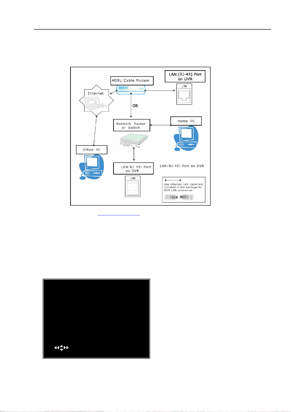
See the diagram below for steps to connect your DVR to a local area network or the internet.
For remote monitoring from your computer,you must have a LAN connection available or
broadband Internet access.
You need to register a www.dyndns.com to get a free account .After registration,you will have
a username and password. You can also register your domain name on the website. Please refer to
Chapter 5 “Network Setup” for more details. There you will learn how to input the Dyndns
username,password,and domain name. You can log in from anywhere by using Internet Explorer
and entering your DVR’s domain name.
z
5.22 Language
MAIN MENU
CAMERA SETUP
RECORD SETUP
FRAMERATE
RECORD
VIDEO QUALITY NORMAL
RECORD SCHEDULE
SETUP
SENSOR
HARD DRIVE SETUP
M
ISCELLANEOUS SETUP
NETWORK SETUP
ANGUAGE E NGLISH
L
RESET MENU
( )MOVE (SEL)SELECT (MENU)EXIT
You can change the OSD language
from the default English to other
languages.
17
[WWW.DynDNS.com ]
[ ]
Page 19
User Manual
5.23 Reset Menu
If you select this item, the system will restore all your settings to factory default
values. You need to enter your password to reset the menu.
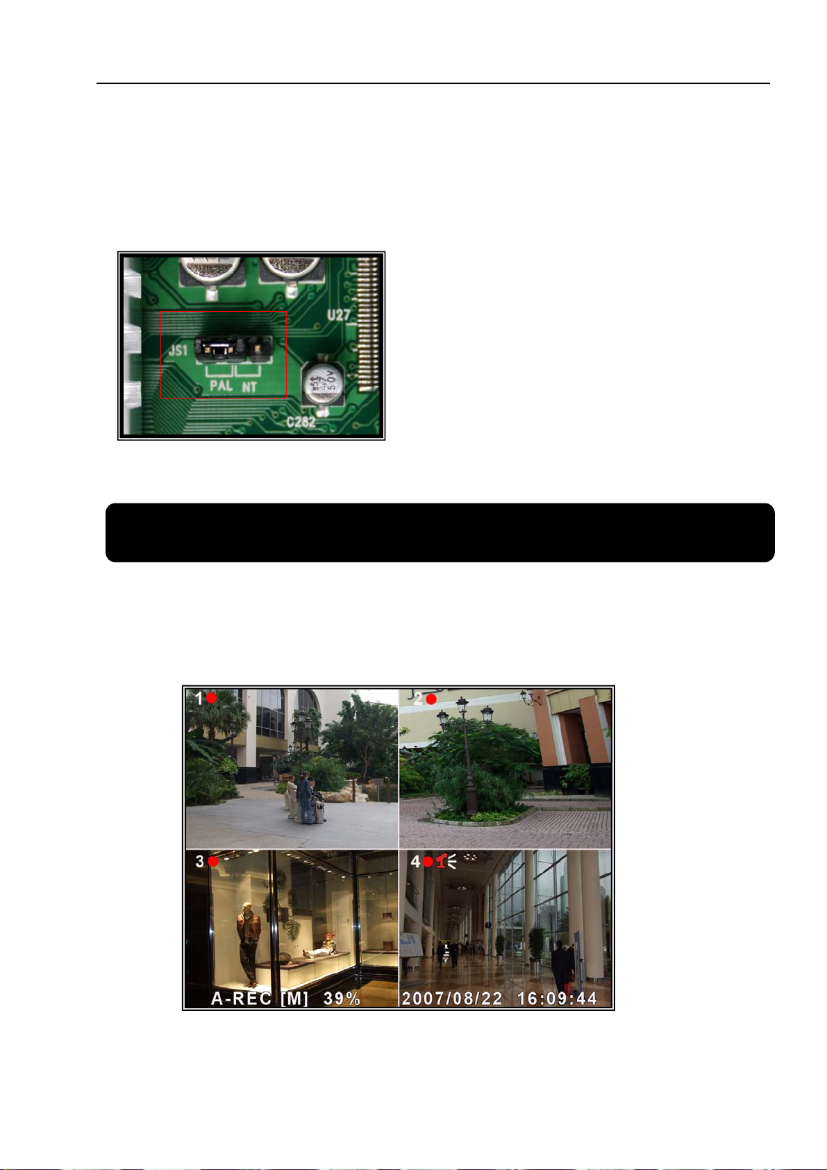
5.24 NTSC/PAL Output select
Change the jumper JS1 to select NTSC or
PAL video output format according to the
silkscreen on the PCB.
Chapter 6: Record
6.1 Start Recording
Press [●] record button to start recording according to the record schedule you
have set. System will display some information on screen.
[
●]: the red pot next to the channel name indicates that the channel is being
18
Page 20

User Manual
recorded.
[A-REC]: indicates the current record schedule is set to NORMAL-RECORD mode.
[S-REC]: indicates the current record schedule is set to SENSOR-RECORD mode.
[N-REC]: indicates the current record schedule is set to NO-RECORD mode.
[39%]: indicates the percentage of hard disk space used.
[M]: HDD info ([M] Master Hard Disk)
6.2 Audio Recording
[ ]: indicates this video channel is bundled with an audio port, and the audio
output is on.
[
]: indicates the audio output is off.
[
]: indicates the audio is being recorded and the audio output is on.
you could press [DOWN] button on front panel to be mute mode for audio output.
The audio input can be still recorded while the output is mute.And you could press
[UP] button to switch one of the two audio inputs to live output
6.3 Stop Recording
Press [■] stop button will stop recording. If password protection function is
enabled, system will prompt you to input password. Only correct password can stop
recording process.
6.4 Estimated Recording Length
Estimated rec ord time based on 160GB HDD
Standard Quality 60fps 48fps 32fps 16fps 1fps
Highest 62 78 116 232 3720
NTSC
Standard Quality 50fps 36fps 24fps 12fps 1fps
PAL
High 88 110 165 330 5280
Normal 107 134 201 401 6420
Lower 120 150 225 450 7200
Highest 64 89 133 267 3200
High 90 125 188 375 4500
Normal 110 153 229 458 5500
Lower 123 171 256 513 6150
Unit: Hour
19
Page 21

User Manual
Chapter 7: Playback
In preview mode, pressing the [►] PLAY button goes into PLAYBACK mode.
The newest record event will be played.
SEARCH VIDEO
DISK:MASTER SLAVE [NONE]
08/09/19 11:16:31 - 08/09/19 15:05:48
TYPE:EVENT TIME
PLAY:EVENTS
00006 T 2008/09/19 15:07:40
00006 T 2008/09/19 14:07:40
00006 T 2008/09/19 13:07:40
00006 T 2008/09/19 12:07:40
00006 T 2008/09/19 11:07:40
00006 T 2008/09/19 10:07:40
00006 T 2008/09/19 09:07:40
( )MOVE (SEL)SELECT
( )PLAY (MENU)PREV MENU
SEARCH VIDEO
DISK:MASTER SLAVE [NONE]
08/09/19 11:16:31 - 08/09/19 15:05:48
TYPE:EVENT TIME
PLAY:00006 T 2008/09/19 15:07:40
( )MOVE (SEL)SELECT
( )PLAY (MENU)PREV MENU
Press the [MENU] button during in
YBACK mode,then the system will list
PLA
all the recorded events. The latest record will
be on top of the list. Press the [▲]or [▼]
button to selecte the event and then press
[► to play the event.
]
Another way to search video is directly input
time period. Press the [MENU] button then
use[◄◄] or [►►] button to select the TIME
search mode. Use [SEL] button to edit time
value, press [►] to play the video. If the time
you selected has no record event, it will
indicates “NO EVENTS” on the screen when
you press [►]
20
Page 22
User Manual
Chapter 8: USB Progamming
8.1Driver Installation:
(1) Insert driver CD in your CD-ROM Drive.
(2) Open CD directory.
(3) Double click the install applications.
(4) Follow the setup wizard to finish the installation.
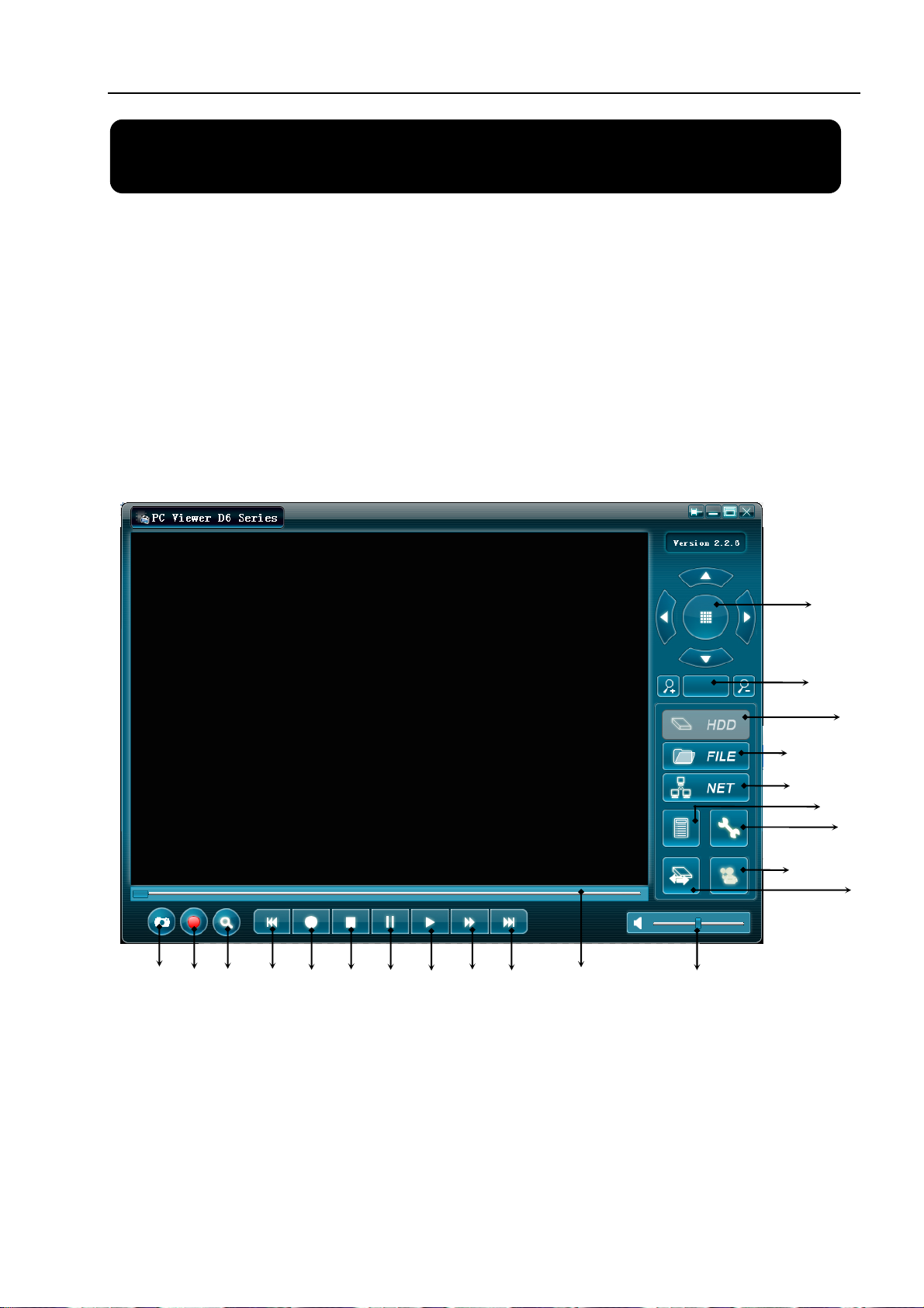
8.2 Program Interface
Button functions:
12
11
10
13
14 15
16 18
17
19
20
21
1
2
3
4
5
6
7
8
9
21
Page 23
User Manual
1.PTZ Control 12. Time Search
2.Zoom in,Zoom Out 13.Back One Frame
3.HDD Play Mode 14.Record
4.File Play Mode 15.Stop
5.Net Play Mode 16. Pause
6.Event List 17. Play
7.Control Panel 18.Fast Forward
8.Remote DVR Control 19.Forward One Frame
9.Change Storage Device 20.Playback Slider
10.Capture Image 21.Audio Slider
11.Convert Streams to AVI file
8.3 Program Running
8.3.1 HDD play mode
System will detect the HDD automatically when you connect the USB cable to
your PC.
An USB icon“
” will appear in the system tray (right bottom corner of the
screen).
After you’ve seen the USB icon, double click “ ” icon on your desktop to run
the program.
Note: if you do not follow above steps, the program will fail to detect HDD
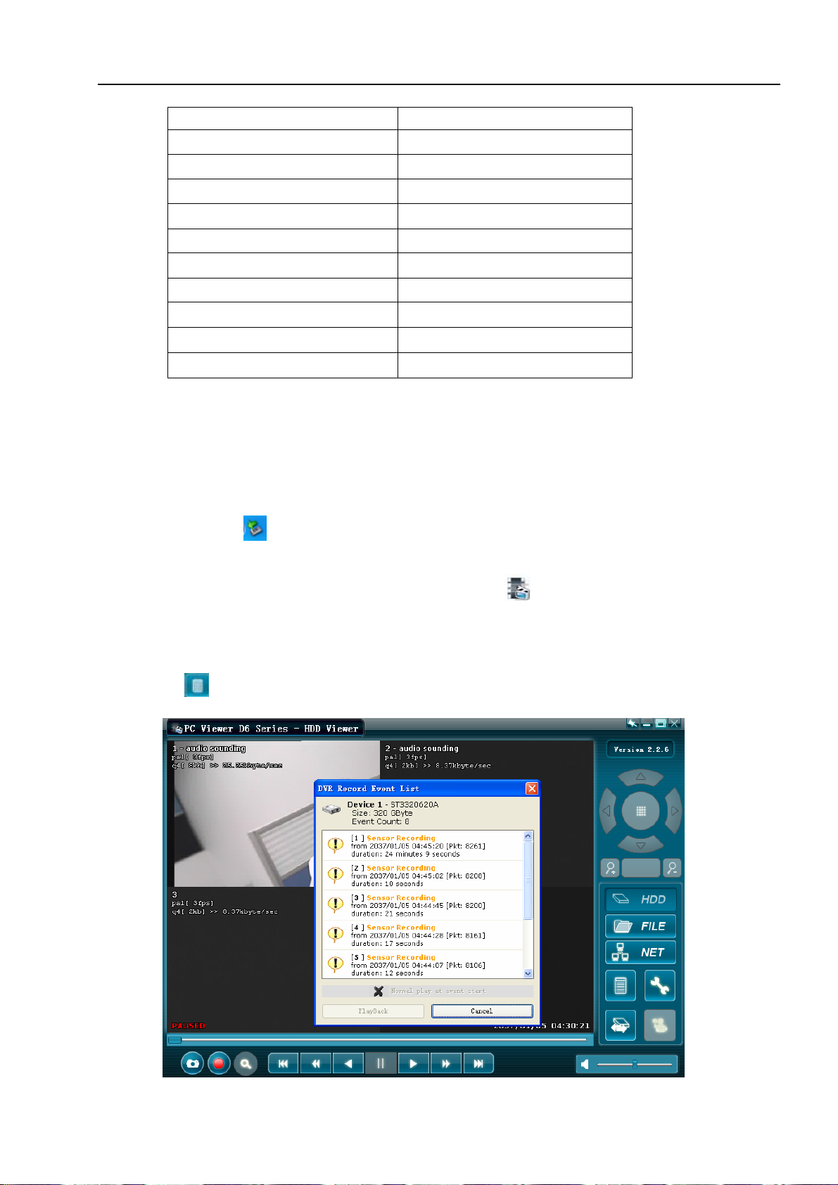
Press “
” to open the video event lists.
22
Page 24
User Manual
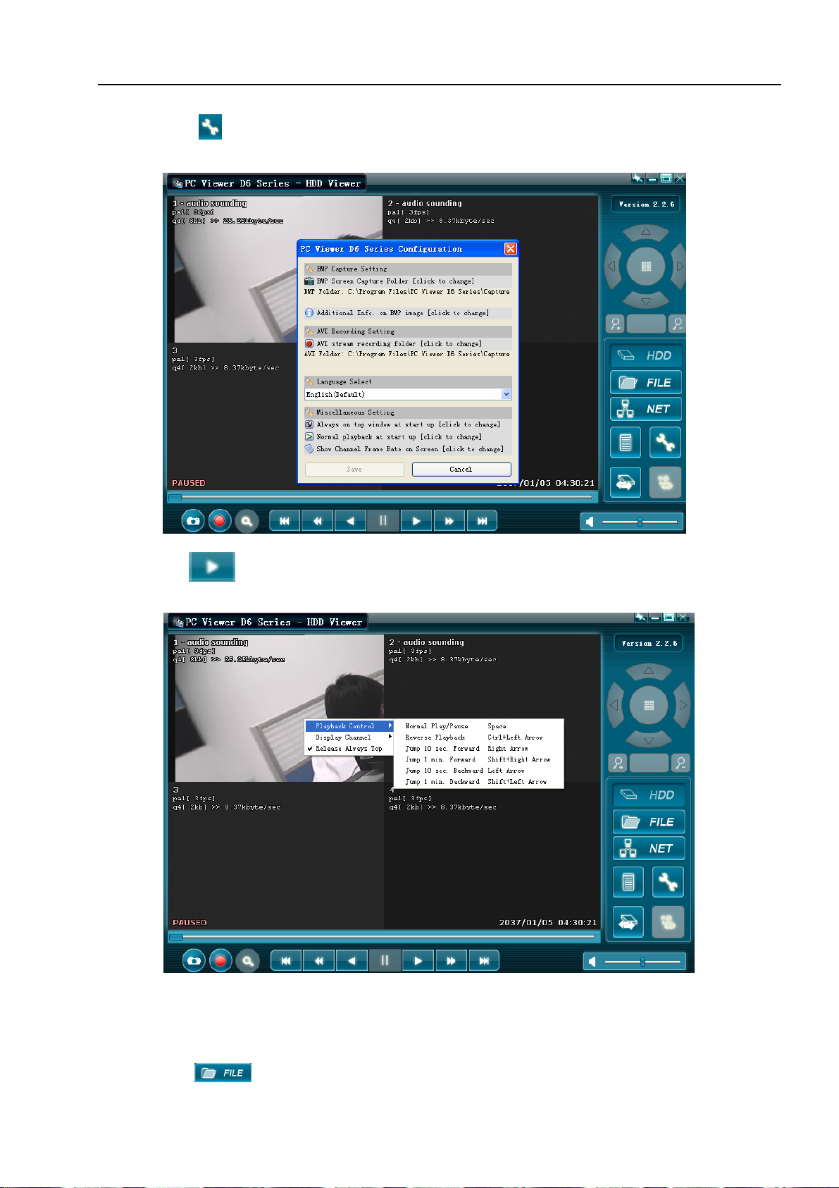
Press “ ” to configure the program local settings
Press “ ” to play video.
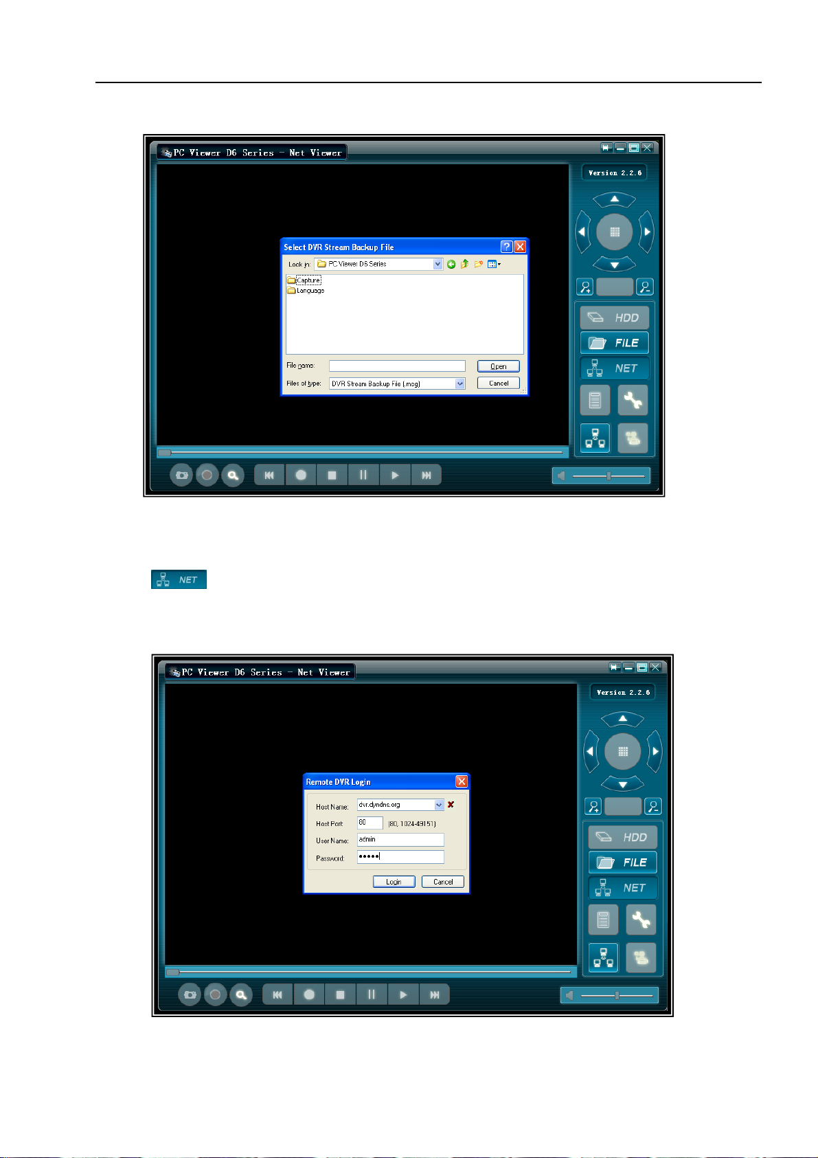
8.3.2 FILE play mode: (only when you plug a USB Memory Stick into your PC)
Press “
” to open a folder and select the file you want play.
23
Page 25
User Manual
Double click the file.
8.3.3 NET play mode:
This mode allows you to remote control your DVR via Internet or Intranet.
Press “
” to pop up the login window.
Fill in Host Name, Host Port, User Name and Password of the DVR that you want
remotely access and then press Login to enter the main page.
24
Page 26

User Manual
Chapter 9: Specification
9.1 DVR
Items Descriptions
Video Standard NTSC, PAL
Video Input/Output 4Channels BNC/2 Channels BNC
Audio Input/Output 2 Channels/2 Channels
Monitoring
Recording
Audio ADPCM2 CODEC
Video MPEG4
Motion Detection Settable Window/Level
Microprocessor 32-bit RISC Processor
Network Interface TCP/IP (RJ45)
Network Monitor IE (Internet Explorer), PC Viewer Software
PTZ Interface RS-485
USB Interface USB 2.0
Remote control IR remote control
Power supply DC 12V
9.2 CAMERAS
Image Sensor: 1/4″Color CCD
Video Output: 1.0Vp-p 75Ω(BNC)
IR LEDS: 12 PCS
IR LED Control: Photo Control(CDS)
Infrared Lamps Irradiation Distance: 12M
Resolution: 420 TV Lines
Minimum luminance: 0 Lux with 12XIR LEDs
Signal System: NTSC
Lens: 3.6mm
Electronic Shutter: 1/50(1/60) – 1/100,000 second
S/N ratio: ≥48dB(AGC OFF)
Case Material: Aluminium
Operating Temperature: -10°C - +50°C
Dimensions: 59mm x 104mm
Resolution
Features Full-D1,1-CH/4-CH Display
Resolution
Features
Quality 4-Level (Highest, High, Normal, Low)
NTSC:720X480@30fps (Each Ch)
PAL:720X576@25fps (Each Ch)
NTSC:720X240@60fps (4Ch.Total)
PAL:720X288@50fps (4Ch.Total)
Variable Frame Rate/Variable QL per
Channel
25
Page 27
User Manual
pply
(
)
Chapter 10: Appendix
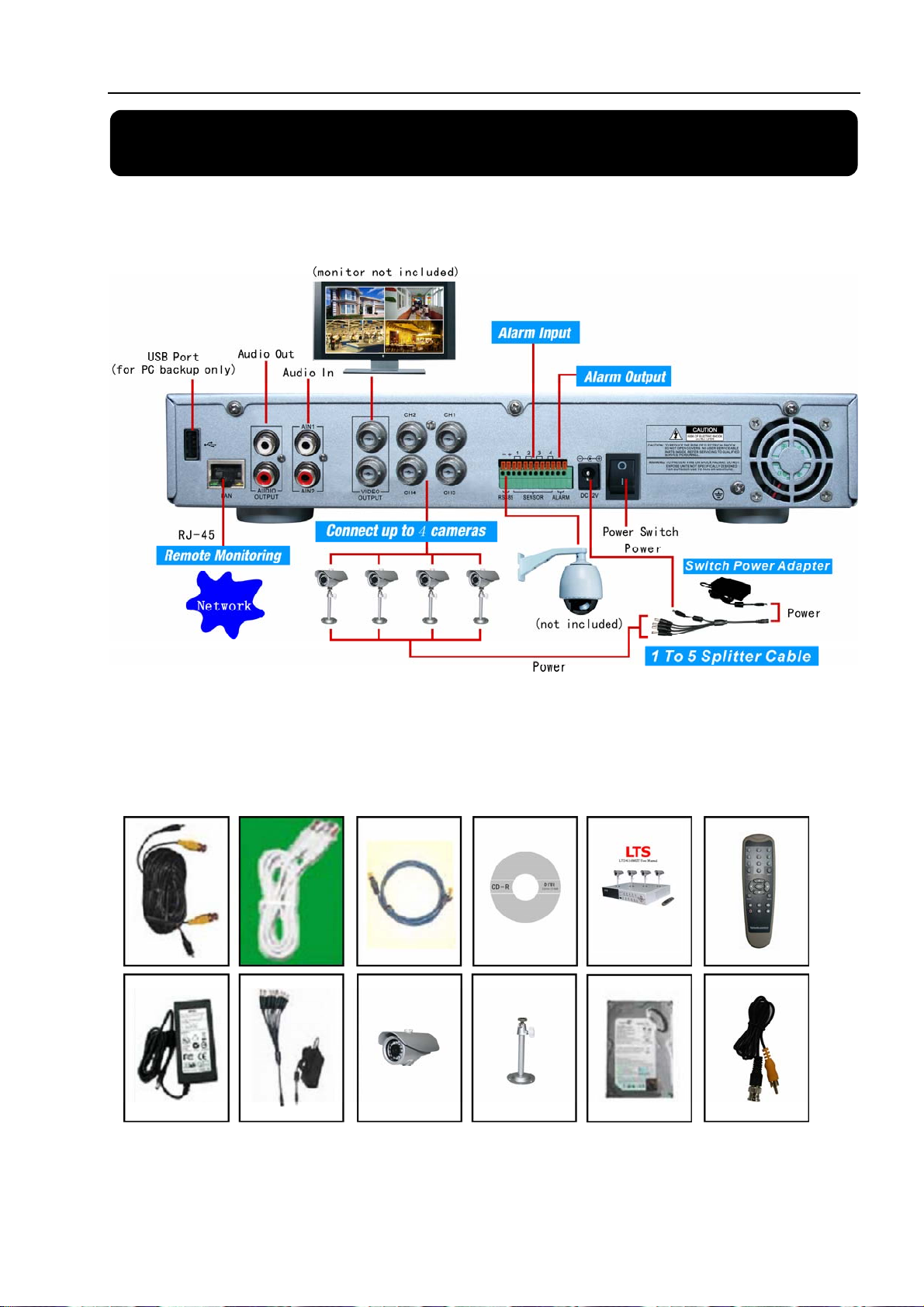
10.1 System connect sketch map
10.2 Accessories Included With DVR
Camera cables
(4 included)
USB 2.0 Cable
Ethernet Cable
Software CD Remote Control
User Manual
wer Su
Po
5 W
ay Splitter
Cameras (4
included)
Camera Stands
4 included
250GB Hard
Drive
BNC to RCA
Cable
26
 Loading...