

Page 1

DVR User Manual
For H.264 16-channel digital video recorder
All rights reserved
Page 2

Digital Video Recorder User Manual
CAUTION
Please read this user manual careful ly to ensure that you can use the device correctly and safely
We do not warrant all the content is correct. The contents of this manual are subject to change without notice
This device should be operated only from the type of power source indicated on the marking label. The voltage of the
power must be verified before using. Kindly remove the cables from th e power source if the device is not to be used for a
long period of time.
Do not install this device near any heat sources such a s radiators, heat registers, sto ves or other device that produce
heat
Do not install this device near water. Clean only with a dry cloth
Do not block any ventilation openings and ensure well ventilation around the machine
Do not power off the DVR when the device is function. The correct procedure to shut down DVR is to stop recording
firstly, and then use “shut down” button from the menu, and finally switching off the main power.
This equipment is for indoor use only. Do not expose the machine in rain or moist environment. In case any solid or
liquid get inside the machine’s case, please cut off the power supply immediately, and get it checked by a qualified
technician.
Refer all servicing to qualified service personnel. No any parts repaired by yourself without technical aid or approval.
This manual is suitable for 16-channel digital video recorders.
2
Page 3

Digital Video Recorder User Manual
Table of Contents
1 Introduction ................................................................................................................................................... 1
1.1 DVR Introduction ..................................................................................................................................................................... 1
1.2 Main Features.......................................................................................................................................................................... 1
2 Hardware Installation ..................................................................................................................................... 4
2.1 Install Hard Drive ..................................................................................................................................................................... 4
2.2 Front Panel Description ........................................................................................................................................................... 5
2.3 Rear Panel Instruction ............................................................................................................................................................. 6
2.4 Remote Controller ................................................................................................................................................................... 7
2.5 Control with Mouse .................................................................................................................................................................. 9
2.5.1 Connect Mouse ..................................................................................................................................................................................................... 9
2.5.2 Use Mouse .......................................................................................................................................................................................................... 10
3 Basic Function Instruction ............................................................................................................................. 11
3.1 Power On/Off ......................................................................................................................................................................... 11
3.1.1 Power on .............................................................................................................................................................................................................. 11
3.1.2 Power off .............................................................................................................................................................................................................. 11
3.2 Login ...................................................................................................................................................................................... 12
3.3 Live preview .......................................................................................................................................................................... 12
3.3.1 Live playback ...................................................................................................................................................................................................... 13
4 Main menu setup guide ................................................................................................................................. 14
4.1 Basic configuration ................................................................................................................................................................ 15
4.1.1 System ................................................................................................................................................................................................................ 15
4.1.2 Time & date ......................................................................................................................................................................................................... 16
4.1.3 DST ..................................................................................................................................................................................................................... 17
4.2 Live configuration .................................................................................................................................................................. 17
4.2.1 Live ..................................................................................................................................................................................................................... 17
3
Page 4

Digital Video Recorder User Manual
4.2.2 Main monitor ....................................................................................................................................................................................................... 18
4.2.3 Spot ..................................................................................................................................................................................................................... 19
4.2.4 Mask ................................................................................................................................................................................................................... 19
4.3 Record configuration ............................................................................................................................................................. 20
4.3.1 Enable ................................................................................................................................................................................................................. 20
4.3.2 Record stream .................................................................................................................................................................................................... 21
4.3.3 Time .................................................................................................................................................................................................................... 21
4.3.4 Stamp .................................................................................................................................................................................................................. 22
4.3.5 Recycle record .................................................................................................................................................................................................... 23
4.3.6 Snap ................................................................................................................................................................................................................... 23
4.4 Schedule configuration .......................................................................................................................................................... 23
4.4.1 Schedule ............................................................................................................................................................................................................. 23
4.4.2 Motion ................................................................................................................................................................................................................. 24
4.4.3 Sensor ................................................................................................................................................................................................................ 25
4.5 Alarm configuration ................................................................................................................................................................ 25
4.5.1 Sensor ................................................................................................................................................................................................................ 26
4.5.2 Motion ................................................................................................................................................................................................................. 28
4.5.3 Video loss ........................................................................................................................................................................................................... 30
4.5.4 Other alarm ......................................................................................................................................................................................................... 30
4.5.5 Alarm out ............................................................................................................................................................................................................. 31
4.6 Network configuration ............................................................................................................................................................ 31
4.6.1 Network ............................................................................................................................................................................................................... 31
4.6.2 Sub stream.......................................................................................................................................................................................................... 32
4.6.3 Email ................................................................................................................................................................................................................... 33
4.6.4 Other settings ...................................................................................................................................................................................................... 34
4.7 User management configuratio n............................................................................................................................................ 36
4
Page 5

Digital Video Recorder User Manual
4.8 P.T.Z configur ation ................................................................................................................................................................. 38
4.9 Reset ..................................................................................................................................................................................... 41
5 Record search & playback and backup ......................................................................................................... 42
5.1 Time search ........................................................................................................................................................................... 42
5.2 Event search.......................................................................................................................................................................... 43
5.3 File management ................................................................................................................................................................... 44
5.4 Image .................................................................................................................................................................................... 45
5.5 Backup .................................................................................................................................................................................. 45
6 Manage DVR ................................................................................................................................................ 46
6.1 Check system information ..................................................................................................................................................... 46
6.1.1 System information ............................................................................................................................................................................................. 46
6.1.2 Event information ................................................................................................................................................................................................ 46
6.1.3 Log information ................................................................................................................................................................................................... 46
6.1.4 Network information ............................................................................................................................................................................................ 46
6.1.5 Online information ............................................................................................................................................................................................... 46
6.2 Disk management .................................................................................................................................................................. 47
6.3 Upgrade ................................................................................................................................................................................. 47
6.4 Logoff .................................................................................................................................................................................... 47
7 Remote Surveillance ..................................................................................................................................... 48
7.1 Accessing DVR ...................................................................................................................................................................... 48
7.1.1 On LAN ............................................................................................................................................................................................................... 48
7.1.2 On WAN .............................................................................................................................................................................................................. 50
7.2 The remote live preview interface as below: .......................................................................................................................... 51
7.3 Remote playback & backup ................................................................................................................................................... 55
7.3.1 Remote playback ................................................................................................................................................................................................ 55
7.3.2 Remote backup ................................................................................................................................................................................................... 60
5
Page 6

Digital Video Recorder User Manual
7.4 Remote System configuration ............................................................................................................................................... 61
7.5 Remote Management ............................................................................................................................................................ 62
Remote Information Search ......................................................................................................................................................................................... 62
8 Mobile Surveillance ...................................................................................................................................... 63
8.1 By Phones with Windows mobile ........................................................................................................................................... 63
8.2 By Phones with Symbian ....................................................................................................................................................... 64
8.3 The Software installation for iPhone mobile clients ................................................................................................................ 66
8.4 The installation & operation methods for Android mobile clients ............................................................................................ 73
8.5 Installation and operation Methods for BlackBerry Mobile phone Client ................................................................................ 80
8.5.1 Installation instruction for BlackBerry Mobile phone Client .................................................................................................................................. 80
8.5.2 Operation method for Blackberry mobile phone client ........................................................................................................................................ 82
Appendix A F AQ….....................................................................................................................................................................86
Appendix B Calculate Recording C apacity.............................................................................................................................91
Appendix C Co mpatible Devices..............................................................................................................................................92
Appendix F 16-CH DVR Specifications....................................................................................................................................93
6
Page 7

Digital Video Recorder User Manual
1 Introduction
1.1 DVR Introduction
This model of DVR (Digital Video Rec order) is designed for high perform ance CCTV solutions. It adopts state of t he art video
processing chips and embedded Linux system. Meanwhile, it utilizes most adva nced technologies, such as standard H. 264 with
low bit rate, Dual stream, SATA interface, VGA output mouse supported, IE browser supported with full remote control, mobile
view(by phones), etc., ensuring powerful functions and hi gh stability. Due to these distinctive character istics, it is widely used in
banks, telecommunication, tra nsp ortation, factories, warehouse, and other related applications.
1.2 Main Features
COMPRESSION FORMAT
• Standard H.264 compression with low bit rate and better image quality
LIVE SURVEILLANCE
• Support HD VGA output
• Support channel security by hiding l ive display
• Display the local record state and basic information
• Support USB to make full control
RECORD MEDIA
• Support one SATA HDD to record for a longer time without any limitation
BACKUP
• Support USB 2.0 devices to backup
• Support saving recorded files with AV I standard format to a remote computer through internet
1
Page 8

Digital Video Recorder User Manual
RECORD & PLAYBACK
• Record modes: Manual, Schedule, Motion detection and Sensor alarm recording
• Support recycle after HDD full
• Resolution, frame rate and pictur e quality are adjustable
• 128MB for every video file packaging
• 2 audio channels available
• Three record search mode: time search, event search and image search.
• Support 4 screen playback simultaneously
• Support deleting and locking the recorded files one by one
• Support remote playback in Network Client throug h LAN or internet
ALARM
• 1 channel alarm output and 16 channel alarm input available
• Support schedule for motion detection and sensor alarm
• Support pre-recording and post recor di ng
• Support linked channels recordi ng once motion or alarm triggered on cer tain channel
• Support linked PTZ preset,auto cr uise and track for corresponding channels
PTZ CONTROL
• Support various PTZ protocols
• Support 128 PTZ presets and 8 auto cruise tracks
• Support remote PTZ control through internet
SECURITY
• Customize user rights: log search, system setup, two way audio, file management, disk m anagement, remote login, live view,
manual record, playback, PTZ control and remote live view
2
Page 9

Digital Video Recorder User Manual
• Support 1 administrator and, 63 users.
• Support event log recording and checking, events unlimited
NETWORK
• Support TCP/IP , DHCP, PPPoE, DDNS protocol
• Support IE browser to do remote view
• Support setup client connection amount
• Support dual stream. Network str eam is adjustable independently to fit the network bandwidth and environment.
• Support picture snap and color adjustment in remote live
• Support remote time and event search, and channel playback with picture snap
• Support remote PTZ control with preset and auto cruise
• Support remote full menu setup, changing all the DVR parameters remotely
• Support mobile surveillance by sm ar t phones , symbian, WinCE, Iphone or Gphone, Blackberry and 3G network availabl e
• Support CMS to manage multi devices over the internet
3
Page 10
Digital Video Recorder User Manual
2 Hardware Installation
Notice: Check the unit and the accessories after getting the DVR.
Please disconnect the power before being connected to other devices. Don't hot plug in/out.
2.1 Install Hard Drive
Notice: 1. This series support one SATA hard drive. Please use the hard drive the manufacturers reco mmend specially for
security and safe field. Please refer to “Appendix C Compatible Devices 3”.
2. Please calculate HDD capacity according to the r ecording sett ing. Please ref er to “Appendix B Calculate Recor ding
Capacity”.
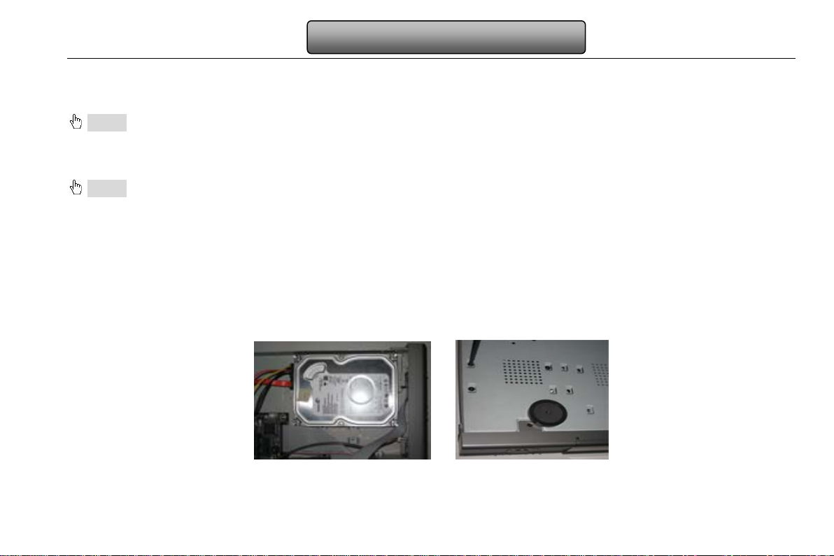
Step1: Unscrew and Open the top cover.
Step2: Connect the power and data cables. Place the HDD onto the bottom case as Fig 2.1:
Step3: Mount the HDD as Fig2.2:
Note: For installation con venience, please connect the power and data cables firs t, and then wind the screws to fix the HDD.
Fig 2.1 Connect HDD Fig 2.2 Screw HDD
4
Page 11
Digital Video Recorder User Manual
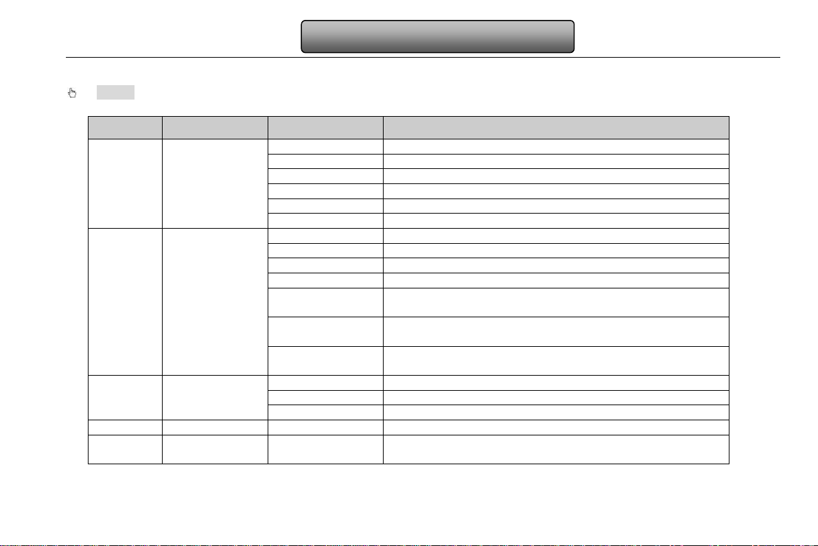
Power
Power indicator, when connection , the lights up blue
HDD
When HDD is writing and reading , the lights up blue
Net
When access to network , the lights up blue
Backup
When backup files and data, the lights up blue
Play
When playing video, the lights up blue
REC
When recording, the lights up blue
RECORD
Record manually
PLAY
Enter play interface
REW
Rewind key
FF
Fast forward
1. Enter menu in live
2. Increase the value in setup
1. Decrease the value in setup
2. Enter backup mode in live
1. Quit play mode
2. Exit the current interface or status
Direction button
Change direction to select items
Multi-screen
Change screen display mode like1/4/9/16 channel
Enter button
Confirm selection
5
IR receiver
IR
For remote controller
USB
To connect external USB devices like USB fl ash, USB HDD
for backup or update firmware; or connect to USB mouse
2.2 Front Panel Description
Notice: The front panel descriptions are only for reference; please make the object as the standard.
Item
1
2
Type
Work state
indicator
Compound
button
Name Description
MENU/+
BACKUP/-
STOP/ESC
4
6
Input button
USB port
5
Page 12
Digital Video Recorder User Manual
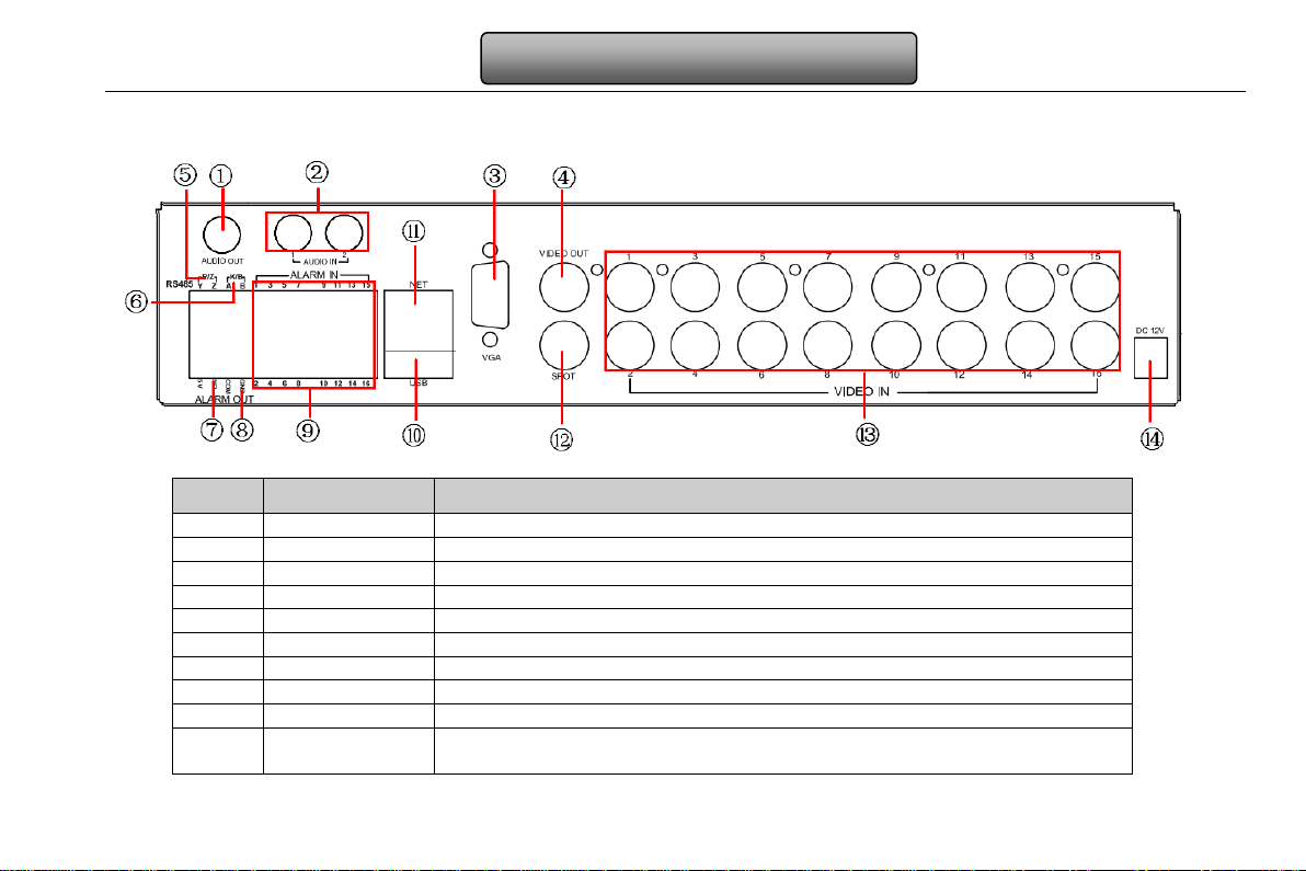
1
Audio out
Audio output, connect to the sound box
2
Audio in
2 CH Audio input
3
VGA port
VGA output, connect to monitor
4
Video out
Connect to monitor
5
P/Z
Connect to speed dome
6
K/B
Connect to keyboard
7
Alarm out
1-ch relay output. Connect to externa l al ar m
8
+ 5V and GND
+5 V and Grounding
9
ALARM IN
Connect to external sensor1-16
To connect external USB devices lik e USB flash, USB HDD for backup or
update firmware; or connect to USB mouse
2.3 Rear Panel Instruction
The rear Panel interface for 16-ch is sho wn as Fig 2.3:
Fig 2.3 Rear Panel for 16-ch
Item Name Description
10 USB port
6
Page 13

Digital Video Recorder User Manual
11
NET
Network port
no menu show
13
Video in
Video input channels from 1-16
14
Power input
DC12V
Item Name Description
12 Spot out
Connect to monitor as an AUX output channel by channel. Only video display,
2.4 Remote Controller
It uses two AAA size batteries and works after loading batteries as following:
Step1: Open the battery cover of the Remote Controller.
Step2: Place batteries. Please take care the polarity (+ and -).
Step3: Replace the battery cover.
Notice: Frequently defect checking as following.
1. Check batteries poles.
2. Check the remaining charge in the batteries.
3. Check IR controller sensor is mask.
If it still doesn't work, Please change a new remote controller to try, or contact your dealers.
The interface of remote controller is shown in Fig2.4 Remote Controller.
7
Page 14

Digital Video Recorder User Manual
1
Power Button
Soft switch off to stop firmware running. Do it before power off.
Get information about the DVR like firmware version, HDD
information
3
REC Button
To record manually
5
Multi Screen Button
To choose multi screen display mode
6
SEARCH Button
To enter search mode
7
MENU Button
To enter menu
8
ENTER Button
To confirm the choice or setup
9
Direction Button
Move cursor in setup or pan/title PT Z
10
+/- Button
To increase or decrease the value in setup
11
Playback Control Button
To control playback, Fast forward/ rewind/stop/single frame play
12
AUDIO Button
To enable audio output in live mode
Item Name Function
2 INFOR Button
4 Digital Button Input digital or choose camera
Fig 2.4 Remote Controller
8
Page 15

Digital Video Recorder User Manual
13
Auto Dwell Button
To enter auto dwell mode
14
BACKUP Button
To enter backup mode
Move camera/ZOOM/FOCUS/IRIS/SPEED control
Item Name Function
15 PTZ Control Button
Operation processes with remote controller to control multi-DVR
The device ID of the DVR is 0. It’s not necessa ry to reset the device ID when a remote is to be used to cont rol a single DVR.
However when controlling multiple DV R with multiple remote controll ers, the user would need to configur e the device ID, please
refer to below steps:
Step1: Activate rem ote controller to control DVR: Turn the IR sensor of the remote controller to the I R receiver that on the front
panel, press the number key 8 twice, then input device ID of the DVR to be controlled(Range from: 0-65535; the default device ID is
0.) After that, press ENTER button to confirm.
Step2: User can check the device ID by enter into System configurat ionBasic configurationdevice ID. User also can set other
DVR with the same device ID. For more convenient to operate, we don’t recomm end user to set the device ID too long.
Step3: Cancel controller to control DVR: turn the IR senso r of the rem ote co ntr oll er to t he I R receive r t hat on t he front panel, pres s
the number key 8 twice, then input the device ID that needs to be cancelled from controlling, press ENTER button to confirm. After
that, the DVR will not be controlled by remote contr oller.
To control PTZ camera:
2.5 Control with Mouse
2.5.1 Connect Mouse
It supports USB mouse through the ports on the rear panel.
Notice: If mouse is not detected or doesn't work, ch eck below steps:
1. Make sure the mouse plugs in the USB mouse port not the USB port.
2. Change a mouse to try.
9
Page 16

Digital Video Recorder User Manual
2.5.2 Use Mouse
In live:
Double-click left button on one camera to be full screen display. Double-click again to return to the previous screen display.
Click right button to show the control bar at the bottom of the screen. Here are all control and setup. Click right mouse again to hide
the control bar.
In setup:
Click left button to enter. Click right button to cancel setup, or retur n to the previous.
If want to input the value, move cursor to t he bla nk and cl ick. An input window will appear as F ig2. 5. I t su pports digitals, l ett ers and
symbols input.
Fig 2.5 Digital Numbers and Letters Input Window
Users can change some value by the wheel, such as time. Move cursor onto the value, and roll the wheel when the value blinks.
It supports mouse drag. I.e. Set motion det ect ion ar ea: click customized, hold l eft button and dr ag to se t mot ion det ect ion ar ea. Set
schedule: hold left button and drag to set schedule time.
In playback:
Click left button to choose the options. Click right button to return to live mode.
In backup:
Click left button to choose the options. Click right button to return to previous pi cture.
In PTZ control:
Click left button to choose the buttons to control the PTZ. Click right button to ret urn to live.
Notice: Mouse is the default tool in all the operation below unless Exceptional indication.
10
Page 17

Digital Video Recorder User Manual
3 Basic Function Instruction
3.1 Power On/Off
Before you power on the unit, please make sur e all the connection is good.
3.1.1 Power on
Step1: connect with the source power; switch on the power button near the power port on the rear panel.
Step2: the device will be loaded, and the power indicator will display blue.
Step3 before start, a WIZZARD window will be pop-up and show some information about time zone,time setup ,network
configuration, record configur ation and disk management. U ser can setup here and refer to t he concrete setup steps from the
corresponding chapters. If users don’t want to setup Wizard, please click Exit button to exit.
After the device power on, if there is no menu or only has live image display, user can long press ESC button to switch.
Notice: this serial device can only display options on either VGA monitor or BNC monitor at one time, if there is live image display
without menu options, please check if there is display on other device/monitor, or long press ESC key to wait for login dialog box
to appear. Long press ESC key can switch the output between BNC and VGA.
3.1.2 Power off
User can power off the device by using remote controller、keyboard and mouse.
By remote controller:
Step1: press Power button, the Shut down window will appear, click OK, the unit will power off after a while.
Step2: disconnect the power.
By keyboard and mouse:
Step1: enter into
Step2: click OK, the unit will power off after a while.
Step3: disconnect the power.
Menu, and then select “System Shut Do wn” icon, the Shut down window will appear.
11
Page 18

Digital Video Recorder User Manual
Symbol
Meaning
Green
Manual record
Yellow
Motion detection record
Red
Sensor Alarm record
Blue
Schedule record
3.2 Login
User can login and logout the DVR system. User cannot do any other operations except changing the multi-screen display once logout.
Notice: the default user name and password is “admin” and 123456.
The concr ete operation steps for change password, add or delete user please refer to User management configurat ion for
more details.
3.3 Live preview
Fig 3-1 Login
Fig 3-2 live preview interface
12
Page 19

Digital Video Recorder User Manual
3.3.1 Live playback
Click Play button to playback the record. Refer to Figure3-3. User can do concrete operation by click the buttons on screen.
Fig 3-3 live playback
13
Page 20

Digital Video Recorder User Manual
4 Main menu setup guide
Click right mouse or press ESC button on the front panel, the control bar will display on the bottom of the screen, refer to Fig 4-1:
Fig 4-1 main menu toolbar
Click the icon beside the screen display mode, a channel select dialog will appear.
Dwell: Range of selecting to dwell is from singl e picture preview mode to 1/4/6/9/16 picture preview mode.
Color: Click this button; user can adjust the color of live pictures.
E-Zoom: Single channel large screen electronic am pli fication.
Left click the channel which needs to amplify; Click the right mouse, se lect Zoom in button and then click the left mouse to ampli fy
the image. Press left mouse to drug the cursor, user can view the image. Double-click the left mouse to exit. Click the right mouse to
return to the main interface.
Volume: Enable sound.
PTZ: Click the PTZ butto n, user can control rotation position, speed of the dome and start track, auto scan or cruise in this interface.
User can refer to PTZ configuration for m or e details.
Snap: click this button; user can snap the live pictures. These pictures will automatically be saved in t he SATA disk.
Record: Click this button, use r can start manual record.
Playback: Click this button, the devi ce can playback the record files.
User can click
Click Menu
as Fig 4-2; press MENU button on the front panel or operate with remote controller also can display the main m enu. Click Setup
button and drag the tool bar anywhere on screen display with the left mouse.
button, the Login window will po pup. Input the user name and password to lo gon the s ystem interface as shown
14
Page 21

icon will pop-up the configuration menu:
Digital Video Recorder User Manual
Fig 4-2 system setup
4.1 Basic configuration
Basic configuration includes thr ee sub menus: system、date& time and DST.
4.1.1 System
Step1: enter into system configurationbasic configurationsystem; refer to Fig 4-3: Step2: in this interface user can setup the device name, device ID, video format, max network users, VGA resolution and language. The definitions for every parameters display as below: Device name: the name of the device. It may display on the client end or CMS that help user to recognize the device remotely. Video format: two modes: PAL and NTSC. User can select the video format according to that of camera.
Fig 4-3 basic configuration-basic
Password check: enable this option, us er needs to input user nam e and password can do corresponding operat ions with the
15
Page 22

Digital Video Recorder User Manual
relevant right in system configur ation.
Show time: display time in live.
Show wizard: tick off this item, there will display an opening wizard with time zone and time set up information.
Max network uses: set the max user amount of network connection.
VGA resolution: the resolution of live display interface, range from: VGA800*600、VGA1024*768、VGA1280*1024and CVBS
Note:When switch between VGA and CVBS will change the menu output mode, please connect to relevant monitor.
Language: setup the menu language.
Note: After changed the language and video output, the device needs to login again.
4.1.2 Time & date
Step1: enter into system configurationbasic
configurationtime & date; refer to Fig 4-4:
Step2: set the date format, time format, time zone in this interface; tick off “sync time with NTP server” to refresh NTP server date; user also can adjust system date manually.
Fig 4-4 basic configuration-time & dat e
16
Page 23

4.1.3 DST
Digital Video Recorder User Manual
Step1: enter into system configurationbasic
configurationDST; refer to Fig 4-5:
Step2: in this interface, enable daylight saving time, time
offset, mode, start & end month/week/date, etc.
Fig 4-5 basic configuration-DST
4.2 Live configuration
Live configuration includes four submenus: live, main monitor, Spot and mask.
4.2.1 Live
In this interface, user can setup camera name, adjust colors: brightness, hue, saturation and contrast.
Step1: enter into system configurationlive configurationlive; refer to Fig 4-6:
Note: Click Camera Name, a soft keyboard w ill pop up. User can self-define th e camer a name . Cli ck Shift button, user can input Capital letters; click Shift button again, user can input Chinese characters.
Step2: tick off camera name; click “setting” button, a window will pop-up as Fig 4-7:
Fig 4-6 live configurationlive
17
Page 24

Digital Video Recorder User Manual
Step3: in this interface, user can adjust brightness, hu e,
saturation and contrast in live; click “default” button to
resort default setting, click “OK” button to save the
setting.
Step4: user can setup all channels with same parameters,
tick off “all”, then do relevant setup.
Fig 4-7 live-color adjustment
4.2.2 Main monitor
Step1: enter into system configurationlive configurat ionmain monitor; refer to Fig 4-8:
Step2: select split mode: 1×1、2×2、2×3、3×3、4×4 and channel.
Step3: dwell time: the time interval for a certain dwell
picture display switching to next dwell picture display
Step4: selected the split mode, then setup current picture
group. Click
groups of dwell picture, click
channel groups of dwell picture.
button to setup the previous channel
button to set the latter
Fig 4-8 live configuration-host monitor
18
Page 25

Digital Video Recorder User Manual
4.2.3 Spot
Step1: enter into system configurationlive configurat ionSpot; refer to Fig 4-9:
Step2: select split mode: 1×1and channel.
Step3: dwell time: the time interval for a certain dwell
picture display switching to next dwell picture display.
Step4: selected the split mode, then setup current picture
group. Click
groups of dwell picture, click
channel groups of dwell picture.
Fig 4-9 live configuration-Spot
4.2.4 Mask
User can setup private mask area on the live image picture, max threes areas.
Setup mask area: click Setting button, enter into live
image to press left mouse and drag mouse to set mask
area, refer to below picture. Click Apply button to save
the setting.
Delete mask area: select a certain mask a rea, click left
mouse to delete that mask area, click Apply button to
save the setting.
Fig 4-10 live configuration-mask
button to setup the previous channel
button to set the latter
19
Page 26

Digital Video Recorder User Manual
Parameter
Meaning
ecord switch of every
channels
Audio
Enable live record audio
4.3 Record configuration
Record configuration includes six sub menus: enable, record bit rate, time, recycle record, stamp and snap.
4.3.1 Enable
Step1: enter into system configurationrecord configurationenable; refer to Fig 4-11:
Fig 4-11 record configuration-enable
Setup mask area live image mask area
Step2: tick off record, audio and record time.
Step3: user can setup all channels with same parameters,
tick off “all”, then to do relevant setup.
Record R
20
Page 27

4.3.2 Record stream
Parameter
Meaning
Resolution
Support CIF
low, medium, higher and highest.
Digital Video Recorder User Manual
Step1: enter into system configurationrecord
configurationrecord bit rate; refer to Fig 4-12:
Step2: setup fps, resolution and quality
Step3: user can setup all channels with same parameters.
Tick off “All” to do relevant setup.
Note: if the rate value set is over high the maximum resources of the device, the value will be adjusted automatically.
Fig 4-12 record configuration-record bit rate
Definitions and descriptions of Record stream:
Rate
Quality The higher the value is, the clearer the recorded image is. Six options: lowest, lower,
4.3.3 Time
Step1: enter into system configurationrecord configuration time; refer to Fig 4-13:
Pre-alarm record time: the record time before event happen i.e. record time before motion detection or sensor alarm is
triggered.
Post-alarm record: set the post recording time after the alarm is finished, five options: 10s、15s、20s、30s and 60s.
Expire time: the hold time of saved reco rds. If the set date is overdue, the record files will be deleted automatica l ly.
Step2: user can setup all channels with same parameters, tick off “all”, t hen to do relevant setup.
Range from: 1-30(NTSC)1-25(PAL)
21
Page 28

Digital Video Recorder User Manual
Fig 4-13 record configuration-time
4.3.4 Stamp
Stamp:User can overlap the channel name and time stamp on video.
Step1: enter into system configuration record
configuration stamp; refer to Fig 4-14:
Step2: tick off camera name, time stamp; click Set
button, user can use cursor to drag the c amera name
and time stamp in random positions, refer to below
Figures:
Step3: user can setup all channels with same
parameters, tick off “all”, then to do relevant setup.
Fig 4-14 record configuration-stamp
22
Page 29

Digital Video Recorder User Manual
Before drag after drag
4.3.5 Recycle record
Step1: enter into system configurationrecord configurationrecycle record;
Step2: tick off recycle record, the recycle record function will enable, it will cover the earli er recorded files and keep recodin g
when HDD is full; if disenable this function, it will stop recording when HDD is full.
Step3: click “default” button to resort def ault setting; click “apply” butt on to save the setting; click “exit” button to exit current
interface.
4.3.6 Snap
In this interface, user can set up Resolut ion, quality, snap interval, snap number.
4.4 Schedule configuration
Schedule configuration includ es three sub menus: schedule, motion and alarm.
4.4.1 Schedule
The volume means the seven days of a week from Monda y to Sunday, the row means 24 hours of a day. Click the grid to do relevant setup. Blue means checked area, gray means unchecked area. Step1: enter into system configurationschedule conf igurationschedule; refer to F i g 4-15:
23
Page 30

Digital Video Recorder User Manual
Fig 4-15 schedule configuration-schedule
Step2: select channel, double-click and a dialog box will po p-up as Fig 4-16, user can edit week schedule:
Fig 4-16 schedule-week schedule
① Click “add” button to add a certain day schedule; click “delete” button to delete the selected schedule.
Copy: user can copy the specify schedule to other dates.
Click “OK” button to save the setting, click “Exit” button to exit current interface.
② User can apply the schedule setting of certain channel to ot her or all channels, just only select channel and click “Copy”
button.
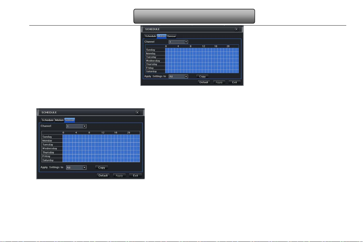
4.4.2 Motion
Step1: enter into system configurationschedule conf igurationmotion; refer to Fig 4-17:
Step2: the setup steps of motion are familiar with schedule; user can refer to 4.4.1 Schedule for details.
24
Page 31
Digital Video Recorder User Manual
Fig 4-17 schedule configuration-motion
Note: the default schedule of motion detection is full-selected, that is, the color of schedule setting i nterface is blue.
4.4.3 Sensor
Step1: enter into system configurationschedule
configurationalarm; refer to F ig 4-18:
Step2: the setup steps of alarm are familiar with schedule;
user can refer to 4.4.1 Schedule for details.
Note: the default schedule of sensor is full-selected, that is, the color of schedule setting inter f ace is blue.
Fig 4-18 schedule configuration-sensor
4.5 Alarm configuration
Alarm configuration includes five sub menus: sensor, motion, video loss, other alarm and alarm out.
25
Page 32

Digital Video Recorder User Manual
4.5.1 Sensor
Sensor includes three sub menus: basic, alarm handling and schedule.
① Basic
Step1: enter into system configurationalarm configurationsensorbasic; refer to Fig 4-19: Step2: enable sensor alarm, set the alarm type according to triggered alarm type. Two option: NO and NC. Step3: user can setup all channels with same parameters, tick off “all”, then to do relevant setup.
Fig 4-19 alarm configuration-sensor-basic
② Alarm handling
Step1: enter into system configurationalarm configurationsensoralarm handling; refer to Fig 4-20:
Step2: select hold time, click Trigger button, and a dialog box will pop-up as Fig 4-21:
Fig 4-20 alarm configuration-sensor-alarm handling Fig 4-21 alarm handling-trigger
26
Page 33

Digital Video Recorder User Manual
Step3: Buzzer: If selected, the local buzzer would be activated on an alar m.
Full screen alarm: when triggered alarm, th er e will pop up full screen alarm.
Email: If selected. When an alarm trigged, a notification email will be sent to user’s designed email box including trigger events,
time, snap pictures, device name, ID camera name etc.
Snap: Select channels. When an alarm is t rigged, the system will automatically save the captur ed pictures from the selected
channel. If user tick off Email function, these pictures will also be sent to user’s designed email box.
To alarm out: tick off the channel, there will be triggered alarm out in the designated channel. Click OK button to save the setting;
click Exit button to exit the curr ent interface.
To record: tick off recoding channels. It will record the camera when alarm triggered. Click OK button to save the setting; click
Exit button to exit the current int er face.
To P.T.Z: set linked preset and cruise for alarm. User can select any channel and multi channels as linked chan nels. Click OK
button to save the setting; click Exit button to exit the current interface.
Step4: user can setup all channels with same parameters, tick off “all”, t hen to do relevant setup.
③ Schedule
Step1: enter into system configurationalarm configurationsensorschedule; refer to Fig 4-22:
Fig 4-22 sensor-schedule
Step2: the setup steps of sensor schedule are familiar with schedule; user can refer to 4.4.1 Schedule for details.
Note: the default schedule of sensor is full-selected, that is, the color of schedule setting interface is blue.
27
Page 34

Digital Video Recorder User Manual
4.5.2 Motion
Motion includes two sub menus: motion and schedule.
① Motion
Step1: enter into system configurationalarm configurationmotion; refer to Fig 4-23:
Fig 4-23 alarm configuration-motion
Step2: enable motion alarm, set alarm hold time which me ans time int erv al bet ween t wo adjacent detective motions. If there is
other motion detected during the interval period which is considered continuous movement; otherwise, it will be considered that
those two adjacent detective motions are two different motion events. Click Trigger button, a dialog box will pop-up:
Step3: the setup steps of motion trigger are familiar with alarm handling; user can refer to Chapter 4.5.1 Sensor alarm
handling for more details.
Step4: click Area button, a dialog box will pop-up as Fig 4-24:
Fig 4-24 motion-area
Step5: in the Area interface, user can drag slide bar to set the sensitivity value (1-8), the default value is 4. The higher the value
is the high er sensitivity you get. Due to the sensitivit y is influenced by color and time (da y or night), user can adjust its value
according to the practical conditions; click
icon, set the whole area as detection area; click icon, the set detection area
28
Page 35

Digital Video Recorder User Manual
will be cleared; click icon, user can t est whether the sensitivity valu e and motion area are suitable according ly(refer to
following picture); Click
Note: when user drag mouse to set motion detection area, they have to click icon to clear all set d etection area
firstly, and then make the operation.
Step6: user can setup all channels with same parameters, tick off “all”, t hen to do relevant setup.
② Schedule
Step1: enter into system configurationalarm configurationschedule; refer to Fig 4-25:
icon, to save the setting; click icon, exit current interface.
Fig3-25 alarm configuration-schedule
Step2: the setup steps of alarm schedule are familiar with schedule; user can refer to 4.4.1 Schedule for details.
29
Page 36

Digital Video Recorder User Manual
4.5.3 Video loss
Step1: enter into system configurationalarm configur ationvideo loss; refer to Fig 4-26:
Step2: the setup steps of video loss trigger are familiar with
alarm handling; user can refer to Chapter 4.5.1 Sensor alarm
handling for more details.
Step3: user can setup all channels with same parameters, tick
off “all”, then to do relev ant setup.
Fig 4-26 alarm configuration-video loss
4.5.4 Other alarm
This tab gives a choice to configure alarm for Disk Full or IP Conflict or the Disconnect event
Step1: enter into system configurationother alarm; refer to Fig
4-27:
Step 2: Use the dropdown menu and select the event for the
alarm.
Step 3: Check the required trigger options
If the selected event is ‘Disk Full’, then use the drop do wn box
for ‘Disk Shortage Alarm’ to choose a threshold value for
remaining HDD space. If the threshold value is reached, the
Fig4-27 other alarm
system will trigger the Disk Full Alarm.
30
Page 37

Digital Video Recorder User Manual
Buzzer – If selected the local buzzer would be activated on an alarm.
Email: If selected, the DVR will send an email alert to the preconfigured email address.
To A larm Out: If selected would trigger the inbuilt relay on the set event alarm.
4.5.5 Alarm out
Alarm out includes three sub menus: alarm out, schedule and buzzer
① Alarm out
Step1: enter into system configurationalarm out; refer
to Fig 4-28:
Step2: in this interface, set relay alarm out name, select
hold time which means the interval tim e between the
two adjacent alarms.
Step3: user can setup all channels with same
parameters. Tick off “all” to do relevant setup.
Fig 4-28 system configuration-alarm out
② Schedule
Step1: enter into system configurationschedule;
Step2: the setup steps of alarm out schedule are familiar with schedule; user can refer to 4.4.1 Schedule for details.
Note: the default schedule of motion detection is full-selected, that is, the color of schedule setting interface is blue.
③ Buzzer
Step1: enter into system configurationbuzzer;
Step2: tick off Buzzer, set buzzer alarm hold time
4.6 Network configuration
Network configuration include s four submenus: network, sub stream, Email and other settings.
4.6.1 Network
Step1: enter into system configurationnetwork configurationnetwork; refer to Fig4-29:
31
Page 38

Digital Video Recorder User Manual
Step2: HTTP port: the default value is 80. If the value changed, user needs to add the port number when typing IP address in IE
address blank .i.e. set HTTP port to 82, IP address:
http://192.168.0.25, user needs to input that address:
http://192.168.0.25:82 into I E browser.
Server port: communication port.
Step3: Tick off the " Obtain an IP address automatically",
the device will distribute IP address, subnet mask, and
gateway IP and DNS server.
Step4: enable PPPoE, user can directly connect the DVR
to internet via ADSL, then input the user name and
password; click TEST button to test the effectiveness of
the relevant information.
Fig 4-29 network configuration-network
4.6.2 Sub stream
Step1: enter into system configurationnetwork
configurationsub stream; refer to Fig 4-30:
Step2: select fps, resolution and quality.
Step3: user can setup all channels with same
parameters. Please tick off “all” to do relevant setup.
Fig 4-30 network configuration-sub st r eam
32
 Loading...