

Page 1

NetViewer & CMS Support in IE
(Model: 16CH MPEG-4 DVR)
1. NetViewer in IE (http://www.goddns.org/xp)
2. CMS in IE (http://www.goddns.org/xp )
* IE stands for Internet Explorer.
Page 2
1. NetViewer in IE: remote viewing in IE
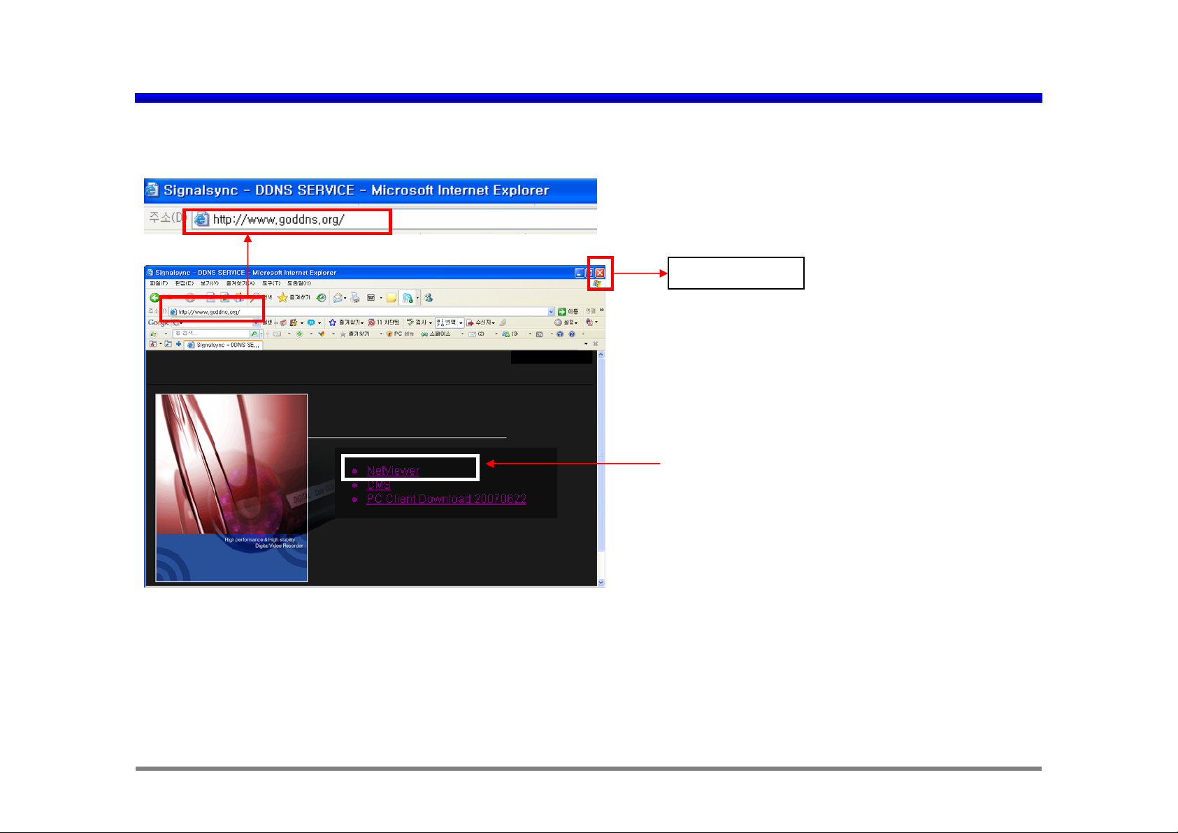
1. Please write http://www.goddns.org/xp in Internet explorer for remote viewer.
xp
Exit NetViewer
Please click “NetViewer” for remote viewing
through IE.
Jun. 22, 2007
Page 3
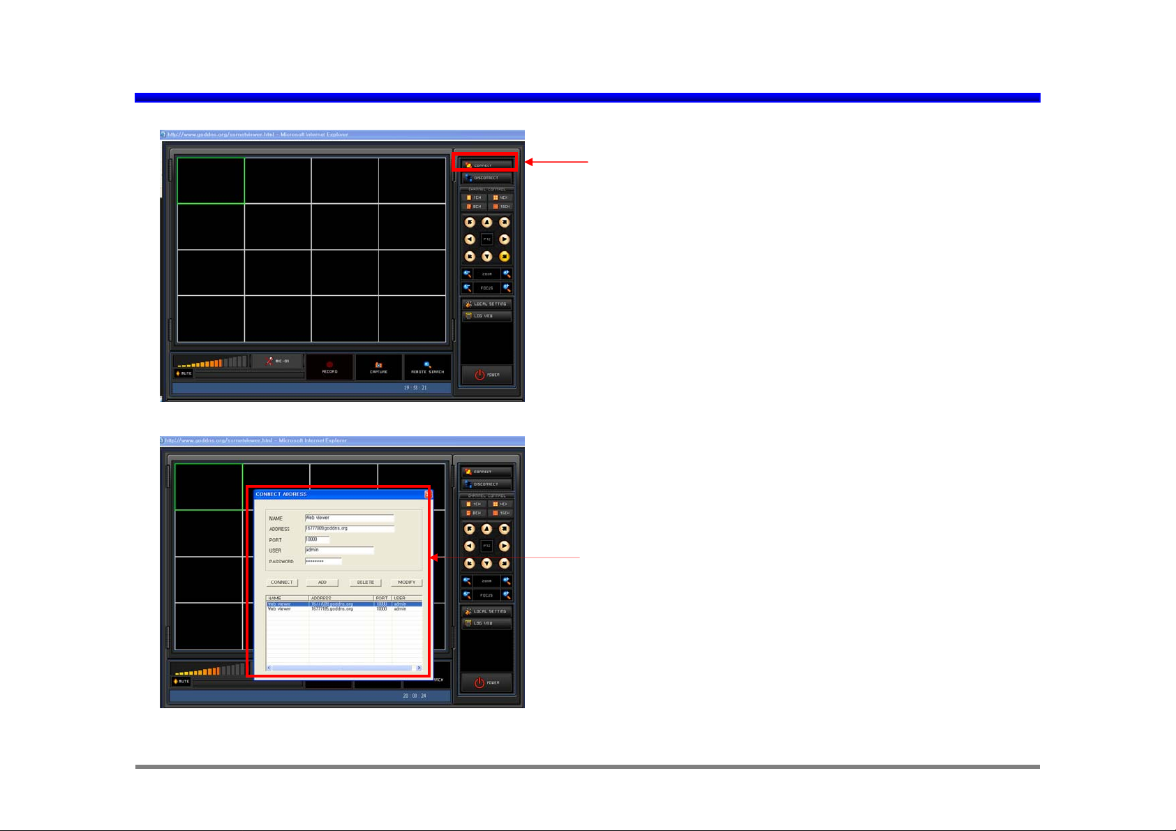
Remote viewing Start of NetViewer in IE
Please click “CONNECT” for remote viewing via IE.
“CONNECT ADDRESS registration.
Jun. 22, 2007
Page 4
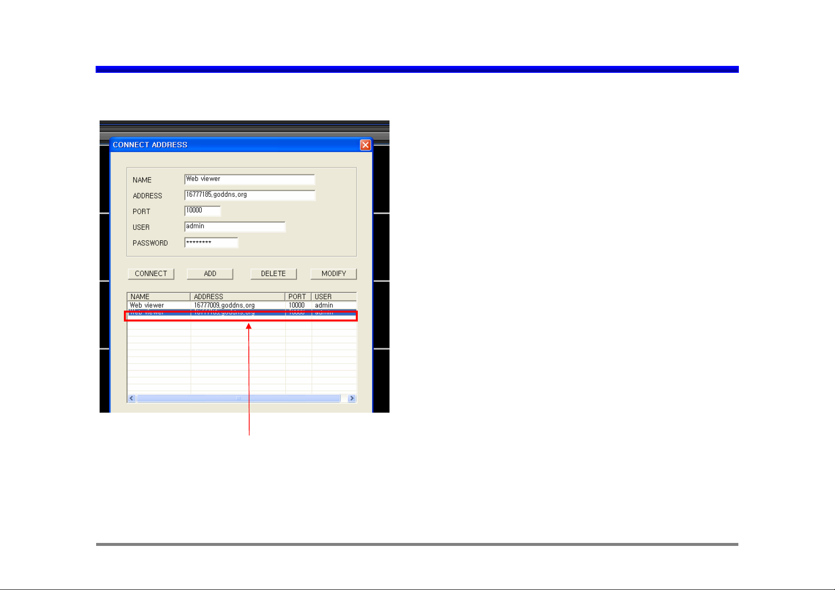
CONNECT ADDRESS Registration of NetViewer in IE
< An Example of CONNECT ADDRESS Registration >
1) NAME: Any name can be input. Ex, Web viewer.
2) ADDRESS: 16777009.goddns.org (demo DVR IP address)
Your DVR IP address can be used.
3) PORT: 10000
(Port should be opened from 10000 to 10020.)
Now this port number is fixed as 10000.
But it can be adjustable with other por t n u mb er soon.
4) USER: admin
5) PASSWORD: 11111111 (eight one)
If all information is registered properly, “ADD” should be clicked
to save the registration information.
If the registration of other DVR which has different IP address is
needed, different NAME, ADDRESS and so on can be
registered with same way.
“Registered CONNECT ADDRESS”
In order to select viewing site, first click the one of “registered
CONNECT ADDRESS” with mouse.
And then please click “CONNECT”.
Registered viewing site can be deleted as clicking “DELETE”, or
can be modified as clicking “MODIFY” after modifying it.
Jun. 22, 2007
Page 5
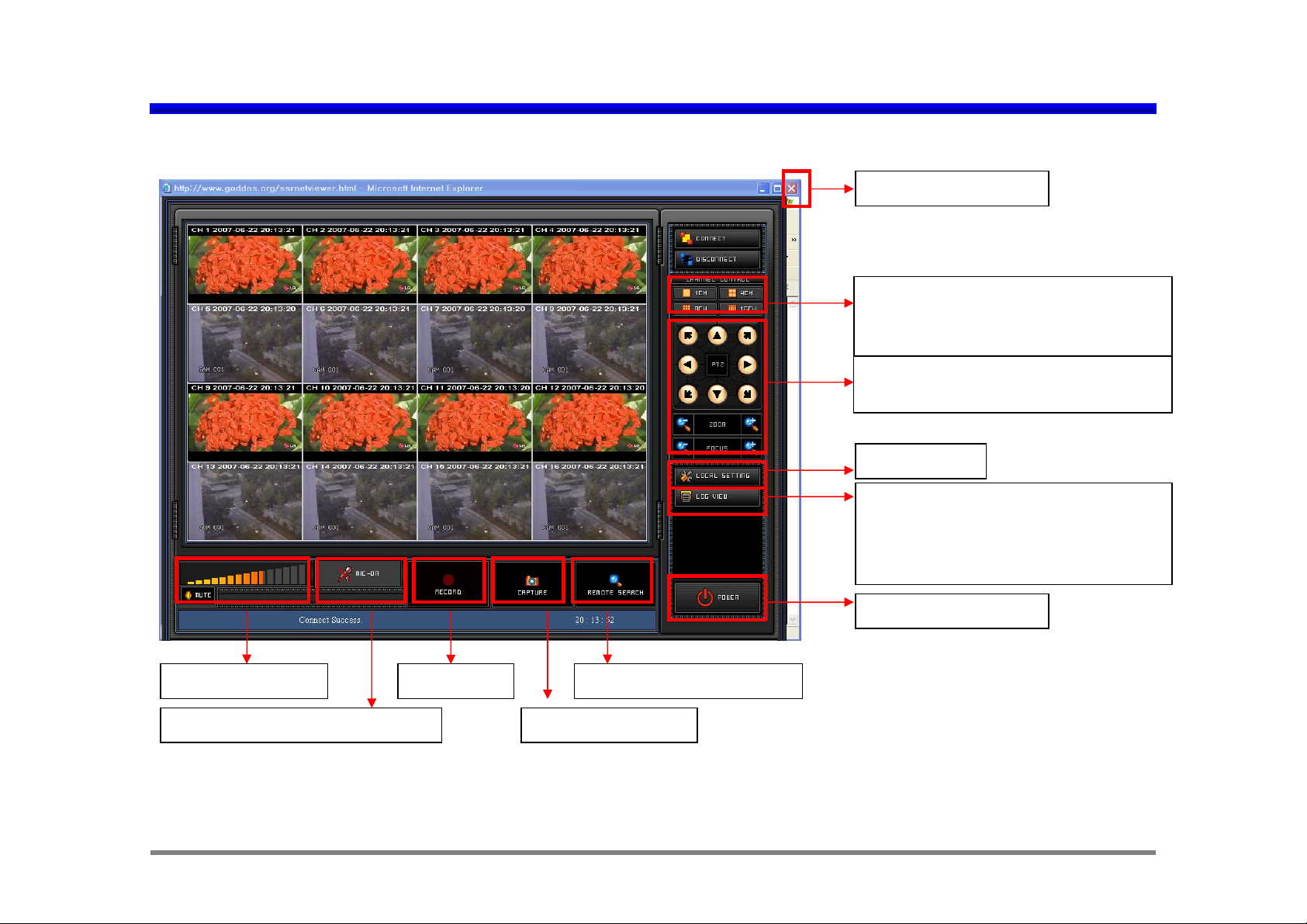
NetViewer Main GUI in IE
< Main GUI and live picture display in IE viewer >
Exit NetViewer in IE.
Display Channel Selection
If single channel which has audio
is selected, user can hear the audio.
PTZ camera Control.
(PAN/ TILT/ ZOOM/ FOCUS)
Local Setting
Log Data View
(Data path is C:\DVRBACKUP\
EventLog\20070606
\20070606184010.log)
Volume Control
Two way Audio communication Capture and Print
* In order to listen to audio, single channel with audio should be selected.
Playback and DownloadLocal Save
Exit NetViewer in IE.
Jun. 22, 2007
Page 6

< Local Setting >
NetViewer Local setting and Log View in IE
< Local Setting: Please click “A” >
1. OSD On /OFF setting: Channel, Date/ Time OSD,
OSD color
2. Motion-Alarm Window:
If Motion Window Visible or Alarm Window Visible
is selected and if motion is detected or alarm is
triggerred in any channel of remote DVR, notification
A
B
window will be pop-up with sound.
If Motion Window Visible or Alarm Window Visible
isn’t selected, there is no pop-up with no sound.
But motion or alarm information will be displayed in
information window “B”.
3. Local Record Directory:
Default is C:\DVRBACKUP\
4. Version Display
5. Remote Firmware Upgrade
Remote motion or alarm notification mark
POP-UP window for remote motion or alarm notification
Jun. 22, 2007
Page 7

< Log View >
< Remote Search >
Log View & Remote Search in IE NetViewer
< Log View : Please click “B” >
Data path is C:\DVRBACKUP\ EventLog\
20070606 \20070606184010.log
B
< Remote Search : Please click >
First, select the year/ month/ date in calendar .
Second, click one of listed files of for playback or
1
2
3
4
5
6
C
download.
Then click “PLAY” for playback or click
“DOWNLOAD” for file download using FTP.
3
4
In order to stop “PLAY” or “DOWNLOAD”, can
be clicked.
* In order to move specific time much faster within
selected file, with time slide bar can be used.
6
C
1
2
5
Jun. 22, 2007
Page 8

CAPTURE/ SAVE Etc. in IE NetViewer
< CAPTURE, SAVE, Microphone ON and Volume Control >
Save
Still picture saving and Print function
Live or playback data can be stored in local PC. Default directory is C:\ DVRBACKUP\.
It can be changed in “Local Setting”.
For two way communication, microphone and speaker should be prepared both in PC and in DVR.
Volume Control. * In order to listen to audio, single channel with audio should be selected.
Print
Jun. 22, 2007
Page 9

2. CMS (Center Monitoring Software) in IE
1. Please write http://www.goddns.org/xp in Internet explorer for remote viewer.
xp
Exit NetViewer in IE.
Please click “CMS” for multi site DVR viewing
at the same time through IE.
Page 10

Connect Address Setting of CMS in IE
Please click “CONNECT” for CMS demo site accessing.
CMS Network Connection
CMS network connection consists of total “16 GROUP”. Each GROUP have Max “16 viewing channel “.
Each viewing channel can have different IP address.
It means that each viewing channel can be allocated to different 16ch DVR with different IP address.
In order to move other Group in 16 GROUP, “CONNECT” icon with selection of corresponding GROUP can be
pressed again after “DISCONNECT” icon pressing.
For example of GROUP editing for viewing channel,
(Suppose there are 4 sixteen CH DVR which have different IP address. Each sixteen CH DVR have sixteen CH picture.)
Jun. 22, 2007
Page 11

CMS IP setting Example in IE
Four viewing pictures of each sixteen CH DVR can be assigned like this;
< GROUP 1 display >
CH1 to CH4 of DVR1 -> CH1 to CH4 display position for “GROUP 1“display.
CH1 to CH4 of DVR2 -> CH5 to CH8 display position for “GROUP 1“display.
CH1 to CH4 of DVR3 -> CH9 to CH12 display position for “GROUP 1“display.
CH1 to CH4 of DVR4 -> CH13 to CH16 display position for “GROUP 1“display.
< GROUP 2 display >
CH5 to CH8 of DVR1 -> CH1 to CH4 display position for “GROUP 2“display.
CH5 to CH8 of DVR2 -> CH5 to CH8 display position for “GROUP 2“display.
CH5 to CH8 of DVR3 -> CH9 to CH12 display position for “GROUP 2“display.
CH5 to CH8 of DVR4 -> CH13 to CH16 display position for “GROUP 2“display.
< GROUP 3 display >
CH9 to CH12 of DVR1 -> CH1 to CH4 display position for “GROUP 3“display.
CH9 to CH12 of DVR2 -> CH5 to CH8 display position for “GROUP 3“display.
CH9 to CH12 of DVR3 -> CH9 to CH12 display position for “GROUP 3“display.
CH9 to CH12 of DVR4 -> CH13 to CH16 display position for “GROUP 3“display.
< GROUP 4 display >
CH13 to CH16 of DVR1 -> CH1 to CH4 display position for “GROUP 4“display.
CH13 to CH16 of DVR2 -> CH5 to CH8 display position for “GROUP 4“display.
CH13 to CH16 of DVR3 -> CH9 to CH12 display position for “GROUP 4“display.
CH13 to CH16 of DVR4 -> CH13 to CH16 display position for “GROUP 4“display.
Jun. 22, 2007
Page 12

CMS IP setting Example in IE
< GROUP 1 display picture setting example >
CH1 of
DVR 1
CH1 of
DVR 2
CH1 of
DVR 3
CH1 of
DVR 4
CH2 of
DVR 1
CH2 of
DVR 2
CH2 of
DVR 3
CH2 of
DVR 4
CH3 of
DVR 1
CH3 of
DVR 2
CH3 of
DVR 3
CH3 of
DVR 4
CH4 of
DVR 1
CH4 of
DVR 2
CH4 of
DVR 3
CH4 of
DVR 4
GROUP 1
< GROUP 4 display picture setting example >
CH13 of
DVR 1
CH13 of
DVR 2
CH13 of
DVR 3
CH13 of
DVR 4
CH14 of
DVR 1
CH14 of
DVR 2
CH14 of
DVR 3
CH14 of
DVR 4
CH15 of
DVR 1
CH15 of
DVR 2
CH15 of
DVR 3
CH15 of
DVR 4
CH16 of
DVR 1
CH16 of
DVR 2
CH16 of
DVR 3
CH16 of
DVR 4
GROUP 4
Jun. 22, 2007
Page 13

CMS IP setting Example in IE
< Editing example for GROUP 1 display picture setting >
GROUP 1
DVR1
DVR1 IP address
10000
ADMIN
********
CH1
GROUP 1
View CHUSERPORTADDRESSNAME
CH1ADMIN10000DVR1 IP addr es sDVR1
CH4ADMIN10000DVR1 IP addressDVR1
CH5ADMIN10000DVR2 IP addressDVR2
CH8ADMIN10000DVR2 IP addressDVR2
CH9ADMIN10000DVR3 IP addressDVR3
CH11ADMIN10000DVR3 IP addressDVR3
CH13ADMIN10000DVR4 IP addressDVR4
CH16ADMIN10000DVR4 IP addressDVR4
Jun. 22, 2007
Page 14

CMS IP setting Example in IE
When this “CONNECT” icon, is clicked, below “CONNECT ADDRESS” window will be appeared.
< How to use ”CONNECT, ADD, DELETE and MODIFY” in “CONNECT ADDRESS” >
1
“CONNECT ADDRESS”
1
“CONNECT”
“ADD”
“DELETE”
“MODIFY”
Registered CONNECT ADDRESS
A) How to add “CONNECT ADDRESS” (“ADD” )
- NAME: Any name (DVR nickname)
- ADDRESS: The IP address of DVR which want to access can be written in “ADDRESS”.
This IP address can be confirmed in “IP address of NETWORK menu” in DVR.
- PORT number: default is “10000”. ( It is different according to network environment.)
(Port should be opened from 10000 to 10020.) But it can be adjustable with other port number soon.
- USER is assigned as “admin” initially.
- PASSWORD: The “password of DVR” which want to access should be input here.
The requested password is same as the DVR password. (Default is “11111111”, eight one)
Jun. 22, 2007
Page 15

CMS IP setting Example in IE
If “ADD” is clicked after filling all the parameter, new “CONNECT ADDRESS” will be registered in address list.
One of easier way to add “CONNECT ADDRESS” is to click “ADD” after modification of “CONNECT ADDRESS”
using “MODIFY”.
B) How to delete “CONNECT ADDRESS” (“DELETE” )
First, select one of listed “registered CONNECT ADDRESS” which want to remove and then click
“DELETE” to remove it.
C) How to modify “CONNECT ADDRESS”
First, select one of listed “registered CONNECT ADDRESS” which want to modify and modify one of
NAME, ADDRESS usually. Then click “MODIFY” to modify it.
< How to connect network. >
Select one of listed “registered CONNECT ADDRESS” which want to connect.
If network connection is succeeded, below initial “CMS Software” will be appeared in PC with message
“ Connect Success” in bottom of CMS software GUI.
Jun. 22, 2007
Page 16

CMS (Center Monitoring Software) main GUI in IE
1
2
3
NOTE:
Most of functions like No. 4
Local setting, No. 5 Log view
4
and so on is same as
NetViewer. Please confer the
9 10 11 12
5
explanation of NetViewer f or
details.
7
8
Icon DescriptionNo.
Network Connection and Disconnection1
Display Channel Sel ection 2
PTZ control 3
Local Setting 4
Icon DescriptionNo.
7
Audio Volume Control
8
Audio Mute ON/ OFF
9
Microphone ON/OFF for two way audio communication.
10
Recording in local PC.
6
Log View 5
Program Exit6
11
Capture ( picture printing and saving.)
12
Remote Searching
Jun. 22, 2007
 Loading...