

Page 1
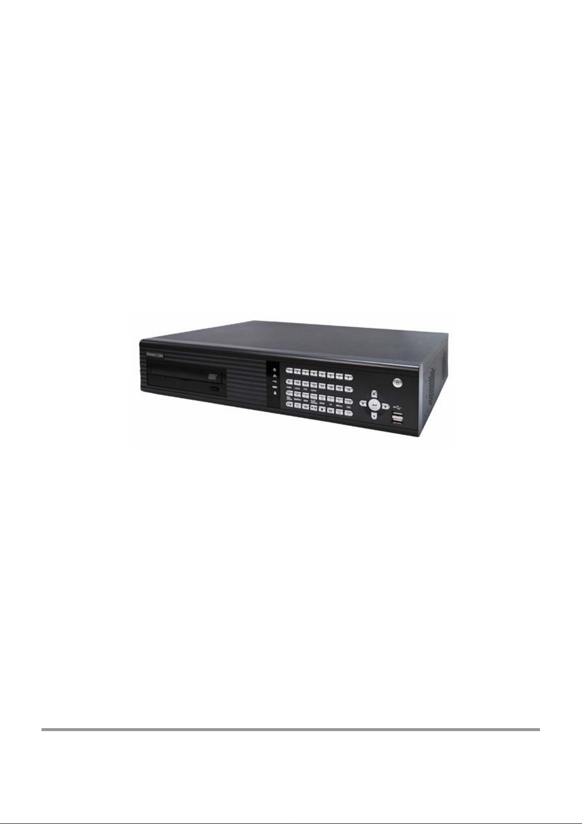
MPEG-4 DVR User’s Manual
(Model: 16CH MPEG-4 DVR)
This user’s manual is subject to change without any previou s notice by
function upgrade or addition.
Page 2
SAFETY PRECAUTIONS
CAUTION
RISK OF ELECTRIC SHOCK DO NOT OPEN
CAUTION: TO REDUCE THE RISK OF ELECTRIC SHOCK, DO NOT REMOVE COVER (OR BACK)
NO USER-SERVICEABLE PARTS INSIDE. REFER SERVI CING TO QUALIFIED SERVICE
PERSONNEL.
This label may appear on the rear of the unit due to space limitations.
The lightning flash with arrow point symbol, within an equilateral triangle, is
intended to alert the user to the presence of uninsulated “dangerous voltage”
within the product’s enclosure that may be of sufficient magnitude to
constitute a risk of electric shock to persons.
The exclamation point within an equilateral triangle is intended to alert the
user to the presence of importance operating and maintenance (servicing)
instructions in the literature accompanying the appliance.
Warning
To reduce the risk of fire or electric shock, Do not expose this product to rain or moisture.
Do not insert any metallic object through ventilation grills.
Power disconnect : Units with or without ON-OFF switches have power
supplied to the unit whenever the power cord is inserted into the main source;
However, the unit is operational only when the ON-OFF switch is in the ON
position. To disconnect it from the main source, you have to disconnect the
Power cord.
Page 3

FCC COMPLIANCE STATEMENT
A CLASS A computing device subject to certification by the Commission shall be identified pursuant to
Par 2.925 et Seq of the chapter. In addition, the label shall include the following statement:
This device complies with Part 15 of FCC Rules.
Operation is subject to the following two conditions:
(1)This device may not cause harmful interference, and
(2)This device must accept any interference received,
including interference that may cause undesired operation.
Where a device is constructed in two or more sections connected by wires and marked together, the
statement specified in this Section is required to be affixed only to the main control unit.
The users manual or instruction manual for the EUT shall contain the following statement or equivalent.
Caution : Changes or Modifications not expressly approved by the party responsible for compliance could
void the users authority to operate the equipment.
If the EUT requires accessories such as special shield cables and/or connectors to enable compliance
with emission limits, the instruction manual for the EUT shall include appropriate instruction on the first
page of the text concerned with the installation of the device that these special accessories must be used
with the device. It is the responsibility of the user to use the needed special accessories supplied with the
equipment.
For a CLASS A digital device or peripheral, the instruction furnished the user shall include the following or
Similar statement placed in a prominent location in the text of the manual.
Note : This equipment has been tested and found to comply with the limits for a CLASS a digital device,
pursuant to Part 15 of FCC Rules. These limits are designed to provide reasonable protection against
harmful interference when the equipment is operated in a commercial environment, This equipment
Generates, uses and can radiate radio frequency energy and, if not in stalled and used in accordance
with the instruction manual, may cause harmful interference to radio communications. Operation of the
this equipment in a residential area is likely to cause harmful interference in which cause the user will
be required to correct the interference at his own expense.
Page 4

Before Starting Your DVR Operation
This document is a basic manual for the DVR users.
This manual describes the appearance and name of products, how to configure the
system program, and how to use the system.
Before using DVR, a user should read the contents of user manual, and then deal with
the product considering the precautions defined in the manual.
To open the system case and touch the inner parts for corrective maintenance, a user
should contact the place where he/she purchased the products to get the help from
expert.
In addition, if there is any question for use or any damage on the product, please contact
call the place where he/she purchased the products.
Precautions for safety (User should observe)
1. Precautions for installation
z Install the product on a flat floor not closed and retain the distance of more than 15
cm from the rear panel to the wall.
z Install the product on a well-ventilated place.
z Keep it away from strong magnetism or electromagnetic wave.
z Installing it near radio equipment such as TV and radio may cause a fault.
z Do not install it on a place that is exposed directly to the sun or contains lots of heat
such as near a heating apparatus.
z Do not install it on a cold place.
z Place the equipment or tools in the site remote from a busy road so that people are
not hurt.
z Do not install it on a place where there is severe vibration, much humidity or soot.
z Should use the product in the rated voltage (The equipment is used as both 110V
and 220V, but it is set to 220V for delivery. It is possible to adjust it with the
changeover switch on the rear panel.)
z Connect it to the outlet with the ground terminal.
z Discard the vinyl bag well. (It is dangerous to put it on the head.)
Page 5

2. Precautions for use
z For the repair, contact the company or the place where you purchased the product.
z Read the user manual before using the product.
z Do not open the cover at your discretion because there are parts sensitive to the
environment within the equipment.
z Arrange the power cord safely and do not touch it with wet hands.
z Do not use a loose outlet or a damaged power cable.
z Do not use benzene, thinner and alcohol for cleaning. They may deform the product.
z Do not touch the exposed terminal.
z For the power-off of system, normally turn off the power of the program and then,
power off the peripherals. (Do not power it off with the power button on the front panel
of body.)
z Be careful to prevent a conductive object from falling into a hole that was punched for
ventilation.
z Do not dissemble and remodel the product.
z Do not place a heavy thing on the body.
z Do not give a shock during the movement of equipment.
z If you use the product in the state of s moke or smell emitted, it may cause a fire or an
electric shock. For this case, immediately block the power switch and contact the
company or the place where you purchased the product to consult it with a special
technician.
This user’s manual is subject to change without any notice by function upgrade and
so on.
Page 6

Table of Contents
I. Introduction
1. Package Contents ------------------------------------------ P 2
2. Features ---------------------------------------------------------- P 3
3. Front Panel and Rear Panel Connection -------------- P 4
II. Installation
1. Front Panel ------------------------------------------------------ P 5
2. Rear Panel ----------------------------------------------------- P 9
3. Remote Controller ------------------------------------------ P11
4. Menu Tree ------------------------------------------------------ P13
III. Main MENU Programming
1. Overview Main Menu ---------------------------------------- P 14
2. SYSTEM SETUP ----------------------------------------------- P 15
3. DISPLAY SETUP ---------------------------------------------- P 21
4. RECORDING SETUP ----------------------------------------- P 25
5. EVENT SETUP ------------------------------------------------- P 27
6. SCHEDULE ------------------------------------------------- --- P 30
7. NETWORK SETUP ---------------------------------------- -- P 33
8. COPY ----------------------------------------------------------- - P 36
* File Player Program
9. HDD INFORMATION ----------------------------------------- P 45
10. CAMERA SETTING ------------------------------------------ P 47
11. SEARCHING and PLAYBACK ---------------------------- P 50
12. Live DISPLAY Mode ----------------------------------------- P 53
13. RECORDING Mode ------------------------------------------ P 55
14. PTZ control Procedure ------------------------------------- P 56
IV. Software Upgrade Procedure ------------------------------ P 57
APPENDIX 1. Specification
2. Pin Description of connectors
3. HDD Capacity Calculation Table
1
Page 7
I. Introduction
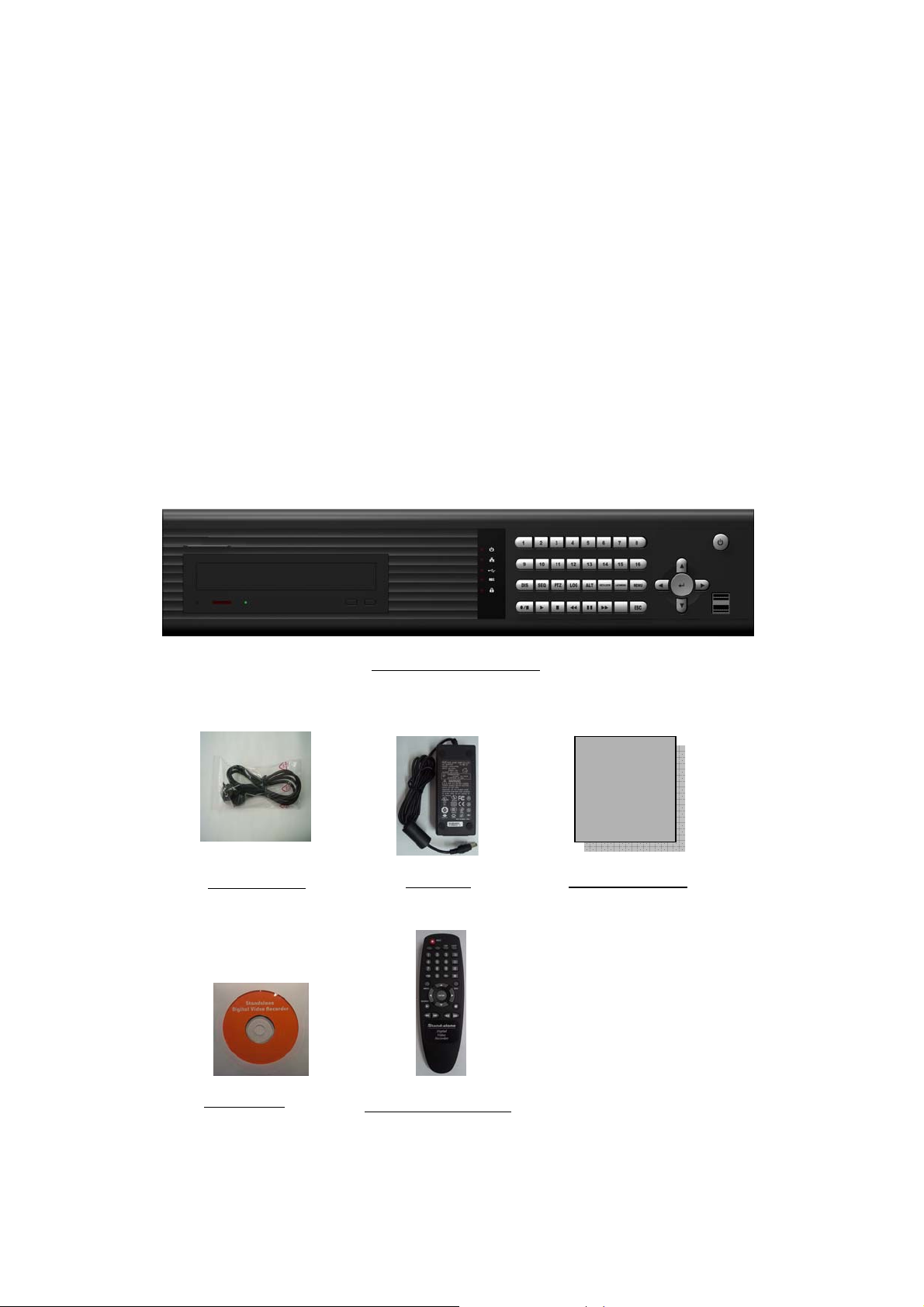
1. Package Content
After purchasing DVR product, unpack it at first and unload it on a flat
floor or a place where it is to be located. Then, verify that the following contents are
contained.
z 16CH MPEG-4 DVR
z Adapter (12V/5.8A)
z Power cord
z User’s manual
z Install CD
z Remote controller (included two battery)
Power code
Install CD
16CH MPEG-4 DVR
Adapter
Remote controller
User’s Manual
User’s Manual
2
Page 8

2. Features
This Embedded Linux Stand-Alone DVR can record 16 channel video and 16ch audio
at the same time. It provides playback, live display, back-up and network function
while it is in recording mode. And it also offers the following features:
16 Composite video Input/ 16 Loop-Through Video output Connectors
- Compatible with Color (NTSC or PAL) and B&W (CCIR and EIA-170) Video
3 Composite video output/ 1 S-Video output/ 1 VGA output Connectors
16 channel audio Inputs/ 2 channel audio outputs
High quality video Display and Recording
- NTSC (720x480), PAL (720x576) real time display
Compression: MPEG-4 for video, G.723 for audio
Multiple Search Categories (Date/Time, Motion, Alarm, Manual)
Real time recording and Playback support
- 480 Fps recording and playback for NTSC at CIF image (400 Fps for PAL)
- Pre-Recording by event
Continuous Recording in Disk Overwrite Mode
Pentaplex: Simultaneously Live, Record, Playback, back-up and Network
COPY
- CD-RW (Option: DVD) Back up and USB 2.0 USB Memory Drive support
User-friendly GUI Menu, Mouse Operation
PTZ camera control support in local and remote area
16 Alarm input Connections, 4 relay output connection
Network Function
- Static IP as well as Dynamic IP (DHCP, Floating IP) and DDNS support
- Live or Recorded Video Accessing via Ethernet
- Remote Configuration.
- Multi-user accessing support/ CMS (Center Monitoring Software) support
- Two way audio transmission, Remote Event (Alarm, Motion) Notification
Audio Recording and Playback
- 16ch audio recording/ 1ch audio playback for selected audio channel.
3
Page 9
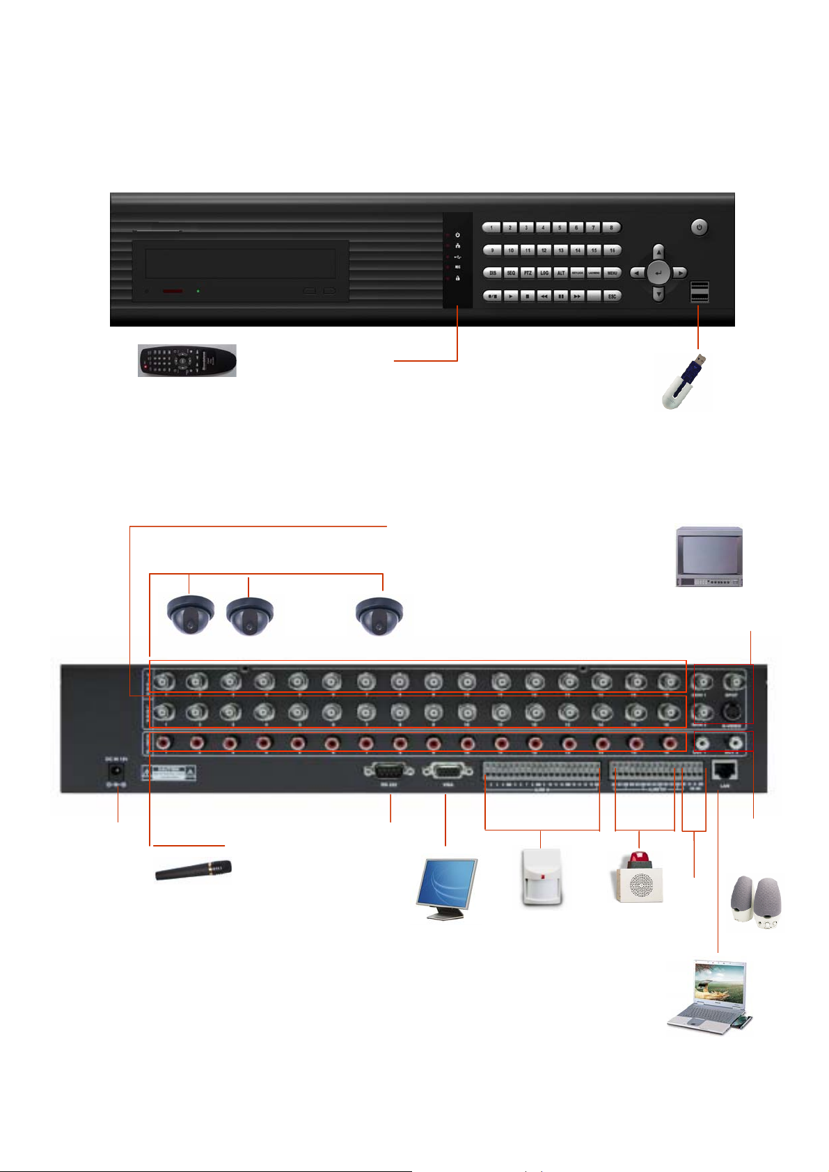
3. Front Panel and Rear Panel Connection
Remote Controller
Camera (1~16CH)
•••••
USB Memory Driver
16 Loop-Through output
3 CVBS/
1 S-Video
Adapter
(12V, 6.7A)
16 Audio
Input
RS232
1 VGA
4
Sensor
Input
(Ethernet)
Two
Audio
Output
PTZ
Alarm
Output
LAN
Page 10
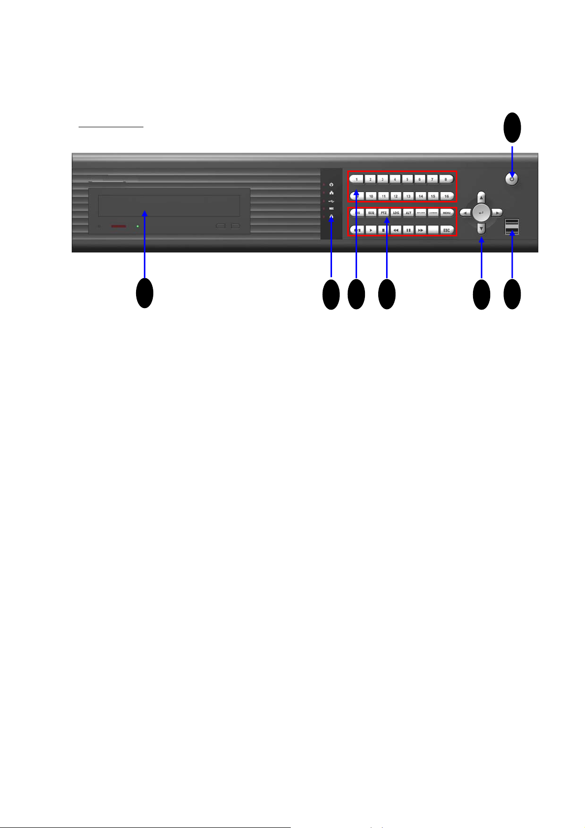
II. INSTALLATION
Front Panel
1
2
3 4
1. CD Tray
This can be used for backup media. According to option requirement, DVD also can
be mounted. can be used as backup media
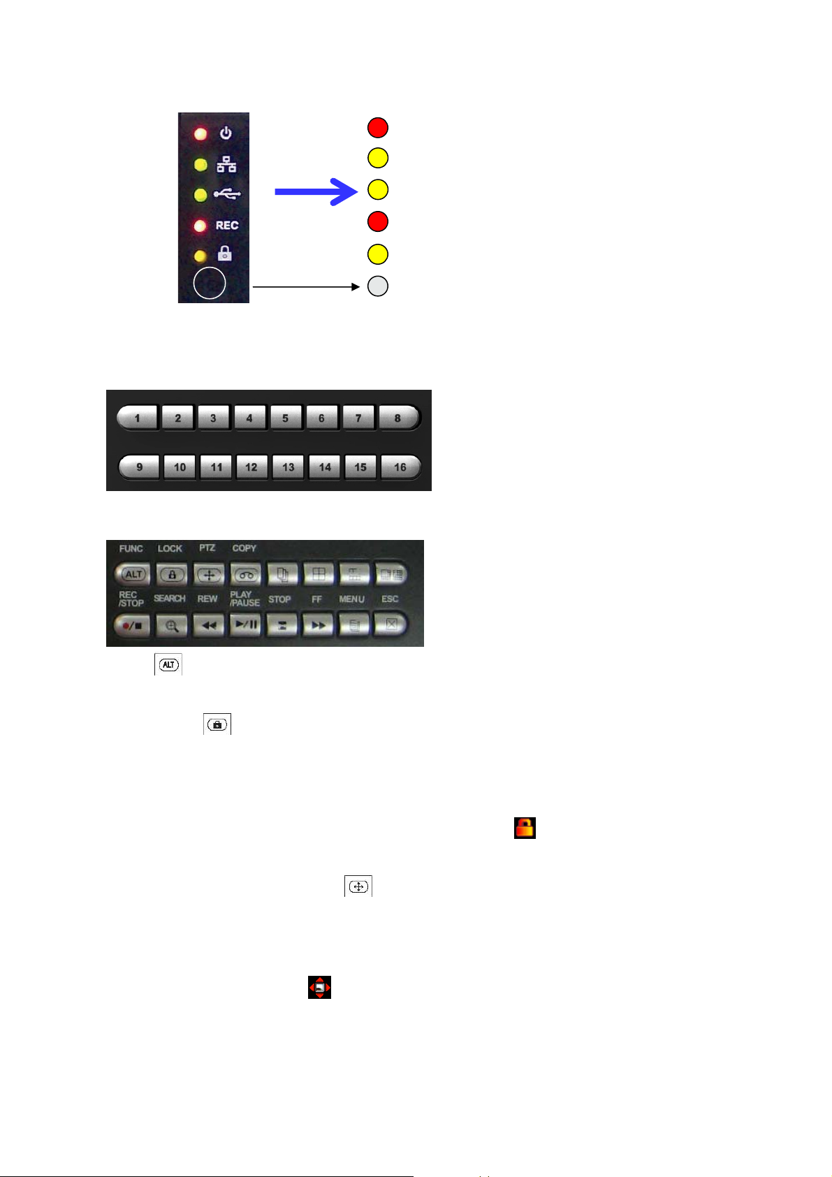
2. LED Indicators
6
5
7
1) POWER LED
This red LED turns “ON” when Power is “ON”.
2) NETWORK indication LED
This green LED will turn “ON”, while data through network is transmitting.
3) COPY LED
This green LED will turn “ON” during data COPY through CD-RW or USB Memory
driver.
4) REC
This red LED will turn “ON” during recording.
5) KEY LOCK
This yellow LED will turn “ON” while LOCK button is working.
6) Remote Controller receiver.
Remote controller sensor input window
5
Page 11
POWER
NETWORK
COPY
REC
KEY LOCK
REMOCON
3. Channel Selection buttons for single channel display
Channel selection button from CH1 to CH16 can be used to display given channel
on monitor.
4. Function buttons
1) ALT
This button is reserved for future use.
2) LOCK
In order for only authorized person to operate buttons in front panel, this LOCK button
can be utilized. If this button is pressed, all of buttons in front panel are not operated at
the same time yellow LOCK LED ON. To release button locking, password will be just
requested after pressing LOCK button. If correct password is input, button LOCK will be
released. When DVR is under key lock mode, this icon will be appeared on the left
top corner of monitor.
3) PTZ (Pan, Tilt and Zooming)
The camera (s) with panning, tilting and zooming function would be connected with one
and some of video inputs of rear panel of DVR. In order to control PTZ function of the
camera, PTZ button is pressed first. An then direction button for panning and tilt can be
pressed, ▶▶and ◀◀ for zooming in/ out can be used in PTZ mode. When DVR is
under PTZ mode, this icon will be appeared on left top corner of monitor.
6
Page 12

4) COPY button (Backup)
This COPY button can be used to retrieve some of recorded files into backup media like
USB memory drive or CD/ DVR after searching recorded files. According to backup
media, Icon (CD or DVD) or (USB memory drive) will be appeared on the left
top corner of monitor.
5) (Sequential Display button)
If this button is pressed under given video display mode, each video display mode is
switched sequentially. For example, if this button is pressed in QUAD mode, QUAD
picture is switched sequentially from CH1-4, CH5-8 to CH13-16.
6) (Display selection button)
Whenever these button is pressed, display mode can be changed f rom QUAD, 9CH to
16CH display mode. Whenever QUAD button is pressed, displaying picture will be
changed from CH1-4 to CH5-8, CH9-12 and CH13-16. Whenever button is pressed,
displaying picture will be changed from CH1-8 to CH9-16. This button shows 16
picture in monitor.
7) REC/ STOP button
REC button is pressed to start recording and to stop recording again. This is toggle
button. When DVR is under recording mode, this icon will be appeared on each
cameo of each channel.
8) Search button
This can be used to find out proper recorded file for playback or copy (backup). Searching
list can be displayed by pressing this button.
9) REW
This button can be used for high speed backward playback. It support 2 to 16 times
playback speed.
10) PLAY button and 11) STOP button
If PLAY
(▶) is pressed, playback picture will be frozen. If it is pressed again, playback
will be restarted. This button is for picture pause and play. To stop playback,
STOP button is used.
12) FF
Press FF button to do high speed forward playback. It support 2 to 16 times playback
speed.
13) MENU
MENU
button is pressed to enter menu system.
14) ESC
ESC button is used to return upper menu.
7
Page 13
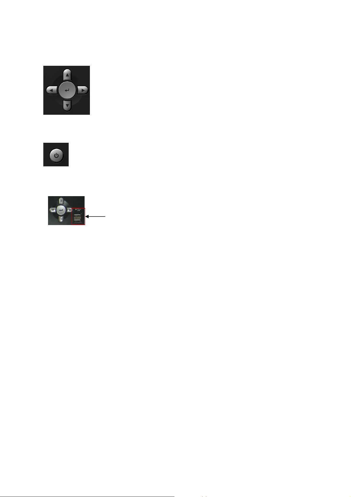
5. Direction button and Enter Button
Direction buttons are used to move LEFT, RIGHT, UP and DOWN in
menu.
They also can be used to input password. ENTER button is used to save
parameter, to select parameter in the menu. And also in playback it is
used to select one of listed file for playback after searching recorded files
by all, time, alarm, motion, manual and so on.
6. Power Button (Power On/ Off button)
This Power button can be pressed to turn off DVR power. When this button is
pressed, password is requested. When right password is input to DVR, DVR
power will be turned off.
7. USB 2.0 connector
Two USB Connectors.
8
Page 14
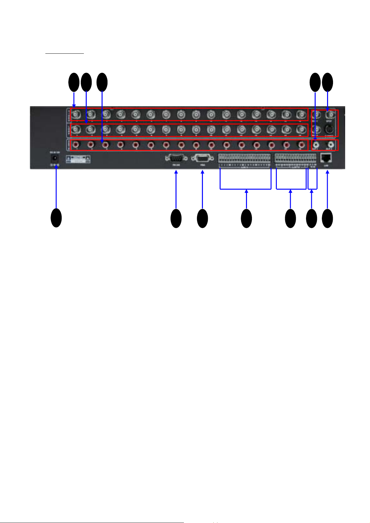
Rear Panel
2 3 54 6
1
7
98 1110 12
1. Power Input (from Adapter)
Connect the adapter to the DVR for DC power supply. (DC 12V/5.8A).
2. 16CH Video Input: 16 channel composite video inputs with BNC connectors
Since this DVR automatically detects video format (NTSC or PAL) as soon as power is
ON, NTSC or PAL video sources can be connected in DVR. But NTSC and PAL video
sources for 16CH video inputs can not be mixed. If they are mixed, DVR can’ not be
operated properly.
3. 16CH Loop through outputs: 16 channel composite video outputs with D-SUB
connectors. If the connection of loop-through video outputs into another video
equipments is requested, 16CH Loop-Through outputs can be utilized for it. If loopthrough video outputs will be connected to another video equipments, 75 Ohm
termination switch should be “OFF”. Then, another video equipments should be 75 ohm
terminated.
4. And 5. 16CH Audio input (RCA) and 2CH Audio Output (RCA)
Unbalanced audio signal input and output with RCA jack. Connect the audio source to
audio input, audio output to your amplifier because the DVR don’t amplify audio output.
A speaker with an amplifier will be needed for audio playback.. The audio input can be
from an amplified source or directly from a microphone.
9
Page 15

6. 3CH composite Video Output and 1 S-Video Output
Two video output (MON1 and MON2) and one S-Video are used to monitor live,
playback pictures. They are same video output. The other is used to monitor SPOT
output which displays all of connected video channels sequentially.
7. VGA Output
VGA output can be connected to LCD monitor or CRT monitor with progressive scan
directly which can receive analog R, G, B and synchronization signals.
8. RS232C (It can be utilized for future option.)
9. And 10. Alarm input and relay output:
(16 alarm inputs and 4 relay output with NO, NC)
To make secure connections on the Alarm Connector Strip, press and hold the button
and insert the wire in the hole below of connector pin. After releasing the pin, pull
gently on the wire to make certain it is connected. To disconnect a wire, press and
hold the connector pin above the wire and pull out the wire.
16 Alarm Inputs: 1,2,3,4,…, 16,G(Ground)
You can use external devices to signal the DVR responding to events. Mechanical or
electrical switches can be wired to the Alarm Inputs and GND (Ground) connectors.
The threshold voltage is 4.3V and should be stable at least 0.5 seconds to be detected.
G (Ground), COM (common): G is same as common.
Connect the ground side of the Alarm input to G (Ground). Connect the ground side of
relay output to COM connector.
4 Relay output:
4 relay output with NO or NC can be sent to external device. You can select NO or NC
, according to characteristic of mechanical or electrical switch.
11. RS485: For camera pan and tilting control
PTZ cameras can be controlled remotely through this RS485 port. The RS485
connector can be used to control PTZ (pan, tilt, zoom) cameras. Connect RX+, RX- of
the control system to the TX+, TX- (respectively) of the DVR.
12. Ethernet Port: RJ45 jack
Connect a Cat5 cable with an RJ-45 jack to the DVR connector. Remote PC viewer
software via network enable you to access live viewing, searching and other available
functions.
10
Page 16
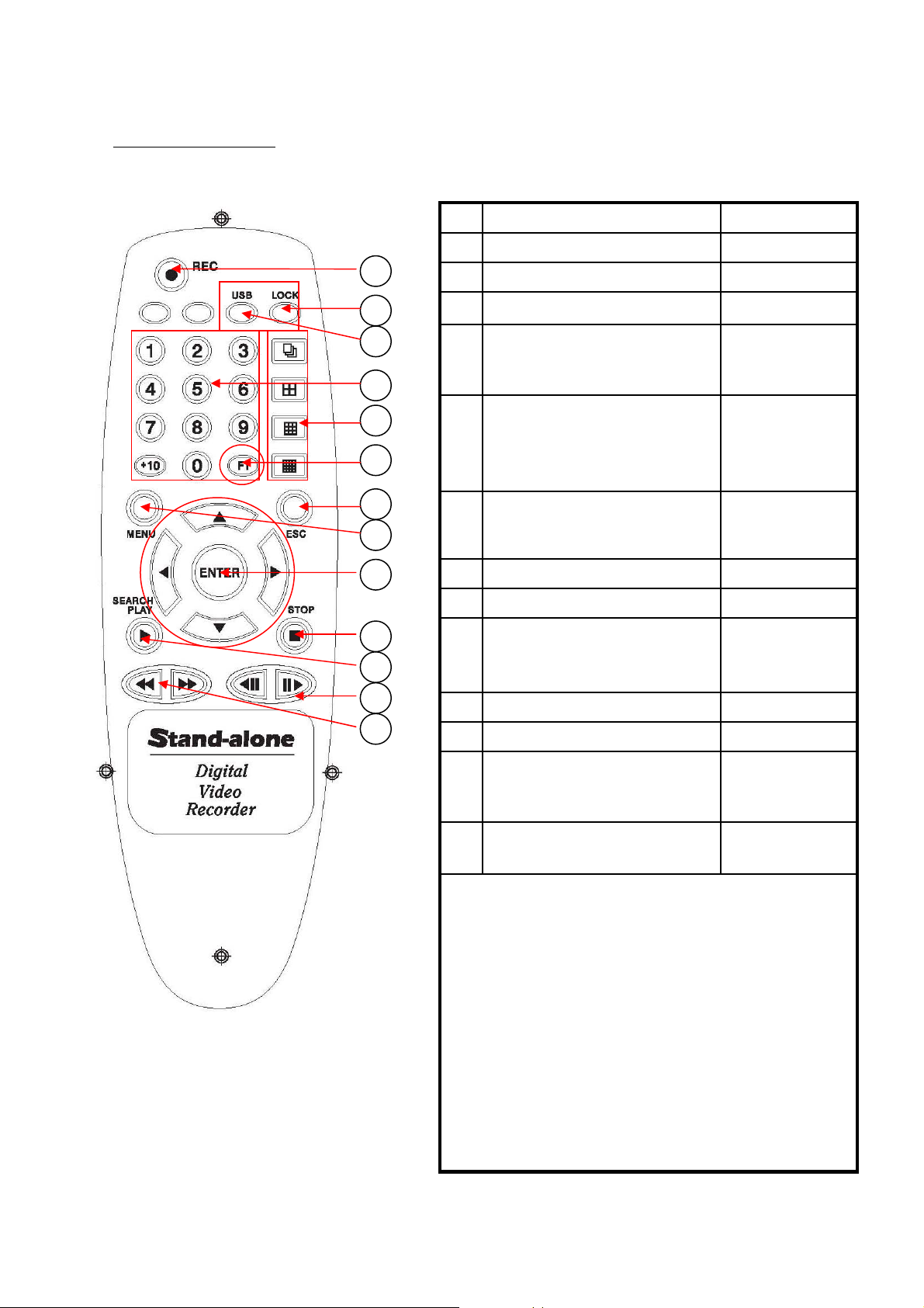
Remote Controller
< Remote Controller buttons >
10
11
12
13
< Button Description >
Button NameDescriptionNo
RECRecording Start/ Stop button1
1
2
3
Video CH selection buttons4
4
5
5
6
7
8
1) Sequential display button
2) QUAD display button
3) 9 picture display button
4) 16 picture display button
6
this button, audio channel for
speaker can be selected.
9
9
1) UP (▲) 2) DOWN (▼)
3) LEFT (◀) 4) RIGHT (▶)
5) ENTER
LOCKButton LOCK Enable/Disable2
USB/ CDCOPY Start button3
1,2,3,…,0, +10
(Password
Number Input)
Video Picture
Display mode
FunctionIf menu button is pressed after
ESCMovement to upper menu7
MENUMovement to menu mode8
Direction and
ENTER buttons
STOPPlayback Stop button10
Search/ PLAYPlayback Start button11
PAUSE/ 1 field movement
12
backward or forward.
Schedule recording removal
13
Schedule recording reservation
< Special Function using F1 button >
1. Audio Channel selection for speaker output
In live display mode or playback mode, if MENU button
is pressed after F1 button pressing, audio channel can
be selected.
2. Motion Tracking Display On/ Off
(It is limited in only MOTION recording channels)
If ESC button is pressed after F1 button pressing,
motion tracking will be displayed.
3. Remote Controller ID Selection
If No button from1 to 16 is pressed after F1 button
pressing, the DVR with corresponding Remote
Controller ID can selected.
11
FF, REWFast Playback buttons
Page 17
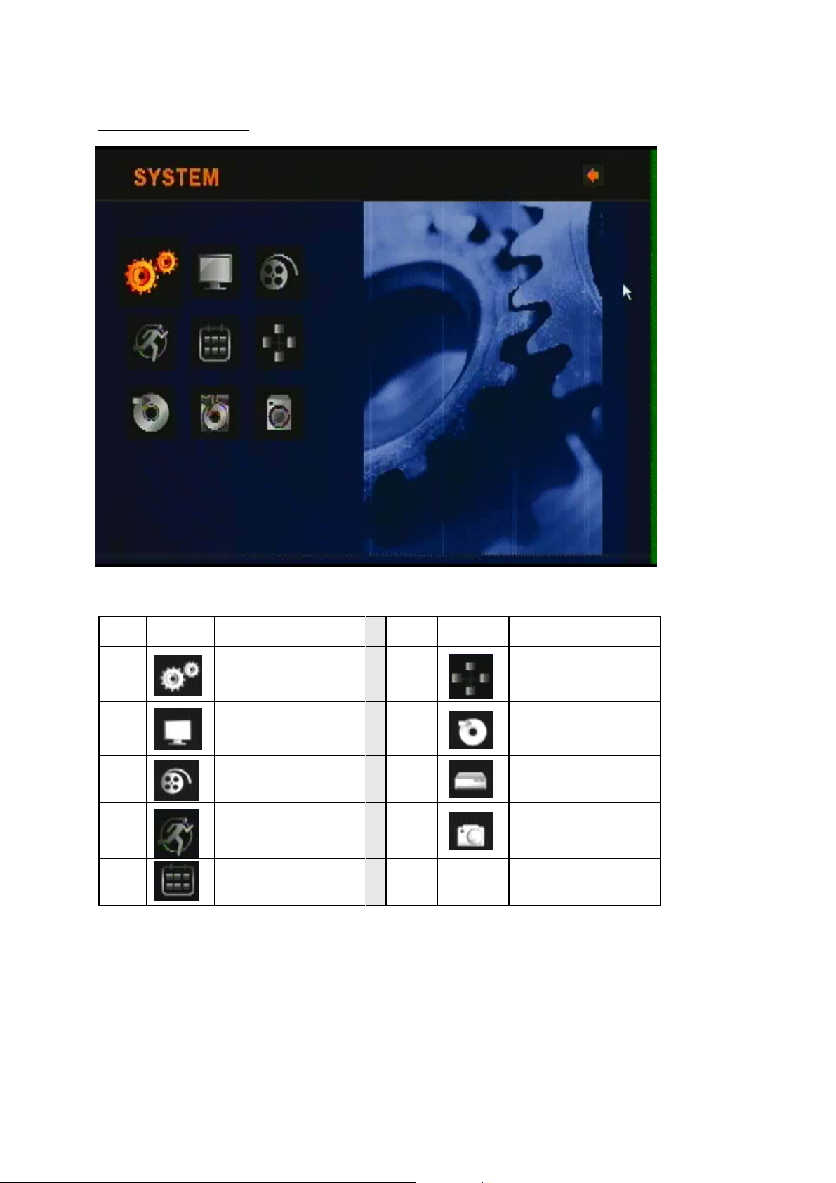
Main Menu Display
Menu Icons
NAMEICONNo.
SYSTEM1
DISPLAY2
RECORDING3
EVENT4
No. NAMEICON
6
7
8
9
NETWORK
COPY
HDD
CAMERA
SCHEDULE5
12
Page 18
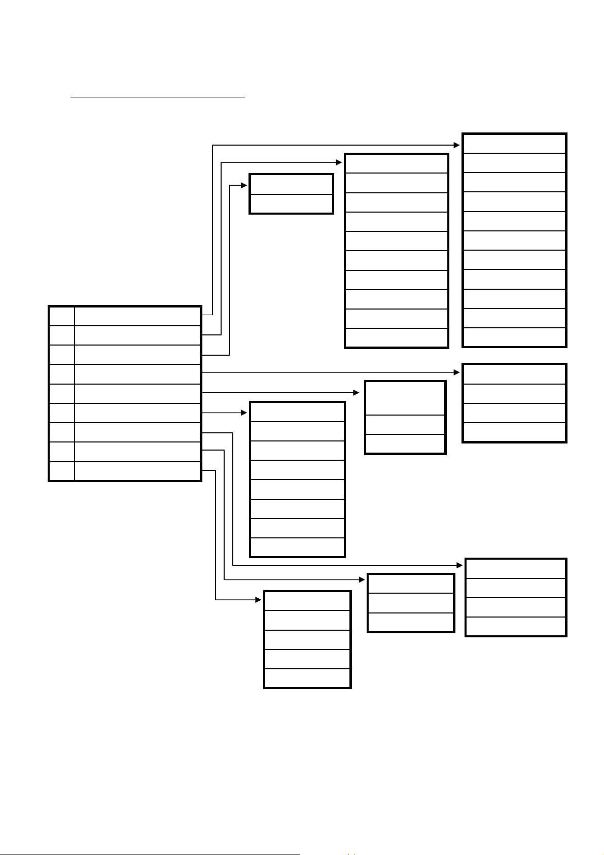
16CH MPEG-4 DVR Menu Tree
LANGUAGE
SEQ DWELL
STOP KEY
REC SETTING
SYSTEM1
DISPLAY2
RECORD3
EVENT4
SCHEDULE5
NETWORK6
COPY7
HDD 8
CONNECT
IP ADDRESS
SUBNET
SPOT DWELL
TIME/DATE OSD
CAM NO OSD
VIDEO LOSS OSD
POP-UP DISPLAY
ADJUST CH
PRIVATE
CH QUALITY SET
QUALITY RESET
SCHEDULE
ON/ OFF
WEEKLY
DAILY
VIDEO FORMAT
PASSWORD
ADMIN LOCK
REMOTE CONT ID
TIME FORMAT
DATE FORMAT
DATE/ TIME SET
VERSION NO.
FACTORY RESET
UPGRADE
SETUP1
SETUP2
MOTION AREA CH
MOTION AREA
CAMERA9
GATEWAY
DNS
PORT
TIME ZONE
NTP TIME SYNC
CAMERA NO
CAMERA ID
PTZ TYPE
PTZ ID
BAUD RATE
OVERWRITE
FORMAT HDD
INFO
DEVICE
BACKUP LOG
CD/DVD FORMAT
BACKUP INFO
13
Page 19
III. Main Menu Programming
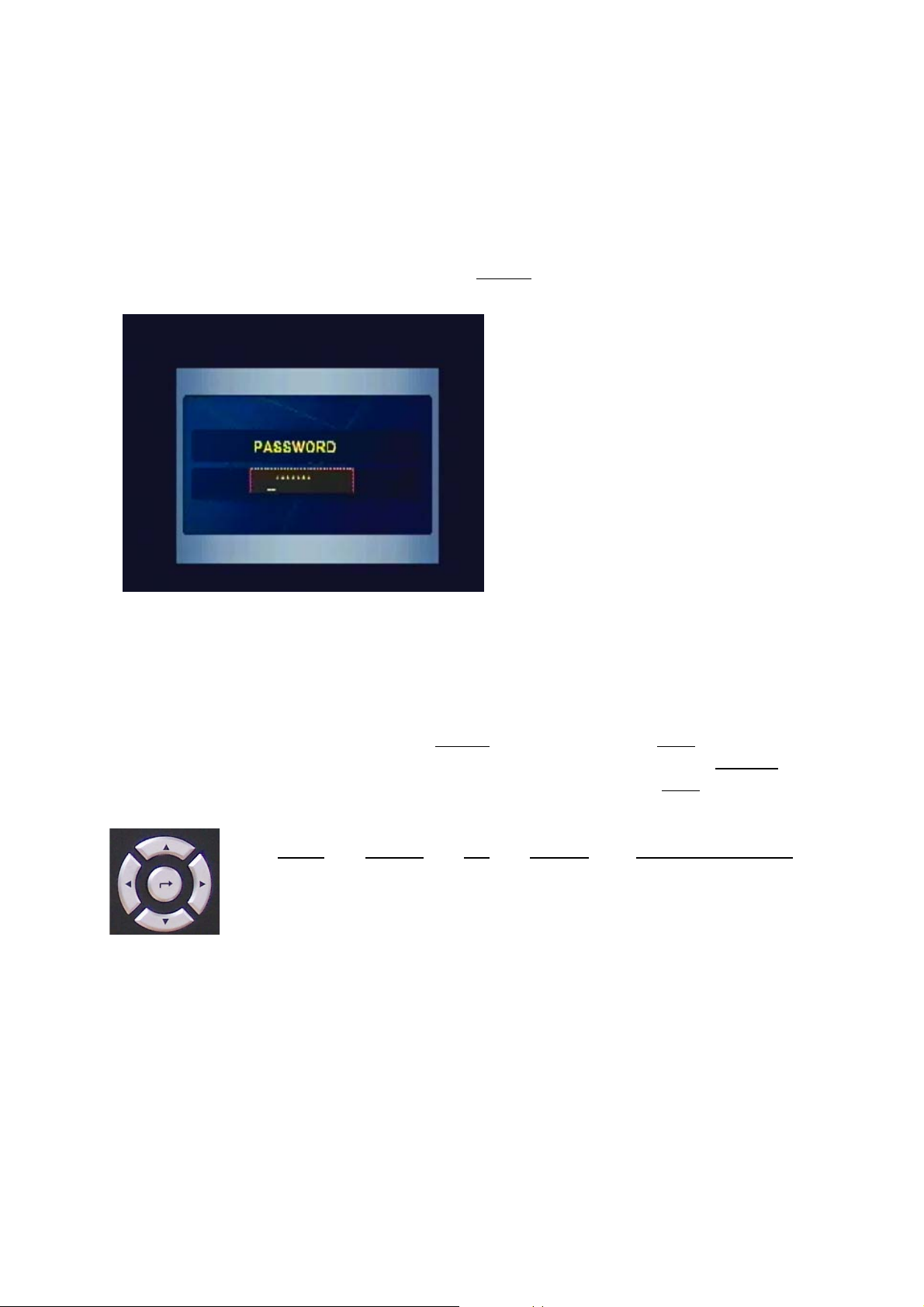
1. Overview Main Menu
Before using your DVR for the first time, you will want to establish the initial settings.
This includes setting items such as time and date, password, display, record mode,
network and so on.
In order to program Main Menu, first press MENU button of front panel in DVR.
If ADMIN LOCK is set as YES (factory default is YES), below figure will be appeared.
Then input password number using 1, 2, 3, … , 9 Channel Buttons (Factory default is
to press “1” button 8 times), and press ENTER button. MAIN MENU will be appeared.
NOTE:
To access the DVR Main Menu, press MENU. To escape MENU, ESC button can be
used. Buttons for movement in Menu are ◀ or ▶. Button for selection is ENTER
Button for increasing or decreasing setting value is ▲ or ▼. Press ESC to return to the
previous MENU after setting and to save the values of setup.
◀(LEFT
buttons.
), ▶(RIGHT), ▲(UP), ▼(DOWN) and ENTER (CENTER)
,
14
Page 20
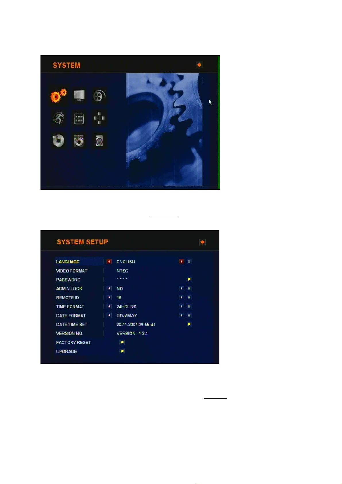
< MAIN MENU >
2. SYSTEM SETUP
To access SYSTEM SETUP, press ENTER button after moving highlight icon to
SYSTEM SETUP in MAIN MENU. Below menu will be appeared on monitor.
1) LANGUAGE : Language Selection
The language which can be displayed in Menu can be selected.
Whenever left or right button is pressed , supported language can be selected.
For language selection by graphical user interface, ENTER button can be pressed.
Below GUI for language selection will be appeared.
15
Page 21
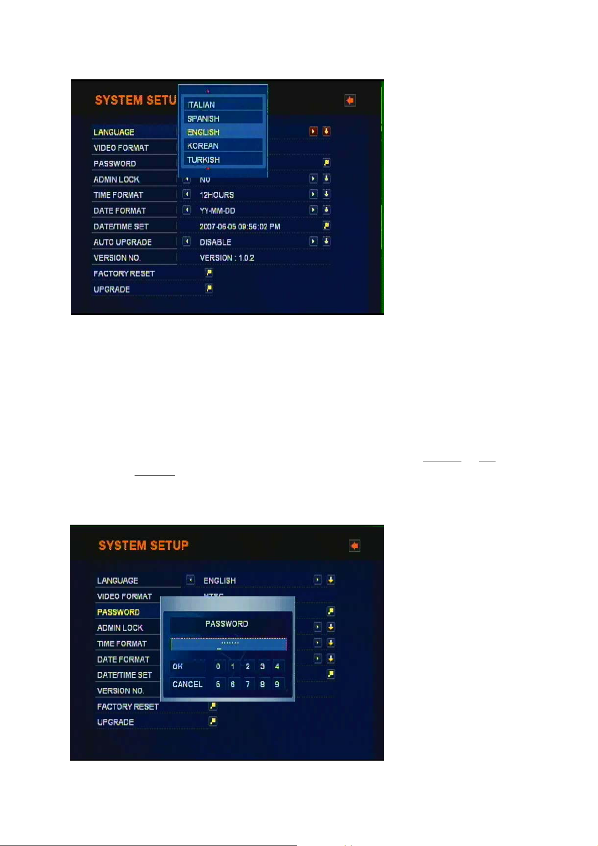
By using up or down button, supported language can be selected.
2) VIDEO FORMAT: NTSC/ PAL
Video format is automatically detected after power ON. The detected video information
will be displayed on VIDEO FORMAT. User don’t need to change video format.
It is recommended that power is “ON” after camera(s) connection for video
format recognition.
3) PASSWORD:
Move Highlight icon to PASSWORD in the SYSTEM Menu using DOWN or UP button .
And press ENTER button to change password. Then below “old password” window will
be appeared. Password can be changed using from 0 to 9 button.
NOTE: Factory Default is “11111111”, press number 1 button by eight times”.
16
Page 22

After inputting old password, input new password using from 0 to 9 button.
It needs to input new password again to confirm new password.
4) ADMIN LOCK: YES/ NO
Move Highlight icon to ADMIN LOCK in the SYSTEM Menu using DOWN or UP button .
If ADMIN LOCK is selected as YES by LEFT or RIGHT, password is requested
whenever entering menu. If NO, password isn’t requested.
5) Remote Cont ID: OFF, ID1, ID2, …, ID16
When multiple DVR are installed in same location and a specific DVR among them is
requested to control by one Remote Controller, Remote Cont ID can be utilized by
setting proper Remote Cont ID into each DVR. In order to control specific DVR by one
17
Page 23

remote controller, corresponding number button for Remote Cont ID can pressed just
after pressing F1 button. If specific DVR with corresponding Remote ID is selected,
the ICON for remote controller ID will be disappeared in the DVR. The DVR can be
controlled by the remote controller in just live display mode.
6) TIME FORMAT: 24/ 12 HOURS
Move Highlight icon to TIME FORMAT in the SYSTEM Menu using DOWN or UP
button and press the LEFT or RIGHT button to select 24 HOURS (military time) or 12
HOURS (AM/PM). Whenever Time Format is changed, clock information on monitor
and file information in search list will be changed together.
7) DATE FORMAT: MM-DD-YY/ DD-MM-YY/ YY-MM-DD
Move Highlight icon to DATE FORMAT in the SYSTEM Menu using DOWN or UP
button. Date format can be changed using LEFT or RIGHT button.
8) DATE/ TIME SET:
Move Highlight icon to DATE/TIME SET in the SYSTEM Menu using DOWN
or UP
button. And then press ENTER to set the time. Below GUI will be appeared.
18
Page 24

It can be moved to DATE or TIME using DOWN or UP button. The movement to year,
month, day is done by LEFT or RIGHT button. The year change can be done by DOWN
or UP button. Month, day can be adjusted as same way. After setting DATE/ TIME,
YES is used in order to save setting value and to return upper menu.
NOTE:
1. If you set a date and time that is older than some of your recorded
images, it is not easy to manage recorded files.
2. Before starting your DVR, DATE/ TIME should be setting properly.
9) VERSION NO.
It shows DVR software version. Whenever upgrading software, upgraded version will
be displayed.
10) FACTORY RESET: Return to factory default setting value.
If ENTER is pressed for factory reset, below GUI will be appeared. If ENTER is
pressed again, all the setting value will be returned into factory initial value with
“Default Complete” message like below GUI.
19
Page 25

11) UPGRADE
Firmware can be upgraded through USB memory driver or network using Client
software. For more detail information, Please see “IV. Software Upgrade
Procedure”
20
Page 26

NOTE:
When all of menu setting are finished, menu mode is escaped, below figure “SAVE?”
which ask to save all the setting will be appeared. If all the menu setting is needed to
save, “Check Mark” can be pressed. If not, “X” can be selected.
3. DISPLAY SETUP
To access DISPLAY SETUP, press ENTER button after moving highlight icon to
DISPLAY SETUP in MAIN MENU. Above menu will appear on monitor.
1) SEQ DEWLL TIME: NONE/ 1 to 60 seconds.
SEQ DWELL TIME can be adjusted using LEFT or RIGHT button. Or after pressing
ENTER button, SEQ DWELL TIME from none, 1 seconds to 60 seconds which
decide a period of channel by channel can be selected by UP or DOWN button.
And then ENTER
button is used for confirming setting value.
- NOTE: It is just reflected in sequential display mode.
21
Page 27

2) SPOT DWELL: 1 to 60 seconds.
SPOT DWELL TIME can be changed using LEFT or RIGHT button. Or after pressing
ENTER button, SEQ DWELL TIME from none, 1 seconds to 60 seconds which
decide a period of channel by channel can be selected by UP or DOWN button.
And then ENTER button is used for confirming setting value.
All of video channels connected with video inputs of DVR can be sequentially
switched for SPOT monitoring output.
3) TIME/DATE OSD: ON/ OFF
When it is set as OFF, characters which indicates time/ date will be disappeared on
monitor. But time and date information still are added into recording files.
TIME/DATE OSD ON/ OFF can be changed using LEFT or RIGHT button.
4) CAM NO OSD: ON/ OFF
When it is set as OFF, characters which indicates camera number will be disappeared
on monitor. CAM NO OSD ON/ OFF can be changed using LEFT or RIGHT button.
5) VIDEO LOSS OSD: ON/ OFF
VIDEO LOSS OSD ON/ OFF can be changed using LEFT
or RIGHT button. When it
is set as OFF, black pictures will be displayed in the cameo with video loss. When it is
set as ON, “VIDEO LOSS” character with white color will be displayed in blue screen.
6) POP-UP DISPLAY: ON/ OFF
POP-UP DISPLAY ON/ OFF can be changed using LEFT
or RIGHT button. When it is
set as OFF, pop-up image of camera(s) which motion detection or alarm triggering is
occurred will not be displayed. When it is set as ON, the channel (s) which motion is
(are) detected or external alarm is (are) triggered will be POP-UP in monitor during
maximum 30 seconds. In case that motion detection or alarm event is occurred more
than two channels, POP-UP picture will be appeared in monitor turn by turn during 3
seconds for each channels. Total period of POP-UP display is 30 seconds.
22
Page 28

7) ADJUST CHANNEL: CH1, CH2, CH3, CH4, … , CH16
The camera channel needed to adjust brightness, contrast can be selected by UP or
DOWN button. And then next BRIGHT and CONTRST can be adjusted properly.
BRIGHTNESS/ CONTRAST : 1 to 99 %
BRIGHTNESS can be changed using LEFT or RIGHT button. CONTRAST can be
changed using UP or DOWN button.
HUE/ SATURATION: 1 to 99 %
HUE can be changed using LEFT or RIGHT button. SATURATION can be
changed using UP or DOWN button.
- NOTE: Minimum value is 1 (very dark), maximum value is 99 (very bright).
In order to move from BRIGHTNESS/ CONTRAST to HUE/ SATURATION adjust or
vice versa, ENTER button can be pressed. In the full screen, picture quality adjust
channel can be moved easily by pressing or button.
< BRIGHTNESS, CONTRAST control >
< HUE, SATURATION control >
23
Page 29

8) Private
The video channel which don’t want to display on monitor can be selected by LEFT or
RIGHT button. Selected channel isn’t displayed on monitor while live or playback
display. The private channel is displayed black screen.
9) QUALITY RESET
Quality control including brightness, contrast , hue and saturation can be reset by
factory initial value by this QUALITY RESET.
24
Page 30

4. RECORDING SETUP
To access RECORDING SETUP, press ENTER when RECORDING SETUP in MAIN
MENU using DOWN or UP and/or LEFT or RIGHT button is highlighted. The menu above
will appear on monitor.
1) STOP KEY: DISABLE/ ENABLE
In case of manual recording, manual recording is started and stopped by the REC/
STOP button in the front panel of DVR. This REC/ STOP button ENABLE can protect
the “recording stop” by unauthorized person intentionally. The “STOP KEY
DISABLE/ ENABLE” can be changed using LEFT or RIGHT button. Or after pressing
ENTER button, “STOP KEY DISABLE/ ENABLE” c an be selected by UP or DOWN
button. And then ENTER button is used for confirming setting value.
25
Page 31

2) REC SETTING
- Resolution: FULL (4 CIF, D1), HALF(2 CIF, Half D1), NORMAL (CIF)
- Quality: VERY LOW, LOW, STANDARD, HIGH, VERY HIGH
- FPS: 30 to 1 FPS.(NTSC)/ 25 to 1 FPS (PAL)
- REC: MANUAL, Schedule, EVENT, OFF
- Audio: ON or OFF
- Lock: ON or OFF (If “Lock” is ON, this recorded file isn’t be deleted, even though
HDD over-writing is done. In order to protect HDD Full, it will be needed to
release LOCK function as “OFF” )
Resolution:
Quality (5 step):
FPS: 1 to 30 FPS
REC: MANUAL/ …/ Off
Audio: On/ Off
Lock: On/ Off
Exit current GUI
NOTE: FPS can automatically changed according to video resolution.
Recording (and Playback) SpeedVideo ResolutionChannel No.
Max. 480 Fps (Max. 400Fps in PAL)CIF16CH DVR
Max. 240Fps (Max. 200Fps in PAL)2 CIF (Half D1)
Max. 120 Fps (Max.100Fps in PAL)4 CIF (D1)
* CIF: 320 x 240 in NTSC, 320x 288 in PAL
26
Page 32

5. EVENT SETUP
To access EVENT SETUP, press ENTER when EVENT SETUP in MAIN MENU using
DOWN or UP and/or LEFT or RIGHT button is highlighted. The above menu will be
appeared on monitor. All the parameters related to EVENT Recording from CH1 to CH16
which include QUALITY, FRAME RATE, DURATION can be selected separately.
EVENT Setup1 Selection
EVENT Setup2 Selection
Motion Area CH selection
Motion Area Selection
27
Page 33

1) Event Setup1 parameter Setting
- Quality: VERY LOW, LOW, STANDARD, HIGH, VERY HIGH
- FPS: 30 to 1 FPS.(NTSC)/ 25 to 1 FPS (PAL)
- EVENT: ALARM or MOTION
- PRE (Pre-recording): ON/ OFF
- Lock: ON or OFF (If “Lock” is ON, this recorded file isn’t be deleted, even though
HDD over-writing is done. In order to protect HDD Full, it will be needed to
release LOCK function as “OFF” )
It can moved to each items by Movement button, LEFT or RIGHT , UP or DOWN
button. Each parameter can be adjusted by ENTER button.
Recording Quality (5 step):
Very Low, Standard, Very High
FPS: 1 to 30 FPS
EVT (Event):
ALARM or MOTION
2) Event Setup2 parameter Setting
Pre (Pre-recording): On/ Off
Duration: recording time
Selection. (30 sec to 60min.)
Exit this menu.
Sensitivity (5 step):
Very Low, Normal, Very High
Sensor: N.O or N.C
Input: CH1 to CH16
Output:
Trigger Output Selection
Any output OFF, CH1 to CH4
can be selected.
28
Buzzer: On/ Off
Exit this menu.
Page 34

3) MOTION AREA CH and 4) MOTION AREA
Motion Area CH selection
Motion Area selection
The MOVE mode which can
just move motion area can
move motion area by LEFT or
RIGHT or UP or DOWN
button.
Whenever ENTER button is pressed, marking within above red circle will changed from
“DIRECTION” mark to “+” and “-” mark. In the “Direction” mark, motion area can be
moved with direction button like LEFT or RIGHT or UP or DOWN button. In the “+”
mark, motion area can be enabled by direction button. In the “-” mark, motion area
can be disabled by direction button.
Motion channel can be changed by or button from CH1 to CH16.
ESC button can be pressed to return previous MENU.
29
Page 35

6. SCHEDULE
SCHEDULE SETUP in the main menu can be selected by movement button such as
LEFT , RIGHT or UP , DOWN button. If SCHEDULE is selected by ENTER button,
below “Schedule SETUP” figure will be appeared. “OFF” or “Weekly SET” or “ Daily
SET” can be configured in Schedule SETUP. It can be selected by UP or DOWN and
ENTER button. “OFF” means that there is no Schedule SETUP. It means that there is
no recording except manual recording, event recording.
< Weekly SET >
If “Weekly SET” is selected, below figure will be appeared. It is possible to configure
ALARM, MOTION and MANUAL together in Weekly SET figure. Each mode from
ALARM, MOTION to MANUAL can be changed by ENTER button. In Weekly SETUP
Figure, movement button consists of LEFT , RIGHT or UP , DOWN button. Schedule
Setting can be done by REW (◀◀) or FF (▶▶) button. Schedule setting removal can be
done by in remote controller. To return upper menu, ESC button can be used.
30
Page 36

When recording schedule of Weekly SET is finished, or mark in date
Box will be added.
This mark indicates there is MANUAL setting in specific day.
This mark indicates there is EVENT setting in specific day.
< Daily SET >
If “Daily SET” is selected, below figure will be appeared.
If ENTER button is pressed after moving given day in above “Daily SET” figure by
movement button such as LEFT , RIGHT or UP , DOWN , below figure will be appeared.
It is also possible to configure ALARM, MOTION and MANUAL together in Daily SET
figure as Weekly SETUP. Each mode from ALARM, MOTION to MANUAL can be
changed by ENTER button. In Daily SETUP Figure, movement button consists of LEFT ,
RIGHT or UP , DOWN button. Schedule Setting can be done by REW (◀◀) or FF (▶▶)
button. Schedule setting removal can be done by To return upper menu,
ESC button can be used.
31
Page 37

< The buttons of remote controller related to Schedule setup >
Schedule Recording reservation
1
2 3 4 5
2
Recording time setup. (Left to Right
direction)
3
Recording time setup. (Right to Left
direction)
Schedule Recording Removal
4
Recording time removal. (Left to Right
direction)
5
Recording time removal. (Right to Left
direction)
Direction button
Left. LEFT
Right. RIGHT
Up. UP
Down. DOWN
ENTER
Recording Mode changing from ALARM,
MOTION to MANUAL.
Move upper menu after schedule setup.ESC
32
Page 38

7. NETWORK SETUP
NETWORK SETUP in the main menu can be selected by movement button such as
LEFT , RIGHT or UP , DOWN button. If NETWORK is selected by ENTER button,
above “NETWORK SETUP” figure will be appeared.
1) CONNECT: STATIC or DHCP
STATIC IP or DHCP of CONNECT can be selected by LEFT or RIGHT button. Or
after pressing ENTER button, STATIC or DHCP can be selected by UP or DOWN
button. And then ENTER button is used for confirming setting value.
2) IP ADDRESS, 3) SUB NET MASK, 4) GATE WAY, 5) DNS:
If DHCP is selected in 1) CONNECT, IP ADDRESS/ SUBNET/ GATEWAY/ DNS will
be automatically assigned. But If STATIC is selected, manual input for IP ADDRESS/
SUBNET/ GATEWAY/ DNS will be needed in it.
33
Page 39

For assigning the number of IP address, SUBNET, Gateway and DNS in STATIC IP
mode, ENTER button can be pressed on the column of IP address, SUBNET,
Gateway and DNS. Then below new NETWORK SETUP figure will be appeared as
below figure.
The 4 number group with 3 digit expressing IP address, SUBNET, Gateway and DNS
can be increased by UP button or decreased by DOWN button. The position
movement between 4 numbers can be done by LEFT or RIGHT button.
The position movement from IP address, SUBNET to DNS can be done by UP or
DOWN
should be selected by ENTER
button. In order to save the assigned number of IP address and so on, “Yes”
button in “check box.
6) PORT : Port number for TCP/IP connection in DVR
Net-Viewer software should have same port Number to access remote DVR through
network.
Default Port No. is 10000. If Port is set as 10000, port number of from 10000 to 10020
is used in DVR. Therefore, If DVR is used in network environment with firewall, port
number of from 10000 to 10020 should be opened for DVR remote access.
If IP sharing machine or router is used with DVR, “port forwarding” should be done.
7) TIME ZONE : City Name
Time information can be synchronized with time server. For example, If Seoul is
selected, it is used to synchronize with Korean time, GMT + 9.
NOTE:
Time zone setting can be useful for Summer Time setting.
34
Page 40

8) NTP TIME SYNC: OFF/ON
DVR can synchronize “standard time” with Time Server using Network Time Protocol.
NOTE: If DNS server is not set properly in fixed IP address, this function will not be
operated.
9) DDNS STATUS: Dynamic DNS status display (This DDNS status is just readable.)
It is recommended not to use this DDNS service for fixed IP or IP sharing machine.
NONE – It indicate that DDNS is not used.
ERR - DDNS IP update failure
OK - Normal operation
35
Page 41

8. COPY (BACKUP)
BACKUP in the main menu can be selected by movement button such as LEFT ,
RIGHT or UP , DOWN button. If BACKUP is selected by ENTER button, below
“BACKUP” figure will be appeared.
1) DEVICE: USB or CD-R,R/W or DVD R/W
USB: USB Memory Driver
CD-R,R/W or DVD R/W
2) BACKUP LOG: NONE or ENTER
All of log information including DVR power ON/ OFF, recording time, event time
and so on can be BACKUP through USB Memory drive. After BACKUP log file, you
can see BACKUP log information using WORD-PAD of PC. After pressing ENTER
button, ENTER can be selected by UP or DOWN button for BACKUP LOG. And then
ENTER button is used to start the BACKUP of LOG data. If there is no BACKUP
media, “No BACKUP media !” message will be appeared.
36
Page 42

3) CD/DVD RW FORMAT
It is used for CD/DVD RW FORMAT.
When recorded files in DVR is copied or backup into CD R/W or DVD R/W, it is
recommended to format CD R/W or DVD R/W using this CD/ DVD RW FORMT function
before backup.
4) BACKUP INFO:
First, connect USB memory drive in USB port of DVR front panel. And then enter
menu mode. You can see the information of USB Memory Drive inserted in DVR
like USB memory drive manufacturer, total memory size, available memory size.
* The simple File Player for backup image file:
When recorded file is copied into USB memory drive or CD, DVD, simple File
Player also is copied from DVR set. Copied image can easily played using this
simple File Player.
NOTE: For more detail information about File Player program, confer the user’s manual
of NetViewer program.
37
Page 43

< The BACKUP procedure using USB memory driver, CD or DVD >
1) In order to search the file which is copied in USB memory or CD or DVR, search
button of front panel of DVR can be pressed. Below GUI will be appeared.
2) When Option “ALL” is highlighted, you can select one of recording type including all,
manual alarm, motion and schedule recording using UP or DOWN button. According
to selection of recording type, recorded files will be listed in below calendar.
After moving to calendar by ENTER button, direction button including LEFT ,
RIGHT or UP , DOWN can be pressed to select specific date.
In order to select specific file in given day for data backup, ENTER button can be
used. Below GUI will be appeared.
38
Page 44

3) After selecting the file which want to copy using direction button including LEFT or
RIGHT, COPY (BACKUP) button of front panel of DVR can be pressed.
In the Below GUI, COPY (BACKUP) time can be decided.
4) If COPY(BACKUP) time is decided by ENTER button, Below GUI will be appeared.
The channel(s) which want to copy can be selected here. According to channel
selection, information about total file size to be copied will be shown like
1
1
5) It will start to copy the selected file, as soon as check box is pressed.
39
Page 45

< The procedure of backup file playback using simple File Player program >
A) Simple File Player is found in backup media like USB memory drive, CD or DVD
with backup files. And File Player can be executed for backup files playback.
B) Search backup files using “File Open” icon of File Player program.
2
C) Playback the backup file as double-clicking the file.
< File Player Program >
1
2
3
4
5
6
8 9 10 11
7
40
Page 46

< Icon Description >
NameNo.
1
Folder Open
This “Folder Open” selection is for playback all the recorded files in same folder. If
“Folder Open” icon is clicked, default directory, C:\DVR\BACKUP will be shown.
The directory related to backup media like USB or CD can be searched in there.
For example, DVR or CD R/W drive is E:\. For file playback, searched folder (the
folder which include recorded file to playback) can be selected. And then click play
button of No.8. to playback it.
2
File Open
This “File Open” selection is for playback one recorded files. If “File Open” icon is
clicked, default directory, C:\DVRBACKUP will be shown. The directory related to
BACKUP media like USB or CD can be searched in there. For file playback,
searched file can be selected. And then click play button of No.8. to playback it.
3
Channel Select
Channel Select of File Player program support 1ch, 4ch, 8ch and
16ch display window.
For single channel video display or playback, 1ch icon can be clicked.
For 8 channel video display or playback, 8ch icon can be clicked. For any 4ch
display in the 4ch display, first picture can be selected in 16ch display. And then
4ch icon selection make any 4ch display possible. For example, 4ch display from
ch5 to ch8 is possible after ch5 selection in 16ch display and 4ch display icon
selection. Though File open for single file playback is selected, 4ch or 8ch or 16ch
selection in “Channel Select” enable selected all the channel to display.
4
Single Channel Select
Each channel of 16 channel display can be selected for single
channel display.
5
Volume Control and mute
For audio playback with video, single channel which want to listen
should be selected first using Single Channel Select or double click
of that channel.
The audio volume can be adjusted by dragging of left button of
mouse. Mute ON or OFF can be selectable by mute icon.
6
Setting
It is used for OSD addition/ Deletion and directory assignment for local file saving
as below figure. The OSD with channel and time information c an be separately
controlled. The directory to save live video or backup video also can be changed
by user.
41
Page 47

NameNo.
7
Power
It is used to close File Player Program.
8
Playback Icons
Playback : This icon is used for starting playback.
STILL/ PAUSE This icon is used for still or pause playback file.
STOP This icon is used for stopping playback.
GOP SKIP (Backward) This icon is used for faster playback in backward.
It is a little faster than normal playback speed.
FRAME SKIP (Backward)
FRAME SKIP (Forward)
GOP SKIP (Forward) This icon is used for faster playback in forward.
42
Page 48

NameNo.
9
10
Fast Playback
The higher number means, the faster playback. “+” means forward faster playback.
“-” means backward faster playback.
Capture
It is used for capturing single picture or printing it as below figure. Captured single
picture is saved into JPEG file.
11
NameNo.
File Conversion ( from MPEG4 to AVI)
THE MPEG-4 file format recorded in HDD can be converted into AVI file format
which can be playback using common software like Windows media player
installed in most of PC. Conversion procedure will be followed below figure.
43
Page 49

If MPEG-4 to AVI file conversion is
clicked, left figure will be appeared.
First, select file path including MPEG-4
file which is needed to convert
into AVI file. If file path is assigned,
AVI output path will be assigned in
same directory.
Second, click “ Convert Raw MP4 to AVI”
for conversion.
When MPEG-4 to AVI file conversion is
finished, left figure will be appeared.
Then please just click “OK”.
44
Page 50

9. HDD INFORMATION
HDD in the main menu can be selected by movement button such as LEFT , RIGHT or
UP , DOWN button. If HDD is selected by ENTER button, above “HDD INFORMATION”
figure will be appeared.
1) OVERWRITE:
HDD OVERWRITE can be used for repetitive recording in to same HDD space.
First recorded area in HDD can be replaced with new recording data.
OVERWRITE can be selected by LEFT or RIGHT button. Or after pressing ENTER
button, OFF or ON can be selected by UP or DOWN button. And then ENTER
button is used for confirming setting value.
2) FORMAT HDD:
This support quick HDD format function. In order to format HDD in FORMAT HDD,
after pressing ENTER
button, “YES” or “NO” can be selected by UP or DOWN button
for FORMAT HDD. If “YES” is selected, “Yes” or “No” can be selected for HDD format
in below figure.
45
Page 51

If “YES” is selected, below figure will be appeared.
If HDD format is finished after 10- 20 seconds, below figure will be appeared.
Finally, if OK is selected, everything related to HDD format will be done.
3) INFO: It shows total HDD capacity mounted in DVR.
46
Page 52

10. CAMERA SETTING
CAMERA in the main menu can be selected by movement button such as LEFT , RIGHT
or UP , DOWN button. If CAMERA is selected by ENTER button, above “CAMERA
SETTING” figure will be appeared. T he movement from CAMERA NO to PTZ type in
CAMERA SETTING can be done by UP or DOWN button.
1) CAMERA NO: CH01 – CH16
Camera ID and PTZ protocol for 16 cameras can be separately adjusted in CAMERA
SETTING menu. After selecting CAMERA NO. first, camera ID and PTZ can be
adjusted. CAMERA NO can be selected by LEFT or RIGHT button.
Or after pressing ENTER button, OFF or ON can be selected by UP or DOWN button.
And then ENTER button is used for confirming setting value.
47
Page 53

2) CAMERA ID
After selecting CAMERA NO first for CAMERA ID changing, CAMERA ID can be
changed by imaginary keyboard of below figure. When ENTER button is pressed,
below figure will be appeared.
Movement in imaginary keyboard can be done by movement button such as LEFT ,
RIGHT or UP , DOWN button.
If ENTER button is pressed under “SPACE” selection, under-bar character will be
generated. If ENTER button is pressed under “BACK” selection, one character which
is added last will be eliminated. If ENTER button is pressed under “MODE” selection,
alphanumeric small character and large character will be exchanged. If ENTER button
is pressed on alphanumeric character, that character will be added in CAMERA ID.
In order to save modified CAMERA ID, “OK” sh ould be s e lected before leaving
imaginary keyboard.
3) PTZ TYPE (Pan, Tilt and zooming protocol selection)
The high end camera(s) with panning, tilting and zooming function would be
connected with some of video inputs. The camera(s) has(have) its own control
protocol needed to control panning, tilting and zooming, according to PTZ camera
manufacturer.
In order to control the camera with PTZ function in local DVR as well as in network
viewer software remotely, proper PTZ TYPE should be selected in here. Your DVR
supports over ten PTZ cameras. According to customer requirements, PTZ control will
be added in it.
* NOTE: PTZ stands for pan, tilt and zooming.
* PTZ protocols: Panasonic/ Pelco-D/ PelcoP/ Techwin/ Niko/ DRX502A_DSC230s
/KRE_301_302/ GC_755_NP/ TOA_CC554/ RAS716LS and so on.
48
Page 54

4) PTZ ID: ID No. from 00 to 19.
PTZ camera ID can be selected for different channel connection.
5) BAUD RATE: Baud rate from 2400 to 19200 BPS can be selected according to PTZ
camera.
49
Page 55

11. Searching and Playback
If search button is pressed for playback, all the search list with on calendar style as
below figure will be appeared. The search category such as ALL/ SCHEDULE/ MOTION/
ALARM/ MANUAL and TIME to find out recorded file much faster which want to play can
be selected by DOWN or UP button in position.
After moving to position using LEFT or RIGHT button, searching day in calendar can
2
be selected by DOWN or UP button. The selected recorded file can be displayed in .
1
3
This mark indicates there is a file of MOTION or ALARM recording in given day.
1
2
50
After pressing ENTER
button,
First, select specific time of
24 hours using LEFT or
RIGHT button. Then press
ENTER button for playback.
Page 56

While your DVR is in playback mode, the display channel which want to watch could be
selected by display selection button or single channel button. Fast forward (FF, ▶▶) or
fast backward playback (REW ◀◀) can be done by FF (▶▶) and REW (◀◀) button.
In order to freeze picture in playback, PLAY/PAUSE button is used. The movement of
single field in still picture mode can be fulfilled by LEFT or RIGHT button.
And Jog and shuttle dial also enable user to use FF, REW as well as single frame
movement easily. Your DVR supports x2,x4,x8,x16 playback for Fast Forward, x2,x4,x8,
x16 play back for Fast Backward.
Note: This DVR support continuous playback.
For display channel selection, (Display selection button) can be pressed.
Whenever these button is pressed, display mode can be changed from QUAD, 9CH to
16CH display mode. Single channel display can be displayed by No 1 to No 16 button
display. QUAD display can be displayed by QUAD button. Whenever QUAD button is
pressed, displaying QUAD channel will be changed from CH1-CH4 to CH5-CH8,
CH8-CH12 and CH13-CH16.
< Playback Display Picture >
< Playback single CH >
< Playback 9 CH >
< Playback 4 CH >
< Playback 16 CH >
Playback audio selection for speaker output:
One of audio channels which want to output
through speaker can be selected by “MENU”
button just after pressing “F1” button.
Audio channel can be easily selected by
movement buttons in the figure.
51
Page 57

< The buttons of remote controller related to playback >
Display channel selection
1
2
3
4
6 7
5
1
2
Full picture display selection
QUAD picture display selection
When this button is pressed first time, QUAD
from ch1 to ch4 will be displayed. Whenever
this button is pressed, next QUAD will be
displayed sequentially from “ch5-ch8”, “ch9ch12” and “ch13-ch16”.
2
9 picture display selection
When this button is pressed first time, 9
picture from ch1 to ch9 will be displayed.
Whenever this button is pressed, next 9
picture will be displayed sequentially from
“ch8-ch16” and “ch1-ch9”.
2
16 picture display selection
Playback start and Playback stop
4
5
Searching Start and Playback Start
Playback Stop
Fast Playback
6
6
Fast Forward, x2,x4,x8,x16
Fast backward, x2,x4,x8,x16
Frame by frame movement
7
7
3
Direction button
1 Frame forward movement
1 Frame backward movement
Left. Time selection from 0 to 23 Hr.LEFT
Right. Time selection from 0 to 23 Hr.RIGHT
UP
Up. Searching Category and listed file
selection.
DOWN
Down. Searching Category and listed file
selection.
ENTER
From (to) searching category to (from)
calendar area.
52
Page 58

12. Live DISPLAY Mode
There are some of live display modes such as single (as full), QUAD, 9 picture, 16 picture
and sequential mode regardless recording mode. When there are motion detection or
alarm triggering, the video channel which motion is detected or alarm is triggered would be
display on monitor during sequential time in DISPLAY menu.
12-1. Live Picture Display Mode
A) Full Picture
If each video channel is selected, the selected channel will be
displayed as full screen. The video channel from CH11 to CH16
in remote controller can be selected with “10 digit” button and “1
digit” button together.
Ex) For selecting CH15, press “10 digit” (10+) and then press
No.5 for “1 digit” number.
B) QUAD picture
If QUAD picture button is pressed first time, QUAD picture
with CH1 to CH4 will be displayed on monitor. Whenever it is
pressed, QUAD picture displayed on monitor will be changed
from CH1-CH4, CH5-CH8, CH9-CH12 to CH13-CH16 on and
on. The QUAD picture mode for monitoring can be selected
by pressing this button repeatedly.
C) 9 picture Display
If 9 picture button is pressed first time, 9 picture with CH1
to CH9 will be displayed on monitor. Whenever it is pressed, 9
picture displayed on monitor will be changed from CH1-CH9
to CH8-CH16 on and on. The 9 picture mode for monitoring
can be selected by pressing this button repeatedly.
D) 16 picture Display
If 16 picture button is pressed first time, below 16
pictures will be appeared on monitor.
E) Sequential Picture Display Mode:
All of video channels connected with video inputs of DVR are sequentially
displayed on monitor, when SEQ button is pressed for Sequential Display mode.
53
Page 59

F) Live audio selection for speaker output:
12-2. OSD Display
< OSD display position >
A) Time information: Middle-Top
B) Camera ID: Left-Bottom of each cameo
C) Recording: Middle-Bottom of each cameo
D) Video Loss: Center of each Cameo
One of audio channels which want to output
through speaker can be selected by “MENU”
button just after pressing “F1” button.
Audio channel can be easily selected by
movement buttons in the figure.
REMOTE
CONT ID
DetailsSymbolFunction
Manual, Motion, AlarmRecording
It is displayed in “left top” on monitor.Key Lock
It is displayed in “left top” on monitor.Network
It is displayed in “left top” on monitor.PTZ
CD or DVD. It is displayed in “left top” on monitor.BACKUP
USB. It is displayed in “left top” on monitor.
Multiple DVR installed same space can be
controlled by one Remote Controller using Remote
Cont ID. It is displayed in “left top” on monitor.
54
Page 60

13. RECORDING
This DVR has the performance which can record real-time 16ch video and 16 audio at the
same time. Recording enable/ disable, resolution, recording quality, frame rate and audio
ON/ OFF, pre-recording ON/ OFF and so on related to individual video channel and
audio channel can be adjusted separately.
There are several recording modes such as Manual, Event, Schedule.
According to recording mode, recording parameter can also be configures separately in
RECORDING, EVENT and SCHEDULE menu.
The recording condition of each recording mode
SettingRecording
ONManual
Schedule
ONEvent
Schedule
ONSchedule
Recording start/Stop
Recording can be started or stopped by REC button. Each
channel for recording should be set as “MANUAL”in REC
SETTING of RECORDING menu.
Manual recording by schedule should be set as “MANUAL”
in Schedule.SETUP menu (In the Weekly or Daily
Schedule setup, Manual REC should be set as “MANUAL”).
Recording can be started or stopped by EVENT SETUP
(motion or alarm). Each channel for recording should be set
as “EVENT”in REC SETTING of RECORDING menu
Event (motion or alarm) recording by schedule should be
set as “EVENT” in Schedule.SETUP menu (In the
Weekly or Daily Schedule setup, Manual REC should be
set as “MANUAL”).
For Schedule recording should be set as “Schedule”in
REC SETTING of RECORDING menu with Weekly or Daily
Schedule setup.
55
Recording mark
Page 61

14. PTZ Control Procedure
a) Select the camera (which PTZ camera is connected) to control PTZ using Channel
Selection button from CH1 to CH16 in front panel of DVR.
b) Press PTZ button to select PTZ mode. PTZ MODE OSD will be displayed on
upper right corner of monitor.
c) Use UP, DOWN button for up and down movement of PTZ camera, LEFT, RIGHT for
left and right movement and , buttons for zoom IN
and OUT.
d) To escape PTZ control mode, press ENTER
button or any button. Then the PTZ MODE
OSD on upper right corner of monitor will be disappeared.
NOTE:
Before using PTZ control mode, please check that PTZ protocol in PTZ TYPE of
CAMERA SETTING is correctly selected.
PTZ Icon
56
Page 62

IV. Software Upgrade Procedure
1. S/W Upgrade procedure
1) Copy upgraded firmware file, “dvr535352XX.tgz” into USB Memory Drive in
advance.
2) Insert USB Memory Drive into USB port in front panel of DVR.
3) Press MENU button.
4) Input password and then press ENTER button.
5) Select SYSTEM SETUP menu in main menu.
6) Move to UPGRADE of SYSTEM SETUP. Press ENTER button of front panel in your
DVR. Below GUI will be appeared. For firmware upgrade, ENTER
pressed again.
57
button can be
Page 63

If there is no USB memory driver for firmware upgrade, below GUI will be appeared.
7) While “Please wait” is appearing, S/W upgrade will be executed. It
takes around 10 minutes. After completing S/W upgrade, your DVR will be
automatically rebooted.
58
Page 64

8) S/W Upgrade Completion !!!
S/W upgrade version will be seen on VERSION NO. of SYSTEM SETUP.
Upgrade Version No.
59
Page 65

APPENDIX 1. 16CH MPEG-4 DVR Specification
Video
Output
SpecificationDescription
16CH, composite Video, BNCInput
2CH/ 1CH/ 16CH
S-Video/ VGA Output (Max. 1024x768)
16CH Input and 2CH OutputInput/OutputAudio
Resolution
Operation
Frame rate
Recording
Playback
Display
Recording
(FPS)
Recording
mode
Alarm
(Event, Motion)
Alarm In/ Relay
Out
Normal, Fast
PB and
Search Jog &
Shuttle
4x4 Image (NTSC:704x480, PAL:704x576)
NTSC: 704x480, 704x240, 352x240, PAL:704x576, 704x288, 352x288 active pixelsRecording
MPEG-4 for video, G.723 for audioAlgorithmCompression
Embedded LinuxOS
Recording, Playback, Monitoring, Back up & Network at the same timePentaplex
Button, Remote Controller, MouseSystem control
Each 16CH video and audio real time recording.
480(352x240), 240(704x240), 120(704x480) in NTSC
/ 400(352x288), 200(704x288), 100(704x576) in PAL
Recording mode (Frames/sec): 30 to 1 FPS for each channel
Continuous, Scheduled, Motion , Alarm Recording
Selectable recording CH & pre-recording
Duration: 30sec, 1,2,3,4,5,6,7,8,9,10,20,30,40,50 min
16 (NO or NC) Alarm Input/ 4 NO and 4 NC Relay Out
Normal: x1 speed
Fast Forward: x2,x4,x8,x16 (NTSC, PAL) FPS
Fast Backward: x2,x4,x8,x16(NTSC, PAL)
480(NTSC)/ 400(PAL)
Search list sorting support: All, alarm, motion, schedule and time.
HDD
Network
PTZ
Archiving
F/W upgrade
Electrical
Function
Network/
USB2.0
Normal Two, Max Four (EIDE: ATA-6, 3.5 inch, 7200 rpm)Management
10/100 Base-T TCP/IP, UDP, HTTP, SMTP, NTP, DHCP, DDNSProtocol
Easy GUI, Live Monitoring, Remote Configuration, PTZ control, Backup and PlaybackNetwork
Web (IE) viewer, Event Notification, Multi-user accessing, Two way audio support. CMS software
Network Time Protocol SupportTime Setting
RS485Pan/Tilt/Zoom
CD R/W (or DVD) and USB 2.0 for data backup Copy
Firmware Upgrade via USB, System log file (USB Memory drive, USB HDD)USB 2.0
Firmware Upgrade via USB, network
AC to DC Adapter, 12V, 6.7A Power
Page 66

APPENDIX 2. Pin Description of connectors
1. USB Pin Descriptions (Front panel) 2. VGA Pin Descriptions
1 15
1 5
Pin description Pin NO.
Pin descriptionPin NO.
VCC1
D- (TX-)2
D+(TX+)3
GND4
SHIELD5
3. RS232 Pin Descriptions
R1
G2
B3
No connected 4
No connected 5
SYNC6
No connected 7
No connected 15
1 9
Pin description Pin NO.
GND1
RS485 D+ (TX +)2
RS485 D- (TX -)3
GND4
DVR
Slave Unit like PTZ Camera
Pin description Pin NO.
GNDRS485 D+ (RX +)RS485 D- (RX -)GND-
Page 67

4. Alarm Input & Outputs Pin Descriptions
1 1
< Alarm Input Pin > < Alarm Output Pin >
Pin descriptionPin NO.
Sensor input 011
Sensor input 022
Sensor input 033
Sensor input 044
GND (Common)5
Sensor input 056
Sensor input 067
Sensor input 078
Sensor input 089
GND (Common)10
Pin descriptionPin NO.
Relay output NO11
Relay output NC12
GND (Common)3
Relay output NO24
Relay output NC25
GND (Common)6
Relay output NO37
Relay output NC38
GND (Common)9
Relay output NO410
12
Sensor input 0911
Sensor input 1012
Relay output NC411
GND (Common)12
Sensor input 1113
Sensor input 1214
GND (Common)15
Sensor input 1316
Sensor input 1417
Sensor input 1518
Sensor input 1619
GND (Common)20
Page 68

5. RS485 Pin Descriptions
1 4
DVR
Pin description Pin NO.
GND1
RS485 D+ (TX +)2
RS485 D- (TX -)3
GND4
6. LAN port (RJ-45) Pin Descriptions
1 8
Pin description Pin NO.
Slave Unit like PTZ Camera
Pin description Pin NO.
GNDRS485 D+ (RX +)RS485 D- (RX -)GND-
TXD+1
TXD-2
RXD+3
No connected 4
No connected 5
RXD-6
No connected 7
No connected 8
Page 69

Warranty Guide
The quality of this product is guaranteed by strict quality control process and tests. If the
Product is damaged despite following the instructions provided in the manual, this
Warranty will be in effect, provided the product is damaged within 1 year of purchase.
Warranty Guide
z Check the Product Warranty Sheet to make sure it is still in effect.
z Check the problem again and contact your dealer you purchased from.
z About product repair, exchange, or refund, we follow the “compensation regulation for
customer’s loss” announced by “the Economic Planning Board”.
Warranty
z If the product is damaged despite following the instructions provided in the manual, this
warranty will be in effect, provided the product is damaged within 1 year of purchase.
z Service fee and replacement parts will be charged in below cases:
1. Damaged the user’s carelessness.
2. Damaged due to a natural disaster.
3. Damaged due to the user not following the instructions and cautions written in the
user’s guide
4. Damaged due to incorrect power voltage, and/or frequency being used.
5. If the Product Warranty sheet is expired.
6. Damaged due to an engineer not employed by our company modifying the system.
z If your system is damaged after the warranty period, free repair service will not be
available. If you wish the system to be repaired, service fee and replacement parts will
be charged.
Warranty
Product/ Model Name
Serial Number
Purchasing Dealer
Purchasing Date
1 year from the purchasing dateWarranty Period
Customer
• The product Warranty Sheet will not be issued again.
• The Product Warranty Sheet must be filled on the same day of the product’s purchase.
• It will be requested to show this warranty to receive free repair service.
Page 70

 Loading...