

Page 1

Page 2
- 2 -
Page 3

Content
Content
Content
Content
1.
Installation
1.
Installation
1.
1. Installation
Installation ............................................................................................................................
1.1.
1.1.
1.1.
1.1. Minimum
1.2.
1.2.
1.2.
1.2. Preparation
1.3.
1.3.
1.3.
1.3. Configuring
............................................................................................................................
............................................................................................................................
............................................................................................................................ -
Minimum
Minimum
Minimum System
Preparation
Preparation
Preparation ..............................................................................................................
Configuring
Configuring
Configuring the
1.3.1.
1.3.1.
1.3.1.
1.3.1. Real-time
1.3.2.
1.3.2.
1.3.2.
1.3.2. Replay
1.3.3.
1.3.3.
1.3.3.
1.3.3. Settings
System
Requirements
System
Requirements
System Requirements
Requirements ............................................................................
..............................................................................................................
..............................................................................................................
.............................................................................................................. -
the
IP
Device
the
IP
Device
the IP
IP Device
Device .....................................................................................
Real-time
Real-time
Real-time ....................................................................................................
1.3.1.1.
1.3.1.1.
1.3.1.1.
1.3.1.1. Video
1.3.1.2.
1.3.1.2.
1.3.1.2.
1.3.1.2. Pan/Tilt
1.3.1.3.
1.3.1.3.
1.3.1.3.
1.3.1.3. Quick
1.3.1.4.
1.3.1.4.
1.3.1.4.
1.3.1.4. Size
1.3.1.5.
1.3.1.5.
1.3.1.5.
1.3.1.5. Real-time
Replay
Replay
Replay .........................................................................................................
1.3.2.1.
1.3.2.1.
1.3.2.1.
1.3.2.1. Query
1.3.2.2.
1.3.2.2.
1.3.2.2.
1.3.2.2. File
1.3.2.3.
1.3.2.3.
1.3.2.3.
1.3.2.3. Play
Settings
Settings
Settings .......................................................................................................
1.3.3.1.
1.3.3.1.
1.3.3.1.
1.3.3.1. Basic
1.3.3.2.
1.3.3.2.
1.3.3.2.
1.3.3.2. Network
....................................................................................................
....................................................................................................
.................................................................................................... -
Video
Control
Video
Control
Video Control
Control .................................................................................
Pan/Tilt
Pan/Tilt
Pan/Tilt Operation
Quick
Quick
Quick Operation
Size
Size
Size of
Real-time
Real-time
Real-time Video
.........................................................................................................
.........................................................................................................
......................................................................................................... -
Query
Query
Query Date
File
File
File List
Play
Play
Play Toolbar
.......................................................................................................
.......................................................................................................
....................................................................................................... -
Basic
Basic
Basic Parameters
1.3.3.1.1.
1.3.3.1.1.
1.3.3.1.1.
1.3.3.1.1. Device
1.3.3.1.2.
1.3.3.1.2.
1.3.3.1.2.
1.3.3.1.2. Time
1.3.3.1.3.
1.3.3.1.3.
1.3.3.1.3.
1.3.3.1.3. User
1.3.3.1.4.
1.3.3.1.4.
1.3.3.1.4.
1.3.3.1.4. Time
1.3.3.1.5.
1.3.3.1.5.
1.3.3.1.5.
1.3.3.1.5. Restore
1.3.3.1.6.
1.3.3.1.6.
1.3.3.1.6.
1.3.3.1.6. System
Network
Network
Network Parameters
1.3.3.2.1.
1.3.3.2.1.
1.3.3.2.1.
1.3.3.2.1. IP
1.3.3.2.2.
1.3.3.2.2.
1.3.3.2.2.
1.3.3.2.2. WIFI
1.3.3.2.3.
1.3.3.2.3.
1.3.3.2.3.
1.3.3.2.3. DDNS
1.3.3.2.4.
1.3.3.2.4.
1.3.3.2.4.
1.3.3.2.4. FTP
1.3.3.2.5.
1.3.3.2.5.
1.3.3.2.5.
1.3.3.2.5. FTP
1.3.3.2.6.
1.3.3.2.6.
1.3.3.2.6.
1.3.3.2.6. UPNP
1.3.3.2.7.
1.3.3.2.7.
1.3.3.2.7.
1.3.3.2.7. Streaming
Operation
Operation
Operation ........................................................................
Operation
Operation
Operation ............................................................................
of
Preview
of
Preview
of Preview
Preview Image
Date
Date
Date .....................................................................................
List
...........................................................................................
List
...........................................................................................
List ...........................................................................................
........................................................................................... -
Toolbar
Toolbar
Toolbar ...................................................................................
Parameters
Parameters
Parameters ...........................................................................
Device
Device
Device Name
Time
Time
Time Setting
User
User
User Management
Time
Time
Time to
Restore
Restore
Restore to
System
System
System Update
Parameters
Parameters
Parameters .....................................................................
IP
Address
IP
Address
IP Address
Address &
WIFI
WIFI
WIFI Parameters
DDNS
DDNS
DDNS ..................................................................................
FTP
FTP
FTP Parameters
FTP
FTP
FTP Scheduled
UPNP
UPNP
UPNP ..................................................................................
Streaming
Streaming
Streaming Protocol
............................................................................
............................................................................
............................................................................ -
.....................................................................................
.....................................................................................
..................................................................................... -
.................................................................................
.................................................................................
................................................................................. -
........................................................................
........................................................................
........................................................................ -
............................................................................
............................................................................
............................................................................ -
Image
...................................................................
Image
...................................................................
Image ...................................................................
................................................................... -
Video
Function
Video
Function
Video Function
Function .............................................................
.....................................................................................
.....................................................................................
..................................................................................... -
...................................................................................
...................................................................................
................................................................................... -
...........................................................................
...........................................................................
........................................................................... -
Name
Name
Name ......................................................................
Setting
Setting
Setting .......................................................................
Management
Management
Management .............................................................
to
Reboot
to
Reboot
to Reboot
Reboot ..................................................................
to
to
to Leave
Update
Update
Update ...................................................................
Parameters
Parameters
Parameters ..............................................................
..................................................................................
..................................................................................
.................................................................................. -
Parameters
Parameters
Parameters .................................................................
Scheduled
Scheduled
Scheduled Record
..................................................................................
..................................................................................
.................................................................................. -
.............................................................
.............................................................
............................................................. -
......................................................................
......................................................................
...................................................................... -
.......................................................................
.......................................................................
....................................................................... -
.............................................................
.............................................................
............................................................. -
..................................................................
..................................................................
.................................................................. -
Leave
Factory
Leave
Factory
Leave Factory
Factory Default
...................................................................
...................................................................
................................................................... -
.....................................................................
.....................................................................
..................................................................... -
&
Port
&
Port
& Port
Port .............................................................
..............................................................
..............................................................
.............................................................. -
.................................................................
.................................................................
................................................................. -
Record
Record
Record .....................................................
Protocol
Protocol
Protocol ............................................................
Default
Default
Default Parameters
.............................................................
.............................................................
............................................................. -
.....................................................
.....................................................
..................................................... -
............................................................
............................................................
............................................................ -
Parameters
Parameters
Parameters ................
................
................
................ -
-
6
-
-
6
-
- 6
6 -
-
-
6
-
-
6
-
- 6
6 -
-
-
7
-
-
7
-
- 7
7 -
-
-
12
-
-
12
-
- 12
12 -
-
-
14
-
-
14
-
- 14
14 -
-
-
14
-
-
14
-
- 14
14 -
-
-
15
-
-
15
-
- 15
15 -
-
-
15
-
-
15
-
- 15
15 -
-
-
15
-
-
15
-
- 15
15 -
-
-
16
-
-
16
-
- 16
16 -
-
-
18
-
-
18
-
- 18
18 -
-
-
19
-
-
19
-
- 19
19 -
-
-
19
-
-
19
-
- 19
19 -
-
-
20
-
-
20
-
- 20
20 -
-
-
21
-
-
21
-
- 21
21 -
-
-
21
-
-
21
-
- 21
21 -
-
-
21
-
-
21
-
- 21
21 -
-
-
21
-
-
21
-
- 21
21 -
-
-
22
-
-
22
-
- 22
22 -
-
-
23
-
-
23
-
- 23
23 -
-
-
23
-
-
23
-
- 23
23 -
-
-
24
-
-
24
-
- 24
24 -
-
-
24
-
-
24
-
- 24
24 -
-
-
25
-
-
25
-
- 25
25 -
-
-
27
-
-
27
-
- 27
27 -
-
-
29
-
-
29
-
- 29
29 -
-
-
30
-
-
30
-
- 30
30 -
-
-
31
-
-
31
-
- 31
31 -
-
-
33
-
-
33
-
- 33
33 -
-
-
34
-
-
34
-
- 34
34 -
-
- 3 -
Page 4

1.3.3.2.8.
1.3.3.2.8.
1.3.3.2.8.
1.3.3.2.8. P2P
1.3.3.3.
1.3.3.3.
1.3.3.3.
1.3.3.3. Channels
1.3.3.3.1.
1.3.3.3.1.
1.3.3.3.1.
1.3.3.3.1. Character
1.3.3.3.2.
1.3.3.3.2.
1.3.3.3.2.
1.3.3.3.2. Video
1.3.3.3.3.
1.3.3.3.3.
1.3.3.3.3.
1.3.3.3.3. Adjust
1.3.3.3.4.
1.3.3.3.4.
1.3.3.3.4.
1.3.3.3.4. Area
1.3.3.3.5.
1.3.3.3.5.
1.3.3.3.5.
1.3.3.3.5. Audio
1.3.3.4.
1.3.3.4.
1.3.3.4.
1.3.3.4. Alarm
1.3.3.4.1.
1.3.3.4.1.
1.3.3.4.1.
1.3.3.4.1. Sensor
1.3.3.4.2.
1.3.3.4.2.
1.3.3.4.2.
1.3.3.4.2. Motion
1.3.3.4.3.
1.3.3.4.3.
1.3.3.4.3.
1.3.3.4.3. Motion
1.3.3.4.4.
1.3.3.4.4.
1.3.3.4.4.
1.3.3.4.4. Camera
1.3.3.4.5.
1.3.3.4.5.
1.3.3.4.5.
1.3.3.4.5. Email
1.3.3.5.
1.3.3.5.
1.3.3.5.
1.3.3.5. Server
1.3.3.5.1.
1.3.3.5.1.
1.3.3.5.1.
1.3.3.5.1. Server-end
1.3.3.5.2.
1.3.3.5.2.
1.3.3.5.2.
1.3.3.5.2. Server-end
1.3.3.5.3.
1.3.3.5.3.
1.3.3.5.3.
1.3.3.5.3. Server-end
1.3.3.5.4.
1.3.3.5.4.
1.3.3.5.4.
1.3.3.5.4. Server-end
2.
Specifications
2.
Specifications
2.
2. Specifications
Specifications ......................................................................................................................
3.
Physical
3.
Physical
3.
3. Physical
Physical Description
4.
Frequent
4.
Frequent
4.
4. Frequent
Frequent Asked
4.1.
4.1.
4.1.
4.1. Fail
4.2
4.2
4.2
4.2 .Can
4.3.
4.3.
4.3.
4.3. Fail
4.4.
4.4.
4.4.
4.4. Can
4.5.
4.5.
4.5.
4.5. Errors
5.
Appendix
5.
Appendix
5.
5. Appendix
Appendix .............................................................................................................................
5.1.
5.1.
5.1.
5.1. Hardware
5.2.
5.2.
5.2.
5.2. Mapping
5.3.
5.3.
5.3.
5.3. Wireless
......................................................................................................................
......................................................................................................................
...................................................................................................................... -
Description
Description
Description ..........................................................................................................
Asked
Asked
Asked Questions
Fail
to
Fail
to
Fail to
to Access
.Can
Not
.Can
Not
.Can Not
Not Play
Fail
to
Fail
to
Fail to
to Browse
Can
Not
Can
Not
Can Not
Not Get
Errors
Errors
Errors Occur
.............................................................................................................................
.............................................................................................................................
............................................................................................................................. -
Hardware
Hardware
Hardware Reset
Mapping
Mapping
Mapping &
5.2.1.
5.2.1.
5.2.1.
5.2.1. UPNP
5.2.2.
5.2.2.
5.2.2.
5.2.2. Manual
Wireless
Wireless
Wireless Settings
..........................................................................................................
..........................................................................................................
.......................................................................................................... -
Questions
Questions
Questions .................................................................................................
Access
Access
Access the
Play
Play
Play Video
Browse
Browse
Browse Images
Get
Data
Get
Data
Get Data
Data Passed
Occur
Occur
Occur After
Reset
Reset
Reset .....................................................................................................
&
Access
&
Access
& Access
Access IP
UPNP
UPNP
UPNP Mapping
Manual
Manual
Manual Mapping
Settings
Settings
Settings ....................................................................................................
P2P
......................................................................................
P2P
......................................................................................
P2P ......................................................................................
...................................................................................... -
Channels
Channels
Channels Parameters
Alarm
Alarm
Alarm Parameters
Server
Server
Server Storage
the
the
the IP
Video
Video
Video After
Images
Images
Images Normally
After
After
After Updating
.....................................................................................................
.....................................................................................................
..................................................................................................... -
Mapping
Mapping
Mapping ..........................................................................................
Mapping
Mapping
Mapping .......................................................................................
Parameters
Parameters
Parameters ....................................................................
Character
Character
Character Superposition
Video
Coding
Video
Coding
Video Coding
Coding .....................................................................
Adjust
Adjust
Adjust Color
Area
Shield
Area
Shield
Area Shield
Shield .........................................................................
Audio
Parameters
Audio
Audio Parameters
Parameters
Parameters
Parameters .........................................................................
Sensor
Sensor
Sensor Detection
Motion
Motion
Motion Detection
Motion
Motion
Motion Detection
Camera
Camera
Camera Been
Email
Alarm
Email
Alarm
Email Alarm
Alarm Settings
Storage
Storage
Storage ...............................................................................
Server-end
Server-end
Server-end Timing
Server-end
Server-end
Server-end Timing
Server-end
Server-end
Server-end Snapshot
Server-end
Server-end
Server-end Storage
.................................................................................................
.................................................................................................
................................................................................................. -
IP
Device
IP
IP Device
Passed
Passed
Passed Through
Updating
Updating
Updating ................................................................................
IP
IP
IP Device
....................................................................................................
....................................................................................................
.................................................................................................... -
Through
Device
Through
Device Through
Through the
After
Program
After
Program
After Program
Program Updating
Normally
Normally
Normally in
Through
Through
Through Switch
Device
Device
Device via
..........................................................................................
..........................................................................................
.......................................................................................... -
.......................................................................................
.......................................................................................
....................................................................................... -
....................................................................
....................................................................
.................................................................... -
Superposition
Superposition
Superposition ...................................................
.....................................................................
.....................................................................
..................................................................... -
Color
......................................................................
Color
......................................................................
Color ......................................................................
...................................................................... -
.........................................................................
.........................................................................
......................................................................... -
Parameters
Parameters ..............................................................
.........................................................................
.........................................................................
......................................................................... -
Detection
Detection
Detection Schedule
Detection
Detection
Detection Area
Detection
Detection
Detection Schedule
Been
Shaded
Been
Shaded
Been Shaded
Shaded Alarm
Settings
Settings
Settings ........................................................
...............................................................................
...............................................................................
............................................................................... -
Timing
Timing
Timing to
Timing
Timing
Timing to
Snapshot
Snapshot
Snapshot Parameters
Storage
Storage
Storage Device
the
the
the Browser
Updating
Updating
Updating .....................................................
in
Windows98
in
Windows98
in Windows98
Windows98 ..................................................
Switch
Switch
Switch ..........................................................
................................................................................
................................................................................
................................................................................ -
via
WAN
via
via W AN
................................................................
WAN
................................................................
WAN ................................................................
................................................................ -
...................................................
...................................................
................................................... -
..............................................................
..............................................................
.............................................................. -
Schedule
Schedule
Schedule Settings
Area
Area
Area Settings
Schedule
Schedule
Schedule Settings
Settings
Settings
Settings .................................
Settings
Settings
Settings ........................................
Alarm
Alarm
Alarm Trigger
........................................................
........................................................
........................................................ -
to
Record
to
Record
to Record
Record ...........................................
to
Snapshot
to
Snapshot
to Snapshot
Snapshot ........................................
Parameters
Parameters
Parameters .....................................
Device
................................................
Device
................................................
Device ................................................
................................................ -
Browser
Browser
Browser ..............................................
.....................................................
.....................................................
..................................................... -
..................................................
..................................................
.................................................. -
..........................................................
..........................................................
.......................................................... -
.................................
.................................
................................. -
........................................
........................................
........................................ -
Settings
Settings
Settings .................................
..............................................
.................................
.................................
................................. -
Trigger
Trigger
Trigger Schedule
...........................................
...........................................
........................................... -
..............................................
.............................................. -
Schedule
Schedule
Schedule Settings
........................................
........................................
........................................ -
.....................................
.....................................
..................................... -
Settings
Settings
Settings -
-
35
-
-
35
-
- 35
35 -
-
-
36
-
-
36
-
- 36
36 -
-
-
36
-
-
36
-
- 36
36 -
-
-
37
-
-
37
-
- 37
37 -
-
-
38
-
-
38
-
- 38
38 -
-
-
39
-
-
39
-
- 39
39 -
-
-
39
-
-
39
-
- 39
39 -
-
-
40
-
-
40
-
- 40
40 -
-
-
40
-
-
40
-
- 40
40 -
-
-
41
-
-
41
-
- 41
41 -
-
-
42
-
-
42
-
- 42
42 -
-
-
43
-
-
43
-
- 43
43 -
-
-
43
-
-
43
-
- 43
43 -
-
-
46
-
-
46
-
- 46
46 -
-
-
46
-
-
46
-
- 46
46 -
-
-
46
-
-
46
-
- 46
46 -
-
-
47
-
-
47
-
- 47
47 -
-
-
48
-
-
48
-
- 48
48 -
-
-
49
-
-
49
-
- 49
49 -
-
-
50
-
-
50
-
- 50
50 -
-
-
51
-
-
51
-
- 51
51 -
-
-
51
-
-
51
-
- 51
51 -
-
-
52
-
-
52
-
- 52
52 -
-
-
52
-
-
52
-
- 52
52 -
-
-
52
-
-
52
-
- 52
52 -
-
-
53
-
-
53
-
- 53
53 -
-
-
54
-
-
54
-
- 54
54 -
-
-
54
-
-
54
-
- 54
54 -
-
-
55
-
-
55
-
- 55
55 -
-
-
58
-
-
58
-
- 58
58 -
-
-
58
-
-
58
-
- 58
58 -
-
-
61
-
-
61
-
- 61
61 -
-
- 4 -
Page 5

5.4.
5.4.
5.4.
5.4. How
5.3.1.
5.3.1.
5.3.1.
5.3.1. Set
5.3.2.
5.3.2.
5.3.2.
5.3.2. Set
5.3.3.
5.3.3.
5.3.3.
5.3.3. Check
How
to
How
to
How to
to Use
Set
Wireless
Set
Wireless
Set Wireless
Wireless Router
Set
the
IP
Set
the
IP
Set the
the IP
IP Device
Check
the
Check
the
Check the
the Wireless
Use
the
Use
the
Use the
the Streaming
Router
...................................................................................
Router
...................................................................................
Router ...................................................................................
................................................................................... -
Device
........................................................................................
Device
........................................................................................
Device ........................................................................................
........................................................................................ -
Wireless
Wireless
Wireless Settings
Streaming
Streaming
Streaming Protocol
Settings
Settings
Settings ......................................................................
Protocol
Protocol
Protocol ......................................................................
......................................................................
......................................................................
...................................................................... -
......................................................................
......................................................................
...................................................................... -
-
61
-
-
61
-
- 61
61 -
-
-
63
-
-
63
-
- 63
63 -
-
-
65
-
-
65
-
- 65
65 -
-
-
67
-
-
67
-
- 67
67 -
-
- 5 -
Page 6

1
.
I
1
1
1 .
1.1
1.1
1.1
1.1 .
nstallation
.
I
nstallation
. I
I nstallation
nstallation
.
Minimum
.
Minimum
. Minimum
Minimum System
System
System
System Requirements
Requirements
Requirements
Requirements
The IP device provides access through an embedded web server.
device, your PC needs to meet minimum requirements to perform satisfactorily.
CPU
Memory
Operating S ystem
Pentinum 4 2.4GHz and above
128 MB or above
Windows XP with SP2 or above.
Windows Vista / Windows 2003 / Win7
Internet Explorer 6.0 and above.
To
access the
- 6 -
Page 7

1.2
.
Preparation
1.2
.
Preparation
1.2
1.2 .
. Preparation
Preparation
IP device accesses through Internet Explorer browser. Please set up the correct
IP address firstly.
1.
Setup
your
PC
1.
Setup
1.
1. Setup
Setup your
your
your PC
network
PC
network
PC network
network
The IP address of your PC must be in the same subnet with the IP device.
need to match the TCP/IP settings with PC before you can access it via IE.
2.
Setup
IP
device
’
s
IP
2.
Setup
IP
2.
2. Setup
Setup IP
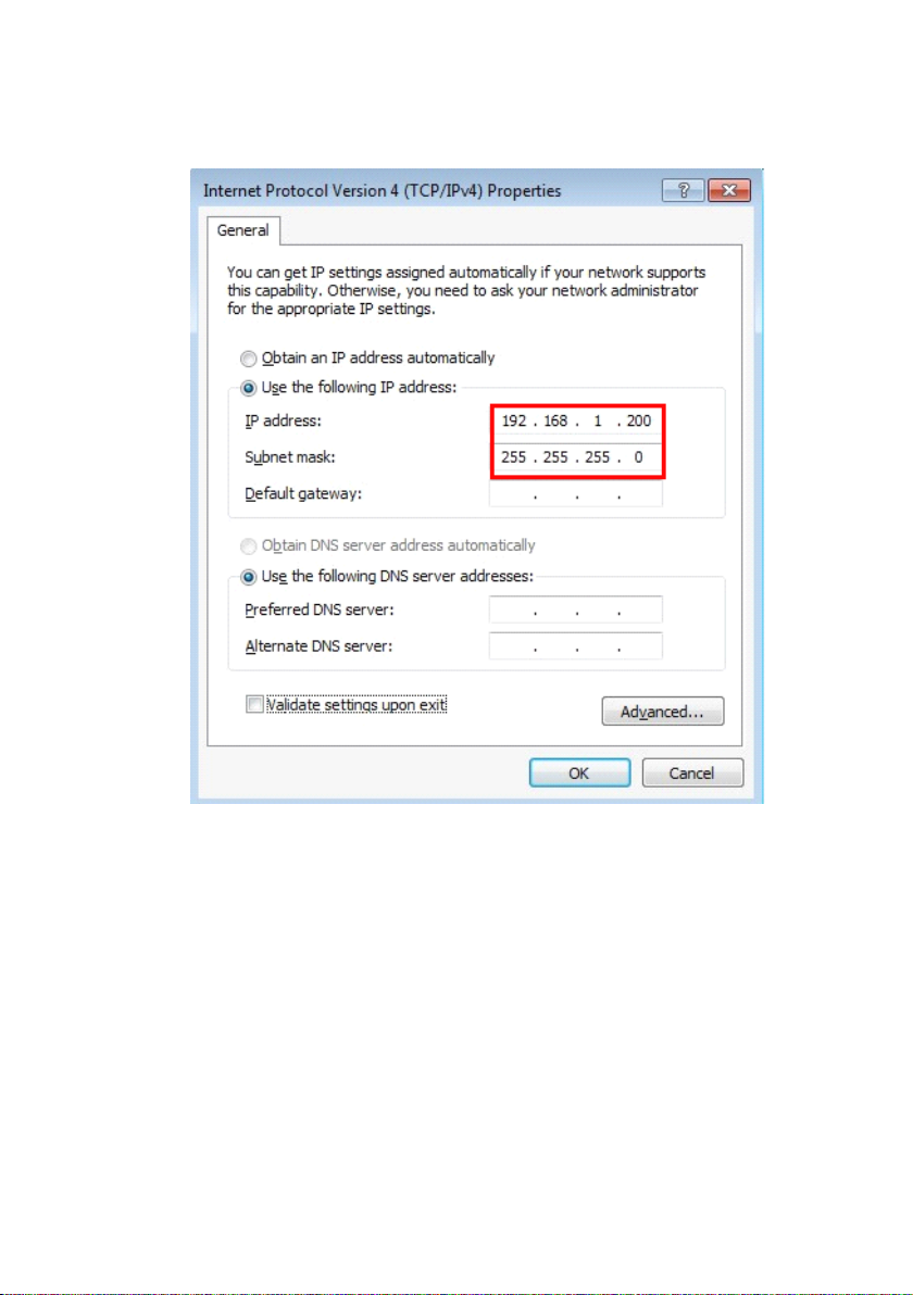
The default IP address of IP device is 192.168.1.199. D efault Subnet Mask is
255.255.255.0
To access the IP device, the IP address of the PC should match the address
below.
IP Address: 192.168.1.xxx
Subnet Mask: 255.255.255.0
NOTE: xxx should be a number from 1 to 254 except 199, which is used by the IP
device. Please make sure that two equipment s cannot share the same IP address in
the same network . For example, you can set up your PC IP address:
192.168.1. 2 00.
B elow is an example to explain the setting procedure s on Windows 7. If your
computer operation system is Win 7, please refer to OS user-manuals for proper
setting up.
device
IP device
device
’
s
IP
’
’
s
s IP
IP address
address
address
address
You
- 7 -
Page 8
STEP1
STEP1
�
�
STEP1
STEP1
�
�
Start up your computer.
STEP2
STEP2
�
�
STEP2
STEP2
�
�
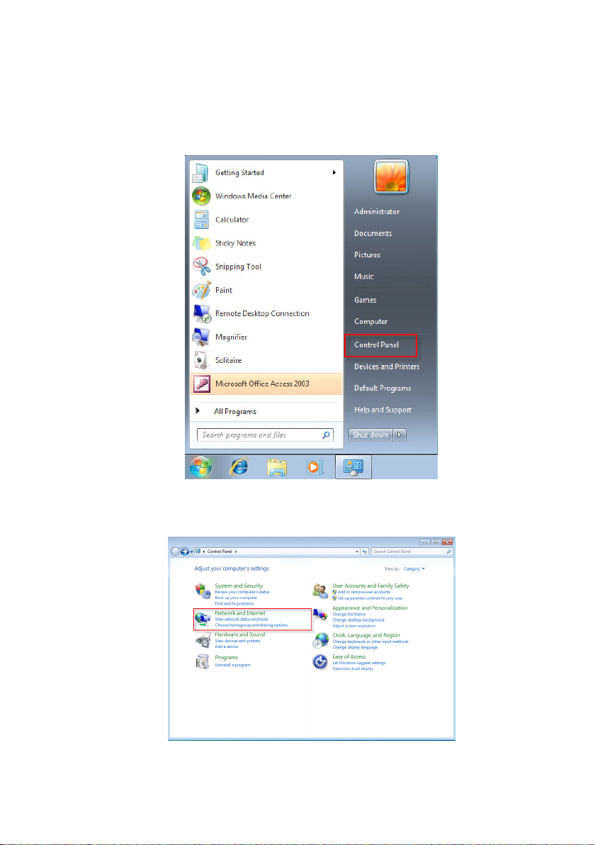
Click the [Start] and select the “ Control Panel ”
STEP3
STEP3
�
�
STEP3
STEP3
�
�
Select the “ Network and Internet connections ” .
- 8 -
Page 9
STEP4
STEP4
�
�
STEP4
STEP4
�
�
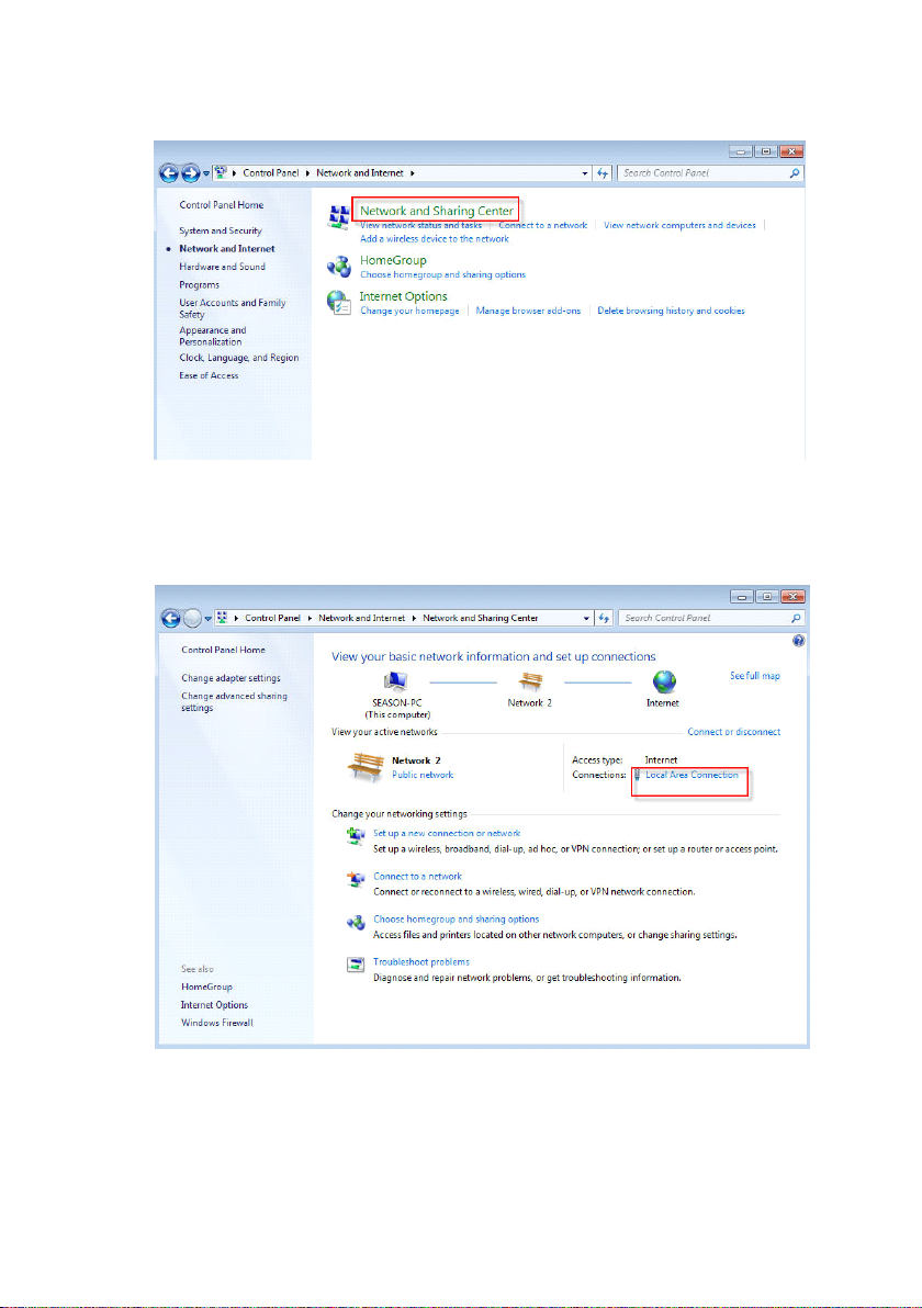
Select the “ Network and Sharing Center ”
�
STEP5
�
STEP5
�
� STEP5
STEP5
Select the “ Local Area Connection ”
.
- 9 -
Page 10
STEP6
STEP6
�
�
STEP6
STEP6
�
�
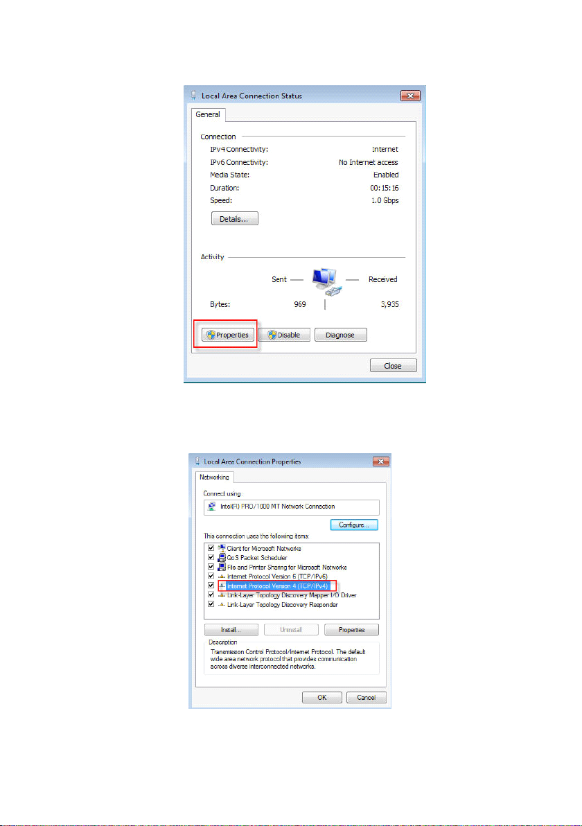
Click the “ Properties ”
STEP7
STEP7
�
�
STEP7
STEP7
�
�
Select the “ Internet Protocol V ersion 4 (TCP/IPv4) ”
- 10 -
Page 11
STEP8
STEP8
�
�
STEP8
STEP8
�
�
Select the “ Use the following IP address ” , enter the IP a ddress and subnet
mask. For example, you can set up your PC IP address: 192.168.1. 2 00
�
STEP9
�
STEP9
�
� STEP9
STEP9
Click the [OK] and close all the dialog windows one by one.
- 11 -
Page 12
1.3
.
Configuring
1.3
.
Configuring
1.3
1.3 .
. Configuring
Configuring the
Once all preparation s of PC ha ve been done, you can login the IP device
through Internet Explorer Browser 6.0 or above.
Follow the procedures below to configure the IP device.
STEP1
STEP1
�
�
STEP1
STEP1
�
�
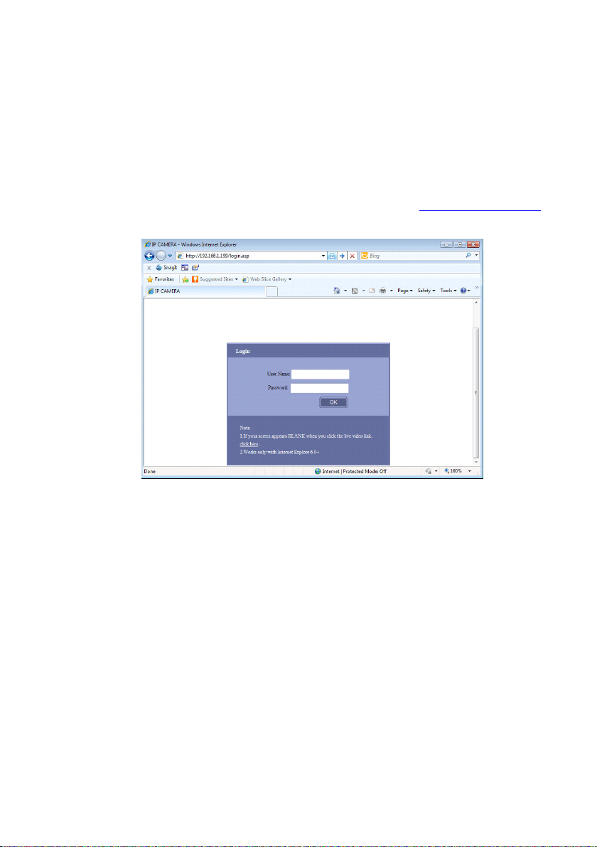
Enter the default IP address of the IP device on Browser : http://192.168.1.199
the
the
the IP
IP
IP
IP D
D
evice
D
evice
D evice
evice
STEP2
STEP2
�
�
STEP2
STEP2
�
�
Enter User name and Password. ( Default user name is 888888, default
password is 888888), then click “ OK ” .
STEP3
STEP3
�
�
STEP3
STEP3
�
�
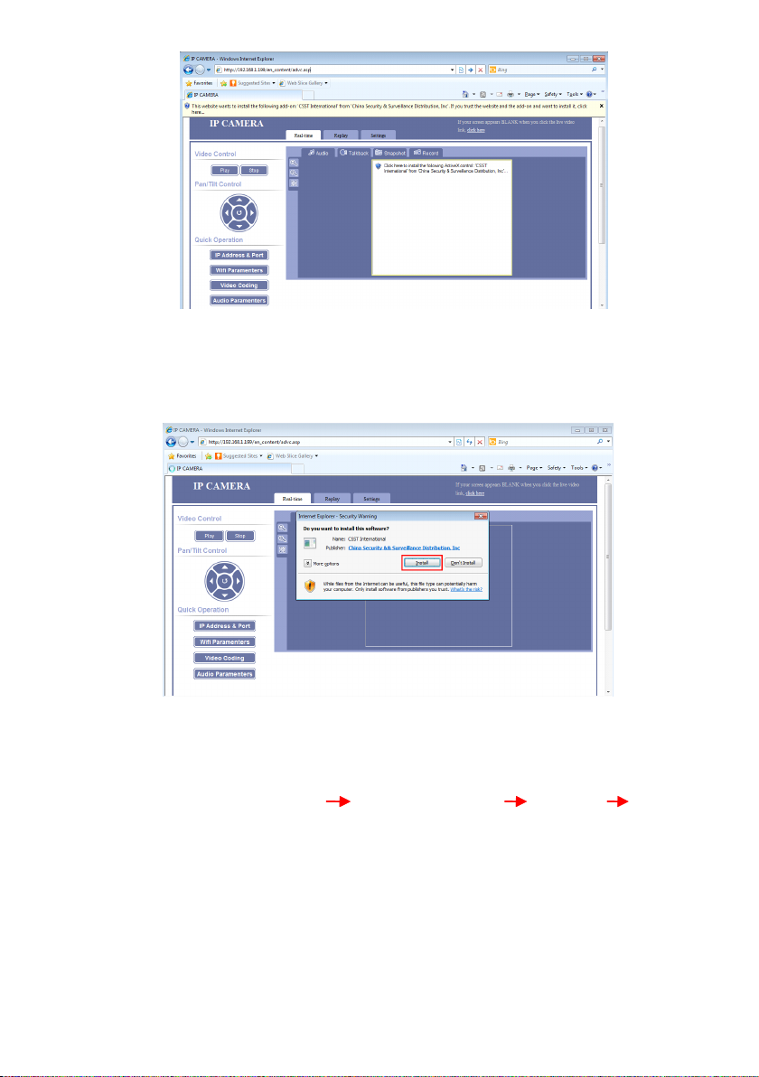
When you login successfully IP device, there is an adding-on Active X control
notices to display on Internet Explorer. All the plug-in in our IP device are safe,
there won ’ t be any bad influence to your computer.
- 12 -
Page 13
STEP4
STEP4
�
�
STEP4
STEP4
�
�
Click the notice, then you will see a window message to ask for your
permission to install the Active X control. Please click “ Install ” to install this
plug-in, otherwise you cannot use our IP device .
N OTE : If you can ’ t see the download ActiveX notification, please follow below
steps:
For IE browser: Click “ Tool ” “ Internet Options ” “ Security ” “ Custom
level ” . Find “ Download signed ActiveX controls ” and check the “ Enable ” radio
button. Click “ OK ” button then restart the IE. You should be able to see the
notification of Download the ActiveX controls.
STEP5
STEP5
�
�
STEP5
STEP5
�
�
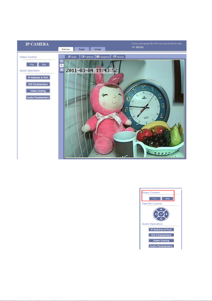
Now, you can view the video after the installation.
- 13 -
Page 14
1.3.1
1.3.1
1.3.1
1.3.1 .
.
Real-time
.
Real-time
. Real-time
Real-time
1.3.1.1.
1.3.1.1.
1.3.1.1.
1.3.1.1. Video
Click “ Play ” button, to view real-time video
Click “ Stop ” button, to stop watching the video.
Video
Control
Video
Control
Video Control
Control
- 14 -
Page 15
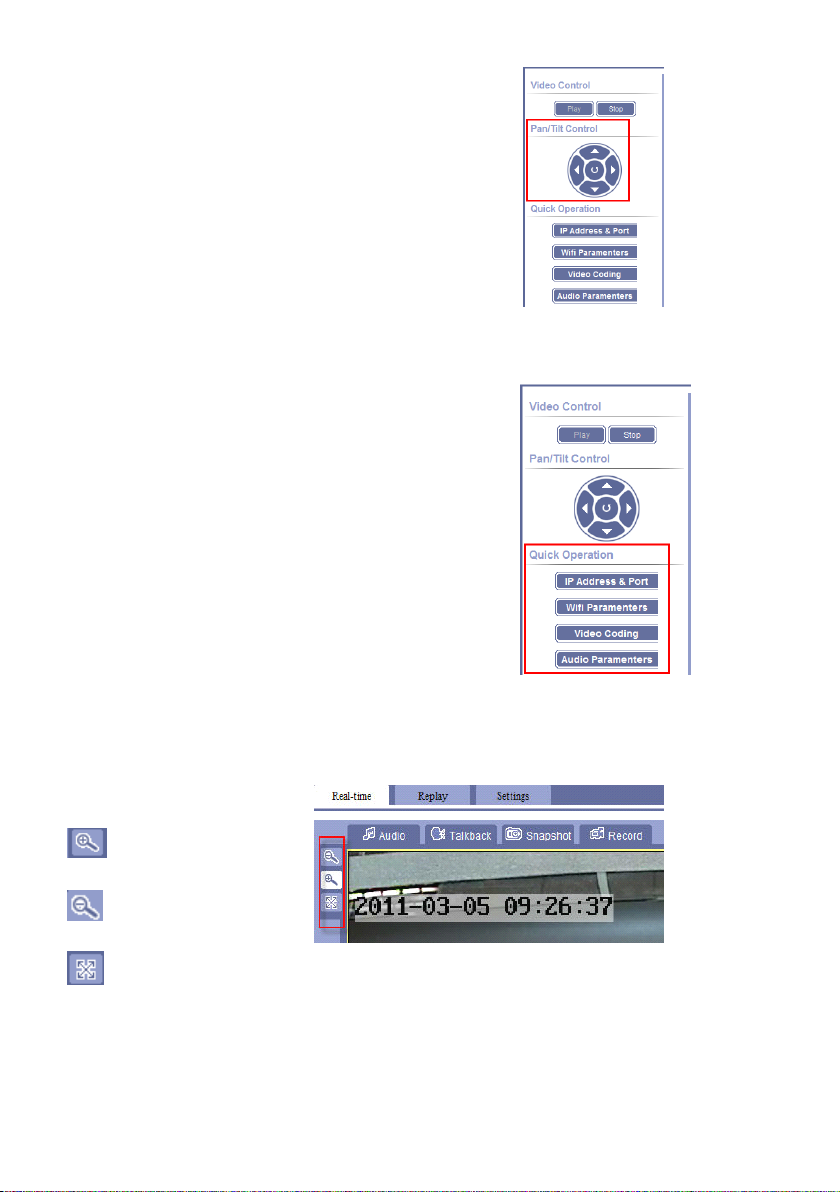
1.3.1.2.
1.3.1.2.
1.3.1.2.
1.3.1.2. Pan/Tilt
Pan/Tilt
Pan/Tilt
Pan/Tilt Operation
Operation
Operation
Operation
Click the right buttons to control
the rotation from Up, Down, Left, Right
and auto rotation.
1.3.1.3.
1.3.1.3.
1.3.1.3.
1.3.1.3. Quick
Quick
Operation
Quick
Operation
Quick Operation
Operation
These three buttons are shortcut s for setting the
IP device, which are direct ed to “ Settings ” interface
of IP device.
1.3.1.4.
1.3.1.4.
1.3.1.4.
1.3.1.4. Size
Size
Size
Size of
of
of
of P
P
review
P
review
P review
review I
I
mage
I
mage
I mage
mage
O riginal display size
H alf of the original
F ull computer screen real-time video ;
when under full screen, right click to turn back to original display size
- 15 -
Page 16
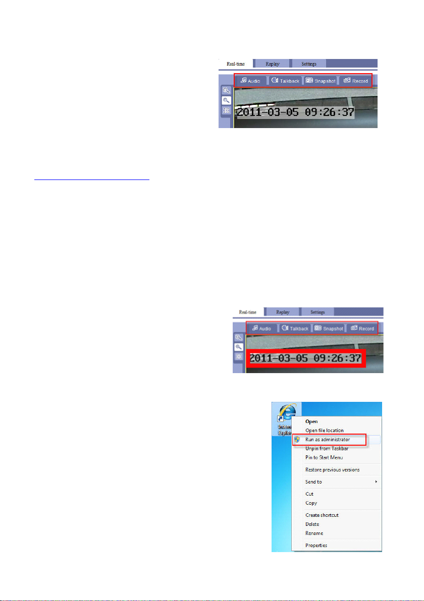
1.3.1.5.
1.3.1.5.
1.3.1.5.
1.3.1.5. Real-time
【 Audio
Real-time
Real-time
Real-time Video
Audio
Audio
Audio 】 Click “ Audio ” button,
Video
Function
Video
Function
Video Function
Function
the button icon will become
orange. Connect a pickup with the
IP device correctly , you will be
able to hear the sound from the IP device via your computer.
Please refer to the following chapter to set the audio parameters:
1.3.3.3.5 Audio Parameters
Talkback
Talkback
【 Talkback
Talkback 】 Click “ Talkback ” button, the button icon will become orange.
Connect a pickup and speaker with the IP device correctly, you will be able to
communicate with the IP device port from your computer .
Snapshot
Snapshot
【 Snapshot
Snapshot 】 Click the “ Snapshot ” per time,
IP device will automatically ca tch a snapshot
with BMP format , and will create a folder by
the name of the current date. The default
snapshot path in the local computer is C:\Temp , the snapshot is named with:
Device name _ 1 _ time. For example: video server_1_ 09 _ 26 _ 3 7 .
NOTE: I f the computer system isVista or W in7 ,
you might fail the capture when c lick ing “ snapshot ” ,
thus, p lease close the browser , right-click the browser
icon , click "Run as administrator" , use administrator
privilege to operate can solve this problem.
- 16 -
Page 17

Record
Record
【 Record
Record 】 Click “ Record ” button, the button icon
will become orange , recording starts. Click the
“ Record ” button to stop recording, the icon turns
back to be white. T he IP device will create
automatically a folder named by the current
recording date , and save the recorded file in
the format of *.mp4.in Disk D. The recorded
file is named with : Device name _ 1 _ time. For example: D:\20110305\video
server_1_ 092637 . mp4 ” .
Please use the “ RealMp4Player ” to play the video recording directly, please
install the player in the attached CD. Or you can replay the recording on the IE
browser in the “ Replay ” interface, please refer to the following chapter for this
operation:
1.3.2 Replay
If RAM of Disk D is full, or the disk has insufficient RAM , the earliest
recorded files will be covered automatically.
NOTE: I f the computer system isVista or W in7 , you might fail the recording when
c lick ing “ Record ” . Thus, p lease close the browser , right-click the browser icon ,
click "Run as administrator" , use administrator privilege to operate can solve this
problem .
- 17 -
Page 18
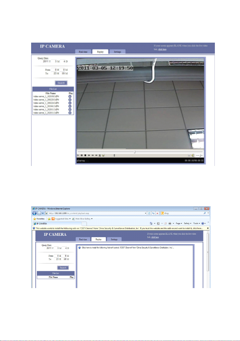
1.3.2
1.3.2
1.3.2
1.3.2 .
an adding-on Active X control notices to display on Internet Explorer. Please click
“ Install ” to install this plug-in, otherwise you cannot view the replay .
.
Replay
.
Replay
. Replay
Replay
This interface is to replay the video.
Click “ Replay ” to enter. When you r first time to enter this interface, there is
- 18 -
Page 19
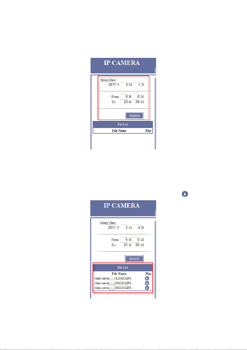
1.3.2.1.
1.3.2.1.
1.3.2.1.
1.3.2.1. Query
Query
Query
Query Date
Date
Date
Date
Select the recording time to replay, click “ Search ” , there will display the file
list in the segment time under the “ File List ” .
1.3.2.2.
1.3.2.2.
1.3.2.2.
1.3.2.2. File
File
File
File L
L
L
L ist
ist
ist
ist
Choose the one you want to replay and click matching icon to playback .
- 19 -
Page 20

1.3.2.3.
1.3.2.3.
1.3.2.3.
1.3.2.3. Play
Play
Play
Play Toolbar
Toolbar
Toolbar
Toolbar
Progress
Progress
【 Progress
Progress bar
bar
bar
bar 】 Click in the progress bar to show the current broadcast ing
schedule, and adjust the broadcasting pace.
P lay the recording .
S uspended play.
Stop play.
Per click “ Step ” , the playback will play only a frame recording. For
example, one second NTSC recording is composed by 30 frames pictures,
then you need to click ” Step ” 30 times to jump to next second.
T o make playback speeds faster.
To make playback speeds slower .
Image sharp pen, to make image relief, value from -1 to 9, -1 is disable, 9 is
the sharpest value.
This is used to cut video clips. First , drag the cursor of the progress bar to
the point, where you want to start the clips, click , the video plays again,
until to the point where you want to stop, click to save this clips.
Save the video clip file.
During playing, click to overturn 180 ° of the video.
Full screen . If it was in pause stat us , it won ’ t work.
Sound control to be soundness
Drag the cursor to adjust the volume.
- 20 -
Page 21
1.3.3
1.3.3
1.3.3
1.3.3 .
1.3.3.1
1.3.3.1
1.3.3.1
1.3.3.1 .
.
Settings
.
Settings
. Settings
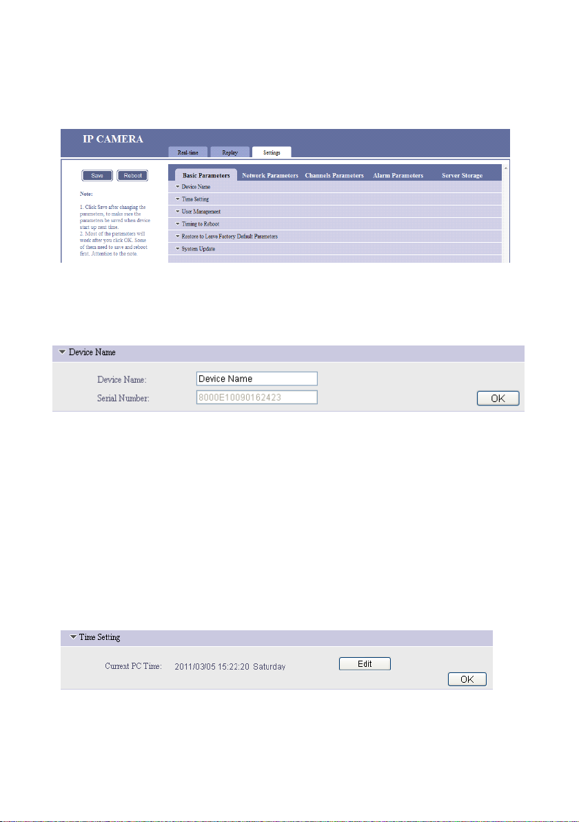
Settings
.
Basic
.
. Basic
Parameters
Basic
Parameters
Basic Parameters
Parameters
1.3.3.1.1.
1.3.3.1.1.
1.3.3.1.1.
1.3.3.1.1. Device
Device
Device
【 Device
Device Name
modify the name. Device name usually display s in the recording files name and
snapshot file name , to distinguish other video s . The device name won ’ t display in
the “ Real – time ” windows .
Serial
Serial
【 Serial
Serial Number
1.3.3.1.2.
1.3.3.1.2.
1.3.3.1.2.
1.3.3.1.2. Time
Device
Device
Device Name
Name
Name
Name 】 Input the name of the device, then click OK to save .
Number
Number
Number 】 S erial number of current IP device , which cannot be changed.
Time
Time
Time Setting
Name
Name
Name
Setting
Setting
Setting
You
can
This function is used to change the time of the IP device. Please refer to the
following steps to modify the time
- 21 -
Page 22
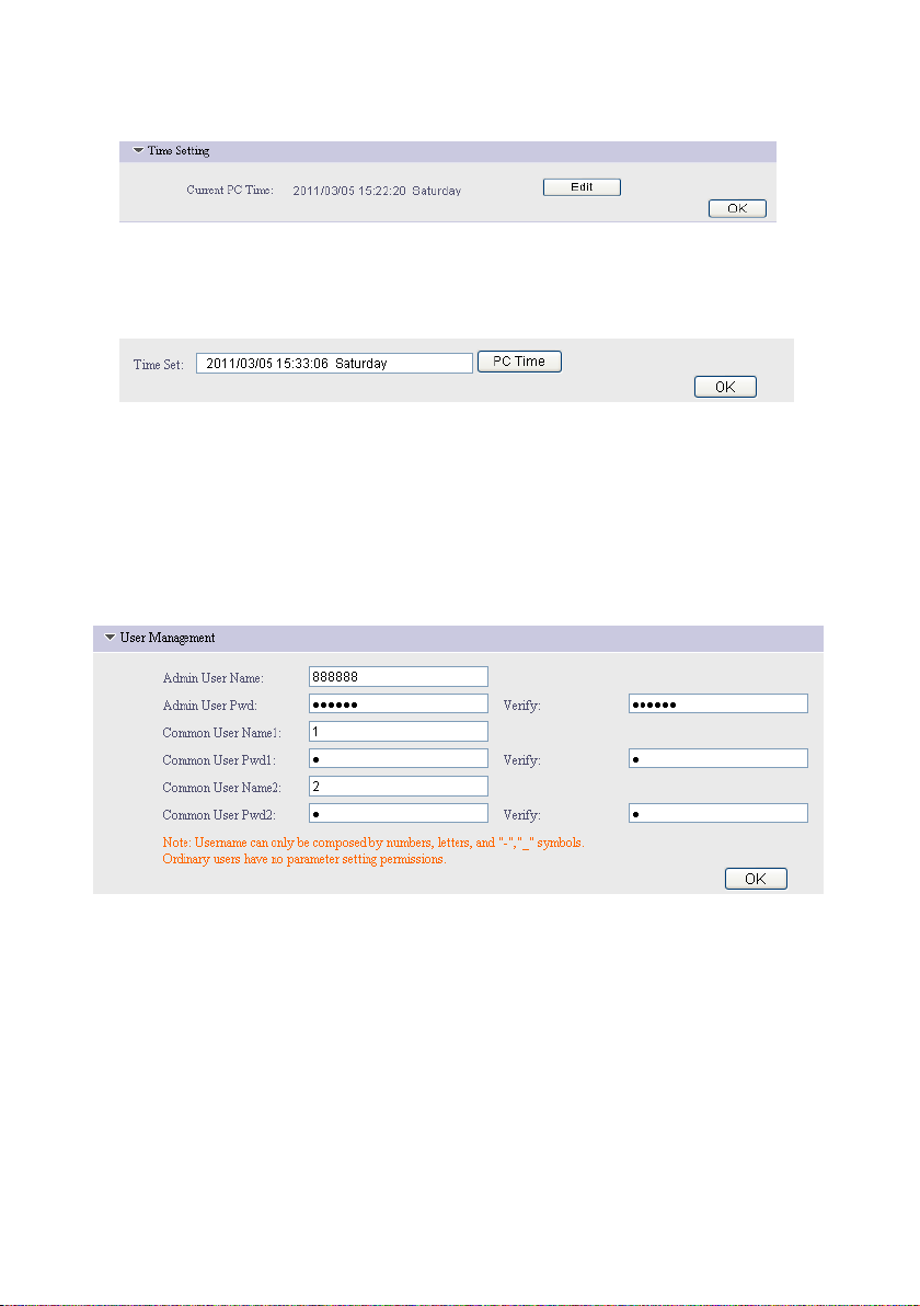
STEP1
STEP1
�
�
STEP1
STEP1
�
�
Click “ Edit ” to modify the time,
STEP2
STEP2
�
�
STEP2
STEP2
�
�
Click “ OK ” to finish the modification.
If you want to have the IP device time the same with the PC time. Please
click the “ PC Time ” and then click “ OK ” to finish.
1.3.3.1.3
1.3.3.1.3
1.3.3.1.3
1.3.3.1.3 .
.
User
Management
.
User
Management
. User
User Management
Management
Default Admin U ser name/ Pw d is: 888888/888888. You can modify them here ,
then click “ OK ” button. This m odif ication requires logging in the webpage again to
browse real-time video.
T he Common User Name 1&2 / Pwd 1&2 is 1/2 separately . Similarly, you can
modify them here, save and re-login in.
NOTE: Please remember all the parameters for the management — Important.
- 22 -
Page 23

1.3.3.1.4
1.3.3.1.4
1.3.3.1.4
1.3.3.1.4 .
.
Time
.
Time
. Time
Time to
to
Reboot
to
Reboot
to Reboot
Reboot
This function is used for rebooting the IP device as long as the power is on.
Keep the “ Timing to Reboot ” “ On ” status, set the “ Reboot Time ” , for
example, set “ 1H5M ” , that is to say, the IP device will reboot on 01:05 every day
as long as the power is on.
1.3.3.1.5
1.3.3.1.5
1.3.3.1.5
1.3.3.1.5 .
.
Restore
.
Restore
. Restore
Restore to
to
L
eave
F
eave
eave F
actory
F
actory
F actory
actory D
to
L
to L
L eave
D
efault
D
efault
D efault
efault P
P
arameters
P
arameters
P arameters
arameters
Click “ Restore ” button and reboot the IP device , all the parameters will be
back to the factory default parameters, except for the device name and IP address &
port.
If you want to make hardware reset, please refer to: 5.1 Hardware Reset
- 23 -
Page 24

1.3.3.1.6
1.3.3.1.6
1.3.3.1.6
1.3.3.1.6 .
.
System
.
System
. System
System Update
Update
Update
Update
This is used for system upgrade. C lick “ Browse …” to choose upgrade files of
“ *. i tm ” format , and then click “ OK ” , until the web page display s “ The program has
been updated successfully, please login again ” , the device will reboot
automatically.
Upgrade file s are provided from your supplier. This is very important and
pivotal, we don't recommend the system upgrade unless you have got the particular
guide from your supplier.
1.3.3.2
1.3.3.2
1.3.3.2
1.3.3.2 .
.
Network
.
Network
. Network
Network P
P
arameters
P
arameters
P arameters
arameters
- 24 -
Page 25

1.3.3.2.1
1.3.3.2.1
1.3.3.2.1
1.3.3.2.1 .
.
.
. IP
IP
IP
IP A
A
ddress
A
ddress
A ddress
ddress &
&
P
ort
&
P
ort
& P
P ort
ort
To access the IP device via W AN, you must map the ports first, please refer to:
5.2 Mapping & Access IP Device via WAN
Connection
Connection
【 Connection
Connection type
Static IP Address, this method is highly recommended.
IP
Address
IP
Address
IP
IP Address
Address Based on network environment to fill out your own IP address or
type
type
type 】
Static IP A ddress, PPPOE, DHCP optional.
keep the default( Default IP address cannot be used with two and more IP
devices on LAN),
Gateway
Gateway
Gateway
Gateway B ased on network environment / IP address to fill out.
Subnet
Subnet
Subnet
Subnet Mask
DNS
DNS
DNS
DNS Keep the same with your route’s DNS. This item related to the
Mask
Mask
Mask B ased on network environment to fill out , or keep the default.
application of DDNS (Dynamic Domain Name Server) and Email Alarm.
PPPOE
Please contact y ou r network operators, to provide the “ PPPOE User Name ”
and “ PPPOE Password" ”
- 25 -
Page 26

DHCP
The following parameters please keep the default or follow our instruction.
WEB
Port
WEB
【 WEB
Port
WEB Port
Port 】 D efault is 80. If you change into another port, you need to add th is
port behind IP address when visit the IP device via IE . For example, IP device is
192.168.1.199, web port is 81, and then the login IP address is
http://192.168.1.199:81 . If you want to visit from WAN (Wide Area Network) via
IE , you must map the WEB port on your router equipment.
Date
Transfer
Date
【 Date
Transfer
Date Transfer
Transfer Port
Port
Port
Port 】 D efault is 3000.
NOTE: in system backstage, there hide a date control port , default is 3001. Date
control port = date transfer port + 1. If you change the date transfer port into
4000, the system will automatically change date control port is 4001.
When visiting the IP device via WAN, you have to map the date transfer port
and date control port on the router. Because you have to visit the IP device on
WAN through date control port and date transfer port .
Alarm
Alarm
【 Alarm
Alarm Host
Alarm
Alarm
【 Alarm
Alarm Host
Remote
Remote
【 Remote
Remote Host
Host
Address
Host
Address
Host Address
Address 】 Alarm Host Address , keep the default.
Host
Port
Host
Port
Host Port
Port 】 Alarm Host Port , keep the default.
Host
Address
Host
Address
Host Address
Address 】 Remote Host Address. This function is used IP device
initiative send date to remote host. Keep the default.
Remote
Remote
【 Remote
Remote Host
Host
Port
Host
Port
Host Port
Port 】 Remote Host Port. The default
is 3004. Keep the default.
Multicast
Multicast
【 Multicast
Multicast Address
Multicast
Multicast
【 Multicast
Multicast Port
Address
Address
Address 】 Keep the default.
Port
Port
Port 】 Keep the default.
- 26 -
Page 27

NOTE: when you change the above parameters, you must click on the upper left
corner “ Save ” and “ Reboot ” to take effect.
1.3.3.2.2
1.3.3.2.2
1.3.3.2.2
1.3.3.2.2 .
.
WIFI
.
. WIFI
Parameters
WIFI
Parameters
WIFI Parameters
Parameters
You need a wireless router of 802.11b/g before you use the WiFi function,
please setup the SSID name and Encryption of Wireless Network in your wireless
router.
Wireless
Wireless
【 Wireless
Wireless Network
Network
Network
Network 】 Click “ Refresh ” to find the SSID name and Encryption you
have set in the “ Wireless Network ” . Double-click the SSID name and Encryption,
the SSID will be auto input in the “ Currently Wireless Network ” , please input the
password.
IP
Address
IP
Address
【 IP
IP Address
Address Configuration
Configuration
Configuration
Configuration 】
- 27 -
Page 28

There are three methods to enable WIFI function: Static IP
Address/PPPOE/DHCP.
Static IP Address
PPPOE
If you choose to PPPOE, please contact y ou r network operators, to provide
the “ PPPOE User Name ” and “ PPPOE Password" ”
DHCP
The following parameters will keep the same under these three methods.
IP
Address
IP
Address
IP
IP Address
Address Based on network environment to fill out your own IP device
address
Subnet
Subnet
Subnet
Subnet Mask
Gateway
Gateway
Gateway
Gateway Keep this item the same with the IP address of your wireless router.
DNS
DNS
DNS
DNS Keep the same with your route’s DNS. This item related to the
Mask
Mask
Mask B ased on network environment to fill out
application of DDNS (Dynamic Domain Name Server) and Email Alarm.
NOTE: When connect the WAN via WIFI, Please enable the “ WIFI Gateway as
Default Gateway ” , and choose WIFI specification: 802.11b & 802.11g.
For detail Wireless setting, please refer to: 5.3 Wireless Settings
- 28 -
Page 29

1.3.3.2.
1.3.3.2.
1.3.3.2.
1.3.3.2. 3.
3.
DDNS
3.
DDNS
3. DDNS
DDNS
DDNS (Dynamic DNS) is simply a way of using a static hostname to connect
to a dynamic IP address. When connected to your
ISP,
you are assigned a
temporary IP address. DDNS services keep track of your IP address and route your
Domain name to that address when you wish to connect to the IP device from a
remote location.
How to add DDNS ( take Dyndns for example )
STEP1
STEP1
STEP1
STEP1 Select “ Start DDNS ” 。
STEP2
STEP2
STEP2
STEP2 Choose “ DDNS Supplier ” is to be “ Support Dyndns ”
STEP3
STEP3
STEP3
STEP3 Fill in Domain Name , Domain User Name and DDNS password by
your DDNS service provider when you registered.
STEP4
STEP4
STEP4
STEP4 DDNS Server Address , DDNS Server Port , Update Interval. Use the
system default parameters.
STEP5
STEP5
STEP5
STEP5 WEB M apping Port must keep the same as WEB Port of “ IP
Address & Port ” .
- 29 -
Page 30

1.3.3.2.
1.3.3.2.
1.3.3.2.
1.3.3.2. 4.
4.
FTP
4.
4. FTP
Parameters
FTP
Parameters
FTP Parameters
Parameters
This function is used for uploading the files to FTP server.
You
must have an
FTP server, if you don't have, you cannot use this function.
FTP
User
FTP
【 FTP
FTP User
Name
User
Name
User Name
Name 】 D efault is 888888, please change into your own FTP server
User Name.
FTP
Password
FTP
【 FTP
Password
FTP Password
Password 】 D efault is 888888, please change into your own FTP server
Password.
FTP
Host
FTP
【 FTP
FTP Host
IP
Host
IP
Host IP
IP 】 D efault is 192.168.1.40, please change into your own FTP server
landing IP address.
FTP
Host
FTP
【 FTP
FTP Host
Post
Host
Post
Host Post
Post 】 D efault is 21, please change into your own FTP server Host
Post.
NOTE : If you modify FTP parameters, need to Save and Reboot the IP device.
- 30 -
Page 31

1.3.3.2.
1.3.3.2.
1.3.3.2.
1.3.3.2. 5.
5.
5.
5. FTP
FTP
FTP
FTP S
S
cheduled
S
cheduled
S cheduled
cheduled R
R
ecord
R
ecord
R ecord
ecord
This function is used for automatically uploading the recording to the FTP
server according to the schedule. Please set the schedule first.
How to upload recording to FTP Server:
STEP1
STEP1
STEP1
STEP1 Built a FTP server , set up the user name, password, FTP server IP
and port.
STEP2
STEP2
STEP2
STEP2 Fill in your FTP p arameters in the IP device. Click OK.
STEP3
STEP3
STEP3
STEP3 Setting FTP scheduled record ing . For example: set to upload
recording file s of IP device on Monday 0:10 am , and stop upload on 23: 59 pm .
- 31 -
Page 32

STEP4
STEP4
STEP4
STEP4 You can see the similar video on the FTP server.
- 32 -
Page 33

1.3.3.2.
1.3.3.2.
1.3.3.2.
1.3.3.2. 6.
6.
UPNP
6.
UPNP
6. UPNP
UPNP
UP N P is a quick way to discover the IP device on the network. Via UPNP
function, the above ports could be mapped automatically in the router.
External IP Address: W AN IP address of the router.
How to use UPNP function :
STEP1
STEP1
STEP1
STEP1 Please enable the UPNP function both on the IP device and router.
(Please note that not all routers support this function. Refer to your router manual
for further details ). The IP device will map automatically.
- 33 -
Page 34

STEP
2
STEP
2
STEP
STEP 2
2 If “ State ” display “ Mapped ” , means UPNP setting s is success ful ,
please refer to the above picture . Then , please follow the below procedures to
access the IP device via WAN :
http://External IP Address:W eb Port . If External IP is : 119.145.0.165 and
Web Port is 80.The address is: http://119.145.0.165:80
N OTE : The router must support UPNP and keep “ On ” state. If the UPNP of the
router and IP device both are “ ON ” , but the state of the port s above is still
“ Unmapped ” , please check the router settings if the port have been used already . If
there are more than one device connect ed in the same gateway, the port of each
device should be different to avoid the port conflict.
1.3.3.2.
1.3.3.2.
1.3.3.2.
1.3.3.2. 7.
7.
Streaming
7.
Streaming
7. Streaming
Streaming Protocol
Protocol
Protocol
Protocol
These two streaming protocols are for higher requirement users and
broadcasting clients. Please refer to the A ppendix : 5.1 How to Use the Streaming
Protocol
- 34 -
Page 35

1.3.3.2.
1.3.3.2.
1.3.3.2.
1.3.3.2. 8.
8.
8.
8. P2P
P2P
P2P
P2P
This function is very important for mobile monitoring. For details of mobile
monitor, please refer to the “ Mobile Monitor Operation Manual ” in the CD:
Enable
Enable
【 Enable
Enable P2P
Message
Message
【 Message
Message port
P2P
P2P
P2P 】 E nabled or disabled P2P 。
port
port
port 】 The default is 4602. After you setting the UPNP, this port will be
automatically mapp ed out.
User
name
User
【 User
【 Password
【 Network
name
User name
name 】 The default is admin
Password
Password
Password 】 The default is admin
Network
Network
Network Transfer
Transfer
Transfer
Transfer Stream
Stream
Stream
Stream 】 Main Stream, sub-stream and 2sub Stream optional.
Strongly suggest choos ing 2sub stream. About 2sub stream settings, please refer to :
1.3.3.3.2 Video Coding
- 35 -
Page 36

1.3.3.3
1.3.3.3
1.3.3.3
1.3.3.3 .
.
Channels
.
Channels
. Channels
Channels Parameters
Parameters
Parameters
Parameters
1.3.3.3.1
1.3.3.3.1
1.3.3.3.1
1.3.3.3.1 .
【 Channel
.
Character
.
Character
. Character
Character S
Channel
Channel
Channel Name
Name
Name
Name 】 To distinguish different equipment. But it won't show in
S
uperposition
S
uperposition
S uperposition
uperposition
preview screen. Keep the default.
Time
Type
Time
【 Time
【 Frame
Type
Time Type
Type 】 Choose the time type from the four formats.
Frame
Frame
Frame Rate
Rate
Rate
Rate 】 Including “ Not indicating ” and “ indicating ” . Choose “ indicating ” ,
the real-time screen will display the B it R ate, i f choose “ not indicating ” , will not
display the Bit R ate.
Character1
Character1
【 Character1
Character1 】 , 【 Character2
Character2
Character2
Character2 】 Input the characters to be displayed in video
superposition. You type what you want to display on the real-time screen.
Location
Location
【 Location
Location 】 To adjust character position. Location of OSD superposition: in
NTSC system, X is 0-672 and Y is 0-448.
- 36 -
Page 37

1.3.3.3.2
1.3.3.3.2
1.3.3.3.2
1.3.3.3.2 .
.
Video
.
. Video
Coding
Video
Coding
Video Coding
Coding
Network
Network
【 Network
Network Transfer
Transfer
Transfer
Transfer Stream
Stream
Stream
Stream 】 This is a main stream of IP
d evice. This stream is used for IE View.
Resolution —— Five image resolutions available:
704X576 (D1), 704 x 288(2CIF), 352 x 288(CIF),
176 x 144(QCIF) , 320 x 240(QVGA)
Bite Rate Type —— “ Constant ” and “ Variable ” . If
you c hoose “ Constant ” , it ensures transmission fluency.
If you choose “ Variable ” , it ensures the steady image
quality. Constant is recommended.
MAX. Bite Rate —— the range is 32 to 4000 optional.
The higher the Bite Rate is, the clearer the image is. M ore bandwidth is
needed for higher Bite Rate.
Quality Upper Limit —— the highest quality is 2. Keep the default.
Quality Lower Limit —— the Lowest quality is 31. Keep the default.
Frame Rate —— the 2-30 frames can be filled. The higher the Frame Rate is,
the clearer the image is. M ore bandwidth is needed for higher Frame Rate.
Stream Type ——“ Video & Audio ” or “ Video only ” optional. If choose
“ Video only ” , you cannot hear any sound on Talkback interface . Also, the
recording won't have voice.
- 37 -
Page 38

Key Frame Interval —— keep the default.
Compression —— H.264 and MJPEG optional.
NOTE: Save and reboot is a must after change.
Server-end
Server-end
【 Server-end
Server-end Storage
Mobile
Mobile
【 Mobile
Mobile Watching
Storage
Storage
Storage Stream
Watching
Watching
Watching Stream
Stream
Stream
Stream 】 This is used for SD card storage stream setting.
Stream
Stream
Stream 】 This is the mobile phone transmission streaming.
Please keep the default.
1.3.3.3.3
1.3.3.3.3
1.3.3.3.3
1.3.3.3.3 .
【 Brightness
【 Contrast
【 Saturation
【 Hue
【 Horizontal
.
Adjust
.
Adjust
. Adjust
Adjust Color
Brightness
Brightness
Brightness 】 Brightness adjustment.
Contrast
Contrast
Contrast 】 Contrast adjustment.
Saturation
Saturation
Saturation 】 Saturation adjustment.
Hue
Hue
Hue 】 Chromaticity adjustment.
Horizontal
Horizontal
Horizontal Offset
Color
Color
Color
Offset
Offset
Offset 】 Horizontal adjustment for the r eal-time image position in the
window. It could be moved from side to side. Please keep the default.
- 38 -
Page 39

1.3.3.3.4
1.3.3.3.4
1.3.3.3.4
1.3.3.3.4 .
.
Area
.
Area
. Area
Area Shield
Shield
Shield
Shield
This function is used for privacy shield protection.
Area
Area
【 Area
Area 】 The default Area 1 icon is green, but without any privacy shield area
You
can set total 4 areas.
setting . Please e nable the “ Area Shield On- off ” , Left click in the video on the left
side, hold on and move, release the mouse to finish the shield for Area 1. The
same operation for Area 2 and the others: setting the shield area, then click the
Area 2. Click OK to save.
To clear the shield, please choose the Area, and click “ Clear ” , then click “ OK ”
the shield will be cancelled. Or disable the “ Area Shield On- off ” to cancel all the
shields.
Clear
Clear
Clear
Clear Clear privacy area.
Area
Shield
Area
Area
Area Shield
1.3.3.3.5
1.3.3.3.5
1.3.3.3.5
1.3.3.3.5 .
.
Audio
.
Audio
. Audio
Audio Parameters
On-off
Shield
On-off
Shield On-off
On-off Enable or disable privacy area .
Parameters
Parameters
Parameters
This is used for adjust ing the IP device input volume. The range is 0-100. The
higher the volume is, the higher the input sound is.
- 39 -
Page 40

1.3.3.4
1.3.3.4
1.3.3.4
1.3.3.4 .
.
Alarm
.
Alarm
. Alarm
Alarm Parameters
Parameters
Parameters
Parameters
1.3.3.4.1
1.3.3.4.1
1.3.3.4.1
1.3.3.4.1 .
.
Sensor
.
Sensor
. Sensor
Sensor Detection
Detection
Detection
Detection Schedule
Schedule
Schedule
Schedule Settings
Settings
Settings
Settings
This function is used for setting the sensor detection Schedule . To use this
function, please connect alarm sensor to the IP device. I f you want to upload sensor
detection recording file of IP device on Monday 0:10 AM, and stop upload on 23:
59 PM. You can set according to above.
- 40 -
Page 41

1.3.3.4.
1.3.3.4.
1.3.3.4.
1.3.3.4. 2.
2.
Motion
2.
Motion
2. Motion
Motion Detection
Detection
Detection
Detection Area
Area
Settings
Area
Settings
Area Settings
Settings
Sensibility
Sensibility
【 Sensibility
Sensibility Adjusting
Adjusting
Adjusting
Adjusting 】 Sensitivity adjustment. 1 to 99 Adjustable. Suggest to use
the default parameters, if sensitivity adjustment is too higher, which can cause
unnecessary alarm.
Left click the real-time area and move to choose the motion detection area.
Select
full
Select
Select
Select full
Clear
Clear
Clear
Clear All
Screen
full
Screen
full Screen
Screen C hoose full Screen for motion detection area , click OK.
All
All
All Clear all the motion detecting area . Click OK.
- 41 -
Page 42

1.3.3.4.
1.3.3.4.
1.3.3.4.
1.3.3.4. 3.
3.
Motion
3.
Motion
3. Motion
Motion Detection
Detection
Detection
Detection Schedule
Schedule
Schedule
Schedule Settings
Settings
Settings
Settings
This function is used for set ting the motion detection Schedule . To use this
function, please connect an alarm sensor to the IP device. I f you want to upload
motion detection recording file of IP device on Monday 0:10 AM, and stop upload
on 23: 59 PM. You can set according to above.
Start
Sensor
Start
【 Start
【 Start
Sensor
Start Sensor
Sensor Detection
Start
Server-end
Start
Server-end
Start Server-end
Server-end Recording
Detection
Detection
Detection 】 Enable or disable sensor detecting.
Recording
Recording
Recording While
While
Alarming
While
Alarming
While Alarming
Alarming 】 Store the alarming recording in
server-end SD card
Start
Server-end
Start
【 Start
【 Upload
Server-end
Start Server-end
Server-end Snapshot
Upload
Upload
Upload The
The
The
The Alarm
Snapshot
Snapshot
Snapshot 】 Store the alarming snapshot in server-end SD card
Alarm
Alarm
Alarm Recording
The FTP server.
Upload
Upload
【 Upload
Upload The
The
Alarm
The
Alarm
The Alarm
Alarm Snapshot
Snapshot
Snapshot
Snapshot to
picture to The FTP server.
Triggering
Triggering
【 Triggering
Triggering Alarm
Alarm
Alarm
Alarm Output
Output
Output
Output 】 Enable this function to trigger the sensor detection
alarm output
Recording
Recording
Recording to
to
FTP
to
FTP
to FTP
FTP 】 Upload sensor detecting recording to
to
FTP
to
FTP
to FTP
FTP 】 Upload sensor detecting captured
- 42 -
Page 43

1.3.3.4.
1.3.3.4.
1.3.3.4.
1.3.3.4. 4.
4.
4.
4. Camera Been Shaded Alarm Trigger Schedule Settings
When the IP device is shaded, there will alarm in the CMS via this function.
Camera
Camera
【 Camera
Camera Been
Triggering
Triggering
【 Triggering
Triggering Alarm
Sensibility
Sensibility
【 Sensibility
Sensibility 】 】 Sensitivity adjustment. 1 to 5 Adjustable. Suggest to use the
Been
Shaded
Been
Shaded
Been Shaded
Shaded Detection
Alarm
Alarm
Alarm Output
Detection
Detection
Detection 】 Please enable this function before setting.
Output
Output
Output 】 Please enable this function before setting
default parameters, if sensitivity adjustment is too higher, which can cause
unnecessary alarm.
1.3.3.4.
1.3.3.4.
1.3.3.4.
1.3.3.4. 5.
5.
Email
5.
Email
5. Email
Email Alarm
Alarm
Alarm
Alarm Settings
Settings
Settings
Settings
This is an email alarm function . When the motion detection is enabled, IP
device will set an alarm email to receiver’s mail box which you fill in.
NOTE: Your email has to support the SMTP protocol, you ’ d better check with your
email supplier.
- 43 -
Page 44

Se
nd
Email
If
There
Se
nd
Email
【 Se
Se nd
nd Email
Priority
Priority
【 Priority
Priority 】 Default is 0.
User
User
【 User
User Name
Password
Password
【 Password
Password 】 Password of email box
Mail
Mail
【 Mail
Mail Server
Mail
Mail
【 Mail
Mail Server
If
Email If
If There
Name
Name
Name 】 User name of email box.
Server
Server
Server IP
Server
Server
Server Port
IP
IP
IP 】 Mail Server IP ( SMTP )
Port
Port
Port 】 SMTP Server Port.
There
There Are
Are
Are
Are Alarm
Alarm
Alarm
Alarm 】 “ On ” and “ Off ” optional
Sender's
Sender's
【 Sender's
Sender's Name
Sender's
Sender's
【 Sender's
Sender's Email
Receiver's
Receiver's
【 Receiver's
Receiver's Name
Receiver's
Receiver's
【 Receiver's
Receiver's Email
Test
Test
【 Test
Test 】 After you fill in all the parameters, please click “ Test ” button to test. If the
Name
Name
Name 】 Sender’s name
Email
Email
Email 】 Sender’s email address
Name
Name
Name 】 Receiver’s name
Email
Email
Email 】
You
can fill in three mail box.
notice “ Successful ” , it means all information are correct and you can use email
alarm function. If the notice is “ Connect mailsever failed ” , please check the
parameters again.
How to set motion detection email alarm function?
STEP1
STEP1
STEP1
STEP1 Please set up motion detection, please refer to : 1.3.3.4.1 Motion
Detection Area Settings
STEP2
STEP2
STEP2
STEP2 Please set correct IP address, especially to fill in correctly DNS
according to your IP device setting and network environment .
STEP3
STEP3
STEP3
STEP3 Please make sure all information of email alarm setting is correct.
Here is an example of using Foxmail to explain how to set up.
- 44 -
Page 45

STEP4
STEP4
STEP4
STEP4 Click “ Test ” button to test all parameters. If all are correct, email
alarm will be triggered by motion detection.
N OTE : There is no request for Receiver's Email as long as it is valid. But the
Sender's Email must be able to receive email via software like foxmail or outlook.
The best choice is the tariff email box.
- 45 -
Page 46

1.3.3.5.
1.3.3.5.
1.3.3.5.
1.3.3.5. Server
Server
Server
Server Storage
Storage
Storage
Storage
1.3.3.5.1.
1.3.3.5.1.
1.3.3.5.1.
1.3.3.5.1. Server-end
Server-end
Server-end
Server-end Timing
Timing
Timing
Timing to
to
Record
to
Record
to Record
Record
This IP device supports SD card to store the recording, the max capacity is
32GB.
Here you can set the time of video recorded to the SD card. Please enable the
timing recording first.
1.3.3.5.2.
1.3.3.5.2.
1.3.3.5.2.
1.3.3.5.2. Server-end
Server-end
Server-end
Server-end T
T
iming
T
iming
T iming
iming to
to
S
to
S
to S
S napshot
napshot
napshot
napshot
In this function, you can set the snapshot parameters.
- 46 -
Page 47

Snapshot
Snapshot
【 Snapshot
Snapshot Time
Time
Interval
Time
Interval
Time Interval
Interval 】 Please set the snapshot time interval, from 10-3600
seconds.
Start
Start
【 Start
Start Timing
FTP
FTP
【 FTP
FTP Upload
Timing
Timing
Timing Snapshot
Upload
Upload
Upload after
Snapshot
Snapshot
Snapshot 】 Please choose the time to activate the snapshot
after
after
after Snapshot
1.3.3.2.3 FTP Parameters
Snapshot
Snapshot
Snapshot 】 Please refer to the chapter
1.3.3.5.3.
1.3.3.5.3.
1.3.3.5.3.
1.3.3.5.3. Server-end
You
Snapshot
Snapshot
【 Snapshot
Snapshot Image
Server-end
Server-end
Server-end Snapshot
Snapshot
Snapshot
Snapshot Parameters
Parameters
Parameters
Parameters
could set the image quality and format of the snapshot.
Image
Image
Image Quality
Quality
Quality
Quality 】 From 1-100,the higher the numerical volume is, the
higher the image quality is.
Snapshot
Snapshot
【 Snapshot
Snapshot Image
Image
Image
Image Format
Format
Format
Format 】 Resolution for D1/2CIF/CIF optional:
D1=2 × 2CIF=4 × CIF .
- 47 -
Page 48

1.3.3.5.4
1.3.3.5.4
1.3.3.5.4
1.3.3.5.4 .
.
Server-end
.
Server-end
. Server-end
Server-end Storage
Storage
Storage
Storage Device
Device
Device
Device
Cut off the power, insert the SD card, click “ Format ” , then reboot and login in
the IP device, there will display the info of the SD card in this interface, then you
can use SD card function now.
- 48 -
Page 49

2
.
Specifications
2
.
Specifications
2
2 .
. Specifications
Specifications
Hardware Compression
CPU:
FLASH:
DRAM:
System:
Resolution:
Motion detection:
Watermark video:
Audio Compression Format: G.722
Network Connector Protocol: 10/100MBaseT,RJ-45
Environment Temperature:
Humidity
Power:
White balance:
Iris:
CCD:
Minimum Illumination:
AGC:
IE Browser: Support
H.264
HI3512
8M
32M
Built-in Linux
D1,CIF
Yes
Yes
8kbit/s
HTTP,TCP/IP ,RTSP,UDP ,DNS
-10℃-55
5%-85%RH
DC12V/2A
Auto
Auto
1/3" 48 0TVL SONY CCD
0Lux
+26Db Max
℃
DDNS: Support
Motion detection: Support
Infrared 20m
RTSP Support
WIFI Support
SD card slot Support
- 49 -
Page 50

3
.
Physical
3
.
Physical
3
3 .
. Physical
Physical Description
⑴ Wireless port: Connect wireless antenna
⑵ Power port: Connect 12V power adapter
⑶ RS485: Connect external PTZ device port
⑷ Network port: Connect network cable
⑸ SD card slot: Insert SD card
⑹ Power indicate lamp : Keep red when power on
⑺ Rest: Rest the IP device to be factory default
⑻ Audio out port: Connect speaker
⑼ SW: Emergency switch for upgrade
⑽ Alarm IN: External sensor alarm in; G: ground connection
Alarm OUT: External alarm out; A-Anode, B-cathode
⑾ State indicate lamp : Keep red light flicking when working
⑿ Audio in port: Connect pickup
Description
Description
Description
- 50 -
Page 51

4
.
Frequent
4
.
Frequent
4
4 .
. Frequent
Frequent Asked
4.1
.
Fail
to
A
4.1
.
Fail
4.1
4.1 .
. Fail
Fail to
Possible Cause: The network is disconnected?
Solution: Connect PC to the network to test whether the network access can
work normally. Firstly clear the cable fault and the network fault caused by PC
virus till Ping the network between PCs successfully.
Possible Cause: IP address is occupied by other equipment.
Solution: Disconnect the IP device and network, and then connect the IP
device to the PC solely. Also, reset the IP address according to appropriate
recommended operations.
Possible Cause: IP address is located in different subnets.
Solution: Check the settings of the IP address of IP device, the subnet mask
address and gateway.
to
to A
ccess
A
ccess
A ccess
ccess the
Asked
Asked
Asked Questions
the
IP
the
IP
the IP
IP Device
Questions
Questions
Questions
Device
Device
Device T
T
hrough
T
hrough
T hrough
hrough the
the
the
the B
B
rowser
B
rowser
B rowser
rowser
Possible Cause: Unknown
Solution: Restore to the factory-set default state by pressing the restore button
behind the IP device.
- 51 -
Page 52

4.2
.
Can
Not
P
lay
V
ideo
A
fter
P
4.2
.
Can
Not
P
lay
V
ideo
A
P
P
P ass
A fter
ass
ass
ass ed
fter
fter P
4.2
4.2 .
. Can
Can Not
Not P
P lay
lay V
V ideo
ideo A
Solution: Close all the browser pages; search “ NetViewX Control.cab ” file
under the C:\Windows\Downloaded and delete it. Then connect the IP device
by the browser again, the IP device real-time view will automatically display
after install the plug-in again .
4.3
.
Fail
to
B
4.3
.
Fail
4.3
4.3 .
. Fail
Fail to
Solution: Install the DirecteX8.0 or higher version. Update the IE Explore to 6
and above version s .
4.
4.
C
4.
4.
4. 4.
Possible Cause:
an
4.
C
an
4. C
C an
an Not
rowse
to
B
rowse
to B
B rowse
rowse I
Not
Get
Not
Get
Not Get
Get Data
I
I
I mages
Data
Data
Data P
mages
mages
mages N
rogram
P
rogram
P rogram
rogram U
N
ormally
N
ormally
N ormally
ormally in
ed
T
hrough
ed
T
hrough
ed T
T hrough
hrough S
U
pdating
U
pdating
U pdating
pdating
in
Windows98
in
Windows98
in Windows98
Windows98
S
witch
S
witch
S witch
witch
The address is written wrong?
The bindings of port and physical address are done or not?
When configuring the firewall rule, whether take IP device into account.
Solution:
Before searching the network fault, please make sure to use the ping
command in the command mode to connect the IP address.
message returned from ping is a very important step. If no message is
returned, it indicates that some faults must exist in the network.
If the IP address and Mac address are bound, adding a new binding of IP
address and Mac address of the IP device within the exchanger is
- 52 -
To
check the
Page 53

required inside switch.
If the IP device never be recognized when configuring the firewall rule of
switch, it’s necessary to allow the communication on ports 3000, 3001,
3002, 3003 and 80 for the IP device. Otherwise, any data packet will be
filtered and can ’ t reach target.
4.
5.
E
4.
4.
4. 5.
tool menu of browser to open the Internet option, and then click the “ Delete File ”
button in the second item (temporary file of Internet) and check the “ Delete All
Offline Contents ” option. Then confirm, and login the IP device again.
rrors
5.
E
rrors
5. E
E rrors
rrors O
Delete the buffer of the browser. The detailed steps are as follows: open the
O
ccur
O
ccur
O ccur
ccur A
A
fter
A
fter
A fter
fter U
U
pdating
U
pdating
U pdating
pdating
- 53 -
Page 54

5.
Appendix
5.
Appendix
5.
5. Appendix
Appendix
5.
1.
Hardware
5.
1.
Hardware
5.
5. 1.
1. Hardware
Hardware Reset
After updating the IP device, or when there are some problems that you can ’ t
solve via reboot, for example, you can ’ t get the IP address via the search tool,
please try to reset the IP device. After this reset, all the parameters will be back to
the factory default, the IP address will be back to default: 192.168.1.199. Then
please set the IP address again according to the chapter:
Please following the below to finish the reset:
Reset
Reset
Reset
Step 1 Cut off the power of IP device, all the indicate lamps are off.
Step 2 Press the “ RST ” button with a pin, don ’ t release.
Step 3 Connect the power to the IP Device, the “ STATE ” indicate lamp will
flicker. Hold on another 30 seconds.
Step 4 Release the pin. Now, you can access the IP device now. Reset
successfully,
NOTE: If the reset is successful, the IP address will turn back to the default:
- 54 -
Page 55

192.168.1.199; If not, it means the reset is failed, please reset again.
5.2
.
Mapping
5.2
.
Mapping
5.2
5.2 .
. Mapping
Mapping &
Access IP device via WAN is a very important network function, using this
function, you can access your IP device anywhere anytime.
To access the IP device via W AN, you must map some related ports to the
WAN via router. These ports are: Web Port, Data Transfer Port, Data Control Port,
Remote Transfer Port and Message Port.
If you have finished these setting in your IP device Setting Network
Parameters IP Address & Port : 1.3.3.2.1 IP address & port , Please map the real
ports of your IP device, here take the default ports for example to explain these
ports.
&
Access
&
Access
& Access
Access IP
IP
Device
IP
Device
IP Device
Device via
via
WAN
via
WAN
via WAN
WAN
Web Port: Default is 80
Data Transfer Port: Default is 3000 ,
Data Control Port: Default is 3001
Remote Transfer Port: Default is 3002
Message Port: Default is 4602
- 55 -
Page 56

WEB
Port
WEB
【 WEB
This 80 web port is dropped acquiescently, for example, if the IP address of your IP
device in LAN is 192.168.1.199:80, the default IP address will be 192.168.1.199. If
the web port is changed into other, it can ’ t be dropped. For example, if the port is
changed into 81, t he LAN IP address will be 192.168.1.199:81 。
Port
WEB Port
Port 】 Default is 80. It is a very important port to recognize the IP device.
In the same way, the WAN IP address will follow this rule, too.
NOTE: If you don't map this port, you won ’ t access the IP device via Internet
Explorer in WAN.
Data
Data
【 Data
Data Transfer
Transfer
Transfer
Transfer Port
Port
Port
Port 】 Default is 3000.
NOTE: If you don't map this port, you can ’ t access the IP device via Internet
Explorer in WAN: You won ’ t be able to open the webpage of the IP device via
using the IP address.
Data
Control
Data
【 Data
system. It has a certain conversion relation with the Data Transfer Port: Date
control port = date transfer port + 1.
change date control port is 4001.
Control
Data Control
Control Port
If you change the date transfer port into 4000, the system will automatically
Port
Port
Port 】 Default is 3001. It is a hidden port in the background
NOTE: If you don't map this port, you won ’ t get the image of the IP device when
accessing via WAN: You can access the IP device via Internet Explorer, but you
won ’ t be able to get the image.
Remote
Remote
【 Remote
Remote T ransfer
system. It has a certain conversion relation with the Data Transfer Port: Remote
Transfer Port = Date Transfer Port + 2.
change remote transfer port is 4002.
Transfer
Transfer
Transfer Port
If you change the date transfer port into 4000, the system will automatically
Port
Port
Port 】 Default is 3002. It is a hidden port in the background
NOTE: If you don't map this port, you won ’ t get the recording in the SD card of the
IP device when accessing via WAN.
- 56 -
Page 57

Message
Message
【 Message
Message Port
Port
Port
Port 】 Default is 4602, for mobile monitor
NOTE: If you don't map this port, you won ’ t access the IP device via the mobile
phone.
There are two methods to finish the mapping: 1. UPNP mapping; 2, Manual
- 57 -
Page 58

mapping.
5.2.1
5.2.1
5.2.1
5.2.1 .
function, the above ports could be mapped automatically in the router. Please refer
to the chapter : 1.3.3.2.6 UPNP
5.2.
5.2.
5.2.
5.2. 2.
WRT54G2 for example.
�
�
�
�
.
UPNP
.
UPNP
. UPNP
UPNP M
UPNP is a quick way to discover the IP device on the network. Via UPNP
2.
Manual
2.
Manual
2. Manual
Manual M
Via manual mapping, you have to map the ports in the router by yourself.
Different routers have different interfaces and methods. Take Cisco LINKSYS
Step
1
Step
Step
Step 1
Manual
1
Manual
1 Manual
Manual mapping
M
apping
M
apping
M apping
apping
M
apping
M
apping
M apping
apping
mapping
mapping
mapping
Access to the router’s interface via IE: “ Applications
Range
Range
Range
Range Forward
ports for example.
【 Start
【 Protocol
【 IP
【 Enabl
Forward
Forward
Forward ” , Please map the real ports of your IP device, here take the default
Start
Start
Start 】 , 【 End
Protocol
Protocol
Protocol 】 “ Both
IP
address
IP
address
IP address
address 】 192.168.1.199
Enabl
Enabl
Enabl e 】 Enable the mapping
Then save the settings
End
End
End 】 All the mapping ports: 80,3000,3001,3002,4602
Both
Both
Both ” or “ TCP
TCP
TCP
TCP ”
- 58 -
Applications
Applications
Applications &
&
Gaming
&
Gaming
& Gaming
Gaming ” “ Port
Port
Port
Port
Page 59

Step
2
Step
�
�
Step
Step 2
�
�
Check
2
Check
2 Check
Check the
the
Status
the
Status
the Status
Status and
and
access
and
access
and access
access
Access to the “ Status ” to check the WAN IP address. If the WAN IP address is
119.145.0.165 , t he IP address of the IP device will be http://119.145.0.165:80 or
http://119.145.0.165 when you access via WAN.
- 59 -
Page 60

- 60 -
Page 61

5.3
.
Wireless
5.3
.
Wireless
5.3
5.3 .
. Wireless
Wireless Settings
WIFI function is a powerful function that makes your IP device getting out of
the limit of network cable in a certain distance.
anywhere with an adapter in this distance, and access it freely.
First, you have to have a wireless router to work with the wireless IP device.
Set the wireless network of the router before using. Different routers have different
interfaces and setting methods. Take Cisco LINKSYS WRT54G2 wireless router
for example.
Settings
Settings
Settings
You
can put your IP device
5.3.1.
5.3.1.
5.3.1.
5.3.1. Set
select “ Wireless ” , then “ Basic Wireless Settings ” to the “ Wireless Network Name
(SSID) ” , set an SSID, take “ kf ” for example.
Set
W
Set
Set W
Step 1 Set Wireless Network Name (SSID)
Login the wireless router via Internet Explorer via the router’s IP address,
Please keep the other settings to be defaults:
ireless
W
ireless
W ireless
ireless R
R
outer
R
outer
R outer
outer
- 61 -
Page 62

Step 2 Set Wireless Security
Security
Security
Security
Security Mode:
WPA
WPA
WPA
WPA Shared
Mode:
Mode:
Mode: Select “ WPA2 Personal ”
Shared
Shared
Shared Key
Key
Key
Key : Set this key freely and remember it. For example: 33265782
Please keep the other settings to be defaults. Then save these settings via “ Save
settings ” , and close the router. Login the router again.
- 62 -
Page 63

5.3.2.
5.3.2.
5.3.2.
5.3.2. Set
Set
Set
Set the
the
the
the IP
IP
Device
IP
Device
IP Device
Device
- 63 -
Page 64

Login the IP device via Internet Explorer, access to the “
Network
Network
“ Network
Network Parameters
Parameters
Parameters
Parameters ” “ WIFI
Refresh
Step 1 Press “ Refresh
Refresh
Refresh ” to search the SSID and the Encryption Type
WIFI
Parameters
WIFI
Parameters
WIFI Parameters
Parameters ” ,
Step 2 Fill in the following info:
Currently
Currently
Currently
Currently Wireless
Input
Input
Input
Input Password
Step 3 then go to the “ IP Address Configuration ”
Wireless
Wireless
Wireless Network
Password
Password
Password : 33265782, the “
Network
Network
Network : kf, the SSID
WPA
Shared Key ”
There are three methods to achieve the wireless function: Static IP
Address/PPPOE/DHCP.
Static IP Address
IP
Address:
IP
Address:
IP
IP Address:
Address: Based on network environment to fill out your own IP
device address
Subnet
Subnet
Subnet
Subnet Mask:
Gateway:
Gateway:
Gateway:
Gateway: Keep this item the same with the IP address of your wireless
Mask:
Mask:
Mask: Based on network environment to fill out
router.
DNS:
DNS:
DNS:
DNS: Keep the same with your route’s DNS. This item related to the
application of
DDNS (Dynamic Domain Name Server) and Email Alarm.
“
Setting
“
Setting
“ Setting
Setting ”
”
”
”
PPPOE
If you choose to PPPOE, please contact your network operators, to provide
the “ PPPOE
User Name ” and “ PPPOE Password"
- 64 -
Page 65

DHCP, this is the easiest way to use WIFI function.
WIFI
Step 4 Enable the “ WIFI
Step 5 Select the “ WIFI
Step 6 Click “ OK
Step 7 Save and reboot the IP device
WIFI
WIFI Gateway
WIFI
WIFI
WIFI specification
OK
OK
OK ”
Gateway
Gateway
Gateway as
specification
specification
specification ” : 802.11b&802.11g
as
Default
as
Default
as Default
Default Gateway
Gateway
Gateway
Gateway ”
5.3.3.
5.3.3.
5.3.3.
5.3.3. Check
Network
Network
“ Network
Network Parameters
automatically by the router. For example:
device via the wireless IP address http: 192.168.1.101.
Check
Check
Check the
Login the IP device via Internet Explorer, access to the “
Parameters
Parameters
Parameters ” “ WIFI
Connection
Connection
“ Connection
Connection Status
Signal
Signal
“ Signal
Signal Strength
And the wireless IP
IP
IP
IP
IP Address
Subnet
Subnet
Subnet
Subnet Mask
Gateway
Gateway
Gateway
Gateway : 192.168.1.1
Now you can take off the network cable of the IP device, and access the IP
Strength
Strength
Strength ” 0-100, the higher the strength is, the WIFI signal is better.
Address
Address
Address : 192.168.1.101
Mask
Mask
Mask : 255.255.255.0
the
W
the
the W
Status
Status
Status ” is “ Connected ”
IP
IP
IP Address
ireless
W
ireless
W ireless
ireless S
WIFI
Parameters
WIFI
Parameters
WIFI Parameters
Parameters ” , check the status
Address
Address
Address , Subnet
S
ettings
S
ettings
S ettings
ettings
Subnet
Subnet
Subnet Mask,
- 65 -
Mask,
Mask,
Mask, Gateway
“
Setting
“
Setting
“ Setting
Setting ”
Gateway
Gateway
Gateway will be distributed
”
”
”
Page 66

- 66 -
Page 67

5.4.
How
5.4.
How
5.4.
5.4. How
How to
These two streaming protocols are for higher requirement users and
broadcasting clients.
VLC player is necessary for this function, the following guide is based on the
latest version of: VLC media player 1.1.7.
to
Use
to
Use
to Use
Use the
the
Streaming
the
Streaming
the Streaming
Streaming Protocol
Protocol
Protocol
Protocol
RTSP
RTSP
【 RTSP
RTSP 】 RTSP is Real-Time Streaming Protocol, to transfer the multimedia
audio and video streaming. This function is for higher requirement users or
Broadcasting clients only.
How to use RTSP streaming:
STEP1
STEP1
STEP1
STEP1 Enable
Start Port the defaulted 3005.
RTSP
, default “ Listen Port ” is 554, keep the “ RTP-UDP ”
- 67 -
Page 68

STEP2
STEP2
STEP2
STEP2 Use the players which support the RTSP function to play the
streaming. For example: use VLC player to play the RTSP streaming .
Here it is the method to use the VLC player: Install the public VLC
player software from the internet. Following the diagrams:
- 68 -
Page 69

The RTSP address is: rtsp:// 192.168.1.199:554/0/1:1/main, formed as below:
192.168.1.199: IP address of the IP device
554: RTSP listen port
0: D efault port, cannot be changed
1:1: Common User name & password,
Please refer to: 1.3.3.1.3 User Management
main: Main streaming,
In summary, the RTSP streaming is for main streaming of the
rtsp:// 192.168.1.199:554/0/1:1/main. If you want to view sub streaming or
third streaming
RTSP
, please follow the below format to visit .
Sub streaming: rtsp:// 192.168.1.199:554/0/1:1/sub
The third streaming : rtsp:// 192.168.1.199:554/0/1:1/2sub
The setting of video coding setting, please refer to: 1.3.3.3.2 Video
Coding
- 69 -
Page 70

TS
TS
【 TS
TS 】 TS is trans fer stream ing . It is an audio, video and data communications
transmission protocol that is specified in MPEG-2 Part 1. The transport stream
allows for multiplexing of the digital video and audio . This function is for higher
requirement user or Broadcasting clients only.
How to view the video of IP device by TS?
STEP1
STEP1
STEP1
STEP1 Enable TS , and keep the following default of the two parameters.
STEP2
STEP2
STEP2
STEP2 Fill in the correct destination address. For instance, if you want to
broadcast the TS streaming in LAN, you need to fill in the multicast address.
Which you can find in your IP address & port . Furthermore, if you want to
send TS streaming in WAN, please enter the WAN IP address.
S
TEP3
S
TEP3
S
S TEP3
TEP3 Fill in destination port. The default port is 1234
STEP4
STEP4
STEP4
STEP4 To open players and play TS streaming. For example: using VLC
player to play. Click “ Media ”— Select “ open network stream ” , then, in
“ Network ” . Fill in TS destination address :
udp://@235.1.1.1:1234
The diagram is as below.
- 70 -
Page 71

- 71 -
 Loading...