

Lowrance electronic X-40 User Manual
(
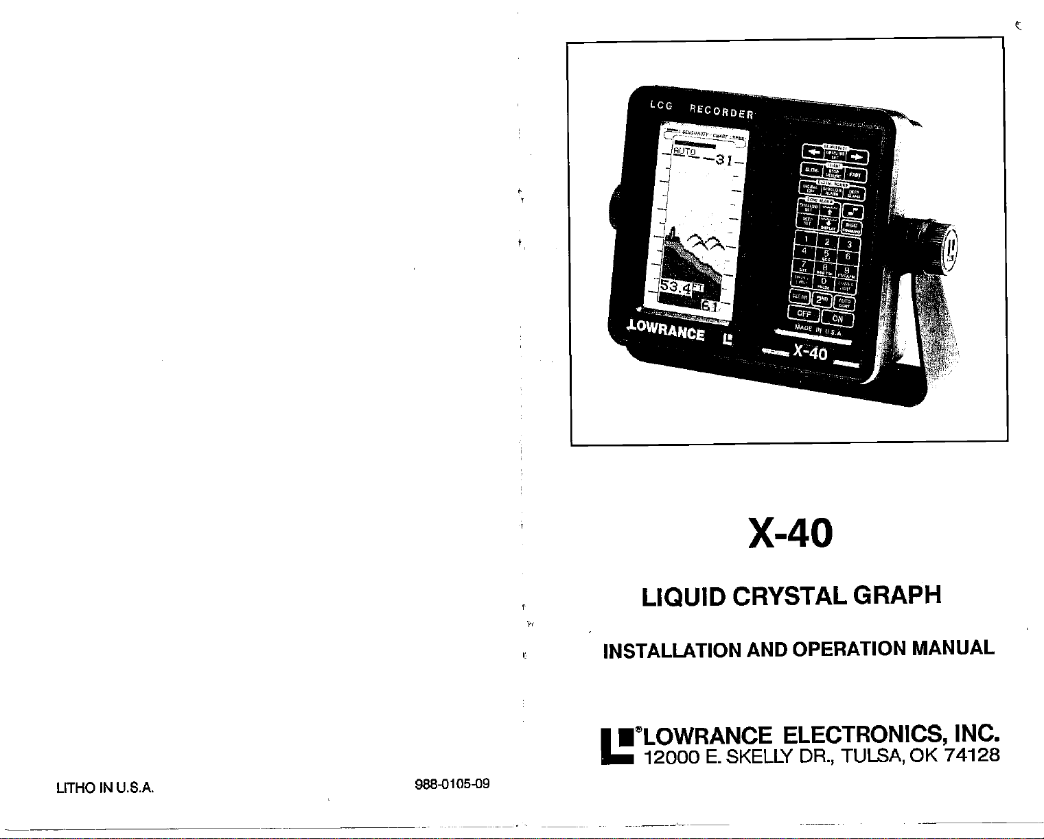
X-40
CRYSTAL
AND OPERATION
ELECTRONICS,
DR., TULSA,
UTHO
IN U.S.A.
LIQUID
INSTALLATION
•eLOWRANCE
12000 E. SKELLY
988-0105-09
PDF compression, OCR, web-optimization with CVISION's PdfCompressor
GRAPH
MANUAL
INC.
OK 74128
TABLE OF
POWER
NOISE
TRANSDUCER
KEYBOARD
DISPLAY
OPERATION
ON
CLEAR
AUTO
SENSITMTY
CHART SPEED
SCALE
RANGE
LOWER LIMIT
UPPER
AUTO BOTTOM
GRAYLINE
DIGITAL
TENTHS
ALARMS
NOTE KEY
ZONE ALARM
DEPTH ALARM
LIGHT
DiSCRIMINATION
8CC
FEET-FATHOMS-METERS
PULSE
COMMAND
MENU #1 - SPEAKER
MENU #2- GRAYLINE
MENU #3
MENU #4
TRANSDUCERS AND
SIGNAL
FISH SIGNALS
WATER
SURVEYING A LAKE
BAIT P1514
HOW
TO OBTAIN SERVICE
SCHEMATIC AND PARTS LIST
SPARE
SPECIFICATIONS
GLOSSARY
CONTENTS
CONNECTIONS 2
BASICS
INTERPRETATION
UM1T
TRACKING
VOLUME
-
SCALES
-
DIGITAL
INTERPRETATION
TEMP. AND
PARTS
CHECKS/LINES
AVERAGING
CONE ANGLES
THERMOCLINES
3
3
4
6
7
7
7
s
8
9
11
11
12
12
13
14
15
16
16
16
17
18
19
19
20
21
22
22
23
24
24
25
26
27
28
29
31
32
32
32
33
33
34
TRANSDUCER -The element of a sonar
energy
from the
echo strikes the
energy
TRANSOM MOUNT-
on ti .e transom o. t1
UPPER/LOWER
which is
1.
screen or
the lower limit
feet as the
VIDEO GRAPH
WINDOW
20
feet and a lower
ZOOM
-
A feature
transmitter Into ultrasonic
transducer,
received and
A method of
S I I...
e oat.
UMIT-These
paper.
-
The
upper
is at the bottom. For
limit and 30 feet as
upper
-
A
sonar unit that uses
A
segment
of the
limit of 50 feet creates
that
enlarges targets
it converts
displayed by
mounting
arethe
limit is shown
example,
the lower limit.
depth range.
system
that convertsthe
electrical
sound waves. When a
return
the sound waves into electrical
the sonar unit.
transducers or other sensors
limits
range
at the
displayed
of the
top
a 20 to 30 foot
a CRT or television
For
example,
display,
range
type
an
upper
on
the sonar
display.
has20
limit
a 30 foot window.
on the
display.
while
of
Copyright
© 1987 Lowrance
Elecfronios,
Inc. All
Rights
Res3rved.
37
PDF compression, OCR, web-optimization with CVISION's PdfCompressor
a 60 foot
REMOTE
has zero for the
range
-
An
Intelligent "repeater"
limit and 60 for the
upper
unit that receives
lower limit.
depth
from another sonar unit. A remote doesn't have a transmitter
However,
separately
RESOLUTION
it does have ft's own features that are
from the master.
-
The
of a sonar unit to
ability
separate targets
adjustable
other or the bottom.
-
RMS
A standard
SCALE
ofatarget, simply compare
markers on the
-
The
markings
display.
of transmitter
rating
on a sonar unit's
the
target's
power output.
display.
location to
To determine the
the location of the scale
information
or receiver.
and
operate
from each
depth
INTRODUCTION
Welcome to the world of
is a
high quality sonardesigned
X-40
automatically
by
by turning
just
finds and
it on. As
for both
displays
become
you
sportfishlng
professional
the bottom
familiar with
of its remarkable features. "Fine tune"
to
conditions
You can
shallower or
the most from
get
program
deeper
fish enters an alarm
each other.
Lowrance
Only
maximum
potential.
the X-40 to sound alarms
than a
preset depth.
zone. Zoom in and
gives you
your
the
sonar.
An alarm will also sound
separate
power
sonar.
Your Lowrance X-40
and novice users. The
depth,
your
the unit to
when the boat
fish from
to
adjust
and structure
fish,
try
some
X-40,
the surrounding
goes
when a
structure and
a sonar unit
to its
SECOND ECHO -Another echo that
of a
bottom,
returing
SECOND FUNCTION KEY
primary keys
other
function
SENSITIVITY
lncreasingthe sensitivity
echo. This is caused
target
strikingthe
surface of
by
thewater,
to the surface.
-
A button that converts the functions
on the
keyboard.
with two functions. You can switch functions
keys
key.
-
The
ability
Sonar unitswith a second function
of a sonar unit's receiver to
allows
weakertargets
registers
the sound
at
roughlytwice
waves
travellingtothe
to be
bottom
displayed.
the
depth
reflecting
off the
again,
of the
key
with the second
display targets.
Also called
"gain".
SCROLL SPEED - See CHART
SHOOT-THROUGH-HULL
sonar
signals
hull.
SUPPRESSION
ence or noise.
SURFACE CLARITY CONTROL- Reduces or eliminates undesirable
nals
displayed
THERMOCLINE
of water. Thethermocline
layers
to
pass through
-
A method used in some sonar unftsto
near the water's surface. Also called "SCC".
-Alayerofwatercaused bythe meeting
SPEED.
-
A transducer installation which allows the
a
fiberglass
providesthetemperature
hull without
cutting
a hole In the
eliminate interfer-
of warm
mostfish
and cool
prefer.
and
have
sig-
TogetstartedwithyourX-40,first
is where it all
begins,
the road. After
you've
and
improper
read these instructions
the rest of this manual in detail.
water,
when
the more
head to the lake.
you
X-40 will do for
your
INSTALLATION
Mounting
clearance when tilted for the best
allow wood screw
aluminum
back of thin
certain there is
transducer cables.
hole in the base of the
the
mounting
through
hole and
the bracket and dash.
rubberadhesive
the X-40 in
Install
or
panelswith
fiberglass panels
enough
You can route the
surface. The smallest hole
is
gimbal
Pass the transducer connector and
3/4".
bracket. Then
(RTV).
any
through
metal screws. Place a
sheet
room behind the unit to attach the
power
gimbal
After
routing
Offset the bracketto coverthe
to secure the
bracket. Then
readthe installationsection.
installation can cause
and installed
The more
you.
convenient
viewing angle.
bolt
mounting.
know when
you
Take this
location,
Holes in the bracket base
piece
mounting
and transducer
cables
pass
that will
push
the
the
cable wire down
power
cables,
fill the hole with silicone
problems
your
you get
manual
for reference
provided
Attach the
of
plywood
hardware.
through
them
through
one connector
pass
cable
up
majority
This
down
read
X-40,
to the
there is
bracket to
onthe
Make
the
and
7/B"
power
a hole in
through
of
the
through
the hole.
PDF compression, OCR, web-optimization with CVISION's PdfCompressor
36
1
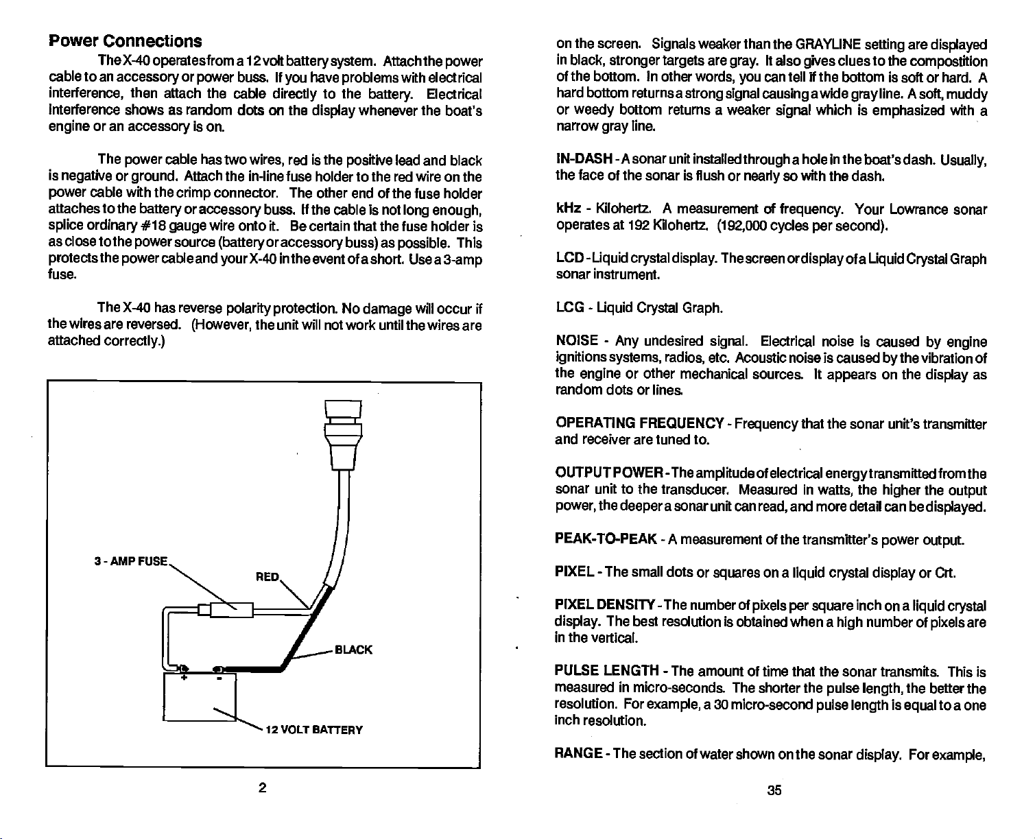
Power Connections
TheX-40
cable to an
interference,
Interference shows as random dots on the
engine
or an
operates
accessory
then
attach the cable
accessory
from a 12 volt
or
power
is on.
buss. If
directly
battery system.
you
have
problems
to the
display
Attach the
with electrical
battery.
whenever the
Electrical
power
boat's
on the screen.
in
black, stronger targets
Signals
of the bottom. In other
hard bottom
or
weedy
narrow
returnsastrong signal causing
bottom returns a weaker
line.
gray
weaker than the GRAYLINE
are
words,
It also
gray.
can tell if the bottom is soft or hard. A
you
signal
clues to the
gives
awide
which is
gray
setting
are
compostition
line. A
soft,
emphasized
displayed
muddy
with a
The
is
negative
power
attaches to the
splice
as close
protects
fuse.
the
wires are reversed.
attached
power
or
ground.
cable with the
ordinary
to the
the
power
The
X-40 has reverse
correctly.)
3-AMP
cable has two
crimp
battery
#18
gauge
source
power
cable and
red is the
wires,
Attach the in-line fuse holder to the red wire on the
positive
connector. The other end of
or
accessory
buss. If the
cable is not
wire onto it. Be certain that the fuse
(battery oraccessory buss)
yourX-40
polarity protection.
(However,
in the event of
No
the unit will not work until
lead and black
the fuse holder
long
enough,
holder is
as
possible.
a short. Use a
damage
will occur if
the wires are
This
3-amp
IN-DASH -A
the face of the sonar is
-
kHz
operates
-
LCD
sonar
-
LCG
NOISE
ignitions systems,
the
engine
random dots or
OPERATING FREQUENCY
and
receiver are tuned to.
OUTPUT POWER
sonar unit installed
flush or
Kilohertz. A
at 192
Liquid
crystal display. Thescreenordisplay
instrument.
measurement of
Kilohertz.
through
nearly
(192,000 cycles per second).
Liquid Crystal Graph.
-
Any
undesired
radios,
signal.
etc. Acoustic noise is caused
Electrical noise
or other mechanical sources. It
lines.
-
Frequency
-Theamplitude
of electrical
a hole In the boat's dash.
so with the dash.
frequency.
that the sonar unit's
sonar unit to the transducer. Measured in
power,
PEAK-TO-PEAK
the
deeper
PIXEL - The small dots
a sonar unit can
-
A measurement of
or
squares
read,
and more
the transmitter's
on a
liquid crystal display
Your Lowrance sonar
of a
Liquid Crystal Graph
is caused
bythe
the
on the
higher
appears
energytransmitted
watts,
detail can be
power output.
Usually,
by engine
vibration of
display
transmitter
as
fromthe
the
output
displayed.
or Crt.
12
VOLT BATTERY
2
PIXEL DENSITY -The number of
display.
in the vertical.
PULSE LENGTH
measured in
resolution. For
inch resolution.
RANGE
The best
-
The section of water shown on the sonar
resolution is obtained when a
-
The amount of time that
micro-seconds. The shorter the
example,
a 30 micro-second
pixels per square
35
inch on a
number of
high
liquid crystal
are
pixels
the sonar transmits. This is
pulse length,
pulse length
display.
the better the
is
equal
For
to a one
example,
PDF compression, OCR, web-optimization with CVISION's PdfCompressor
NOISE
GLOSSARY
ANCHOR WATCH
when the boat drifts
points.
A
into shallower or
selling
of the sonar unit's
deeper
-
BACKLIGHTEDAdisplayorkeyboardillUminatedfrombehitX1
Back-lighted displays
navigating.
CAVITATION
transducer
or
CHART SPEED
recorder.
graph. (Also
CONE ANGLE
transducerswith
-Air bubbles created
through
-(1)
The
(2)
speed
"scroll
called
-Width of the transducer's cone
coneanglesfrom 8to45degreesto
and
keyboards
water.
The
of an
speed
image
speed").
are essential
bythe high speed
of the chart
across the screen of a
alarm. The alarm activates
water than the alarm set
byalight.
when
night fishing
movement of a boat
a
on
paper
paper
liquid crystal
of sound. Lowrance
suitthevarying
of fishermen.
-
CRT
Abbreviation for Cathode
DEFINITION
resolution
-
The
display
of a sonar unit's
ability
can show
Tube.
Ray
more detail
See Video
display
Graph.
to show detail. A
than a low resolution one.
or
graph
has
needs
high
Minimize electrical noise
other
possible
generators
instrument
sources
is the
panel.
which radiates HF
power
pump
away
and transducer cables
can sometimes radiate
wiring
from those wires.
of electrical interference. One of
engine's wiring
harness
This
frequency) energy.
(radio
VHF radio antenna cables radiate
than even
power
cables.
speed
This noise is
the transducer.
rpm.
Usually,
noise. Thefasteraboattravets,
noise on the
owner's manual for
the
engine's wiring
and transducer cables as far
If interference
increases,
not
If the noise
air bubbles
display.
begins
then a
Stop
probable
electrical,
the
boat,
does not increase on the
passing
To eliminate
proper
routing
by
the
power
cable
the
harness that runs
usually
away
contains awirefor the
from the
noise so
RF
harness.
at slow boat
It
is
away
speeds, worsening
cause is acoustic noise,
but rather
put
mechanically
the
engine
overtheface of thetransducer
from the
For best
engine wiring.
to
try
keep
energy
important
as
at
higher power
to
possible
induced noise from
in
neutral,
display,
then
results, keep
the X-40's cables
and increase the
the moreair bubbles increaseand
this
problem,
mounting techniques.
read
from
away
largest
engine
noise
to the
tachometer
the
Also, bilge
levels
the X-40's
keep
from VHF radio
as the boat
or cavitation.
it is cavitation.
createacoustic
generate
the transducer
DISCRIMINATION
-
A feature
display onlytrue target
cuts out false
FISH ALARM
FISH ARCH
upsidedown
FLUSH MOUNT
bottom of the
signals
-
"V" orarch. This
transducer flush with the bottom
GIMBAL BRACKET
from other sonar, noise, thermoclines,
-
An alarm that activates
A sonar with
-
transom mount transducer
A
-
A bracket
The sonar unit can rotate
GRAYLINE -Thisfunction shows
PDF compression, OCR, web-optimization with CVISION's PdfCompressor
thatallows the sonar to eliminate
information.
Discrimination on
when a fish is detected.
resolution
good
distinguishesfish
used to install
displays
in the bracket for the best
the relative
34
Lowrance
fish
signalsfrom
that is installed
of the hull.
a sonar unit
viewing angle.
strength
of
signals displayed
noise and
products
and more.
signals
with an
othertargets.
with the
permanently.
TRANSDUCER
Installation
in a
separate package.
install the transducer.
instructions for the transducer are
Please
read the instructions
3
with the transducer
carefully
before
you
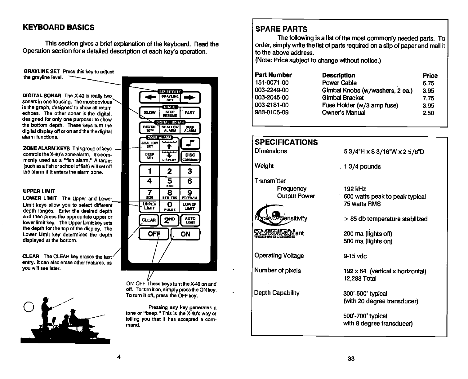
KEYBOARD
This section
Operation
GRAYLINE SET Press this
the
grayline
DIGITAL SONAR The
sonars in one
is the
graph, designed
echoes. The other sonar is the
designed
the
digital display
alarm
ZONE ALARM
controls the X-40's zone alarm. ft's
rnonly
(such
the alarm if It enters the alarm
UPPER LIMIT
LOWER
Umit
depth ranges.
and then
lowerlimit
the
Lower Limit
displayed
for
bottom
functions.
used as a "fish
as a fish or school of
LIMIT The
keys
press
key.
for the
depth
at the
BASICS
a brief
gives
section for a detailed
to
level.
housing.
one
only
depth.
off oron and
KEYS This
allow
you
Enter the desired
the
appropriate upper
The
top
determines the
key
bottom.
key
is
X-40
really
The mostobvious
to show all
purpose:
These
Upper
to show
turn the
keys
the the
group
alarm." A
will set off
fish)
zone.
and Lower
to select different
Limit
Upper
of the
keysets
display.
description
adjust
two
return
digital,
digital
cf
keys..—
corn-
target
depth
or
The
depth
explanation
of
SHALLOW
F
CLEAR][
of the
each
1
4
7
5121
UPPER
LIMIT
keyboard.
Read the
key's operation.
DIS PLAY
2
5
SOC
8
BTM TIlIC 9 I'T/FA/M
I)
PULSE
"ND
C
3
6
LowER
LIMIT
AUTO
11
JtI.IGHY
]
ON
SPARE
order,
to the
(Note:
Part
151-0071-00 Power
003-2249-00 Gimbal Knobs
PARTS
The
following
simply
above address.
Number
write the list of
Price
subject
is a list of the most
parts required
to
change
without
Description
Cable 6.75
notice.)
(w/washers,
003-2045-00 Gimbal Bracket
003-2181-00 Fuse Holder
(w/3 amp fuse)
988-0105-09 Owner's Manual
SPECIFICATIONS
Dimensions
Weight
Transmitter
Frequency
Output
Receiver
Operating
Sensitivity
Current
Power
5
3/4"H
1
3/4 pounds
192 kHz
600 watts
75 watts RMS
>
85 db
200 ma
500 ma
commonly
on a
slip
x 8
3/16W
to
peak
peak
temperature
(lights off)
(lights
on)
needed
of
paper
2
ea.)
x 2
5/8"D
typical
stabilized
To
parts.
and mail it
Price
3.95
7.75
3.95
2.50
CLEAR The
entry.
will see
you
C
CLEAR
erases the last
key
ft can also erase other
later.
features,
as
ON OFF
off. Toturn
To turn it
tone or
telling you
mand,
4
ThesekeystumtheX.4Oonand
iton,
simplypressthe Owkey.
off,
Pressing any key generates
"beep."
the OFF
press
This is the X-40's
that
it has
key.
accepted
way
a com-
a
of
Operating
Number
Depth
Capability
Voltage
of
pixels
9-15 vdc
192 x
64
(vertical x horizontal)
12,288
300'-SOO'
(with
500'-700'
with 8
Total
typical
20
degree transducer)
typical
degree transducer)
33
PDF compression, OCR, web-optimization with CVISION's PdfCompressor
 Loading...