

Page 1
Pub. 988-0160-451
Mapping GPS and Multimedia Player
Operation Instructions
Page 2

Copyright © 2007 Navico
All rights reserved.
No part of this manual may be copied, reproduced, republished, transmitted or distributed for any purpose, without prior written consent of
Lowrance. Any unauthorized commercial distribution of this
manual is strictly prohibited.
®
Navico
is a registered trademark and XOG™ is a trademark of Navico,
Inc.
Points of Interest Data in this unit are by infoUSA, copyright © 20012007, All Rights Reserved. infoUSA is a trademark of infoUSA, Inc.
Mapping Database, copyright © 2007 NAVTEQ. NAVTEQ ON BOARD
is a trademark of NAVTEQ.
Lowrance Electronics may find it necessary to change or end our policies, regulations and special offers at any time. We reserve the right to
do so without notice. All features and specifications subject to change
without notice. All screens in this manual are simulated.
For free owner's manuals and the most current information on this
product, its operation and accessories, visit our web site:
www.lowrance.com
Lowrance Electronics Inc.
12000 E. Skelly Dr.
Tulsa, OK USA 74128-2486
Printed in USA..
Page 3

Table of Contents
External Connections ............................................................... 4
Map Mode..................................................................................... 7
Creating and Saving Contacts............................................ 10
Saving Symbols On-screen.................................................. 11
Music Mode................................................................................ 14
Pictures, Gauge and Options ................................................ 17
Options Pages .......................................................................... 18
Directions List ......................................................................... 18
Categories Drawn.................................................................... 19
Route Via Destinations ........................................................... 20
Cancel Navigation ................................................................... 24
My Trails.................................................................................. 27
Language.................................................................................. 28
Safety Mode ............................................................................. 28
Sound and Voice Setup ........................................................... 28
Interface Setup ........................................................................ 29
Routing Options....................................................................... 32
Turn Preview ....................................................................... 33
GPS Simulator......................................................................... 34
Current Position Lock ......................................................... 35
EPE (Estimated Position Error)......................................... 35
Satellite Display .................................................................. 35
Lat/Lon Coordinates............................................................ 35
Searching, Finding and Navigating .................................... 36
1
Page 4

Auto Complete ......................................................................... 37
Name Filter.............................................................................. 40
Navigating to a Selected POI ................................................. 41
Recent Destinations ................................................................ 41
Finding Intersections .............................................................. 42
Choosing New Destinations while Navigating...................... 43
Point-to-Point Navigation ..................................................... 44
Create Waypoint at Current Position .................................... 46
Create Waypoint with Cursor ................................................ 46
Go To Cursor............................................................................ 47
Red Course Line ...................................................................... 48
Index......................................................................................... 56
2
Page 5

WARNING!
A CAREFUL NAVIGATOR NEVER RELIES ON ONLY ONE METHOD
TO OBTAIN POSITION INFORMATION.
CAUTION
When showing turn-by-turn navigation data, a GPS unit will show the
shortest, most direct route to the destination. There are times when it may
give directions, such as a U-turn, that may be prohibited in some locations. While navigating, a driver is responsible for noting all traffic signs
and obeying all local traffic laws. When following turn-by-turn directions,
a driver must take advantage of all available navigation tools, and must
visually check to make sure a clear, safe path to the next destination is
available.
WARNING:
Do not attempt to configure, adjust or enter information into
this unit while driving. Driver assumes all responsibility for
using safe and prudent driving and navigation methods. When
a GPS unit is used in a vehicle, the vehicle operator is solely
responsible for operating the vehicle in a safe manner. Vehicle
operators must maintain full surveillance of all pertinent driving conditions at all times. An accident or collision resulting in
damage to property, personal injury or death could occur if the
operator of a GPS-equipped vehicle fails to pay full attention
to travel conditions and vehicle operation while the vehicle is
in motion. Do not attempt to configure, adjust or enter information into your GPS unit while driving.
3
Page 6
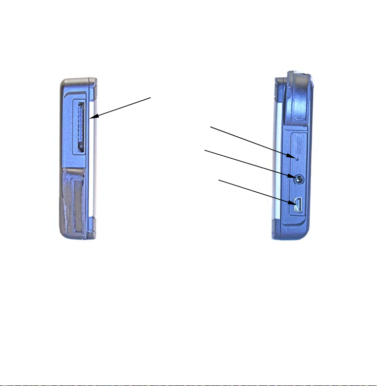
External Connections
Section 1 includes information on external connections.
SD card slot
Reset button
Headphone
socket
USB-to-PC/External
power socket
Left side of unit Right side of unit
SD card slot: To insert an SD card, hold it so the label faces forward and
slide it into the slot, pushing with the tip of the finger until the card
locks in place. To remove the card, again use your finger tip to push on
the card, releasing the catch and ejecting the card. When Music Mode
or the Pictures slideshow is selected, the unit will automatically search
the SD card for the related files.
4
Page 7
Reset button: If the unit is not responding, use the Reset button located
on the right side of the unit. Use the tip of a pen or something pointed
to firmly press the Reset button recessed in the hole. Pressing the Reset button will force the unit to power off so it can be restarted.
Headphone socket: Used to connect headphones. Listening to music or
turn-by-turn instructions with headphones can seriously impede your
ability to drive. Check local laws before using headphones.
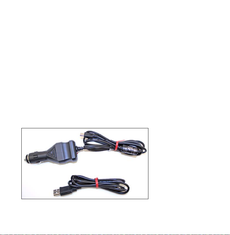
USB-to-PC/External power socket: The unit operates on an internal re-
chargeable battery. When the external power cable is connected the
unit draws power directly through the power cable and recharges the
battery. The unit also comes with a USB-to-PC cable. The XOG acts
like a removable disk drive when connected to a computer. The USB
cable is used to transfer files from a computer to the SD card. Additional SD cards will be needed to store music, picture and GPS files.
The external power
cable (top left) is
used to power the
unit in a vehicle. The
USB-to-PC cable
(bottom left) is used
to transfer data from
a computer to the
XOG's SD card.
5
Page 8

Portable Battery Charger
With a full charge, the internal battery will power the unit for approximately
2.5 hours. To extend battery time, try turning down the backlight. You can also
save power by turning off the satellite receiver from the Satellites screen. See
the topic Enable-Disable GPS on page 34.
An external power pack can be used to recharge the unit. There are two main
types of external power packs. One runs on replaceable AA batteries. The other
contains a built-in rechargeable battery. The external power pack must have a
USB connection and output 5 volts. In the case of replaceable AA types, the
power pack must hold 4 AA batteries.
6
Page 9
Map Mode
Section 2 addresses on-screen commands, power button, and creating
and saving contacts.
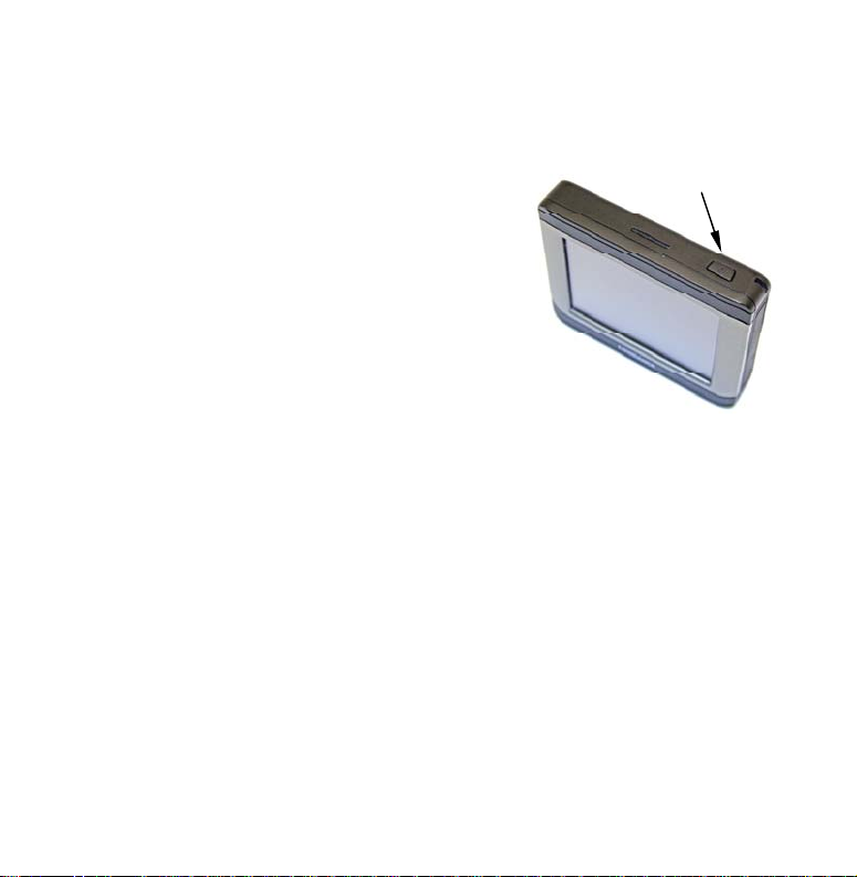
Power Button
The Power button turns the unit on and off
and controls the map screen's backlight.
The unit has three preset backlight levels.
Repeatedly pressing
POWER will cycle
through the backlight settings. To turn the
unit off, press and hold the
POWER key.
Touch Screen
The touch screen is used to enter commands. On-screen toolbars,
menus and text lists are used to select entries and change features.
From time to time there may be a slight delay between pressing a
command and seeing the unit respond. The delay may be necessary
while the unit retrieves information from the hard drive. Close menus
and dialogs by pressing
X in the top right corner of the screen.
Use an optional microfiber towel to clean the unit’s screen. DO NOT
use cleaning chemicals on the screen or damage may occur. Cleaning
fabrics other than a microfiber towel may scratch the screen. Damage
caused by incorrect cleaning is not covered by the warranty. To check
the availability of optional accessories go to our web site at www.lei-
extras.com.
7
Power button
Page 10
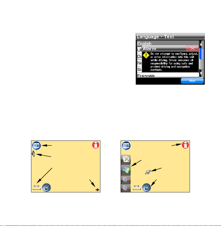
Opening Warning Dialog and Language Menus
The unit will display an Alarm dialog when
powered up. Press
X to close the dialog box.
The Language – Text menu will appear.
Select the text language the unit will display and press
NEXT. The Language – Voice
menu will appear. Select the spoken language for turn-by-turn voice instructions.
The unit will speak a short test message.
BACK to reselect the text language or
Press
DONE to continue to the map screen.
press
On-Screen Commands
When the map screen is touched, the cursor and Map Screen Toolbar
will appear. Use the cursor and Map Screen Toolbar to move around
the map screen. When the unit is navigating the cursor and Map
Screen Toolbar are hidden.
Main Menu button
Speak button
Auto Zoom button
Overlay Data Hide
button
Location-POI
Information button
Map Screen Toolbar
Cursor
Map Orientation
button
8
Page 11
Main Menu button: Map, Music, Find and Options are all available from
the Main Menu.
Location-POI Information button: Brings up the Location Information or
POI Information screen which is explained under the topic "Creating
and Saving Contacts."
Speak button: Push to repeat the current navigation instruction or to
bring up the on-screen volume control slider.
Auto Zoom button: As the map screen moves to track your position, Auto
Zoom will enlarge the map based on your speed and the distance to the
next turn. If you prefer to manually control the zoom level, turn the
Auto Zoom feature off by pressing the
AUTO ZOOM button. Turn the fea-
ture back on by touching the button again.
Map Screen Toolbar: Controls the map screen.
Cursor: Use to highlight map POI (Point of Interest) symbols.
Overlay Data Hide button: Clears Overlay Data Boxes from the screen.
Press it again to bring them back.
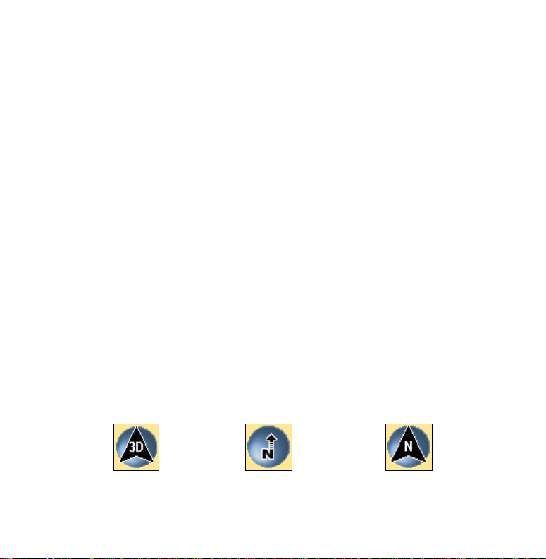
Map Orientation button: Toggles between three different map views. By
default, the unit displays the map in 3D view.
3D View North Up Track Up
9
Page 12
3D View displays the map from a position above, and slightly behind,
the black arrow icon which represents you on-screen. North Up always
shows the map with North at the top of the screen. Track Up rotates
the map so that the direction you are traveling is always at the top of
the screen.
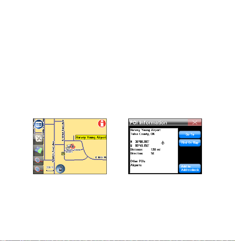
Creating and Saving Contacts
Use the POI Information screen to view information on POI symbols
and save contacts in the Address Book. Touch the map screen and the
cursor will appear. Use the cursor to select and highlight a POI symbol.
Press the
will appear. To save the POI in the Address Book select
BOOK
LOCATION-POI INFORMATION button. The POI Information screen
ADD TO ADDRESS-
in the POI Information screen.
The cursor (left) has been used to highlight a POI symbol. When the
Location-POI Information button is selected the POI Information
screen (right) will appear.
10
Page 13
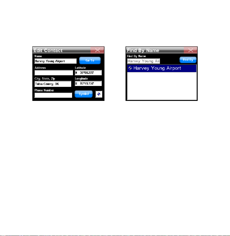
When
ADD TO ADDRESSBOOK is selected, the Edit Contact screen will ap-
pear with the option to Go To the selected location or add an on-screen
symbol by pressing the
SYMBOL button.
The Edit Contact screen (left) shows a saved contact. The Find By
Name screen (right) is the screen for saved contacts in the unit's Ad-
dress Book.
Saving Symbols On-screen
To save a symbol on the map, place the cursor where you want the symbol to appear on-screen. Press the
the Location Information screen press
LOCATION-POI INFORMATION button. In
ADD TO ADDRESSBOOK. The location
will be added to the Address Book and the Edit Contact screen will appear. Press the
SYMBOL button in the Edit Contact screen. The Symbol
Window will appear. Highlight and select a symbol. Close the screen.
The Edit Contact screen will appear. The symbol will appear in a small
window in the bottom right of the Edit Contact screen. When the Edit
Contact screen is closed the symbol will appear on-screen.
11
Page 14
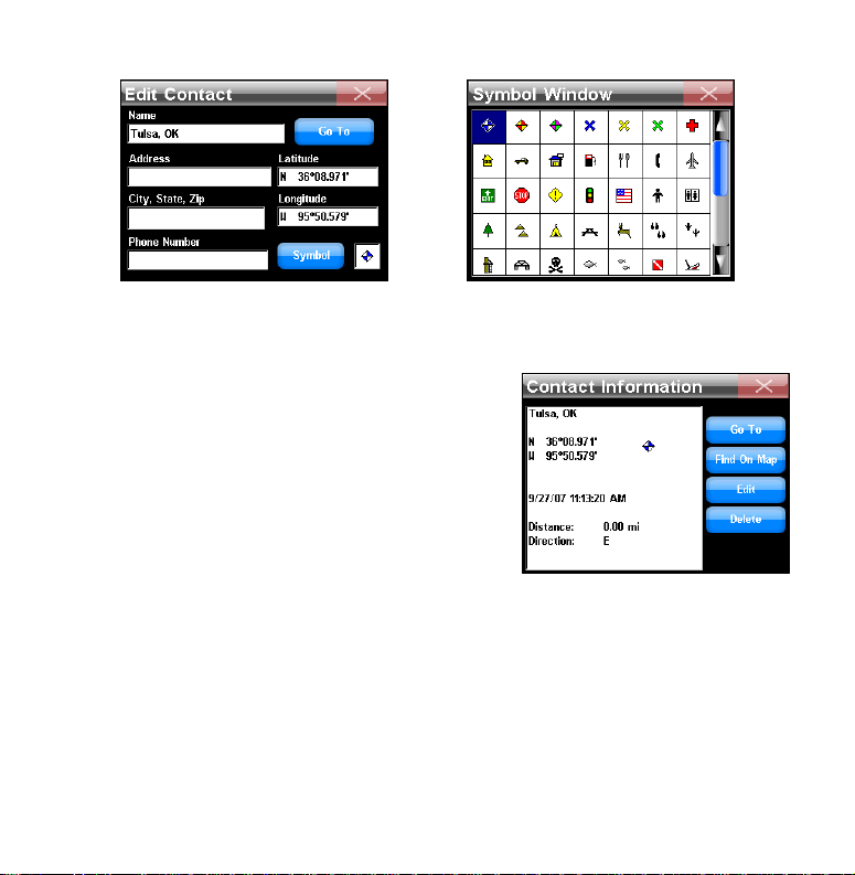
In the Edit Contact screen (left) press the Symbol button to bring up
the Symbol Window screen, shown at right.
The symbol will remain on-screen until it
is deleted or changed. To delete or change
a symbol, go to the Address Book. In the
Address Book highlight and select the contact to be edited. When the Address Book
entry is selected the Contact Information
screen will appear. The Contact Information screen has four buttons on the right
side: Go To, Find On Map, Edit and Delete.
Go To: Makes the unit navigate to the Address Book entry.
Find On Map: Displays the location on the map screen.
Edit: Changes information about an Address Book entry.
Delete: Deletes an icon or Address Book entry.
12
Page 15
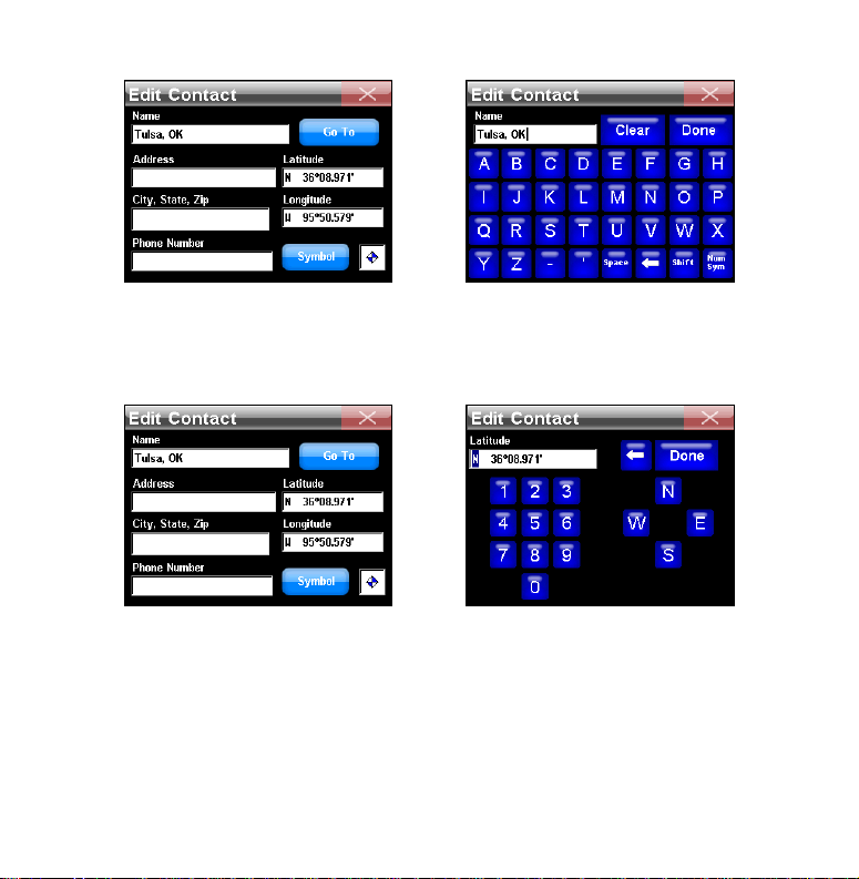
To change information about a saved contact touch the entry header
in the Edit Contact screen and a keyboard will appear. The Name
header was selected in the Edit Contact screen, at right, and a key-
board (left) appeared.
To manually change the latitude or longitude, press either the Lati-
tude or Longitude header and a numbers keyboard will appear.
13
Page 16
Music Mode
Use SD cards to store music and picture files. When Music Mode is selected the unit automatically searches the SD card for the specified
media files. Insert an empty SD card into the unit and use the USB-toPC cable to connect the unit to a computer. Once connected, the unit
acts like a removable disk.
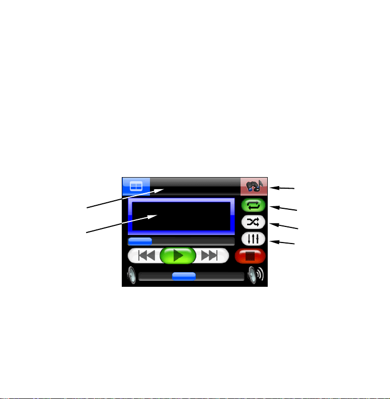
The Music screen has a central area for visualization effects with a set
of play control buttons along the right side and bottom of the screen.
When a song is playing the name of the song will appear at the top of
the screen along with the song's length and quality in kbps.
Find Music
Now Playing
box
Visualization
effects screen
Repeat
Shuffle
Equalizer
Music screen
14
Page 17
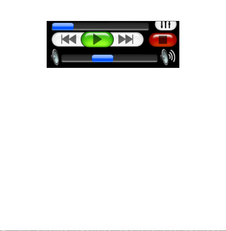
Song Position slider
Stop
Previous
Play / Pause
Next
Volume slider
Play control buttons
Previous: Skips to previous song.
Play/Pause: Starts a song or play list. If a song is playing, pressing this
button will pause the song.
Next: Skips to next song.
Stop: Stops the song.
Volume slider: Adjusts volume.
Song Position slider: Indicates the playback position of a song. Quickly
skip to any point in a song by pressing and dragging the blue button on
the Song Position slider.
Now Playing box: Displays the name, position and quality of the song.
Touch the screen inside the Now Playing box to open the Browse Music
Files screen.
Find Music: Opens the Audio Search screen. To find a specific song or
play list by its filename, press the
FIND MUSIC button and touch any-
15
Page 18

where inside the Name Filter box to open a keyboard. Enter all or part
of a song's filename and press
DONE. The Audio Search screen will pro-
vide a list of all audio files that match the text entered in the Name
Filter field.
Visualization Effects: Takes up the center of the Music Mode display and
provides either a Waveform Analyzer or Spectrum Analyzer effect. To
switch between the available visualization effects press the screen inside the Visualization Area.
Shuffle: When this feature is on, at the end of a song, the unit will ran-
domly choose another song to play next.
Repeat: When this feature is on, at the end of a song, the unit will start
playing the play list again from the beginning.
Equalizer: Use this feature to customize audio levels.
Browse Music Files screen
Touch inside the Now Playing box to launch the Browse Music Files
screen. The Browse Music Files screen shows the location of any music
file being played. Press
PLAY ALL to play all of the music files in a se-
lected folder.
16
Page 19

Pictures, Gauge and Options
The unit can display .gif and .jpg images stored on an SD card. The
unit will automatically search the SD card for any stored images. Se-
PICTURES located at the bottom left of the Main Menu screen. The
lect
picture toolbar controls are:
Close Slideshow returns to the Main Menu.
Zoom In enlarges the image.
Play / Pause cycles through the images.
Next Image
Previous Image
The toolbar can be hidden using the icon located in the bottom right
corner of the pictures screen.
Gauge Page
The Gauge Page shows the estimated time of arrival, time to destination, distance to destination, average speed and max speed. To view the
Gauge Page select
Menu screen. To return to the Main Menu press the
top left corner of the screen.
GAUGE PAGE located on the bottom right of the Main
MENU button in the
17
Page 20

Options Pages
The Options feature in the Main Menu contains three pages of menus
used to customize the operation of the unit.
Directions List
The Directions list is created when the unit begins navigating. The Directions list shows all the turns from the start of
a route to the end, including an arrow icon indicating the
direction of each turn.
The Directions List (left) and Turn Preview screen, at right.
18
Page 21

Use the blue slider bar in the Directions screen to scroll through the
list. The Turn Preview screen will appear when a turn is selected from
the Directions list.
Trip Calculator
Trip Calculator displays information about a route, including
current speed, average speed,
max speed, trip time and trip distance.
Pressing
RESET TRIP will reset all on-screen
values to zero. The Trip Calculator will
only track time spent and distance traveled
when you are moving faster than what the
Threshold level is set at.
Use the arrow buttons to the left and right of the Threshold level to
adjust its value. The Trip Active checkbox toggles the Trip Calculator
feature on and off.
Categories Drawn
Use Categories Drawn to select how much mapping detail to
display on the map screen. Map detail can include contacts,
points of interest, cities, highways, etc. Use the Categories
Drawn command to selectively turn any of these items on or off.
19
Page 22

Use the Map Categories Drawn screen to customize the map. In this
example the category My Trails and subcategory Distances are off. The
right image shows what Map Categories Drawn features have been
activated.
The Map Categories Drawn menu is divided into two columns, Category
and Subcategory. Press and highlight any item to turn it on or off. If a
category is turned off none of its subcategories will appear.
Route Via Destinations
Use Route Via Destinations to access the Routes menu where
routes are stored and managed. To create a route the unit
must know its position.
Once the unit has locked on, select
ROUTE VIA DESTINATIONS and the Routes menu will appear. Select NEW
ROUTE and the Edit Route menu will appear.
OPTIONS from the Main Menu. Select
20
Page 23

Use the Routes list menu (left) to store and manage different routes.
The left image shows several stored routes. Each route contains differ-
ent "legs." Each leg is a destination in the route. The Edit Route menu
(right) shows all of the routing controls and a generated route from
the Routes list. In this case it is the last route from the Routes menu.
The Edit Route menu has two options to choose from to find a location
and generate a route. Select either
FROM MAP or FROM FIND. If FROM MAP is
selected the map will appear.
Use the cursor arrow on the map screen and drag it to a specific location or address and select the
ADD button. A dialog box will appear indi-
cating the location has been added to the route. Continue to select and
add other locations in this same manner.
21
Page 24

Route Add
button
The Add to route button is shown at left. When you select a location to
add to a route, a Notice Via Added dialog (right) will appear.
Once all the locations are added, press the MAIN MENU button. Return to
the Route Via Destinations menu to access the route you created in the
Routes list. To begin navigating the route, highlight it and select
START
from the bottom of the screen.
To view the destinations in a particular route select
OPEN and the Edit
Route screen will appear. To delete a route from the Routes menu press
DELETE. If you select FROM FIND in the Edit Route screen the Find menu
will appear. Use this menu to search for a desired destination by Category and Subcategory.
22
Page 25

The Category and Subcategory list in the Find menu. In this example a
search is being conducted for a museum to add to a route.
Selecting a Category or Subcategory will bring
up the Find By menu (left) with three options:
Name Entry, Near Current Location and Near
Cursor. Depending on how you want to search
for a specific location will determine which option you should select.
The three Find By option screens.
23
Page 26

Choose a desired destination, select it, and add it to your route. You
can add 99 waypoints to a route. To rearrange the order of the waypoints in a route use the
UP and DOWN buttons in the Edit Route screen
to move a waypoint higher or lower in the list. The unit can generate a
route from several locations even if you don't know which order to go
in. Enter all of the destinations in any order and select
AUTOSORT. The
unit will organize the list of locations to create the shortest route.
Cancel Navigation
When a destination is reached, a dialog box will appear ask-
ing if the unit should cancel navigation. Select
YES to stop
navigating. Navigation can be canceled at any time with the
Cancel Navigation command. From the Options menu select
NAVIGATION and the unit will display a dialog box to confirm your choice.
Choose
YES and the unit will stop navigating. When navigating a route
CANCEL
with multiple destinations, and Cancel Navigation is selected, the unit
will give you the option to cancel navigation of the entire route or cancel navigation to the current destination and continue to the next destination in the route.
Navigation Mode
Instructions for switching between turn-by-turn and point-to-
point navigation modes are available in Section 6. Section 6
also explains how to use point-to-point navigation. The different map options for point-to-point navigation also are discussed.
24
Page 27

Overlay Data Setup
Overlay Data Boxes
Overlay Data Boxes appear in
semi-transparent boxes on the
map screen and are used to display information about a route, including
distance to the next turn, the direction and
angle of a turn, speed, estimated time to
destination and text directions. Control the
transparency level of Overlay Data Boxes
from the Interface Options screen.
The Overlay Data Setup (far left) can be found on Page 2 in the Options menu. If you select "(Add here …)" in the Overlay Data Shown
screen (center) the Data Viewer screen will appear. The Data Viewer
screen is shown far right.
Use the Data Viewer to select data to display on-screen. Press the +
sign to view the sub-categories listed under each main category.
25
Page 28

The Data Viewer screen left and center image. The Data Information
screen for the Odometer setting is shown at right.
When Audio Data (left image above) is selected its subcategories appear. Press in the box to the left of each category to activate it. When a
feature is activated (center image above) a check mark will appear in
the box next to it. The size of Overlay Data Boxes can be controlled
with the slider in the Data Information screen (far right). Each Data
Viewer category will have its own Data Information screen. Bring up
the Data Information screen by highlighting and pressing on the category in the Overlay Data Shown screen.
Move: Used to manually position data boxes on the map screen.
Auto Position: Automatically positions overlay data boxes on-screen.
Remove: Removes the overlay data box from the map screen.
Hide When Invalid (check box): Hides the overlay data box when it is not
valid.
26
Page 29

My Trails
The unit is designed to record Trails. By default, Trails are
hidden on-screen. Trails can be displayed, showing your
travel history. For instructions on displaying Trails see the
earlier discussion of Categories Drawn. For the My Trails feature to
work it must be activated in the Categories Drawn menu.
Visible Trail
(check symbol)
Active Trail
(arrow symbol)
Trails Menu (left) showing two trails. Trail 2 is the active trail, indi-
cated by the arrow to the right. Trail 1 is displayed on-screen, indi-
cated by the check mark to the left but it is not active. The Edit Trail
screen (right) allows you to modify an existing Trail.
My Trails controls how the unit records and displays Trails. The Trails
menu lists all the Trails, with symbols to indicate which trail is active.
To modify a Trail press its entry in the list. The Edit Trail screen will
appear. From the Edit Trail screen you can navigate a Trail, delete it,
rename it or modify its color, pattern and visibility.
27
Page 30

Language
Use the Language menu to select the text and spoken voice
language. When the Language button is selected, the Lan-
guage – Text menu will appear. The unit will display text in
English, UK English, Dansk, Nederlands, Suomi, Francais, Deutsch,
Italiano, Norsk, Portugues, Espanol and Svenska. Once the text language is selected, press
NEXT and the Language – Voice menu will ap-
pear. Use this menu to select what language the unit speaks when giving turn-by-turn instructions. When finished making your selection
DONE.
press
Safety Mode
The unit has a Safety Mode to prevent vehicle drivers from
operating the unit while a vehicle is in motion. The touch-
screen buttons are temporarily disabled whenever Safety
Mode is on. For more information about Safety Mode refer to the Auto
Safety Warning insert included with the unit's documentation.
Sound and Voice Setup
Use the Sound and Voice Setup
menu to adjust audio output. In
the Sounds menu, press inside
the box to the left of each feature to check
it (turn on) or uncheck it (turn off).
Key Sounds: When this feature is on the
28
Page 31

unit will emit a sound every time a command is entered.
Voice Instructions: If Voice Instructions are turned off, voice instructions
can still be accessed by pressing the
Verbose Mode: This feature will cause the unit to give slightly more de-
SPEAK button on the map screen.
tailed spoken navigation instructions.
Read Street Names: When this feature is active the unit will speak the
name of streets being navigated.
Read Distances: When this feature is active the unit will speak the dis-
tance to the next turn.
Music Volume: This setting only affects music playback; spoken instruc-
tions will remain unchanged.
Periodic Voice: Use this feature to increase or decrease the frequency of
spoken instructions. Voice instructions are repeated at set intervals
and are intended as reminders.
Voice Volume: This setting only affects spoken instructions; music vol-
ume will remain unchanged.
Master Volume: This setting affects all audio output.
Interface Setup
Interface Options controls the visual display of the unit, including brightness, contrast and the "graphical" skin.
29
Page 32

Interface Selection: Several skin options are available. To change the
skin display touch inside the Interface Selection box and a drop-down
list will appear showing all of the available skins.
Keyboard: Changes the keyboard button
Interface Options
button
layout.
Brightness: Controls the brightness of the
screen.
Transparency: Controls the transparency of
Overlay Data Boxes.
Light Timeout: Controls the screen's back-
light. When this feature is off the screen
will stay at a constant brightness. Moving
the slider to the left will cause the screen
to dim after a set amount of time. This feature is designed to save battery life.
Calibration Screen: If the touch screen isn't
responding correctly try calibrating the
screen. In the Interface Options menu
press the Calibrate Screen button. Touch Screen Calibration will appear with a small target icon. Press the target icon and a new target
icon will appear somewhere on-screen. Press each of the target icons in
turn. After the third time the screen should be calibrated.
30
Page 33

Power Key: Power Off and Standby
Power Off is the unit's default mode. Standby mode allows the unit to
"sleep" and draw very little battery power. If the unit is left idle for 12
hours, it will automatically leave Standby mode and switch to a full
shut down to save battery power. To place the unit in Standby mode,
select
screen. To place the unit back in Power Off mode select
STANDBY in the bottom right corner of the Interface Options
POWER OFF.
Units of Measure
This feature adjusts the units of
measure, including speed and
distance, heading, time and
date. The unit will not automatically update when traveling to a different time
zone. Access the Set Local Time feature
and use the up and down arrows to reset
the local time.
To change any setting, press the button next to the format. Depth is
available when using optional lake or coastal maps for point-to-point
navigation.
Reset Options
To reset all customizable settings to factory defaults, select
RESET OPTIONS. A dialog box will appear asking if you want to
"Reset all the options?" To reset all options select
YES. An-
31
Page 34

other dialog box will appear asking, "Do you want to clear your address
book?" Select
YES or NO depending on whether you want to clear all Ad-
dress Book contacts.
Device Information
To view the unit's software version, access the Device Information page.
Routing Options
Routing Options are used to control how the unit generates a
route. Use the three slide con-
trols to determine how much the unit
avoids or prefers the associated options
when generating a route. A Warning dialog
will appear when the Routing Options feature is accessed, stating, "Changing rout-
ing preferences can drastically alter routing
results and may significantly increase time
to calculate routes."
If the values are changed significantly and the unit begins generating
poor routes try using Reset to Defaults. The Recalculate Route button
can be used to automatically generate a new route to the same destination using new preferences.
32
Page 35

Cross-Traffic Turns: Use this option to avoid turns across busy lanes of
traffic.
Toll Roads: By default, toll roads have a fairly high value in routes gen-
erated by the unit. Drag the slider all the way to the right and the unit
will not use toll roads.
Interstates: The default setting is designed to avoid Interstates for short
trips but if the unit is sending you to the highway too often try setting
the unit to Avoid Interstates.
Turn Preview
The Turn Preview checkbox in the Avoid on Routs screen controls
whether or not the unit displays a Turn Preview. The Turn Preview
screen includes a close-up of the turn while data boxes provide text instructions about the turn. Access the Turn Preview for any turn in a
route from the Directions List.
Transfer Data
SD cards can be used to store and transfer GPS data files recorded on the unit. To transfer data to and from the SD card
TRANSFER DATA. A dialog box will appear asking, "Trans-
select
fer data which way?" The two choices are: Save or Load. When you
LOAD or SAVE the Transfer My Data screen will appear. Use the
press
dropdown box to select the filename of the GPS data file you want to
load. Use the Filename text box to enter a name for the data being saved.
33
Page 36

GPS Simulator
The GPS Simulator simulates the navigation of a route. If
the unit is in Simulator mode and you reach a speed of 15
m.p.h. or greater, and the unit acquires a satellite lock, the
unit will leave Simulator mode. If the unit does not have satellite lock
it will prompt you to simulate when navigation begins.
Satellites screen
Press the
Menu screen to access the Satellites screen.
SATELLITES button located in the top left corner of the Main
Satellites button
The Satellites screen (left) provides information on the satellites the
unit is monitoring to determine its position.
Enable-Disable GPS:
Turns the GPS feature on and off. If the GPS fea-
ture is Disabled it WILL NOT achieve satellite lock. The GPS feature
must be Enabled for the unit to get a position fix.
34
Page 37

Current Position Lock
Two buttons on the left side of the Satellites screen indicate the quality
of the units position lock. If 2D or 3D is not highlighted the unit may
not have a satellite lock.
2D lock does not include altitude. The unit must receive reliable signals
from 3 satellites to establish a 2D lock.
3D means the unit has achieved a more reliable lock, including altitude.
The unit must receive signals from 4 satellites to establish a 3D lock.
EPE (Estimated Position Error)
The Estimated Position Error, or EPE, represents the expected error
from a benchmark location. If the EPE shows 50 feet, then the position
shown by the unit is estimated to be within 50 feet of your actual location.
Satellite Display
A white circle serves as a graphical view of the satellites overhead.
Each satellite is shown on the circular chart relative to your position.
The GPS receiver is tracking satellites that are in light blue type. The
receiver has not locked onto a satellite if the number is in dark blue.
Lat/Lon Coordinates
Beneath the Satellite Display are the coordinates in latitude and longitude.
35
Page 38

Searching, Finding and Navigating
When Find is selected from the Main Menu, the first of three Find
menus will appear.
The unit can search for locations before it has acquired a position lock.
If a search is conducted before its position is determined, the unit will
display distance and bearing from the unit's last known location.
In the Find menus, search options are divided into specific POI categories: Gas, ATMs, Lodging, Restaurants, Shopping, Attractions and Airports have their own separate search screens. Use the Address menu to
search for POIs by street name, city, State, Province or zip code.
Keyboard
Search options in the Find menus require data, such as a shop name,
address, State or Province, to be entered. A keyboard will be used to
enter the information. The header of each Find Address screen will indicate what type of information should be entered.
36
Page 39

Select
y
DONE when the information is entered in the text field. The unit
may provide a list with more than one location/address that closely resembles the information entered. Scroll through the list and choose the
desired destination by highlighting and selecting it.
The button in the bottom right corner of
the keyboard, Num/Sym,
stands for Num-
bers and Symbols. This button toggles between the letters and numbers keyboards.
Auto Complete
The unit has an Auto Complete feature.
Before you finish entering an address,
state or province the unit may generate a
list of choices.
Num/Sym ke
Find Address
To search for a specific location, press the
ADDRESS button in the Find 1
menu. The Find Address screen will appear with the word Choose on-
screen, press
State or Province and press
CHOOSE and a keyboard will appear. Enter the name of a
DONE.
To see an alphabetical list of States or Provinces leave the
State/Province selection box empty and press
DONE. The unit will dis-
play an alphabetical list. Use the slider to scroll through the list and
make your entry.
37
Page 40

The unit will prompt you to search by State/Province. When the
Choose button is selected, a keyboard (right) will appear.
When a State or Province is entered another keyboard will appear. Use the keyboard to enter a City or Zip. Once the unit
has determined the city, it will prompt you
to enter an address. The unit will sometimes provide a list with more than one
address that closely resembles the one you
entered.
Scroll through the list of addresses provided by the unit and make your
selection. When an address is selected, a dialog box will appear with
three choices: Add to Addressbook, Find on Map and Go To.
Add to Addressbook: Saves an address in the Address Book.
38
Page 41

Find on Map: Displays a location on-screen. Anytime a search is per-
formed with the cursor, the distance will be calculated from the cursor
position and not the unit's current position.
Go To: Generates a route to a selected address.
Fuel, Lodging, Restaurants and other POIs
To find a local gas station, press
first Find screen. Now select
FIND from the Main Menu to open the
GAS, ATMS. A screen will appear with a list
of gas stations nearest to your current position. It may take a moment
for the unit to compile the list. Select a gas station from the list. The
POI Information screen will appear. Select
GO TO from the information
screen and the unit will generate a route to the gas station.
Use the Gas, ATMs command in the first Find menu to locate the near-
est gas station. The Nearest To Current Position screen (left) will appear. Scroll through the list and select a gas station. The POI Information screen (right) will appear. Select Go To and the unit will generate
a route to the gas station.
39
Page 42

The unit searches for locations in several different ways. When navigating, the unit searches for locations nearest to its current route. If
the cursor is on-screen the unit will search for locations nearest to the
cursor.
If you are not navigating, and do not have the cursor on-screen, the
unit will search for locations near your current position. To select a
specific search setting, press the
FIND BY button in the Nearest To Cur-
rent Position screen. The Find By menu allows you to search for a location by Name Entry, Near Current Location or Near Cursor.
Name Filter
If a search returns too many results, the Name Filter in the Nearest To
Current Position screen can help narrow a search. Press
NAME FILTER
and a keyboard will appear. Type all, or part, of the POI name and
DONE.
press
The unit will return to the previous list but will only show locations
whose names contain the text you entered. For example, a search could
be significantly narrowed by entering the word "Taco" in the Name Filter field. This will return results for the nearest restaurants with
"Taco" in its name, as shown in the following images.
40
Page 43

To search for a specific restaurant by name, select the Name Filter op-
tion; "Taco" search results are shown at right.
Navigating to a Selected POI
When a POI is selected the unit will display a POI Information screen
with details about the location. Press
FIND ON MAP to have the unit close
the POI Information screen and center the map on the selected POI. To
navigate to the POI press
GO TO and the unit will generate a route to the
destination.
Recent Destinations
Recent Destinations provides a list of the most recent destinations. Use the Find Recent screen to get back on route if
you diverted to another location during your trip.
41
Page 44

The Find Recent screen is shown at left. When a recent destination is
selected the Recent Destination Information screen appears.
Finding Intersections
Select
CHOOSE and a keyboard will appear. Enter the name of the
INTERSECTION to open the Find Streets screen. Select
first street without direction or street type modifiers such as
"N." for North or "Ave." for Avenue. Press
DONE and another
Find Streets screen will appear with a dialog directing you to enter the
name of the second street. Press
the name of the second street. Press
SPELL and use the keyboard to enter
DONE and a dialog box will appear
stating, "Finding street intersection. Please wait."
If the unit is not able to locate the intersection a dialog box will appear
indicating it was unable to locate the intersection. When the unit locates the intersection a dialog box will appear stating, "Please choose
an option." You will have three options: Add to Addressbook, Find on
Map or Go To.
42
Page 45

Choosing New Destinations while Navigating
When navigating and an alternate destination is selected a dialog box will appear
asking, "Which would you like to do?" You
will have three choices: Detour here, New
final destination or Cancel old navigation.
Detour here: Navigates to the new location.
Once you arrive, the unit will resume navigating to the original destination.
New final destination: Will add a new location to the end of a route.
Cancel old navigation: Will stop navigating to the original destination
and start navigating to a new location.
43
Page 46

Point-to-Point Navigation
The unit can use optional "plug and play" map cards available through
LEI, the source for Lowrance accessories. Optional maps include: NauticPath™ USA marine charts, Fishing Hot Spots
Navionics
Europe, and LakeMaster
Caution:
®
marine charts, FreedomMaps™ for North America and
The unit is designed to be used inside an automobile. The mounting
bracket included with the XOG package is not designed for boats, motorcycles or off-road vehicles. These installation types require an optional bracket and cradle designed for rugged outdoor use. The unit's
case is not waterproof. If used in wet conditions the unit must be protected from moisture.
®
ProMaps.
The unit also can display custom maps prepared by LEI's MapCreate™
topographical mapping software and Lowrance Enhanced Lake Maps
that can be downloaded free from the Lowrance web site,
www.lowrance.com. Turn-by-turn navigation does not work with any of
these optional maps.
When using optional maps, you must search for POIs using the
ALL POIS BY NAME button in the Find 2 menu. Other search categories
will not work. If a POI symbol is selected on the map screen with the
cursor, pressing the Location-POI Information button displays a POI
information screen for that item.
®
Elite lake maps,
SEARCH
44
Page 47

Navigation Modes
Point-to-point navigation creates a straight-line navigation
course between you and another point on the map screen. To
switch to point-to-point mode, press the
OPTIONS. From the Options menu select the NAVIGATION MODE button
select
MAIN MENU button and
to display the Navigation Mode screen.
Turn-by-turn is selected as the default setting. When Point-to-Point is selected, a dialog appears asking if you want to change
modes. Choose
YES and close the Naviga-
tion Mode screen. Settings in the Map
Data pull-down menu do not need to be
changed unless a Navionics card is used.
When a Navionics card is inserted, the Map Data pull-down menu becomes active. Scroll down and select Navionics, now close the Navigation Mode screen. To switch back to turn-by-turn, go to the Navigation
Mode screen and select
WARNING:
In point-to-point mode the unit will display the shortest, most
direct path. The unit provides navigation data to waypoints
regardless of obstructions.
TURN BY TURN.
45
Page 48

Straight-line Navigation Commands
The two basic commands used for straight-line navigation are Go To
Cursor and Go To Waypoint. Go To Cursor will navigate to any spot,
landscape feature or waypoint selected on-screen using the cursor. The
Go To Waypoint command works with the Address Book feature.
Create Waypoint at Current Position
Press the
Waypoint Information screen will appear. Select
LOCATION-POI INFORMATION button on the map screen and the
ADD TO ADDRESSBOOK to
save the waypoint. The Edit Contact screen appears. You can accept
the default name and symbol or edit it.
Waypoint Information screen, at left. The Edit Contact screen for this
waypoint is shown at right. To change the waypoint name, symbol or
any other information in the Edit Contact screen, touch anywhere in-
side the relevant box and a keyboard will appear.
Create Waypoint with Cursor
Use the cursor to select a location on-screen. Press the
LOCATION-POI IN-
46
Page 49

FORMATION button to bring up the Waypoint Information screen. Select
ADD TO ADDRESSBOOK to save the waypoint. The Edit Waypoint screen ap-
pears. Select
X to close the screen and clear the cursor and toolbar from
the screen.
Navigate To a Waypoint
If a waypoint cannot be viewed on the map screen, the easiest way to
navigate to the waypoint is to look it up in the Address Book. Press the
MENU button, select FIND and choose ADDRESS BOOK. The waypoint can be
found one of three ways.
• Drag the slider bar to scroll down the list and select the waypoint.
• To search by name, touch the
FIND BY NAME box to launch the keyboard.
Enter the waypoint name to find it in the Address Book.
• The FIND BY button gives you the option to search by name or narrow
the search by looking near your current location or near the cursor location. Select the waypoint and the Waypoint Information screen appears. Choose
GO TO and the unit creates a red course line from your
current position to the waypoint.
Go To Cursor
Use the Go To Cursor command to navigate to a waypoint on the map
screen. Highlight a waypoint on-screen with the cursor and press the
LOCATION INFORMATION button. Now choose GO TO.
47
Page 50

Waypoint
Black arrow icon
Navigating with the Go To Cursor command. At left, a waypoint was
selected with the cursor. The image at right shows the straight-line
navigation course.
Red Course Line
The turn-by-turn magenta line is replaced with a red course line in
point-to-point mode. An "S" symbol is placed at the starting point. To
navigate a red course line, zoom the map screen in closely and steer so
the black arrow icon moves along the red course line. An arrival alarm
will sound when the destination is reached. Cancel navigation by going
to Options Page 1 and pressing
CANCEL NAVIGATION.
Steering Arrow and other Overlay Data
Different types of navigation information can be displayed as Overlay
Data. Overlay Data boxes will not appear in point-to-point mode unless
the Hide When Invalid setting is turned off. To do this, go to Options
Page 1 and select
OVERLAY DATA SETUP. In the Overlay Data Shown menu,
select the desired overlay type to display its Data Information screen.
48
Page 51

Uncheck
HIDE WHEN INVALID and close the menus. Some overlay categories
do not work the same in point-to-point mode, but several data types can
help guide you. One of the easiest to use is the Steering Arrow. The
Steering Arrow shows which way to steer to a destination.
It always points to the destination, regardless of the map orientation. The arrow
automatically shows the distance from
your current position to the destination. In
addition to the Steer arrow, the most commonly used overlay data for point-to-point
navigation are:
Track: The direction traveled; shown in de-
Steering Arrow
grees, true or magnetic format.
Bearing: The direction to a destination from your current position;
shown in degrees, true or magnetic format.
Course: The direction traveled to reach a destination.
Off Course (Pos Error): Distance to the left or right of the course line
when not directly on the course line.
Navigating With Trails
Displaying and editing trails is discussed under the topics Categories
Drawn and My Trails. A trail is a history of the path you have taken
and is represented by a dotted line extending from the back of the black
49
Page 52

arrow icon. The unit creates a Trail line by recording a string of trail
points along your path. The unit can save 100 trails with 10,000 points
per trail. The default setting is 2,000 points per trail. When the trail
exceeds the maximum point setting, the unit will begin recording a
trail over itself. Up to 100 Trails can be saved to an SD card. Trails can
then be deleted from the unit's memory and a new set of trails recorded. GPS data files can be backed up on a computer using the USBto-PC cable.
Trails can be reloaded from an SD card to the unit's memory. To preserve a Trail from Point A to Point B, first create a new trail at Point A.
Go to Options Page 2, select
MY TRAILS and press the NEW TRAIL button.
When you arrive at Point B, stop recording and save the trail just created. This happens automatically when you start another trail with the
NEW TRAIL button.
The two ways to navigate a saved Trail are "visual trailing" and the
Navigate Trail command. Visual trailing is the easiest. Zoom the map
in closely so the trail is clearly visible. Begin moving and glance at the
map screen. Walk or steer so the black arrow icon stays on the Trail
line. The Navigate Trail command converts a trail into a route. Select
MY TRAILS. When you select a trail from the Trail Menu the Edit Trail
menu will appear. Press the
pears. With the first point in the route selected, press the
NAVIGATE button. The Edit Route menu ap-
DIRECT TO but-
ton and the unit begins navigating.
50
Page 53

From left to right, menu sequence for navigating a trail.
At the start of a trail the arrival alarm will sound as soon as navigation
begins. Press
X to clear the alarm. Begin navigating by following the
red course line. Back tracking a trail requires manually editing the
route to change the point order. To back track, begin with the same
steps for navigating a trail forward but in the Edit Route menu the route
order will need to be changed.
NauticPath™ USA Marine Electronic Charts
NauticPath™ USA map cards show offshore/coastal navigational detail.
This plug and play map card provides electronic charts covering the
U.S. East and West coasts, Hawaii, Gulf coast, Great Lakes, Alaska,
the Bahamas, Puerto Rico and the U.S. Virgin Islands.
NauticPath features depth contours, intertidal zones and spot soundings, navigational aids with view range and coverage. Extensive objectoriented detail can be viewed, including list of lights, tides and currents, wrecks and obstructions, marine services, restricted areas and
anchorage database information.
51
Page 54

These images show the offshore/coastal detail using NauticPath™ USA
marine charts.
Reading NauticPath Map Information
Use the cursor to highlight a map feature or symbol and a pop-up box
will appear identifying the item. Press the
LOCATION-POI INFORMATION but-
ton. A screen appears with information about the selected item.
The Miami Harbor Entrance tide symbol in the left image has been
highlighted. At right, the Location-POI Information button has been
selected to view tidal information.
52
Page 55

Information for almost any on-screen symbol can be accessed as long as
it can be highlighted with the cursor. The Tidal Current Information
screen displays daily tidal current data for specific stations on this date
at the present time. The graph at the top of the screen is an approximate view of the flood and ebb pattern for the day, from midnight
(MN), to noon (NN) to midnight (MN). Slack water, the period of little
or no current, is represented by the Slack Water Line (SWL). The flood
appears above the SWL and the ebb appears below the SWL. Look up
tidal current data for other dates by changing the month, day and year
selection boxes at the bottom of the Tidal Current Information screen.
The cursor has selected the Port Aransas Municipal Harbor marina
symbol, at left. In the right image, the Location-POI Information but-
ton has been selected to view information on the marina.
Fishing Hot Spots® Elite Mapping Data
Fishing Hot Spots' electronic charts contain detail for various U.S.
lakes. Enhanced shorelines and underwater depth contours are included in Fishing Hot Spots' databases.
53
Page 56

Fishing Hot Spots electronic charts lake detail, far left. Select a Fish-
ing Area POI symbol and press the Location-POI Information button
for localized fishing tips, center. Select a Marina symbol to get infor-
mation about the marina's services, far right.
Mapping data includes Fishing Tips & Techniques, Lake Profile and
local Fishery information.
Enhanced Lake Maps
U.S. inland lake contour maps can be downloaded for free from
www.lowrance.com. In addition to underwater contour features, these
maps show shoreline features, small islands and various bottom struc-
54
Page 57

tures. More detail appears as the screen is zoomed in. Underwater features on man-made lakes reflect conditions prior to inundation. The
amount of detail varies from lake to lake.
Underwater features, such as bridges, old creek channels, roads and
other items can be identified with the cursor.
FreedomMaps™ and MapCreate™ Mapping Data
MapCreate™ Topo software can be used to create custom maps for
loading onto SD cards. MapCreate version 6.3 includes topographic elevations for 49 states, excluding Alaska.
MapCreate version 7 has elevations for all 50 states. Topographic information is displayed as major and minor contour lines with numbers
showing the elevation above sea level. The same data is available in
plug and play FreedomMaps.
55
Page 58

Auto Complete, 36
Auto Zoom, 8
Brightness, 28, 29
Calibrate Screen, 29
Cancel Navigation, 23
Contact, 9, 10, 18
Contrast, 28
Cursor, 7, 38, 39
Customize Display, 32
Destinations, 19
Directions List, 17, 32
External Connections, 4
Find Address, 36
GPS Data File, 32
Icons, 17, 26, 29
Keyboard, 15, 29, 39
Language, 27
Location-POI Information Button, 8
Location Information Screen, 9
Main Menu, 8
Map Mode, 7
Memory Cards (MMC), 4, 5, 13, 32
Music Mode, 13
Name Filter, 39
NauticPath, 50
Navigating, 26
Now Playing Box, 14
Options, 17
Overlay Data, 24
Pictures, 16
Play Control Buttons, 14
POI (Point of Interest), 18, 38, 40
Point-to-Point Navigation, 43
Power, 6
Reset Options, 30
Route, 17, 18, 19, 20, 23, 31, 32, 33, 39
Routing Options, 31
Safety Mode, 27
Satellites Screen, 33
Screen Calibration, 29
SD card, 4
Searching, 14, 35, 36, 38, 39, 40
Simulator, 33
Sound and Voice Setup, 27
Straight-Line Navigation, 44
Symbols, 10
Touch Screen, 6,
Trail, 26
Transfer Data, 32
Trip Calculator, 18
Turn Preview, 18, 32
Units of Measure, 30
USB-to-PC Cable, 13
Utilities, 18
Keyboard, 35
Visualization Area, 15
Waypoints, 23, 45
56
Page 59

Page 60

Lowrance Pub. 988-0160-451 © Copyright 2007
All Rights Reserved
Printed in USA 101207 Navico
 Loading...