

Lowrance electronic LRA-2400, LRA-1800 User Manual
Pub. 988-0161-10B
Radar Operation
Instruction Manual

Copyright © 2008 Navico.
All rights reserved.
No part of this manual may be copied, reproduced, republished, transmitted or distributed for any purpose, without prior written consent of
Navico. Any unauthorized commercial distribution of this man-
ual is strictly prohibited.
®
Lowrance
is a registered trademark of Navico. NMEA 2000® is a regis-
tered trademark of the National Marine Electronics Association.
Navico may find it necessary to change or end our policies, regulations
and special offers at any time. We reserve the right to do so without notice. All features and specifications subject to change without notice. This
manual covers all display units compatible with Lowrance Radar at
press time.
For free owner's manuals and the most current information on
this product, its operation and accessories,
visit our web site:
www.lowrance.com
Navico
12000 E. Skelly Dr.
Tulsa, OK USA 74128-2486
Printed in USA.

Table of Contents
Warnings and Cautions .......................................................... iii
Section 1: Introduction............................................................. 1
Software Update............................................................................ 1
Checking Software Version....................................................... 1
To download software update to MMC/SD card: ................. 1
To update display unit software: .......................................... 2
How to use this manual: typographical conventions .................. 2
Basic Radar Display Components ................................................ 3
Section 2: Radar Setup ............................................................. 5
Getting Started.............................................................................. 5
To access Radar Page: ........................................................... 6
Auto Power-On .............................................................................. 7
Turning on/off Auto Power-On: ............................................ 7
Radar Setup ................................................................................... 7
Trigger Delay Preparation........................................................ 8
Range...................................................................................... 8
Gain ........................................................................................ 8
Anti-Sea Clutter .................................................................... 8
Anti-Rain Clutter .................................................................. 8
Trigger Delay ......................................................................... 8
Adjust Trigger Delay................................................................. 9
Adjust Heading Line ............................................................... 10
Adjust Tune ............................................................................. 11
Section 3: Basic Operation .................................................... 13
Pages ............................................................................................ 13
Radar Only............................................................................... 13
Digital Data ............................................................................. 13
Radar with Map....................................................................... 13
Radar with Sonar .................................................................... 14
Radar with Gauges.................................................................. 14
Radar, Map and Sonar ............................................................ 15
Radar Menu ................................................................................. 15
Gain .......................................................................................... 15
Anti-Sea Clutter (STC)............................................................ 16
Anti-Rain Clutter (FTC).......................................................... 16
Interference Rejection ............................................................. 17
Radar Range ............................................................................ 17
Radar Echo Expansion............................................................ 18
Echo Trail Interval .................................................................. 18
Clear Radar Trails................................................................... 18
To clear radar trails: ........................................................... 18
i

Log Radar Data ....................................................................... 18
Radar Setup ............................................................................. 22
Radar Orientation ................................................................... 22
Radar Color Scheme................................................................ 22
Adjust Antenna Park .............................................................. 22
Radar Information................................................................... 23
Radar Power ............................................................................ 24
Turns the radar on and off...................................................... 24
Radar Simulator ...................................................................... 24
Radar Overlay ............................................................................. 25
Radar Options menu ............................................................... 25
Overlay Options menu ............................................................ 26
Section 4: Advanced Operation ............................................ 27
Reading the Display .................................................................... 27
Gain .......................................................................................... 27
Range Rings............................................................................. 27
Anti-Sea Clutter (STC)............................................................ 28
Anti-Rain Clutter (FTC).......................................................... 28
Electronic Bearing Line (EBL) ............................................... 28
Variable Range Markers ......................................................... 28
Radar Cursor ........................................................................... 28
Appendix I: Glossary............................................................... 33
ii

Warnings and Cautions
Caution:
Use this radar at your own risk. This radar was designed for
use as a navigation aid. It should not be used for purposes that
require precise measurements of direction, distance, topography
or location. Always compare the navigation information received
from your radar with data from other navigation aids and
sources. When a conflict arises between the navigation data from
your radar and data from other navigation aids, make sure you
resolve the conflict before proceeding with navigation. A CARE-
FUL NAVIGATOR NEVER RELIES ON ONLY ONE
METHOD TO OBTAIN NAVIGATION INFORMATION.
Caution:
International Regulations for Preventing Collisions at Sea mandate that when radar is on a vessel, the radar must be used at
all times, regardless of weather conditions or visibility. Numerous court decisions have not only ruled the radar must be used,
but that the radar operator must be knowledgeable in all operational aspects of radar performance or otherwise face a greater
risk of liability if an accident occurs.
Caution:
If you purchased an open array radar antenna, make sure it is
installed in an area free of hardware obstructions and free of potential obstructions like sails, lines or other vessel components
that could intermittently intrude or be caught up in the array
antenna's rotation path.
WARNING: High Voltage Hazard
Dangerously high voltages are present within the radar
scanner unit. Technicians must exercise extreme care
when working inside the unit. ALWAYS remove power
before removing the cover. Some capacitors may take
several minutes to discharge, even after switching off
the radar. Before touching the magnetron or any high
voltage components, ground them with a clip lead.
iii

WARNING: Microwave Radiation Hazard
The microwave energy radiated by a radar antenna is
harmful to humans, especially to the eyes. NEVER look
directly into an open waveguide or into the path of radiation from an enclosed antenna. Radar and other radio frequency radiation can upset cardiac pacemakers.
If someone with a cardiac pacemaker suspects abnormal
operation, immediately turn off the radar equipment
and move the person away from the antenna. Turn off
the radar whenever it is necessary to work on the antenna unit or other equipment in the beam of the radar.
WARNING: Turn Off Radar When Docked
The radar beam can be harmful to humans in close proximity (within 20 yards, or 18.3 meters). When docked, be
considerate of other boats and pedestrians nearby and
remember to turn off your radar. If your boat is in a covered marina and the radar is on, a metal roof can act as
a reflector, bouncing microwave energy back at your
boat and passengers.
iv

Section 1: Introduction
Your radar consists of four components: the radar scanner unit (antenna),
your display unit (sold separately) radar processor and RIM 300 radar
interface module. This manual covers LRA-1800 and LRA-2400 radars.
WARNING:
Radar radiation can be harmful to you and bystanders.
Radar misuse or misunderstanding radar operation
could lead to a collision, which could result in property
damage, personal injury or death.
You must be familiar with the procedures and all warnings and cautions described in the installation and operation manuals in order to operate your radar safely
and effectively.
The following units are compatible with LRA-1800 and LRA2400 radars: LCX-113c HD, GlobalMap 9300c HD, LCX-112c, Global-
Map 9200, LCX-38c, GlobalMap 8300c, LCX-37c, GlobalMap 8200c,
GlobalMap Baja 840c, LCX-28c HD, GlobalMap 7300c HD, LCX-27c,
GlobalMap 7200c, LMS-520c, LMS-522c iGPS, LMS-522c iGPS IceMachine, LMS-525c DF, LMS-527c DF iGPS, Globalmap 5200c,
Globalmap 5300c iGPS, Globalmap Baja 540c, X510c and X515c DF.
Note for GlobalMap users: Menus and commands in your unit are
very similar to those shown in this manual, except your display will not
have sonar page, sonar alarm or sonar simulator options.
Software Update
If your display unit's software version is less than 2.2.0, you will need
to update the unit's software. To update your unit, contact your dealer
or download the update from our web site, www.lowrance.com.
Checking Software Version
1. With the display unit turned on, press
keys to highlight
2. Use the arrow keys to select
The software information screen will appear. If the version of software
listed on the software information screen is less than 2.2.0 you need to
update your display unit.
To download software update to MMC/SD card:
1. Log onto www.lowrance.com. Click on the PRODUCTS tab.
2. Select
MARINE and then click on your display unit's category.
SYSTEM SETUP and press ENTER.
SOFTWARE INFORMATION and press ENTER.
1
MENU twice, use the arrow

3. Select your display unit icon and choose
DOWNLOAD button next to the desired software update.
DOWNLOADS. Click on the
4. Follow the onscreen installation instructions to download the update
onto your MMC/SD card.
To update display unit software:
1. With the display unit turned off, install the MMC or SD card that
contains the radar software update.
2. Turn on the unit and the update will install automatically.
3. When the update is finished, the unit will power up normally. After
the update is complete, remove the update MMC from the card slot.
The update program will be erased automatically when the process is
complete. You can now use this card to record sonar logs or GPS data.
NOTE:
Lowrance continues to regularly develop display enhancements and
new radar features. We recommend you periodically check our
web site for the latest free radar software updates.
How to use this manual: typographical conventions
Arrow Keys
The arrow keys are represented by symbols (↓ ↑ ← →).
Keyboard
When a key needs to be pressed, the key is shown in bold. For example,
the "Enter/Icons" key is shown as
MENU.
Menu Commands
A menu command or a menu option will appear in small capital letters, in
a bold sans serif type like this: ROUTE PLANNING.
Instructions = Menu Sequences
Instructions for accessing the My Trails menu would look like this:
1. From the Map Page, press
Step 1 (above) means: "From the Map Page, press the Menu key twice.
Select (highlight) My Trails menu and press Enter."
ENT and the "Menu" key is shown as
MENU|MENU|↓ ↑ to MY TRAILS|ENT.
2
A
A
V
V
Range
Display
mode
Radar
Cursor Boxes
Electronic
Bearing
Lines
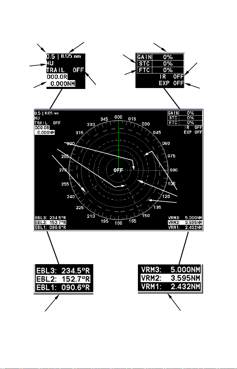
Basic Radar Display Components
Range Ring Interval
nti-Sea
Clutter
nti-Rain
Clutter
Echo Trail
status
Gain level
Range
Markers
Interference
Rejection
status
Radar Echo
Expansion
status
ariable
Your unit has three electronic bearing
lines and three variable range markers.
Electronic Bearing Line position
for EBLs 1, 2 and 3. Highlighted
in white, EBL 2 is the active bearing line.
An enlarged example of EBLs and
VRMs is on the next page.
ariable Range Marker position
for VRMs 1, 2 and 3. Highlighted
in white, VRM 2 is the active
range marker.
3
PPI (radar screen's 360º
overhead view of the area)
Heading line (in green)
EBL2
EBL3
EBL1
VRM1
Bearings, in degrees
(in Heading Up mode,
relative to bow)
VRMs and EBLs allow you to track the distance and bearing
of multiple radar targets.
VRM2
4
VRM3
Section 2: Radar Setup
Before you begin radar setup, the radar scanning unit, RIM 300 module, radar processor and display unit all must be installed.
WARNING:
Do NOT attempt to execute Radar Setup, while the vessel is moving. Some motion from wind and wave action is
acceptable, but these setup instructions are NOT intended for vessels moving across the water.
Caution:
If you are unsure or do not understand the following instructions, it is strongly recommended that an experienced radar
technician handle radar setup and the installation of radar
hardware.
Getting Started
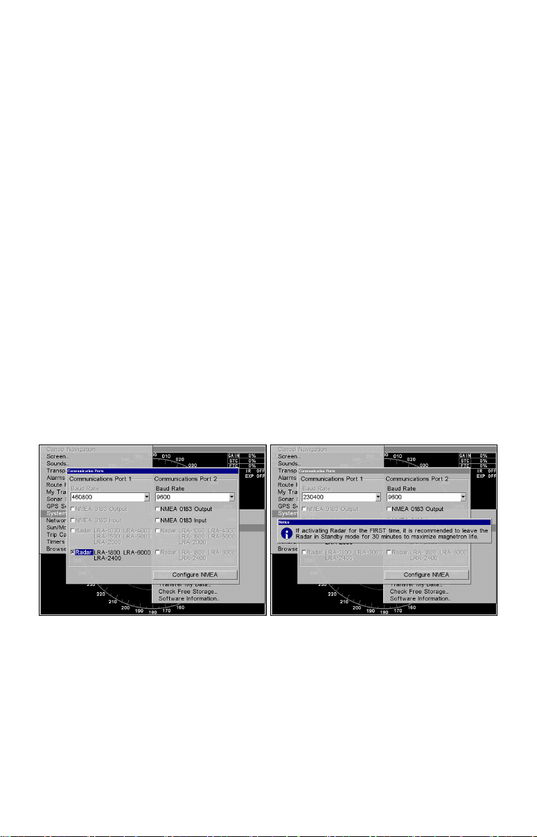
1. Press MENU|MENU, then use ↑ ↓ to SYSTEM SETUP and press ENT.
2. Highlight
3. Press ↓ to
checkbox. The Baud Rate automatically will switch to 230400 and a
Radar Notice will appear.
Communications Port menu (left). Radar Notice (right) prompting us-
ers to leave radar in Standby Mode for 30 minutes when activating ra-
Caution:
Leave the radar in Standby Mode for 30 minutes when activating it the first time. This will help maximize the life of the magnetron. After the radar has been activated the first time, ignore
the Radar Notice.
COMMUNICATIONS PORT and press ENT.
RADAR and press ENT, which will place an X in the radar
dar for the first time.
5
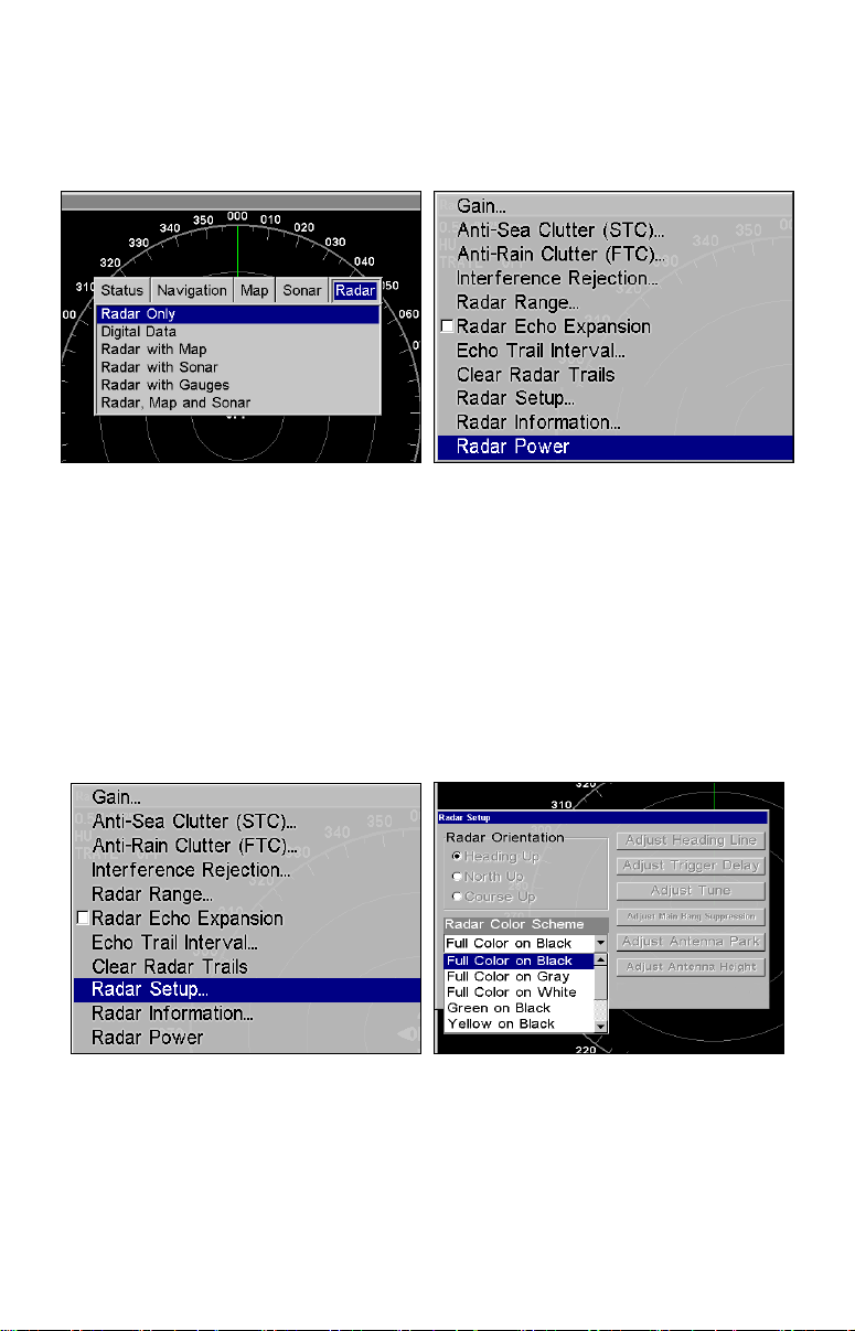
To access Radar Page:
1. Press PAGES, then use ← → to select the radar tab.
2. Press ↓ to select
RADAR ONLY then press EXIT.
Radar only highlighted on Radar Pages menu (left). Radar menu with
Radar Power selected (right).
3. Press MENU, then use ↑ ↓ to select RADAR POWER from the radar menu
and press
YES and press ENT. A warm-up countdown will commence that will vary
ENT. A confirmation message will appear. Press ← to select
depending on the model of radar you have.
4. After the countdown is finished, the unit will enter STANDBY mode.
5. Access the Radar Setup menu to make sure your radar display is set
to Heading Up and is set to a Full Color scheme. Press
RADAR SETUP and press ENT.
MENU, select
Radar Setup selected from Radar menu (left). Radar Setup menu with
Full Color on Black highlighted (right).
6. To set the radar to Heading Up, highlight HEADING UP and press ENT.
7. To display the radar images in full color, press ↓ to select
COLOR SCHEME and press ENT.
RADAR
6
8. Use ↑ ↓ to highlight one of the three full color options and press
Press
EXIT to return to the main page display.
ENT.
Auto Power-On
When the Auto Power-on feature is turned on, the radar will start
warming up every time the display unit is turned on. Access the Communications Port menu to turn on or turn off the Auto Power-on feature.
Caution:
If you do not plan to use your radar every time the display unit
is turned on, you need to turn off the Auto Power-On feature.
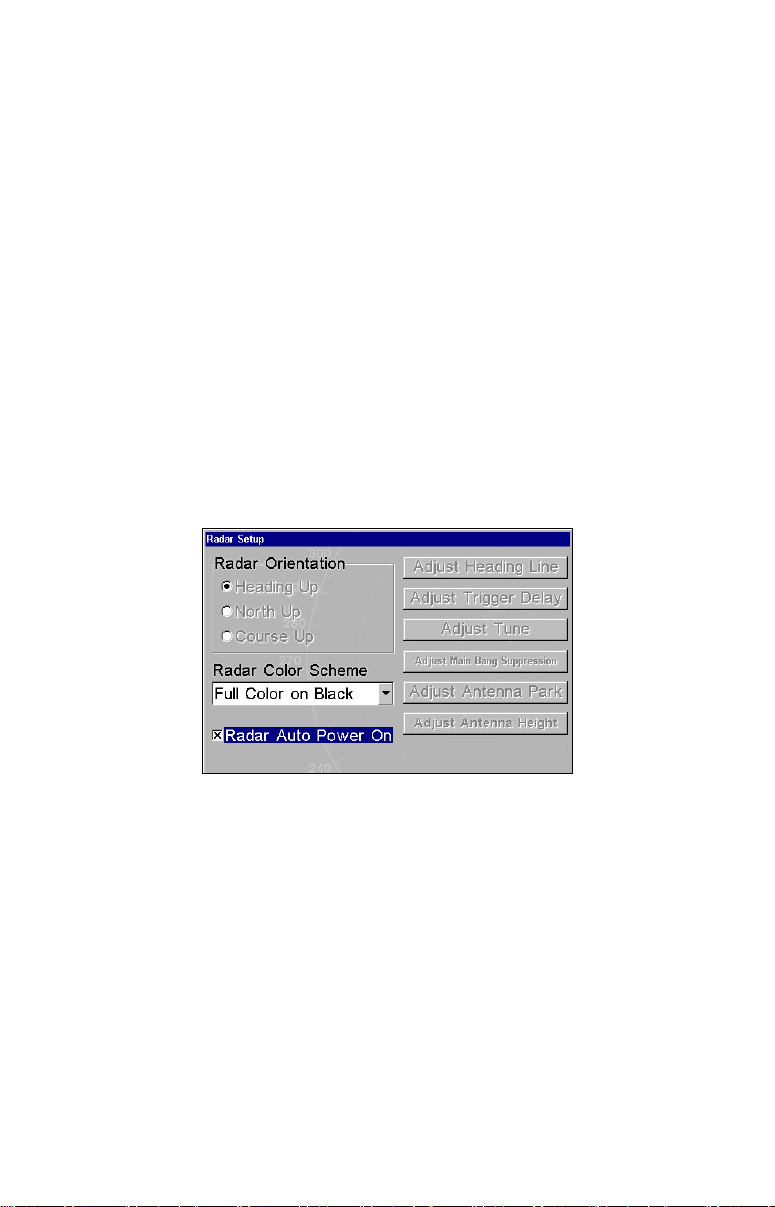
Turning on/off Auto Power-On:
1. From the Radar Page, press MENU, select RADAR SETUP and press ENT.
2. Highlight
RADAR AUTO POWER ON and press ENT, which will check (turn
on) or uncheck (turn off) the radar checkbox. Auto Power-On is active
when there is an "X" in the Radar Auto Power On checkbox.
3. Press
EXIT to return to the main radar display.
Communications Port menu with Auto Power-On feature turned on.
Radar Setup
The Radar Setup menu allows you to set up and adjust radar settings.
Most of the settings in the Radar Setup menu will only have to be set
once, but we recommend you check the settings periodically for general
maintenance.
NOTE:
Before starting radar setup, take your vessel out on open water
with fairly calm seas, like an open bay.
The two setup features we want to modify are Adjust Trigger Delay and
Adjust Heading Line.
7

We will set them up in that order, but before making any adjustments,
make sure the display is set to a range of 0.125 nautical miles and that
Gain, Anti-Sea Clutter (STC), Anti-Rain Clutter (FTC) and Trigger Delay all have been set to zero percent.
Trigger Delay Preparation
Range
1. To reset range to 0.125 nm, make sure you are on the Radar Only
page and press
MENU.
2. Use ↑ ↓ to select
Radar Range list. Press ↑ to select 0.125 nm and press
can set the range to 0.125 nm from the radar screen by using the
and
ZOUT keys.
Gain
RADAR RANGE and press ENT, which will call up the
ENT. You also
ZIN
1. To set Gain to zero, press MENU, select GAIN and press ENT.
2. Press ↓ until the Gain is set to zero percent. Press
EXIT. (Notice the
corresponding value in the upper right-hand corner of the screen.)
NOTE:
When adjusting Gain back to a useable level, increase the level until you see a light peppering on the display. Also remember, you will
have to adjust gain every time you change ranges.
Anti-Sea Clutter
1. To set Anti-Sea Clutter to zero, press MENU, select ANTI-SEA CLUTTER
(STC) and press ENT.
2. Press ↓ until the Anti-Sea Clutter is set to zero percent. Press
EXIT.
(Notice the corresponding value in the upper right-hand corner of the
screen.)
Anti-Rain Clutter
1. To set Anti-Rain Clutter to zero, press MENU, select ANTI-RAIN CLUTTER
(FTC) and press ENT.
2. Press ↓ until the Anti-Rain Clutter is set to zero percent. Press
EXIT.
(Notice the corresponding value in the upper right-hand corner of the
screen.)
Trigger Delay
1. To set Trigger Delay to zero, press MENU, select RADAR SETUP and
ENT.
press
8
2. Press →|↓ to
ADJUST TRIGGER DELAY and press ENT. That will launch
the Adjust Trigger Delay vertical scrollbar.
3. Press ↓ until Trigger Delay is set to zero percent. Press
EXIT.
Adjust Trigger Delay
This feature eliminates the time lag between real radar returns and the
time it takes data to be processed by the radar software, a common issue with all radars.
Caution:
If you have any doubt about your understanding of the Trigger
Delay feature, you should have it set up by a qualified radar
technician.
1. The radar should already be in STANDBY mode, so press
PWR for 2
seconds to switch the radar into transmission mode. A confirmation
message will appear, press ← to select
2. Press
MENU, select GAIN and press ENT. Press ↑ to increase the Gain
YES.
level to around 15%. One or two red rings with blue borders should be
visible on the screen, depending on the wattage of your radar antenna.
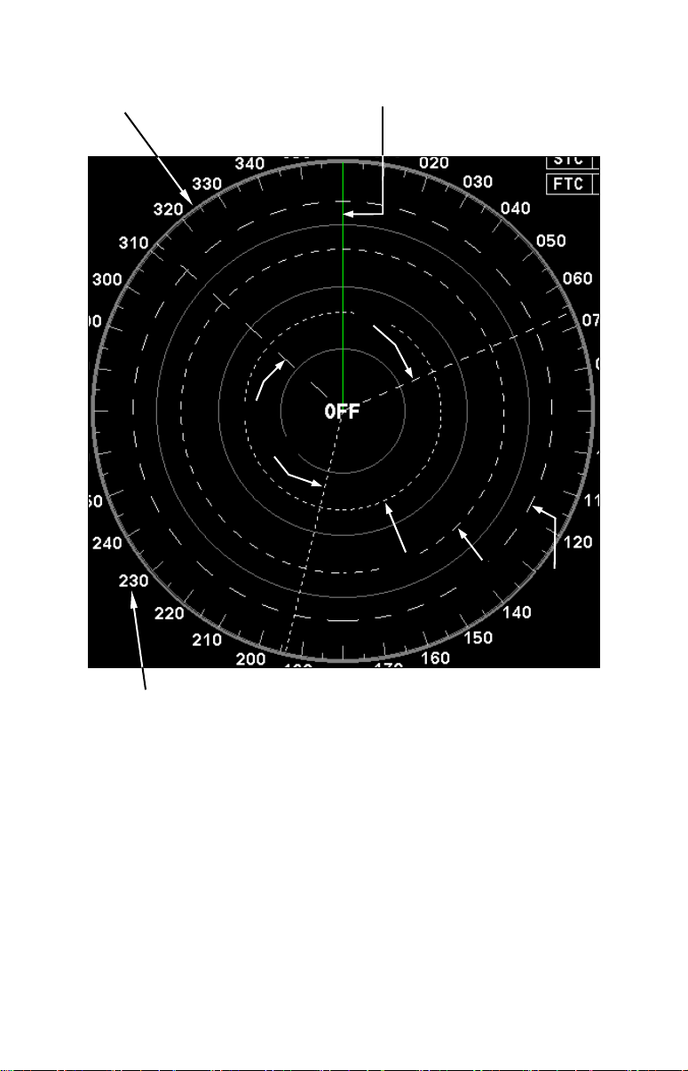
3. Press →|↓ to
ADJUST TRIGGER DELAY, then press ENT.
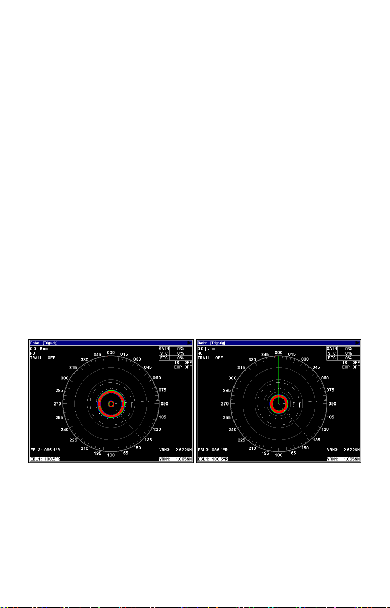
The 2 kW model, the LRA-1800, will have only one ring on the display.
The 4 kW model, the LRA-2400, will have two rings on the display. See
the following figures.
Before adjusting the Trigger Delay for 4 kW radars, two rings will be
shown on the screen (left). As Trigger Delay is increased, the larger
ring will start to get smaller. The small ring will disappear (right).
You may have to increase gain in the previous step if the rings are not
visible. Increase gain until you have solid red rings shown on the
screen, like in the preceding example. Increasing Gain too much can
cause the rings to be distorted.
9
 Loading...