

Page 1
www.lowrance.com
Pub. 988-0151-071
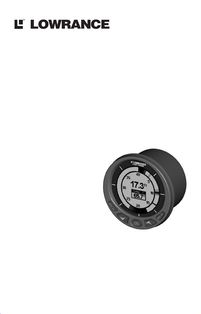
LCF-1440
LCD Flasher Sonar
Installation and Operation
Instructions
Page 2

Copyright © 2003 Lowrance Electronics, Inc.
All rights reserved.
Lowrance
®
is a registered trademark of Lowrance Electronics, Inc.
Marine-Tex is a trademark of Illinois Tool Works Inc.
Lowrance Electronics may find it necessary to change or end our
policies, regulations, and special offers at any time. We reserve the
right to do so without notice. All features and specifications subject to
change without notice. All screens in this manual are simulated.
For free owner's manuals and other information,
visit our web site:
www.lowrance.com
Lowrance Electronics Inc.
12000 E. Skelly Dr.
Tulsa, OK USA 74128-2486
Printed in USA.
Page 3

Table of Contents
Introduction ...............................................................................1
Capabilities and Specifications: LCF-1440.................................. 1
Installation Instructions.......................................................... 2
Preparation ...................................................................................2
Recommended Tools and Supplies ........................................... 2
Mounting the Unit ........................................................................ 2
Speaker...................................................................................... 3
Power Connections.................................................................... 4
Transducer ................................................................................ 4
Operation ....................................................................................5
Keyboard Basics............................................................................ 5
Memory.......................................................................................... 5
Menus ............................................................................................ 5
Display – Opening Screen ............................................................6
Range............................................................................................. 7
Sensitivity .....................................................................................7
Grayline
Alarms ........................................................................................... 9
Noise Reject and ASP
Display Adjustments .................................................................. 11
Sounds on/Off (Key Beep Menu) ................................................ 12
Simulator..................................................................................... 12
System Info (Unit Type Menu)................................................... 12
®
....................................................................................... 9
Fish Alarm................................................................................. 9
Depth Alarms .......................................................................... 10
(Advanced Signal Processing)............ 11
Temperature on/Off ................................................................ 11
Depth Units of Measure.......................................................... 11
Backlights................................................................................ 12
Display Contrast ..................................................................... 12
i
Page 4

Notes
ii
Page 5

Introduction
Thank you for buying a Lowrance LCF-1440 In-Dash Flasher! Your
unit is a high-quality flasher sonar designed for both professional and
novice fishermen. All Lowrance sonars have an automatic mode that
finds and displays the bottom, fish, underwater structure and more –
right out of the box. All you have to do is press the on (
However, if you want to fine-tune your unit, press the
sonar has several powerful features you can control by scrolling through
easy-to-use menus with the arrow and menu keys.
To get started with your Lowrance sonar, first read the installation
section. It contains instructions for mounting the sonar unit. If
necessary, also consult the accompanying transducer installation
instructions.
Following recommended installation practices will pay off in optimum
performance of your Lowrance sonar. Improper installation can cause
problems down the road, especially if the transducer is badly mounted.
After you've read the installation instructions, install the unit and
accessories. Then, read the rest of the manual. The more you know
about your sonar, the better it will work for you.
Take advantage of the Simulator feature. It allows you to practice
operating your sonar before you get it in the water. And when you finally
head for your favorite fishing hole, take this manual along for reference.
Capabilities and Specifications: LCF-1440
General
Case size: ...................... 3.8" diameter x 3.5" depth (9.7 cm diameter x
9.1 cm depth). Sealed, waterproof; suitable for
saltwater use.
Display:.........................Sunlight-viewable Film SuperTwist LCD. 2.5"
(6.3 cm) diameter viewing area.
Resolution:...................132 x 132 pixels (at x/y axis centerlines).
Backlighting:...............Multi-level white LED backlit screen.
Input power:................10 to 17 volts DC.
Current drain: ............140 mA lights off; 200 mA lights on full.
Back-up memory: .......Built-in memory stores sonar settings when
unit is turned off.
Sonar
Frequency:...................200 kHz.
Transducers: .................Choice of 20°, 200 kHz transducers with gray
connectors.
1
) key.
PWR
MENU UP
key. The
Page 6

Transmitter: ................800 watts peak-to-peak; 100 watts RMS.
Sonar sounding
depth capability: ........600 feet (180 meters). Actual capability depends
on transducer configuration and installation,
bottom composition and water conditions. All
sonar units typically read deeper in fresh water
than in salt water.
Depth display:.............Continuous digital readout.
Audible alarms: ..........Deep/shallow/fish.
Automatic ranging:....Yes.
Auto bottom track:.....Yes.
Surface water temp: ..Yes, when transducer with attached temp
sensor is used.
NOTICE!
The storage and operation temperature range for your unit is from
-4 degrees to +167 degrees Fahrenheit (-20 degrees to +75 degrees
Celsius). Extended storage or operation in temperatures higher or
lower than specified will damage the liquid crystal display in your
unit. This type of damage is not covered by the warranty. For more
information, contact the factory's Customer Service Department;
phone numbers are inside the manual's back cover.
Installation Instructions
Preparation
The design of the LCF-1440 allows convenient mounting in the dash of
your boat, or it can be mounted on any flat panel at least four inches in
diameter.
To mount the LCF-1440 in the dash, first make sure there is sufficient
clearance behind the panel in the desired location. Also, see that there is
adequate room to connect power and transducer cables. At least 3-1/2 inches
are needed behind the surface of the dash to clear all connectors and wiring.
Recommended Tools and supplies
Recommended tools for this job include: hole saw, drill, drill bit (for
starter hole). Required supplies for this job include: "U" bracket, lock
washers and wing nuts (included).
Mounting the Unit
Cut a 3-3/8 inch diameter mounting hole with a hole saw. A "U" bracket
is supplied to hold the sonar to the dash. Place it over the threaded
studs on the back of the unit and secure it with the lock washers and
nylon wing nuts provided with the unit.
2
Page 7

Secure unit to the dash using "U" bracket as shown.
y
(
)
The bracket is designed to secure the unit to a dash with a thickness of
2 mm. If your dash is thicker than 2 mm, the "U" bracket will be too
long. Simply place washers or spacers between the unit and the bracket
until you can tighten the wing nuts and secure the unit it place.
Once the unit is in place, you need to connect it to a power supply, to
the speaker (provided) and to the transducer. All of these elements are
described in the following paragraphs. Refer to the following
illustration as needed.
Speaker
Flasher unit
side view
Speaker cable
Black wires
Connect white wire
to "Lights" switch
on your boat's
instrument panel.
2-amp fuse
Red wires
Power/transducer cable
Pod transducer
LCF-1440 system components installed, including power connections.
Black wire
12 volt
batter
temp
sensor
3
Page 8

Speaker
Find a location for the speaker that is protected from the elements, but
still lets you hear it. The most common location is behind the dash. Make
sure to connect the speaker's wires to the same colored wires from the
unit – red to red (from the power source) and black to black (from the
speaker cable). See previous diagram for details. If the 1440's wires won't
reach the speaker, splice ordinary speaker wire to them.
Power Connections
The LCF-1440 works from a 12-volt battery system. For the best
results, attach the power cable directly to the boat's battery. You can
attach the power cable to an accessory or power buss, however you may
have problems with electrical interference. Therefore, it's safer to go
ahead and attach the power cable directly to the battery.
The power cable has two wires, red and black. Red is the positive lead,
black is negative or ground. Make sure to attach the in-line fuse holder
both to the red wire and directly to the power source. This will protect both
the unit and the power cable in the event of a short. It uses a 2-amp fuse.
CAUTION:
Do not use this product without a 2-amp fuse wired into the
power cable! Failure to use a 2-amp fuse will void your warranty.
The black wire is ground and should be connected to the negative side
of the battery or to a suitable ground buss.
This unit has reverse polarity protection. No damage will occur if the
power wires are reversed. However, the unit will not work until the
wires are attached correctly.
Transducer
This unit sometimes comes packaged with either a Skimmer
or podtype transducer. For transducer installation instructions, consult the
separate instruction sheet (part 988-0147-581 for Skimmer-type
transducers, part 988-0147-721 for pod-type).
Lowrance sells many different styles of transducers. If you do not have a
transducer installed, consult your local boat dealer or the Lowrance
service center for assistance selecting the proper transducer for your
boat. (Look inside the back cover of this manual for contact information.)
4
Page 9

Operation
Keyboard Basics
The unit sounds a tone when you press any key. This tells you the unit
has accepted a command. Numbers in the following image correspond
to the following key explanations.
1
2
The LCF-1440 Keyboard.
1. MENU UP (menu up) and MENU DN (menu down)
many features that are accessed with the menu keys. The
moves up or forward through the menus, the
down or backward. To see the first menu, simply press either
key. To see the other menus, press a
3
– This sonar unit has
MENU UP
MENU DOWN
key repeatedly to cycle
MENU
key moves
key
MENU
through the menu list.
2. UP and DOWN ARROWS
– Use these keys to adjust virtually every
feature and function on the sonar unit.
3. PWR/CLEAR (power and clear)
Hold the
key down for a countdown of five in order to turn the unit
PWR
– Use this key to turn the unit on and off.
off.
MEMORY
This unit has permanent memory that saves the following user settings
when power is turned off: Units of Measure, Fish Alarm, Temp Size,
Depth Size, Fish I.D. mode, Noise Reject mode, Display Contrast,
Shallow and Deep alarms. It does not require, nor does it use an internal
backup battery, so you never have to worry about replacement batteries.
MENUS
This unit uses menus to guide you through the various functions and
features. Menu names and settings appear in the manual text as small
capital letters like
S
ENSITIVITY
The menu keys access these features, allowing you to customize the unit to
your particular needs and water conditions. All you have to do to leave one
menu and enter another is press
the menus, simply press the
screen.
Menus change depending on the mode the unit is in. Messages may appear
in menu boxes or new menus can appear, depending on previous selections.
, which represents the Sensitivity menu.
repeatedly. If you ever get lost in
MENU
key. This clears the menus from the
PWR
5
Page 10

)
Menu
This screen shows a typical menu, the Sensitivity menu.
DISPLAY – Opening Screen
The lights flash for about 20 seconds when the unit is turned on. The
backlight menu appears on the screen. To turn the lights on, press
ARROW
seconds. If you don't want to wait, press
. If you don’t press a key, the menu will disappear after a few
to clear the menus.
PWR
When the sonar unit is first turned on and the backlight menu
disappears, the display screen shows the Flasher page. An image like
the one below will appear on the screen. A circular dial shows all
returning echoes at a high screen refresh rate. It uses the Grayline
feature (see "Grayline" below) to show weaker targets as shades of gray.
The bottom depth and temperature are also shown as digital displays in
the center of the circle. In the following figure, the screen shows a depth
range from 0 to 40 feet and the bottom depth is 17.3 feet, shown by the
digital sonar. The water temperature is 65.7° F.
Surface signal
Fish symbols
Depth range
at top of
depth scale
UP
Grayline
Digital depth
Flasher screen. The factory default settings have
automatic range and sensitivity turned on.
Water temp
(with optional
sensor
6
Page 11

If your transducer has a built-in temp sensor connected, the water
temperature will appear inside the circle. This temperature display can
be turned on and off. See the later entry on Temperature for off and on
instructions
RANGE
When turned on, the unit automatically adjusts the depth
range according to water conditions. When in auto range
mode, it always keeps the bottom displayed near the "Deep
End" of the Flasher. You can over-ride the automatic depth
range control and manually select a depth range.
To do this, press
ARROW
to select
MENU
M
ANUAL
until the
, then press
menu appears. Press the
R
ANGE
MENU UP
to display the
DOWN
R
ANGE SIZE
menu. Use the arrow keys to select a desired depth range.
When you're finished, press
to clear the menu from the
PWR
display.
This unit has the following depth ranges: 10, 20, 40, 80, 160,
320 and 640 feet.
SENSITIVITY
Sensitivity controls the unit's ability to pick up echoes. If you
want to see more detail, try increasing the sensitivity, a little
at a time. There are situations when too much clutter
appears on the screen. Decreasing the sensitivity can reduce
the clutter and show the strongest fish echoes, if fish are
present. As you change the sensitivity setting, you can see the
difference on the chart as it scrolls.
You can change the sensitivity level whether you are in Auto Sensitivity
mode or Manual Sensitivity mode. The adjustment method works the
same in both modes, but it gives you slightly different results.
Adjusting sensitivity in Auto Sensitivity Mode is similar to manually
adjusting a car's speed with the accelerator pedal while cruise control is
on. You can tell the car to run faster, but when you let off the gas the
cruise control automatically keeps you from running slower than the
minimum speed setting.
In your unit, auto mode will let you increase sensitivity to 100 percent, but
the unit will limit your minimum setting. This prevents you from turning
sensitivity down too low to allow automatic bottom tracking. When you
change the setting with auto turned on, the unit will continue to track the
7
Page 12

bottom and make minor adjustments to the sensitivity level, with a bias
toward the setting you selected.
Adjusting sensitivity in Manual Sensitivity Mode is similar to driving a
car without cruise control — you have complete manual control of the
car's speed. In your unit, manual mode allows you to set sensitivity at
100 percent (maximum) or zero percent (minimum.) Depending on
water and bottom conditions, the bottom signal may completely
disappear from the screen when you reduce sensitivity to about 45
percent or less!
Try adjusting sensitivity in both auto and manual modes to see how
they work.
These figures show results of different sensitivity levels. At left, a high
Sensitivity setting shows a display crowded with many return signals.
At right, a lower Sensitivity setting shows only a few strong returns.
To adjust sensitivity:
until the
MENU
Press
UP ARROW
to increase the sensitivity,
S
ENSITIVITY ADJUSTMENT
it. When it's set at the desired level, press
menu appears. Press
DOWN ARROW
to decrease
to clear the
PWR
menu.
The sensitivity percentage in use shows in this menu. As you
change the setting, echoes scrolling onto the screen will show the effects of
the change. If you reach the maximum or minimum sensitivity level, a tone
sounds alerting you to the limits.
NOTE:
If you want to change the sensitivity in Manual Mode,
first turn off Auto Sensitivity: press
S
ENSITIVITY AUTOMATIC/MANUAL
ARROW
to select
M
ANUAL
menu appears. Press
, then press
PWR
to clear the menu.
MENU
until the
DOWN
To adjust the sensitivity, follow the same steps used for
adjusting sensitivity in auto mode above.
8
Page 13

GRAYLINE
®
Grayline lets you distinguish between strong and weak
echoes. It "paints" gray on targets that are stronger than a
preset value. This allows you to tell the difference between a
hard and soft bottom. For example, a soft, muddy or weedy
bottom returns a weaker signal which is shown with a
narrow or no gray line. A hard bottom returns a strong
signal which causes a wide gray line.
If you have two signals of equal size, one with gray and the other
without, then the target with gray is the stronger signal. This helps
distinguish weeds from trees on the bottom, or fish from structure.
Grayline is adjustable. The factory default for this unit is 72 percent.
Since Grayline shows the difference between strong and weak signals,
adjusting the sensitivity may also require a different Grayline level.
The level chosen by the sonar unit at power on is usually adequate for
most conditions. Experiment with your unit to find the Grayline setting
that's best for you.
To change the Grayline level, press
Press
UP ARROW
to increase the level or press
MENU
until the
G
menu appears.
RAYLINE
DOWN ARROW
to
decrease it. The percentage of Grayline in use shows in this menu.
Echoes scrolling onto the screen will also show the effects of the
Grayline change. If you reach the maximum or minimum level, a tone
sounds alerting you to the limits. Press
to clear the menu.
PWR
ALARMS
The sonar unit has three different types of alarms: fish, shallow and deep.
Fish Alarm
The Fish Alarm sounds a tone when a fish symbol appears on
the screen. The default setting is on, but the Fish I.D. feature
must be turned on for fish alarms to work.
To turn Fish I.D. on, press
press
select
appears. Press
until the
MENU
, then press
O
N
UP ARROW
F
ISH ALARM
.
PWR
to select
menu appears. Press
To turn off the fish alarm without turning off fish symbols, press
DOWN
until
F
ISH ALARM
press
to clear the menu. Repeat the above steps to turn the alarm
PWR
back on, but press
appears. Press
UP ARROW
to select
DOWN ARROW
O
9
until the
MENU
, then press
O
N
before clearing the menu.
N
F
ISH
PWR
UP ARROW
to select
ID
O
menu
. Then,
MENU
, then
FF
to
Page 14

Depth Alarms
The depth alarms are triggered only by the bottom signal. No other
echoes will activate these alarms. The depth alarms consist of a shallow
and a deep alarm. The shallow alarm sounds an alarm tone when the
bottom goes shallower than the alarm's setting. The deep alarm sounds
a tone when the bottom goes deeper than its setting. Both alarms adjust
the same way, although through different menus.
Shallow Alarm
To set the shallow alarm depth, press
repeatedly until
S
HALLOW ALARM
appears.
MENU DOWN
Press
UP ARROW
setting or press
to increase the shallow alarm's depth
DOWN ARROW
to decrease it. The number in
the shallow alarm’s menu box shows the current shallow
alarm setting. When the number reaches the desired setting, press
PWR
to clear the menu. When the bottom depth goes shallower than the
alarm’s setting, an alarm tone sounds and a message box appears on
the screen.
Press
to silence the alarm. This turns the alarm sound off until
PWR
the shallow alarm is triggered again.
To turn the alarm off, press
appears. Press
A
LARM
then press
Deep Alarm
to clear the menu.
PWR
DOWN ARROW
To set the deep alarm depth, press
until
D
EEP ALARM
Press
UP ARROW
or press
DOWN ARROW
appears.
to increase the deep alarm's depth setting
MENU DOWN
until the words
to decrease it. The number in the
repeatedly until
O
FF FEET
MENU DOWN
repeatedly
S
HALLOW
appear,
deep alarm’s menu box shows the current deep alarm
setting. When the number reaches the desired setting, press
PWR
to
clear the menu. When the bottom depth goes deeper than the alarm’s
setting, an alarm tone sounds and a message box appears on the
screen.
Press
to silence the alarm. This turns the alarm sound off until
PWR
the deep alarm is triggered again.
To turn the alarm off, press
appears. Press
press
PWR
DOWN ARROW
to clear the menu.
MENU DOWN
until the words
10
repeatedly until
O
FF FEET
appear, then
D
EEP ALARM
Page 15

NOISE REJECT and ASP (Advanced Signal Processing)
The ASP (Advanced Signal Processing) feature is a noise
rejection system built into the sonar unit. It constantly
evaluates the effects of boat speed, water conditions and
electrical interference and automatically gives you the best
display possible under most conditions.
ASP is an effective tool in combating noise. In sonar terms, noise is any
undesired signal. It is caused by electrical and mechanical sources such
as bilge pumps, engine ignition systems and wiring, air bubbles passing
over the face of the transducer, even vibration from the engine. In all
cases, noise can produce unwanted marks on the display.
The ASP noise rejection feature is especially useful because it typically
lets you operate the boat at all speeds without adjusting the sensitivity
or other controls.
The ASP feature has three settings — Off, Low and High. When first
turned on, noise rejection is set on low. If you have high noise levels, try
using the high ASP setting. However, if you are having trouble with
noise, we suggest that you take steps to find the interference source and
fix it, rather than continually using the unit with the high ASP setting.
There are times when you may want to turn ASP off. This allows you to
view all incoming echoes before they are processed by the ASP feature.
To change the ASP setting, press
MENU DOWN
until
N
OISE REJECT
appears. Use the up and down arrow keys to select the desired setting,
then press
to clear the menu.
PWR
DISPLAY ADJUSTMENTS
TEMPERATURE ON/OFF
This unit is capable of displaying surface water temperature when it is
connected to a transducer with built-in temp sensor. (For accessory
ordering information, look inside the back cover of this manual.)
If you have a temp sensor connected and wish to see the water temp,
repeatedly until the
MENU
press
to turn the temperature display on or the
DEPTH UNITS OF MEASURE
This unit can show the depth in feet or meters.
To change the depth units of measure, press
until the
menu appears. Use the arrow keys to select
U
NITS
the desired unit of measure, then press the
the menu.
menu appears. Press
T
EMP
DOWN ARROW
11
UP ARROW
to turn it off.
MENU DOWN
key to clear
PWR
Page 16

BACKLIGHTS
The display is backlit for night use. To turn the backlight on
or off, press
appears. Press
ARROW
to turn it off.
DISPLAY CONTRAST
The unit’s display contrast is adjustable to suit different
lighting conditions. This will help you see the screen from
different angles or at various times of the day. The default
setting is min (minimum) percent.
repeatedly until the
MENU
UP ARROW
to turn the light on or the
B
ACK LIGHT
menu
DOWN
C
ONTRAST
ARROW
To adjust the contrast, press
MENU DOWN
menu appears. To decrease screen contrast, press the
key. Press the
UP ARROW
key to increase screen contrast. The
until the
D
ISPLAY
DOWN
bar graph in the Contrast menu box shows a graph of the contrast. The
screen will also show the effects of the change. If you reach the
maximum or minimum level, a tone sounds alerting you to the limits.
Press the
key to clear the menu.
PWR
SOUNDS ON/OFF (Key Beep Menu)
This unit sounds a tone whenever a key is pressed or an alarm goes off.
To disable sounds, press
appears. Press
UP ARROW
repeatedly until the
MENU
to turn sounds on or the
K
EY BEEP
DOWN ARROW
menu
to
turn them off.
SIMULATOR
This unit has a built-in simulator that shows a simulated
bottom signal with fish signals. This lets you practice with
the unit as if you were on the water; all features and
functions of the unit are usable. A message appears
occasionally to remind you that the simulator is on.
To use the simulator, press
menu appears. Press
MENU DOWN
UP ARROW
to turn it on, and press
the menu. Repeat the above steps to turn it off, or you can simply turn
the unit off and back on again.
repeatedly until the
PWR
S
IMULATOR
to clear
SYSTEM INFO (Unit Type Menu)
To show the operating software system information, press
MENU DOWN
until the
clear the screen.
U
menu appears. Press
NIT INFO
12
PWR
to
Page 17

LOWRANCE ELECTRONICS
FULL ONE-YEAR WARRANTY
"We," "our," or "us" refers to LOWRANCE ELECTRONICS, INC., the manufacturer of
this product. "You" or "your" refers to the first person who purchases this product as a
consumer item for personal, family or household use.
We warrant this product against defects or malfunctions in materials and workmanship,
and against failure to conform to this product's written specifications, all for one (1) year
from the date of original purchase by you. WE MAKE NO OTHER EXPRESS
WARRANTY OR REPRESENTATION OF ANY KIND WHATSOEVER CONCERNING
THIS PRODUCT. Your remedies under this warranty will be available so long as you can
show in a reasonable manner that any defect or malfunction in materials or
workmanship, or any non-conformity with the product's written specifications, occurred
within one year from the date of your original purchase, which must be substantiated by
a dated sales receipt or sales slip. Any such defect, malfunction, or non-conformity which
occurs within one year from your original purchase date will either be repaired without
charge or be replaced with a new product identical or reasonably equivalent to this
product, at our option, within a reasonable time after our receipt of the product. If such
defect, malfunction, or non-conformity remains after a reasonable number of attempts to
repair by us, you may elect to obtain without charge a replacement of the product or a
refund for the product. THIS REPAIR, OR REPLACEMENT OR REFUND (AS JUST
DESCRIBED) IS THE EXCLUSIVE REMEDY AVAILABLE TO YOU AGAINST US FOR
ANY DEFECT, MALFUNCTION, OR NON-CONFORMITY CONCERNING THE
PRODUCT OR FOR ANY LOSS OR DAMAGE RESULTING FROM ANY OTHER
CAUSE WHATSOEVER. WE WILL NOT UNDER ANY CIRCUMSTANCES BE LIABLE
TO ANYONE FOR ANY SPECIAL, CONSEQUENTIAL, INCIDENTAL, OR OTHER
INDIRECT DAMAGE OF ANY KIND.
Some states do not allow the exclusion or limitation of incidental or consequential
damages, so the above limitations or exclusions may not apply to you.
This warranty does NOT apply in the following circumstances: (1) when the product has
been serviced or repaired by anyone other than us; (2) when the product has been
connected, installed, combined, altered, adjusted, or handled in a manner other than
according to the instructions furnished with the product; (3) when any serial number has
been effaced, altered, or removed; or (4) when any defect, problem, loss, or damage has
resulted from any accident, misuse, negligence, or carelessness, or from any failure to
provide reasonable and necessary maintenance in accordance with the instructions of the
owner's manual for the product.
We reserve the right to make changes or improvements in our products from time to time
without incurring the obligation to install such improvements or changes on equipment
or items previously manufactured.
This warranty gives you specific legal rights and you may also have other rights which
may vary from state to state.
REMINDER: You must retain the sales slip or sales receipt proving the date of your
original purchase in case warranty service is ever required.
LOWRANCE ELECTRONICS
12000 E. SKELLY DRIVE, TULSA, OK 74128
(800) 324-1356
13
Page 18

How to Obtain Service…
…in the USA:
We back your investment in quality products with quick, expert service
and genuine Lowrance parts. If you're in the United States and you
have technical, return or repair questions, please contact the Factory
Customer Service Department. Before any product can be returned, you
must call customer service to determine if a return is necessary. Many
times, customer service can resolve your problem over the phone
without sending your product to the factory. To call us, use the
following toll-free number:
800-324-1356
8 a.m. to 5 p.m. Central Standard Time, M-F
Lowrance Electronics may find it necessary to change or end our
shipping policies, regulations, and special offers at any time. We reserve
the right to do so without notice.
…in Canada:
If you're in Canada and you have technical, return or repair questions,
please contact the Factory Customer Service Department. Before any
product can be returned, you must call customer service to determine if
a return is necessary. Many times, customer service can resolve your
problem over the phone without sending your product to the factory. To
call us, use the following toll-free number:
800-661-3983
905-629-1614 (not toll-free)
8 a.m. to 5 p.m. Central Standard Time, M-F
…outside Canada and the USA:
If you have technical, return or repair questions, contact the dealer in
the country where you purchased your unit. To locate a dealer near
you, visit our web site, www.lowrance.com and look for the Dealer
Locator.
14
Page 19

Accessory Ordering Information
for all countries
To order Lowrance accessories such as power cables or transducers,
please contact:
1) Your local marine dealer or consumer electronics store. Most quality
dealers that handle marine electronic equipment or other consumer
electronics should be able to assist you with these items.
To locate a Lowrance dealer near you, visit our web site,
www.lowrance.com and look for the Dealer Locator. Or, you can consult
your telephone directory for listings.
2) U.S. customers: LEI Extras Inc., PO Box 129, Catoosa, OK 74015-0129
Call 1-800-324-0045 or visit our web site www.lei-extras.com.
3) Canadian customers can write:
Lowrance/Eagle Canada, 919 Matheson Blvd. E. Mississauga, Ontario
L4W2R7 or fax 905-629-3118.
Shipping Information
If it becomes necessary to send a product for repair or replacement, you
must first receive a return authorization number from Customer
Service. Products shipped without a return authorization will not be
accepted. When shipping, we recommend you do the following:
1. Please do not ship the knobs or mounting bracket with your unit.
2. If you are sending a check for repair, please place your check in an
envelope and tape it to the unit.
3. For proper testing, include a brief note with the product describing
the problem. Be sure to include your name, return shipping address
and a daytime telephone number. An e-mail address is optional but
useful.
4. Pack the unit in a suitable size box with packing material to prevent
any damage during shipping.
5. Write the Return Authorization (RA) number on the outside of the
box underneath your return address.
6. For your security, you may want to insure the package through your
shipping courier. Lowrance does not assume responsibility for goods
lost or damaged in transit.
Page 20

Visit our web site:
Lowrance Pub. 988-0151-071 © Copyright 2003
All Rights Reserved
Printed in USA 041703 Lowrance Electronics, Inc.
 Loading...