

Pub. 988-0160-001
www.lowrance.com
Mapping GPS & MP3 Player
Operation Instructions

Copyright © 2006 Lowrance Electronics, Inc.
All rights reserved.
No part of this manual may be copied, reproduced, republished,
transmitted or distributed for any purpose, without prior written
consent of Lowrance. Any unauthorized commercial distribution
of this manual is strictly prohibited.
iFINDER
and Lowrance® are registered trademarks of Lowrance
Electronics, Inc. Expeditionc is a trademark of Lowrance Electronics,
Inc. MapCreate, FreedomMaps and NauticPath are trademarks
of LEI. Fishing Hot Spots
is a registered trademark of Fishing Hot
Spots Inc. LakeMaster
and ProMaps are trademarks or registered
trademarks of Waypoint Technologies, Inc. Navionics
is a registered
trademark of Navionics, Inc. DURACELL
is a registered trademark of
Duracell, Inc. RAYOVAC
is a registered trademark of Rayovac
Corporation. Energizer
and e
2
are registered trademarks of Energizer
Holdings, Inc.
Points of Interest Data in this unit are by infoUSA,
copyright 2001-2005, All Rights Reserved. infoUSA is a
trademark of infoUSA, Inc.
eXitSource Database, copyright 2001-2005 Zenrin Co.
Ltd. Exit Authority and eXitSource are trademarks of
Zenrin Co. Ltd.
Lowrance Electronics may find it necessary to change or end our
policies, regulations and special offers at any time. We reserve the right
to do so without notice. All features and specifications subject to change
without notice. All screens in this manual are simulated. This manual
was written for software version 1.0.0.
For free owner's manuals and the most current information on
this product, its operation and accessories,
visit our web site:
www.lowrance.com
Lowrance Electronics Inc.
12000 E. Skelly Dr.
Tulsa, OK USA 74128-2486
Printed in USA.

i
Table of Contents
Section 1: Read Me First!......................................................... 1
Specifications: ............................................................................... 2
How the iFINDER Expeditionc Works ..................................... 4
Introduction to GPS, WAAS and EGNOS ................................... 6
How to use this manual: typographical conventions .................. 8
Arrow Keys................................................................................ 8
Keyboard ................................................................................... 8
Menu Commands ...................................................................... 8
Instructions = Menu Sequences ............................................... 9
Section 2: Installation & Accessories..................................11
Power........................................................................................... 11
Batteries...................................................................................... 11
Battery Installation ................................................................ 12
Cigarette Lighter Power Adapter .............................................. 13
NMEA Cable Connections .......................................................... 13
MMC or SD Memory Card Installation ..................................... 14
Mapping Resources..................................................................... 15
External Antenna ....................................................................... 16
R-A-M
Bracket Mounting Systems .......................................... 17
Other Accessories........................................................................ 18
Section 3: Easy Mode Operation .......................................... 19
Keypad......................................................................................... 19
Power/lights on and off ............................................................... 20
Main Menu .................................................................................. 20
Pages ........................................................................................... 21
Satellite Status Page .............................................................. 21
Navigation Page...................................................................... 22
Map Page................................................................................. 24
Easy Mode Quick Reference ................................................. 28
Find Your Current Position........................................................ 29
Selecting Any Map Item with the Cursor.................................. 30
Searching..................................................................................... 30
Set Home Waypoint .................................................................... 32
Set Man Overboard (MOB) Waypoint........................................ 33
Navigate Back to MOB Waypoint .......................................... 33
Navigate to Cursor Position on Map.......................................... 34
Navigate to a Point of Interest................................................... 35
Creating and Saving a Trail....................................................... 35
Displaying a Saved Trail ........................................................ 36
Navigating or Backtracking a Trail ........................................... 36
Visual Back Trailing ............................................................... 36
Navigate a Back Trail............................................................. 36

ii
Clearing a Trail....................................................................... 38
Transfer Custom Maps and GPS Data Files ............................. 38
Switch to Advanced Mode........................................................... 40
Section 4: Advanced Mode Operation.................................41
Keypad......................................................................................... 41
Power/lights on and off ............................................................... 42
Main Menu .................................................................................. 42
Pages ........................................................................................... 43
Satellite Status Page .............................................................. 43
Status Menu ............................................................................ 44
Digital Data Page.................................................................... 44
Digital Data Menu .................................................................. 45
Navigation Page...................................................................... 45
Navigation Menu .................................................................... 46
Music Mode Page .................................................................... 46
Map Page................................................................................. 47
Map Menu ............................................................................... 48
Find Distance to Another Location ............................................ 48
Find Distance from Point to Point ............................................. 48
Find Your Current Position........................................................ 49
Icons............................................................................................. 49
Create Icon on Map............................................................. 49
Create Icon at Current Position ......................................... 50
Delete an Icon ......................................................................... 50
Load GPS Data Files from an MMC .......................................... 50
Navigate ...................................................................................... 51
Navigate Back Home .............................................................. 51
Navigate Back to Man Overboard Waypoint......................... 51
Cancel Navigation................................................................... 52
Navigate a Route..................................................................... 52
Navigate to Cursor Position on Map...................................... 52
Navigate to Point of Interest (POI) ........................................ 52
Navigate to a Waypoint .......................................................... 52
Navigate a Trail ...................................................................... 53
Routes.......................................................................................... 54
Create and Save a Route ........................................................ 54
PC-created Routes............................................................... 54
Delete a Route ......................................................................... 56
Save GPS Data Files to an MMC............................................... 56
Searching..................................................................................... 56
Trails ........................................................................................... 58
Create and Save a Trail.......................................................... 58
Delete a Trail .......................................................................... 58

iii
Edit a Trail Name ................................................................... 59
Edit a Trail Color .................................................................... 59
Edit a Trail Pattern ................................................................ 59
Transfer Custom Maps and GPS Data Files ............................. 59
Utilities........................................................................................ 60
Sun/Moon Calculation............................................................. 60
Trip Calculator........................................................................ 61
Alarm Clock............................................................................. 61
Down Timer............................................................................. 61
Up Timer ................................................................................. 61
Trip Calculator............................................................................ 61
Trip Active............................................................................... 61
Reset Trip ................................................................................ 61
Threshold................................................................................. 61
Calculated Data ...................................................................... 61
Speed, Average Speed and Max Speed............................... 62
Trip Time and Trip Distance .............................................. 62
Weather Prediction (barometer) ................................................ 62
Interpreting Weather Information......................................... 63
Sleep Mode .............................................................................. 65
Waypoints.................................................................................... 66
Create Waypoint on Map .................................................... 66
Create Waypoint at Current Position ................................ 66
Create a Man Overboard Waypoint ................................... 66
Create a Waypoint by Average Position ............................ 66
Create a Waypoint by Projecting a Position ...................... 67
Select a Waypoint ................................................................... 67
Delete a Waypoint................................................................... 67
Edit a Waypoint ...................................................................... 68
Waypoint Name................................................................... 68
Waypoint Symbol ................................................................ 68
Waypoint Position ............................................................... 68
Waypoint Altitude............................................................... 68
Waypoint Audio Note.......................................................... 69
Section 5: System & GPS Setup Options ............................71
Alarms ......................................................................................... 71
Auto Satellite Search.................................................................. 72
Check MMC Files and Storage Space........................................ 73
Com Port Configuration ............................................................. 73
Configure NMEA ........................................................................ 74
Use WAAS/EGNOS..................................................................... 75
Coordinate System...................................................................... 75
Map Fix.................................................................................... 77

iv
Customize Page Displays ........................................................... 78
Customize Digital Data Page ................................................. 78
Customize Navigation Page ................................................... 79
Customize Map Page .............................................................. 79
External Passive Antenna ...................................................... 79
GPS Simulator ............................................................................ 80
Map Auto Zoom........................................................................... 81
Scouting....................................................................................... 81
Map Data..................................................................................... 83
Popup Map Information.......................................................... 83
Draw Map Boundaries............................................................ 83
Fill Water with White............................................................. 83
Map Overlays (Range Rings, Lat/Long Grid) ........................ 84
Map Datum Selection ................................................................. 84
Map Detail Category Selection................................................... 85
Map Orientation ......................................................................... 86
NauticPath USA Marine Charts............................................. 87
Nautical Chart Notes.............................................................. 87
Port Information ..................................................................... 88
Tidal Current Information ..................................................... 89
Tide Information ..................................................................... 91
Navionics
Charts....................................................................... 92
Pop-up Help................................................................................. 93
Reset Options .............................................................................. 94
Screen Contrast and Brightness ................................................ 94
Set Language .............................................................................. 96
Set Local Time ............................................................................ 96
Software Version Information.................................................... 97
Sounds and Alarm Sound Styles................................................ 98
Track Smoothing......................................................................... 99
Trail Options ............................................................................... 99
General Trail Options ....................................................... 100
Update Trail Option.............................................................. 100
Update Trail Criteria............................................................ 101
Trail Update Rate ................................................................. 101
Specific Trail Options........................................................ 101
Delete Trail ........................................................................... 101
New Trail............................................................................... 101
Trail Visible/Invisible and Other Trail Options .................. 102
Units of Measure....................................................................... 102
Section 6: Searching ............................................................. 105
Selected Item............................................................................. 106
Destination................................................................................ 106

v
Recent Finds ............................................................................. 107
Current Route ........................................................................... 107
Find Addresses.......................................................................... 108
Find Home Waypoint................................................................ 110
Find Interstate Highway Exits ................................................ 110
Find Map Places or Points of Interest (POI) ........................... 111
Find Streets or Intersections.................................................... 113
Find Waypoints (Advanced Mode only) ................................... 116
Section 7: Music Mode .......................................................... 119
The Music Mode Display .......................................................... 119
Play Control Buttons ............................................................ 120
Launch Music Browser ......................................................... 120
Music Mode Practice Run ...................................................122
Play Lists................................................................................... 123
Getting Music onto the iFINDER ........................................ 123
The Music Menu ....................................................................... 123
Use Indoors ............................................................................... 124
Sounds Menu............................................................................. 124
Shuffle (On/Off)..................................................................... 124
Repeat (On/Off) ..................................................................... 124
Section 8: Supplemental Material .....................................125

vi
WARNING!
A CAREFUL NAVIGATOR NEVER RELIES ON ONLY ONE METHOD
TO OBTAIN POSITION INFORMATION.
CAUTION
When showing navigation data to a position (waypoint), a GPS unit will show
the shortest, most direct path to the waypoint. It provides navigation data to the
waypoint regardless of obstructions. Therefore, the prudent navigator will not
only take advantage of all available navigation tools when traveling to a waypoint, but will also visually check to make sure a clear, safe path to the waypoint
is always available.
WARNING!
When a GPS unit is used in a vehicle, the vehicle operator is solely responsible for operating the vehicle in a safe manner. Vehicle operators
must maintain full surveillance of all pertinent driving, boating or flying conditions at all times. An accident or collision resulting in damage
to property, personal injury or death could occur if the operator of a
GPS-equipped vehicle fails to pay full attention to travel conditions and
vehicle operation while the vehicle is in motion.

1
Section 1: Read Me First!
How this manual can get you out on the road, fast!
Welcome to the exciting world of GPS satellite navigation! We know
you're anxious to begin finding your way with this hand-held technology, but we have a favor to ask. Before you grab the batteries and head
outside, please give us a moment or two to explain how our manual can
help you get the best performance from this remarkable little GPS unit.
First, we want to thank you for buying an iFINDER
Expeditionc.
Whether you're a first-time user or a professional navigator, you'll discover that the iFINDER is a true pocket-sized, full-featured mapping
GPS receiver. When you team an iFINDER with one of our specialized
maps or our custom mapping software MapCreate 6, you have an incredible combination. No other consumer GPS mapping system on the
market offers so much information and so many features in one package.
Our goal for this book is to get you on the road or out to the woods and
water fast, with a minimum of fuss. Like you, we'd rather spend more
time traveling and less time reading the manual!
So, we designed our book so that you don't have to read the whole thing
from front to back for the information you want. At the start (or end) of
each segment, we'll tell you what content is coming up next. If it's a
concept you're already familiar with, we'll show you how and where to
skip ahead for the next important topic. We've also made it easy to look
up any tips you may need from time to time. Here's how:
The manual is organized into seven sections. This first section is an
introduction to Lowrance GPS. It tells you the basics you need to know
before you can make the unit look around and tell you where you are.
Section 2 will help you get the batteries and MultiMedia Card (MMC)
correctly installed in your iFINDER. We'll also tell you about some of
the accessories available for your unit.
Section 3 is the heart of our book, Easy Mode Operation. It will introduce you to the basic GPS functions. We lead off this section with a onepage Easy Mode Quick Reference. (If you've already figured out
how to load the batteries yourself, and you just can't wait any
longer, turn to the Quick Reference on page 28 and head outside with your iFINDER!)

2
The rest of Section 3 contains short, easy-to-scan lessons that follow
one another in chronological order. They're all you'll need to know to
find your way on the water or in the wilderness quickly.
Easy Mode operation will meet the navigation needs of many users.
But, after you've learned the basics (or if you already have some GPS
experience), you may want to try out some of the iFINDER's many advanced navigation features. That brings us to Section 4, Advanced
Mode Operation. After we introduce the Advanced Mode menus and
submenus, this section contains the rest of the iFINDER's command
functions, organized in alphabetical order.
When you come to a GPS menu command on the iFINDER screen, you can
look it up in the manual by skimming over the table of contents, flipping
through Section 3 or scanning through the command portion of Section 4.
The iFINDER is ready to use right out of the box, but you can fine tune
and customize its operation with dozens of options. We describe how to
use general system options along with GPS options in Section 5, System
Setup and GPS Setup Options. This section covers both Easy Mode and
Advanced Mode options.
In Section 6, we go into more detail on one of the iFINDER's most remarkable capabilities — Searching. We'll introduce a couple of search
examples in both the Easy and Advanced mode sections, but there are
so many map items you can search for, we had to give this function its
own section in the manual! For example, did you know the iFINDER
can look up business phone numbers, functioning as a virtual Yellow
Pages? We’ll show you how in Section 6.
Finally, in Section 7, we offer Supplemental Material, including a list of
the GPS datums used, warranties, and customer service information.
Now, if you are into the fine details, glance over the next segment on
specifications to see how much GPS power you hold in your hand. It's
important to us (and our power users), but if you don't care how many
waypoints the iFINDER can store or how long the batteries last, skip
ahead to important information on how the iFINDER works, on page 4.
Specifications: iFINDER Expeditionc
General
Display:............................ 2.83" (7.18 cm) diagonal color TFT display.
Resolution:...................... 320 pixel x 240 pixel resolution; 256 color
screen
Backlighting:.................. White LED screen backlighting for night and
low-light viewing.

3
Input power:......................3 volts DC (two 1.5v AA batteries); operates up
to 12 hours on batteries when using one-second
position updates (longer update rates further
extend battery life, but will reduce GPS accuracy). Cigarette lighter adapter included.
Case size:......................... 5.6" H x 2.5" W x 0.9" D (142 x 65 x 25 mm);
water resistant to IPX-7 standards.
Weight:..................................8.48 ounces (242 grams) with alkaline batteries.
GPS
Receiver: ......................... Internal, 16 parallel channel
GPS+WAAS+EGNOS; external active or passive
antennas optional.
Active Antenna
Voltage:............................ 3 volts DC.
Recording: ...................... Removable MMC or SD memory cards for
recording GPS trip details, displaying custom maps, adding audio notes to waypoints,
upgrading operating system software and
transferring trip data to personal computer
without a slow serial connection.
MMC slots: ...................... One, inside battery compartment. Accepts
non-proprietary MMC or SD memory cards.
Background map:.......... Built-in custom, detailed Lowrance map.
Contains: low-detail maps of the whole world
(containing cities, major lakes, major rivers,
political boundaries); and medium-detail
maps of the United States (containing all incorporated cities; Interstate, U.S. and state
highways; Interstate highway exits and exit
services information; large- and mediumsized lakes and streams.)
Custom mapping: .......... Accepts custom, higher-detail MapCreate 6
mapping on memory cards, with searchable
Points-of Interest database of hotels, restaurants, shopping, services and more. NauticPath USA, Fishing HotSpots
Elite,
FreedomMaps, LakeMaster
ProMaps and
Navionics
charts are optional.
Mapping memory: ......... Up to 1 GB on one MMC (MultiMedia Card)
or SD (Secure Digital Card.)

4
Position updates: .......... Up to every second.
Position points: ............. 1,000 waypoints; 1,000 event marker icons.
Graphic symbols for
waypoints or event
marker icons: ................. 42.
Routes:............................. 100; up to 100 waypoints per route.
Plot Trails: ...................... 99 savable; up to 9,999 points per trail.
Man Overboard:............. MOB feature precisely marks man overboard
location with special icon, then automatically
displays navigation data to that position.
Audible alarms: ............. Arrival/off-course/destination passed/anchor.
Com Port: ........................ One serial communications port, NMEA 0183
version 2.0 compatible. Allows exchange of
position data with another device, such as an
autopilot or personal computer. Optional
combination serial/power cable available.
Zoom range:.................... 40 ranges; 0.02 to 4,000 miles.
NOTE:
The above memory capacities refer only to the iFINDER's on-board
memory. The amount of GPS data you can record and save for recall later is only limited by the number of MMC cards you have.
How the iFINDER ExpeditionC Works
You'll navigate faster and easier if you understand how the iFINDER
scans the sky to tell you where you are on the earth — and, where
you're going. (But if you already have a working understanding of GPS
receivers and the GPS navigation system, skip on ahead to Section 2,
Installation & Accessories on page 11. If you're new to GPS, read on,
and you can later impress your friends with your new-found knowledge.)
Think of your iFINDER as a small but powerful computer. (But don't
worry — we made it easy to use, so you don't need to be a computer expert to find your way!) The iFINDER includes a keypad and a screen
with menus so you can tell it what to do. This pocket-sized unit also
contains an antenna and specialized scanning receiver, similar to a car
radio. But instead of your favorite dance tunes, this receiver tunes in a
couple of dozen GPS satellites circling the earth. The iFINDER listens
to signals from as many satellites as it can see above the horizon, eliminates the weakest signals, then computes its location in relation to the
remaining satellites. Once the iFINDER figures its latitude and longitude, it plots that position on the moving map shown on the screen. While

5
the screen is updated once a second, your iFINDER is making these internal calculations and determining its position several times a second!
The performance doesn't stop there. Stored in the permanent memory of
each iFINDER is a basic background map of the entire world. We lock it in
at the factory — you can't change or close this map.
Another portion of the iFINDER's onboard memory is devoted to re-
cording GPS navigation information, which includes waypoints, event
marker icons, trails and routes. This lets you look back the way you
came. Think of this data storage like the hard drive memory in a computer or a tape in a cassette tape recorder. You can save several different GPS data files, erase 'em and record new ones, over and over and
over again. Like any computer file, these GPS Data Files (file format
*.usr) can be shared between iFINDERs, other Lowrance GPS and sonar/GPS combo units and even personal computers.
The iFINDER has one more thing in common with a personal computer. Just as computers have a floppy disk drive for storing and exchanging files, the iFINDER has a slot for an MMC (MultiMedia Card)
or SD (Secure Digital) Card flash memory card. These solid-state memory devices are about the size of a postage stamp, but can hold data
ranging from 8 MB to 1 GB. (Compare that to a floppy disk's 1.44 MB
capacity!) The iFINDER uses all that MMC space for two key purposes.
You can backup your onboard GPS Data Files by copying them to the
MMC. Since the MMC is removable (like a floppy disk or a cassette tape),
you can store these GPS Data Files on a personal computer equipped
with an MMC card reader. (Or store them on a pocketful of MMCs, if you
don't have a computer.) Our MapCreate mapping software can save, edit
and create its own GPS Data Files, which may be copied to the MMC and
then loaded from the MMC into the iFINDER's memory.
NOTE:
No matter where they come from, GPS Data Files must be loaded
from the MMC into memory before the iFINDER can use them.
The other key GPS use for MMCs is storage of special high-detail, custom maps, which can be produced on a computer with our MapCreate
software. These MapCreate custom maps contain much greater detail
than the basic background map.
Custom Map Files (file format *.lcm) can also be shared between
iFINDERs, other Lowrance GPS or sonar/GPS units and personal computers.
You make your own Custom Map Files with our MapCreate software,
but you don't have to.

6
We also sell ready-to-use FreedomMaps. These custom maps are preloaded on MMCs. (No computer work required!).
The iFINDER automatically reads Custom Map Files directly from the
MMC or SD Card. To use a custom map, all you need to do is slide an
MMC containing a map into the unit.
Introduction to GPS, WAAS and EGNOS
Well, now you know the basics of how the iFINDER does its work. You
might be ready to jump ahead to Section 2, Installation & Accessories,
on page 11, so you can install the batteries. Or you might want to see
how our text formatting makes the manual tutorials easy to skim. If
that's the case, move on to How to Use This Manual on page 8. But, if
you want to understand the current state of satellite navigation, look
over this segment describing how GPS and its new companions WAAS
and EGNOS work together to get you where you're going.
The Global Positioning System (GPS) was launched July 17, 1995 by
the United States Department of Defense. It was designed as a 24hour-a-day, 365-days-a-year, all-weather global navigation system for
the armed forces of the U.S. and its allies. Civilian use was also available at first, but it was less accurate because the military scrambled
the signal somewhat, using a process called Selective Availability (SA).
GPS proved so useful for civilian navigation that the federal government discontinued SA on May 2, 2000, after the military developed
other methods to deny GPS service to enemy forces. Reliable accuracy
for civilian users jumped from 100 meters (330 feet) under SA to the
present level of 10 to 20 meters (about 30 to 60 feet.)
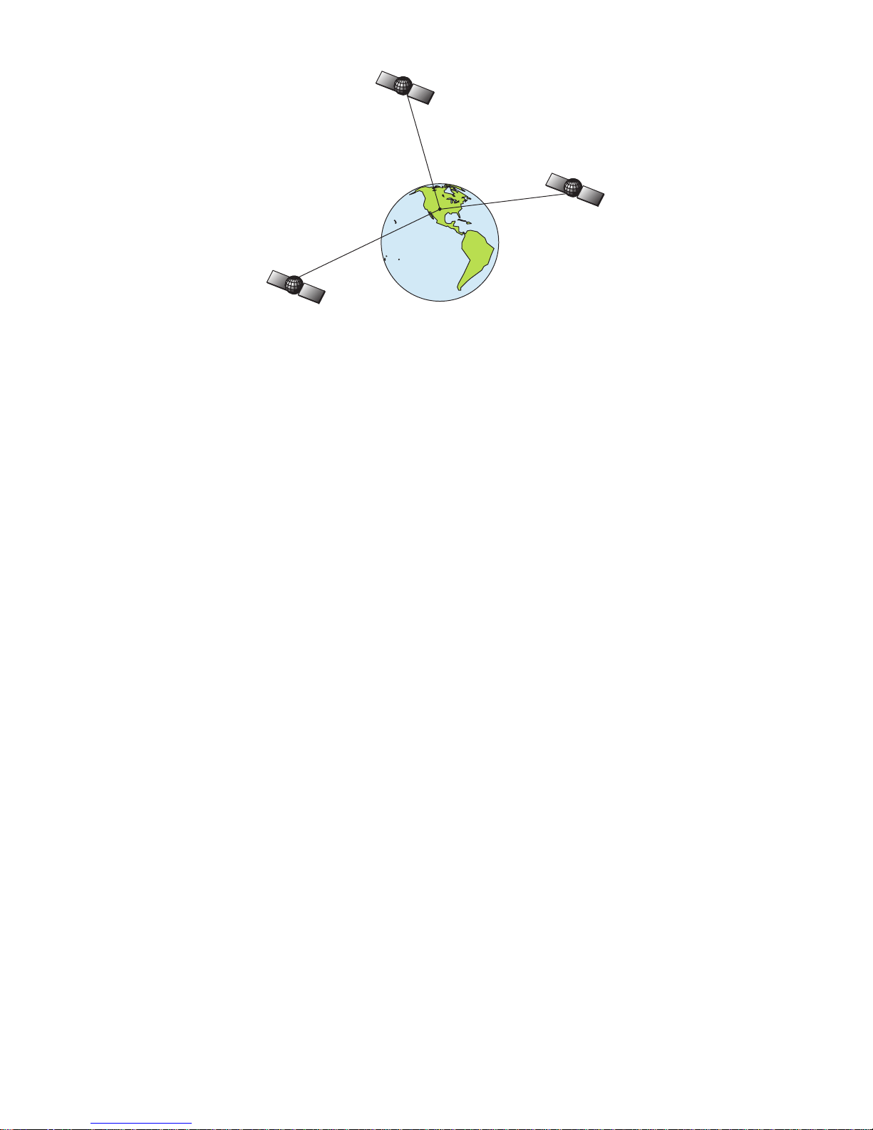
Twenty-four satellites orbit 10,900 nautical miles above the Earth,
passing overhead twice daily. A series of ground stations (with precisely
surveyed locations) controls the satellites and monitors their exact locations in the sky. Each satellite broadcasts a low-power signal that identifies the satellite and its position above the earth. Three of these satellites
are spares, unused until needed. The rest virtually guarantee that at
least four satellites are in view nearly anywhere on Earth at all times.
7
A minimum of three satellites are required to determine a 2D fix.
The system requires signal reception from three satellites in order to
determine a position. This is called a 2D fix. It takes four satellites to
determine both position and elevation (your height above sea level —
also called altitude). This is called a 3D fix.
Remember, the unit must have a clear view of the satellites in order to
receive their signals. Unlike radio or television signals, GPS works at
very high frequencies. These signals can be easily blocked by trees,
buildings, an automobile roof and even your body.
Like most GPS receivers, the iFINDER doesn’t have a compass or any
other navigation aid built inside. It relies solely on the signals from the
satellites to calculate a position. Speed, direction of travel, and distance
all are calculated from position information. Therefore, in order for the
iFINDER to determine direction of travel, you must be moving and the
faster, the better. This is not to say that it won’t work at walking or
trolling speeds — it will. There will be more "wandering" of the data
shown on the display.
GPS alone is plenty accurate for route navigation, but the U.S. Federal
Aviation Administration has special aircraft navigation needs that go
beyond basic GPS. Consequently, the FAA has developed a program to
boost GPS performance with its Wide Area Augmentation System
(WAAS). The FAA commissioned the system on July 11, 2003. EGNOS
(European Geostationary Navigation Overlay Service) is the European
equivalent of WAAS. Like WAAS, it was created to make GPS position
calculation more accurate.
WAAS is designed to increase GPS accuracy to within 7.6 meters vertically
and horizontally, but according to the FAA, it consistently comes within 1-2
meters horizontal and 2-3 meters vertical. It does this by broadcasting correction signals on GPS frequencies. Your unit automatically receives both
GPS and WAAS signals.

8
There, however, are some fringe areas of the U.S., including parts of
Alaska, that do not yet receive robust WAAS coverage. Continued WAAS
development is planned to extend WAAS coverage in the years to come.
WAAS boosts the accuracy of land GPS navigation, but the system is
designed for aircraft. The satellites are in a fixed orbit around the
Equator, so they appear very low in the sky to someone on the ground
in North America. Aircraft and vessels on open water can get consistently good WAAS reception, but terrain, foliage or even large man-made
structures can sometimes block the WAAS signal from ground receivers.
You'll find that using your GPS receiver is both easy and amazingly
accurate. It’s easily the most accurate method of electronic navigation
available to the general public today. Remember that this receiver is
only a tool. Always have another method of navigation available, such
as a map or chart and a compass.
Also remember this unit will always show navigation information in
the shortest line from your present position to a waypoint, regardless of
terrain! It only calculates position. It can’t know what’s between you
and your destination. It’s up to you to safely navigate around obstacles,
no matter how you’re using this product.
How to use this manual: typographical conventions
Many instructions are listed as numbered steps. The keypad and arrow
"keystrokes" appear as boldface type. So, if you're in a real hurry (or
just need a reminder), you can skim the instructions and pick out what
menu command to use by finding the boldface command text. The following paragraphs explain how to interpret text formatting for those
commands and other instructions:
Arrow Keys
The arrow keys control the movement of dotted crosshairs lines (the
cursor) on your mapping screen. The arrow keys also help you move
around the iFINDER menus so you can execute different commands.
They are represented by symbols like these, which denote the down ar-
row key, the up arrow, the left arrow and the right arrow: ↓ ↑ ← →.
Keyboard
The other keys perform a variety of functions. When the text refers to a
key to press, the key is shown in bold, sans serif type. For example, the
"Enter/Save" key is shown as
ENT and the "Menu" key is shown as MENU.
Menu Commands
A menu command or a menu option will appear in small capital letters,
in a bold sans serif type like this:
ADVANCED MODE. These indicate that you
are to select this command or option from a menu or take an action of

9
some kind with the menu item. Text that you may need to enter or file
names you need to select are shown in italic type, such as trail name.
Instructions = Menu Sequences
Most functions you perform with the iFINDER are described as a sequence of keystrokes and selecting menu commands. We've written
them in a condensed manner for quick and easy reading.
For example, instructions for backtracking a trail in Easy Mode would
look like this:
1. Press
MENU|↓ to NAVIGATE TRAIL|ENT.
2. Now, let the iFINDER guide you.
Translated into complete English, step 1 means: "Press the Menu key. Use
the down arrow key to scroll down and select (highlight) the Navigate Trail
command. Press the Enter key."
Also note that throughout this text, we will refer to the iFINDER ExpeditionC as the iFINDER or as the unit.

10
Notes

11
Section 2:
Installation & Accessories
Power
The iFINDER operates from AA batteries or on 3 volts DC using an
optional external power cable with a cigarette lighter adapter. When
the power cable is used, the iFINDER automatically switches to external power. If the external power fails, the unit will switch to battery
power.
Flash memory will keep your stored data safe and accessible for the life
of the product. After the unit is turned off, no battery or external power
is needed to store your data.
Batteries
The unit requires two, 1.5-volt AA batteries. We recommend you use
alkaline batteries for the best trade-off between battery life and cost.
We recommend DURACELL
brand, but other brands will work. If
you're looking for an extended-life battery, the Duracell
ULTRA bat-
tery has performed well in our tests.
You can also use rechargeable AA alkaline batteries, such as those
made by RAYOVAC
, or rechargeable AA nickel metal hydride (NiMH)
batteries. We do not recommend nickel cadmium (NiCd) rechargeable
batteries because we tend to get poor battery life from them.
Rechargeable alkaline batteries will not last as long as standard alkaline batteries. Rechargeable NiMH batteries, however, should give you
suitable battery life.
Lithium batteries are lighter than alkaline, and with some brands of
lithium batteries, the iFINDER ExpeditionC will float. We've tested it
using Energizer
e
2
lithium batteries and it remained afloat.
NOTE:
The battery gauge on the Satellite Status Page may not read accurately with some battery brands because discharge rates can vary
significantly. This is especially true for rechargeables. This battery
gauge was calibrated for alkaline batteries.
Do not mix different battery types. Mixing battery types may cause leakage. (For example, don’t use both alkaline and NiMH batteries at the
same time, and don't use standard alkalines with rechargeable alkalines.)
12
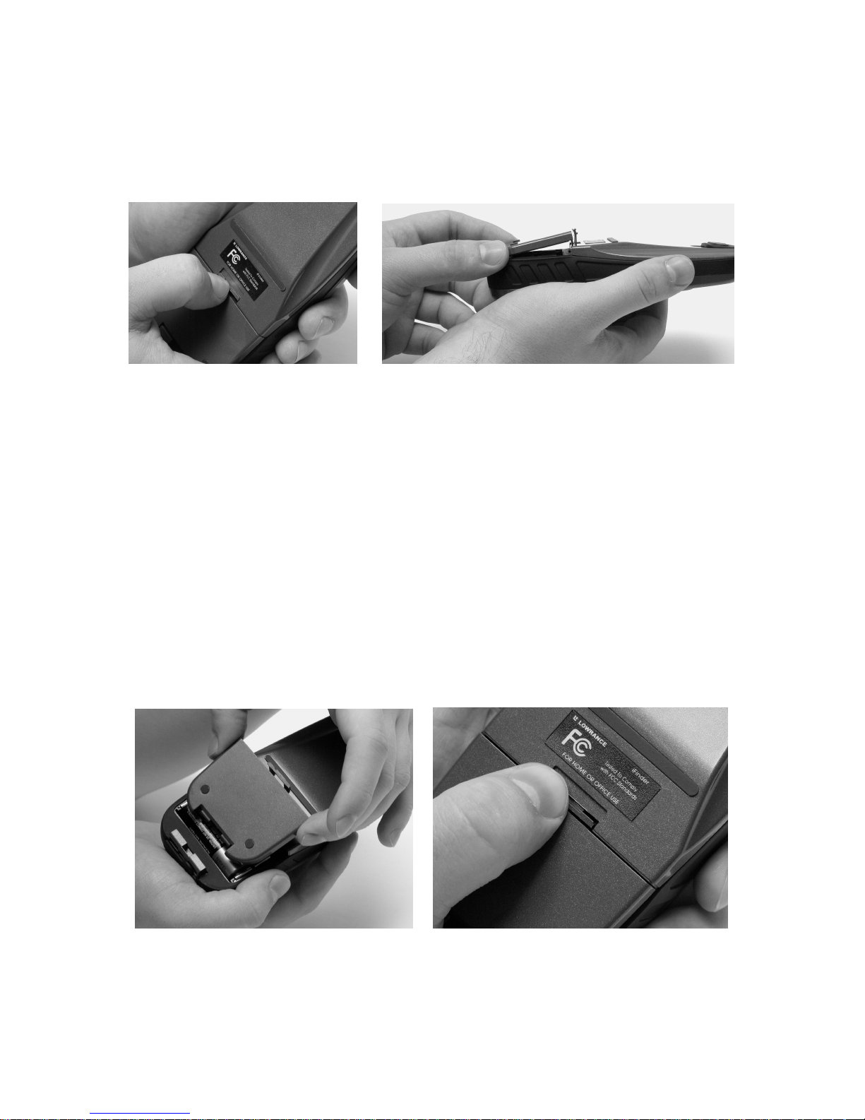
Battery Installation
Turn the unit over so that the back is facing you. With your thumb or
nail, pull back on the small clip to release the battery cover latch as
shown in the following images. Once the latch is released, pull the battery cover out of the grooves in the bottom of the case.
Remove the iFINDER battery cover.
Install the batteries according to the embossed signs in the battery compartment. They show the correct polarity. Point the positive pole of the
upper battery to the left; point the positive pole of the bottom battery to
the right.
NOTE:
Inside the battery compartment is a rotating MMC card lock. The
grip on this lock must be turned parallel with the direction of the
batteries for them to fit properly.
Replace the battery compartment cover. First, align the latch tabs at the
bottom of the cover with the slots at the case's base. Press the cover into
place, then firmly push up on the clip at the top of the cover until it
latches in place. There is usually an audible click when the latch engages.
Replace battery compartment cover. Align tabs with slots
in the base (left). Press latch firmly until it clicks (right).
13
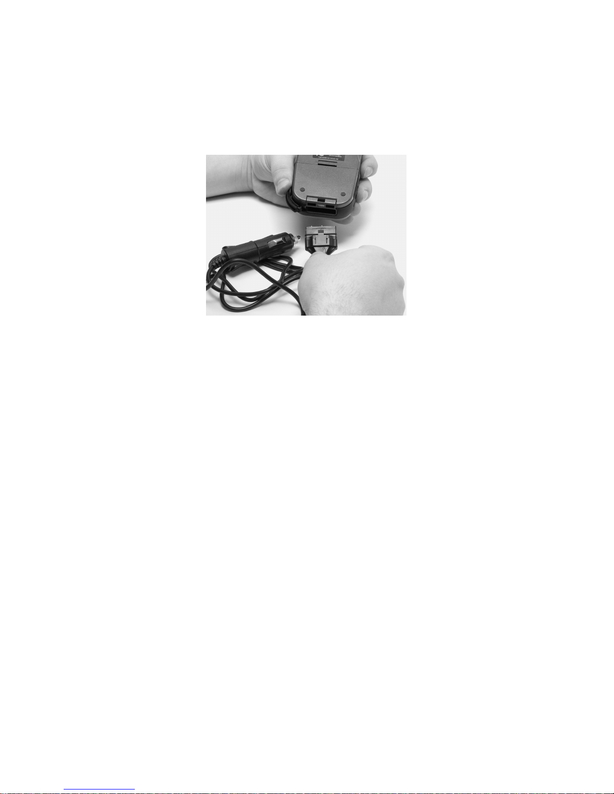
Cigarette Lighter Power Adapter
To use external DC power, plug the power cable's cigarette lighter
adapter into a cigarette lighter receptacle. Next, pull aside the rubber
cover on the bottom of the unit and insert the other connector as shown
in the following image. A small clip on the connector should hold the
connector in place.
Attach external power cable to the iFINDER.
WARNING:
Do not remove the cigarette lighter adapter and splice
the exposed wires directly to a 12-volt power system. The
cigarette lighter adapter contains in the plug a protective fuse and a voltage regulator to convert 12 volts
down to about 3 volts. Without this regulator, connecting
your unit to a 12-volt power source will destroy the unit.
This damage will not be covered by your warranty.
The iFINDER can use two other optional external cables to supply a
NMEA/serial data connection or a combination of power and data. These
cables are discussed in the following segment on NMEA connections.
NMEA Cable Connections
NMEA is a standard communications format for marine electronic
equipment. For example, an autopilot can connect to the NMEA interface
on this unit and receive positioning information. The unit can exchange
information with any device that transmits or receives NMEA 0183 data.
To exchange NMEA data, Lowrance offers an optional data only cable
and a power/data combo cable:
The PC-DI7 is a NMEA/serial communications cable. It has a standard
female DB-9 connector on one end to attach your unit to a computer's
serial communications port.
The PC-DI8 combines a cigarette lighter power adapter with a DB-9
plug for a NMEA/serial com port connection to a laptop computer or

14
other device. This is our favorite cable for connecting the iFINDER ExpeditionC to a laptop computer in a RV or other vehicle. By transmitting NMEA data to the computer, you can get live position data for
GPS-compatible mapping software.
You can also run one of our free Lowrance GPS emulators on your laptop and operate it with real-time position information.
To use it, plug the power adapter into a cigarette lighter socket, plug
the DB-9 connector into a serial port on the computer and attach the
cable to the iFINDER. Then see "Com Port Configuration" in Sec. 5.
MMC or SD Memory Card Installation
Your iFINDER uses a MultiMedia Card to store information, such as
custom maps, waypoints and other GPS data. The unit can also use Secure Digital Cards (SD cards) to store information.
NOTE:
Throughout this manual, we will use the term MMC, but just remember your unit can use an MMC or SD card to store data.
Both of these solid-state flash memory devices are about the size of a
postage stamp. A SD card is slightly thicker than an MMC. As this
manual went to press, MMC and SD cards were available in storage
capacities of up to 1 GB.
Additional MMC cards are available from LEI Extras. See ordering information inside the back cover of this manual. MMCs and SD cards
are also available at many consumer electronics stores.
The MMC slot is located in the battery compartment, beneath the batteries on the right side of the unit. The contact pins are springy, to
make it easier to insert and remove a MMC card.
To remove an MMC
1. Remove battery compartment cover.
2. Remove batteries, if present.
3. Hold unit facedown in right hand. Use your thumb or index finger
and press down on the center of the MMC label.
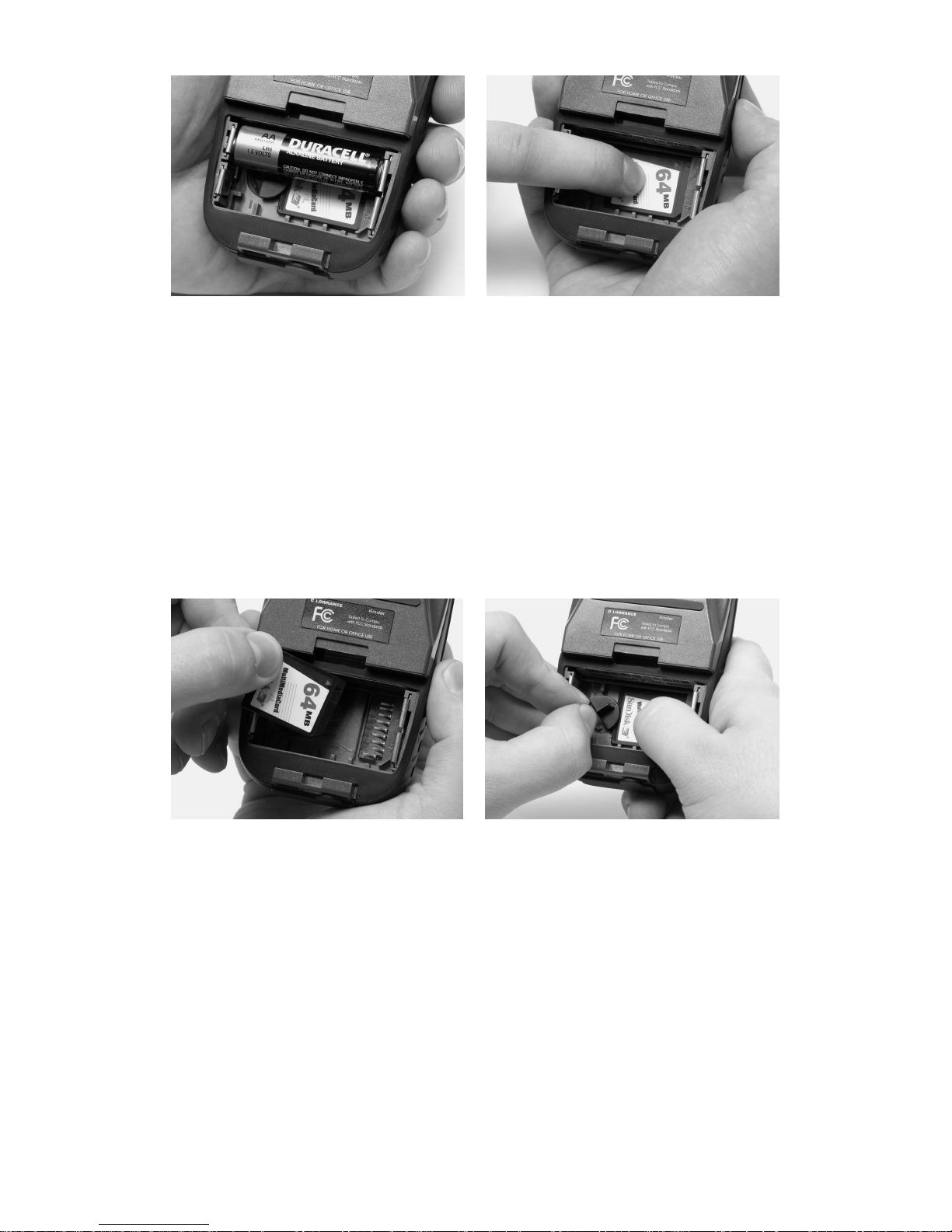
15
Remove an MMC Card.
4. Drag the MMC from the slot into the battery compartment.
5. Turn the iFINDER face up and give it a shake to dump the MMC
into your hand or onto a work surface.
To add an MMC or SDC
1. Remove battery compartment cover.
2. Remove batteries, if present.
3. Hold unit facedown in right hand. Drop the MMC card into the slot,
label-up, with the notched edge toward the right.
4. Press down on the center of the label and slide the card to the right.
Add an MMC Card.
5. Turn the plastic rotating card lock until it holds the card firmly in
place with the grip parallel to the direction of the batteries.
6. Replace the batteries and battery cover.
Mapping Resources
The iFINDER Expeditionc works with FreedomMaps, NauticPath
USA, Fishing Hot Spots
Elite, LakeMaster ProMaps and Navionics
charts.
FreedomMaps are pre-made custom maps that cover multiple states,
provinces, countries or other geographic regions on a single memory

16
card. They give you all the features found in our MapCreate™ mapping
software, but without the necessity of using a computer. FreedomMaps
are available for the United States, Canada and Europe.
Like custom maps built in MapCreate, the custom map on a FreedomMap
card contains all of these features: rivers/lakes/tributaries; more than
60,000 critical navigation aids; more than 10,000 wrecks/obstructions in
coastal and Great Lakes waters; interstate/federal/state highways; interstate exit services; searchable Points-of-Interest (POI) database including:
airports, hotels, restaurants, entertainment, emergency services; rural
roads and city streets; cities and towns; railways; key landmarks; searchable street intersections and street addresses; national parks and forests
with boundaries; wildlife preserves; and more!
NauticPath charts offer the highest level of offshore/coastal navigation
detail and information pre-loaded on a digital mapping card. NauticPath has electronic charts covering the East and West coasts, Hawaii, the Gulf Coast, Alaska, the Bahamas, Puerto Rico and US Virgin
Islands — all on one memory card!
Fishing Hot Spots Elite provides superb coverage of more than 2,000 of
America's premier inland fishing lakes. The mapping detail, which includes depth contour lines and excellent shoreline detail, is preloaded
onto one of four digital mapping cards.
LakeMaster ProMaps are high definition maps loaded on plug-and-play
digital media cards. The cards cover Minnesota and Wisconsin.
FreedomMaps, NauticPath charts, Fishing Hot Spots Elite and
LakeMaster ProMaps are available through LEI-Extras. To order a
card (or for list of areas available) see ordering information in the back
of this manual or visit the LEI web site at www.lei-extras.com. The
iFINDER also supports Navionics charts, which may be ordered at the
Navionics web site.
External Antenna
A GPS antenna requires a clear view of the sky for optimum operation.
Inside a vehicle, your iFINDER can sometimes maintain satellite lock
while sitting on the seat beside you, but we don't recommend this for
optimum performance.
Since the view is restricted to what can be seen through the windows,
this operating mode will reduce position accuracy and will increase the
chance of losing satellite lock. Inside a vehicle, the unit operates best
with an optional external antenna mounted on the windshield, on the
dash or on top of the vehicle.

17
The optional external antenna can use a magnetic base that allows
temporary mounting on any flat ferrous metal surface. A suction-cup
mount allows you to attach the antenna to a windshield.
The iFINDER ExpeditionC can use the passive FA-8 antenna or the
active RAA-3 antenna. The active antenna offers a further performance
boost by amplifying the satellite signals it receives. This is especially
helpful when operating in areas like dense forests, which can obstruct
GPS signals. Your unit will automatically switch between the active
RAA-3 and its internal antenna (located in the top of the case). If you
purchase the passive FA-8, you must use a menu check box to manually
switch between it and the internal antenna. See the topic "External
Passive Antenna" in Sec. 5.
Attach the iFINDER antenna to windshield bracket with two screws.
You may achieve good results by placing the external antenna on the
top of the dash, at the base of the windshield. A piece of the rubber nonskid shelf liner material available in recreational vehicle supply stores
will also help hold the antenna in place.
To use the antenna: Mount it in a location with an unobstructed view of
the sky. Plug the connector into the unit's antenna socket, located on
the back, in the upper left corner of the case.
R-A-M Bracket Mounting Systems
Several R-A-M mounting brackets are available for your iFINDER.
There are permanent mounts and temporary mounts suitable for virtually any boat, aircraft, vehicle, even motorcycle handlebars.

18
Two R-A-M mounting systems for your unit.
One model has a mounting arm and cradle attached to a swivel ball
plate that can be screwed or bolted to a supporting surface. Another has
a moldable, weighted, rubber foot and gooseneck for support virtually
anywhere without screws or adhesives. R-A-M even has suction cup
bases for attachment to windscreens or fiberglass surfaces. See your
Lowrance dealer or visit the LEI web site for the latest options. Accessory ordering information is on the inside back cover of this manual.
For a complete look at the many mounting options, visit the R-A-M web
site at www.ram-mount.com.
Other Accessories
Other iFINDER accessories include MMC cards, MMC card readers and
MapCreate™ 6 custom mapping software for your computer. (The
iFINDER ExpeditionC Plus model ships with the GPS Accessory Pack,
which is composed of the MapCreate CDs, the card reader and one memory card.)
If these accessories are not available from your dealer, see the accessory ordering information on the inside back cover of this manual.
MapCreate™ 6 CD-ROM and MMC card reader for USB ports.
19
Section 3:
Easy Mode Operation
This section addresses Easy Mode operation for the iFINDER's main
GPS functions. The principles are the same in both operating modes, so
this discussion also serves as a good introduction to Advanced Mode
work.
Before you turn on the iFINDER, it's a good idea to learn about the different keys, the three Page screens and how they all work together.
BUT, if you just can't wait to get outside, grab the batteries and turn to
the one-page Quick Reference on page 28.
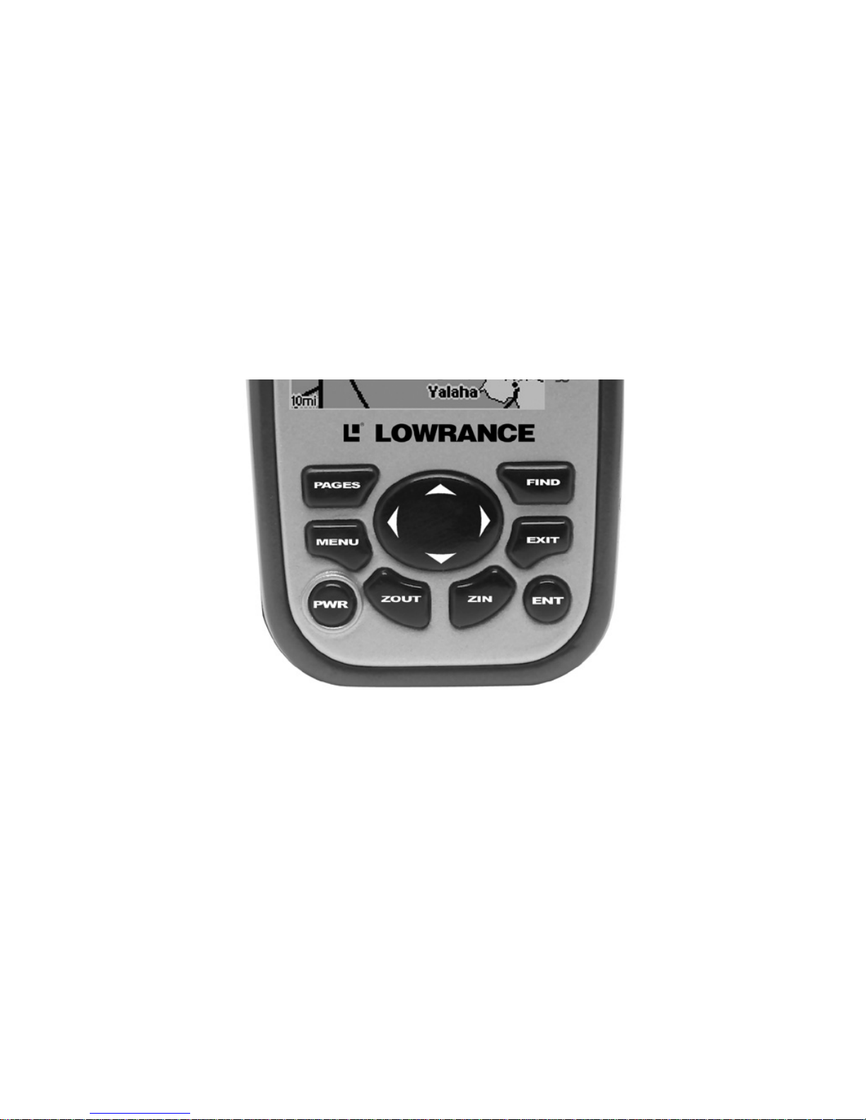
Keypad
iFINDER ExpeditionC keypad.
1. PWR/LIGHT – The PWR key turns the unit on and off and activates
the backlight.
2. PAGES – Pressing this key switches the unit between four page
screens in Easy Mode. (Satellite, Navigation, Compass and Map.) Each
page represents one of the unit's major operation modes.
3. MENU – Press this key to show the menus, which allow you to select
or adjust a feature from a list.
4. ARROW KEYS – These keys are used to navigate through the
menus, make menu selections, move the map cursor and enter data.
5. ENT – The enter key allows you to save data, accept values or execute menu commands.
1
4
2
8
7
9
6
3
5
20
6. EXIT – The Exit key lets you return to the previous screen, clear
data or close a menu.
7. FIND – The Find key launches the iFINDER search menus and
some navigation functions.
8. ZOUT – (Zoom Out) – This key lets you zoom out the screen to see a
larger geographic are on the map. Less detail is seen as you zoom out.
9. ZIN – (Zoom In) – This key lets you zoom in the screen to see greater
detail in a smaller geographic area on the map.
Power/lights on and off
To turn on the unit, press PWR. To turn on the backlight, press PWR
again. Pressing PWR again will turn off the backlight. Press EXIT to
message or alarm displays.
Turn off the unit by pressing and holding the
PWR key for 3 seconds.
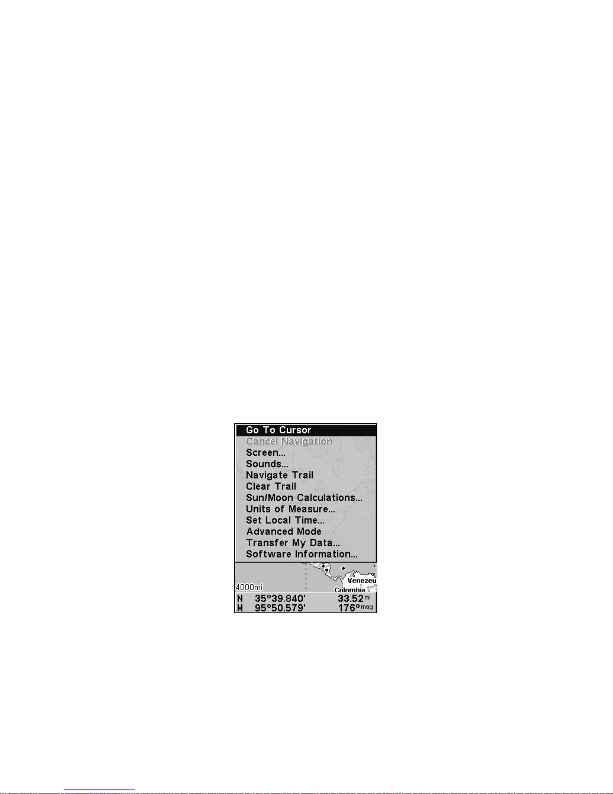
Main Menu
Easy Mode has a single Main Menu, which contains function and setup
option commands. The lessons in this section will deal only with functions
— the basic commands that make the iFINDER do something. The
iFINDER will work fine for these lessons with the factory default settings.
But, if you want to learn about the various options, see Sec. 5, System
Setup and GPS Setup Options.
Main Menu, Easy Mode.
The Main Menu commands and their functions are:
Go To Cursor: navigates to the current cursor position on the map
Cancel Navigation: turns off the navigation command after you have
reached your destination.

21
Screen: changes the contrast or brightness of the display screen and
backlight delay.
Sounds: enables or disables the sounds for key strokes and alarms and
sets the alarm style.
Navigate Trail: sets up navigation back to the start of the current
trail.
Clear Trail: clears all the points stored in the plot trail.
Sun/Moon: finds the rising and setting time of the sun and the moon.
Units of Measure: allows users to change units for Speed/Distance,
Time, Date, Heading, Altitude, Depth and Pressure.
Set Local Time: sets the time for your local time zone.
Advanced Mode: used to switch from Easy Mode to Advanced Mode.
Easy Mode shows only the most commonly used features to simplify the
interface and simplify operation.
Transfer My Data: load or save GPS Data Files containing waypoints,
routes, trails and event marker icons.
Software Information: shows the product name and software version
of the unit's operating system software, as well as copyright notices.
Pages
Easy Mode has a three page display. They are Satellite Status Page,
Navigation Page and Map Page. The pages are accessed by pressing the
PAGES key. Pressing PAGES repeatedly scrolls through the three
screens in an endless loop.
Satellite Status Page
The Satellite Status page, shown in the following images, provides detailed information on the status of the iFINDER's satellite lock-on and
position acquisition. To get to the Satellite Status Page, press
PAGES
repeatedly until it appears on the screen.
No matter what page you are on, a flashing current position indicator/question mark symbol and flashing GPS data displays indicate satellite lock has been lost and there is no position confirmed. This page
shows you the quality and accuracy of the current satellite lock-on and
position calculation.
WARNING:
Do not begin navigating with this unit until the numbers
have stopped flashing!
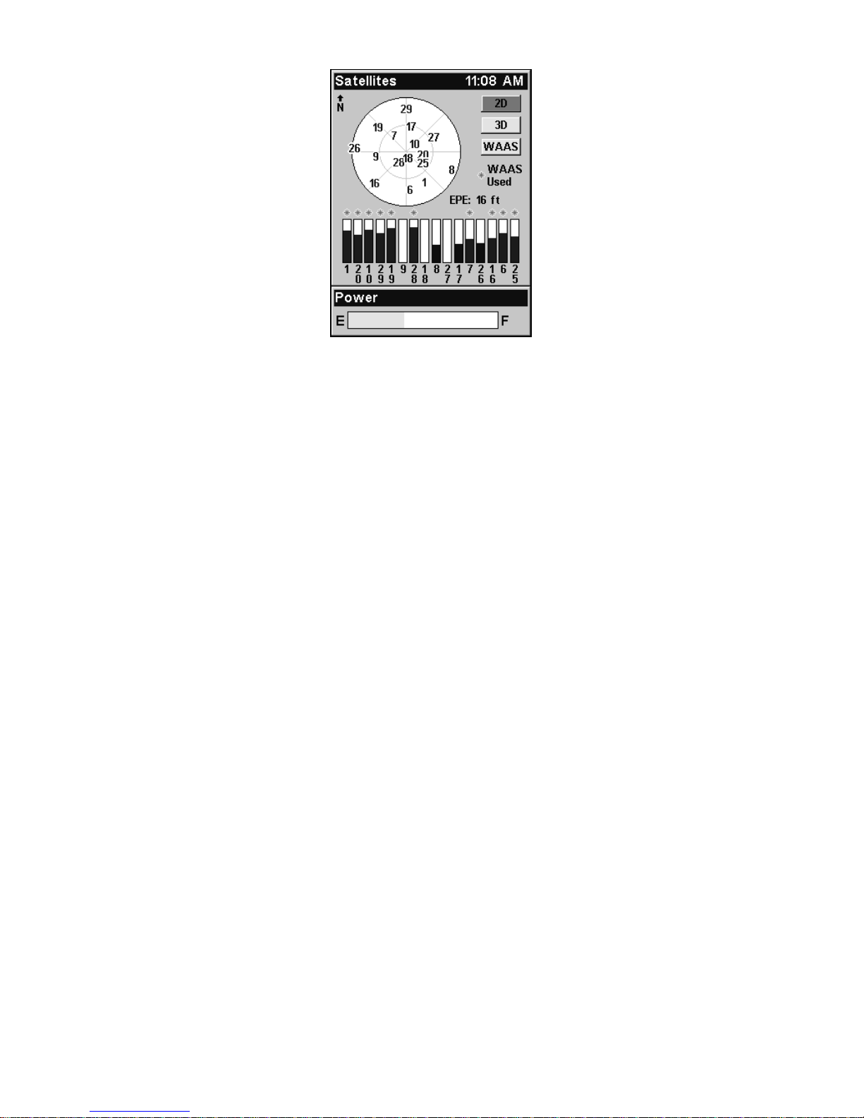
22
Satellite Status Page.
This screen shows a graphical view of the satellites that are in view.
Each satellite is shown on the circular chart relative to your position.
The point in the center of the chart is directly overhead. The small inner ring represents 45° above the horizon and the large ring represents
the horizon. North is at the top of the screen. If you hold the unit facing
north, you can use it to see which satellites are obstructed by obstacles
in your immediate area. The GPS receiver is tracking satellites that are
in bold type. The receiver hasn't locked onto a satellite if the number is
grayed out, which means it isn't being used to resolve the position.
Beneath the circular graph are the bar graphs, one for each satellite in
view. Since the unit has 16 channels, it can dedicate one channel per
visible satellite. The taller the bar on the graph, the better the unit is
receiving signals from the satellite.
The Estimated Position Error (EPE), shown above the bar graphs, is
the expected error from a benchmark location. In other words, if the
EPE shows 50 feet, then the position shown by the unit is estimated to
be within 50 feet of the actual location. This also gives you an indicator
of the fix quality the unit currently has. The smaller the position error
number, the more accurate the fix. If the position error flashes dashes,
then the unit hasn't locked onto the satellites and the number shown
isn't valid.
Navigation Page
At the center of the Navigation Page is a compass rose. It shows direction of travel and the direction to a recalled waypoint. When you're not
navigating to a waypoint or destination, the navigation screen looks
like the one in the following image. No graphic course information is
displayed. Your position is shown by an arrow in the center of the
screen. Your trail history, or path you've taken, is illustrated by a line

23
extending from the arrow. The arrow pointing down at the top of the
compass rose highlights your current track (direction of travel).
Navigation Page, recording a trail, traveling east.
When navigating to a waypoint or following a route, the Navigation
screen looks like the one shown in the next image. Your ground speed,
track, distance, course and bearing to a waypoint, all can be shown
digitally on this screen.
The current cross-track error is shown in the XTK box. This is the distance you are off-course to the side of the desired course line. The
course line is an imaginary line drawn from your position when you
started navigating to the destination waypoint. It's shown on the navigation page as a vertical dotted line.
Lines on either side of the present position show the current cross track
error range. The default for the cross track error range is 0.20 mile. For
example, if the present position symbol touches the right cross-track
error line, then you are 0.20 mile to the right of the desired course. You
need to steer left to return to the desired course. You can use the
ZIN or
ZOUT keys to change the cross track error range. A circular symbol il-
lustrating your destination (waypoint) appears on the screen as you
approach the waypoint.
Travel Time is the time it will take to reach a destination at the present closing speed. Arrival Time is the local time it will be when you arrive at the destination, based upon the present closing speed and track.
Compass
rose
Track or compass heading indicator, showing direction of travel
Navigation
information
data boxes
Present position
arrow
Trail line

24
Navigation Page, going to cursor. Driver is headed east (a 68º track)
toward a cursor location 68º (bearing) away. The cross track error
range (white corridor) is 0.20 miles either side of the course. The
driver is headed toward the cursor location, which is 0.17 miles away.
The vehicle is basically on course (off course only 1 foot). Traveling at
34 mph. The driver will arrive at the waypoint in 18 seconds.
Map Page
The map screens show your course and track from a bird's-eye view. By
default, this unit shows the map with north always at the top of the screen.
(This can be changed using options in Advanced Mode. See the topic Map
Orientation, in Sec. 5.) If you're navigating to a waypoint, the map also
shows your starting location, present position, course line and destination.
NOTE:
When our text says, navigating to a waypoint, it is synonymous
with navigation to any selected item, whether it is a waypoint you
made, a map feature or an item from the POI database.
Using the map is as simple as pressing the
PAGES key. A screen similar to
those in the following images will appear. The arrow flashing in the center
of the screen is your present position. It points in the direction you're traveling. The solid line extending from the arrow is your plot trail or path
you've taken. Remember, a flashing question mark/arrow symbol or flashing text displays means the iFINDER has not yet calculated a position.
The zoom range is the distance across the map. This number is shown
in the lower left corner of the screen. In the first example below, the
range is 4,000 miles from one side of the map to the other. The Zoom In
and Zoom Out keys zoom the map to enlarge or reduce its coverage
area. There are 40 zoom ranges, from 0.02 miles to 4,000 miles.
Waypoint
symbol
Bearing
arrow
Trail line
Cross track
error range
(off course
indicator)
Navigation
information
data boxes
Destination
name

25
Map Page opening screen (left); Map zoomed to 100 miles (center); Map
zoomed to 6 miles (right). Over Zoomed means you have reached the
detail limits in an area covered only by the basic background map.
Zooming in any closer will reveal no more map details because a high-
detail custom map for this area has not been loaded on the MMC.
If you're using the factory-loaded background map, the maximum zoom
range for showing additional map detail is 8 miles. You can continue to
zoom in closer, but the map will be enlarged without revealing more
map content (except for a few major city streets). Load your own highdetail custom map made with MapCreate and you can zoom in to 0.02
miles with massive amounts of accurate map detail.
Map Pages with high-detail map of an urban area loaded on the MMC.
Arterial streets appear at the 4-mile zoom range (left), with a few Point
icons visible. Numerous dots representing Points of Interest become
visible at the 3-mile range (center). At the 0.4-mile zoom (right), you
can see an interstate highway with an exit, major and minor streets as
well as Point of Interest icons.
Background map vs. MapCreate map content
The background map includes low-detail maps of the whole world containing cities, major lakes, major rivers, political boundaries and medium-detail maps of the United States.
Medium-detail U.S. maps contain all incorporated cities; shaded metropolitan areas; county boundaries; shaded public lands (such as national
forests and parks); some major city streets; Interstate, U.S. and state

26
highways; Interstate highway exits and exit services information;
large- and medium-sized lakes and streams and more than 60,000
navigation aids and 10,000 wrecks and obstructions in U.S. coastal and
Great Lakes waters.
MapCreate custom maps include massive amounts of information not
found in the background map. MapCreate contains the searchable
Points of Interest database, all the minor roads and streets, all the
landmark features (such as summits, schools, radio towers, etc.); more
rivers, streams, smaller lakes and ponds and their names.
What's more important is the large-scale map detail that allows your
GPS unit to show a higher level of position accuracy. For example, the
background map would show you the general outline and approximate
shape of a coastline or water body, but the higher detail in MapCreate
shows the shoreline completely and accurately (finer detail). Many
smaller islands would not be included in the background map, but are
in MapCreate.
When the map is zoomed out far enough, most POIs appear as square
dots (left). As you zoom in closer, the symbols become readable icons.
In the 0.3-mile zoom example (right), the cursor has selected Cholita's
Mexican Restaurant POI, which triggers a pop-up box with the POI
name. This pop-up box works on POIs at any zoom range.
Tip:
In some urban areas, businesses are so close to one another their
POI icons crowd each other on the screen. In the preceding figure,
you can see a packed string of POIs all along the west half of 11th
Street. You can reduce screen clutter and make streets and other
map features easier to see by turning off some POIs categories. To
see how, check the text on Map Detail Category Selection, in Sec. 5.
School POI
POI
Pop-up
Restaurant
POI
POI
Markers
Position,
distance and
bearing data
Zoom
Range
Cursor line
Interstate
Major Street

27
It shows how to use the Map Categories Drawn menu to turn individual POI displays off and on. Even though their display is turned
off, you can still search for POIs and their icons will pop-up when
the unit finds them.
The following page contains a 12-step quick reference for Easy Mode
operation. If you don't want to carry the manual with you as you practice with the iFINDER, you might consider photocopying this quick reference page and tucking it into your pocket.

28
IFINDER Expeditionc Easy Mode Quick Reference
Start outdoors, with a clear view of the open sky. As you practice, try
navigating to a location a few blocks away. Navigation in too small a
space, like a backyard, will constantly trigger arrival alarms.
1. Install two AA batteries and an MMC card in the battery compartment on back of case. (See installation details beginning on page 11.)
2. To turn on the iFINDER, press
PWR key.
3. Opening screen displays map of North America at the 4,000-mile
zoom range. Rotate through the three main Page screens (Map Page,
Satellite Status Page and Navigation Page) by repeatedly pressing
PAGES key. Switch Pages to display Satellite Status Page.
4. Wait while unit locates satellites and calculates current position. Process
is visible on Satellite page. This takes an average of 1 minute or less under
clear sky conditions (unobstructed by terrain or structures.) When the unit
acquires position, a tone sounds and a position acquired message appears.
5. With position acquired, press
PAGES key to display Map Page, which
shows a bird's eye view of the earth. You can move around the map by
zooming out, zooming in or scrolling.
Zoom in closer to see greater detail: press
ZIN (zoom in key.)
Zoom out to see more area, less detail: press
ZOUT (zoom out key.)
Scroll map north, south, east or west using arrow keys ↑ ↓ → ←.
To stop scrolling and return to current position on map, press
EXIT key.
6. Set Home waypoint at your current position so you can navigate back
here: press
ENT|ENT.
7. Zoom/scroll map to find a nearby object or location. Use arrow keys to
center cursor crosshairs over the map object or location.
8. To navigate to the selected location, press
MENU|ENT|EXIT. Follow
steering arrow on Map Page or compass bearing arrow on Navigation Page.
9. At destination, Arrival Alarm goes off. To clear it, press
EXIT. Cancel
navigation: press
MENU|↓ to CANCEL NAVIGATION|ENT|← to YES|ENT.
10. Navigate back home by
GO HOME or NAVIGATE TRAIL. To Go Home:
press
FIND|↓ to GO HOME|ENT and follow navigation arrows. To Navi-
gate Trail: press
MENU|↓ to NAVIGATE TRAIL|ENT. Wait while route is
calculated, then follow arrows.
11. Back home, Arrival Alarm goes off; press
EXIT. Cancel navigation:
press
MENU|↓ to CANCEL NAVIGATION|ENT|← to YES|ENT.
12. To turn off the iFINDER, press and hold
PWR key for three seconds.

29
Find Your Current Position
When you turn on the iFINDER, it automatically searches for satellites
and under clear sky conditions, calculates its position in approximately
one minute or less.
NOTE:
Clear sky means open sky, unobstructed by terrain, dense foliage or
structures. Clouds do not restrict GPS signal reception.
If satellite acquisition takes longer than usual, you may be inside a
structure, a vehicle or in terrain that is blocking signal reception. To
correct this, be sure you are positioned so the unit has as clear a view of
the sky as possible, then turn the unit off and back on again.
Moving Around the Map: Zoom & Cursor Arrow Keys
The map is presented from a bird's eye view. The current zoom range
shows in the lower left corner of the screen.
1. Press the
ZIN key (zoom in) to move in closer and see greater detail in
a smaller geographic area.
2. Press the
ZOUT key (zoom out) to move farther away and see less map
detail in a larger geographic area.
When you are walking or riding in a vehicle, the map will automatically
move as you move. This keeps your current location roughly centered
on the screen.
You can scroll the map northward, southward, eastward or westward
by using the arrow keys, which will launch the cursor crosshairs. This
allows you to look anywhere on the map. To clear the cursor, press
EXIT
and the map will revert to the current or last known position.
The selected airport to the northwest is 4.2 miles away.
Distance
measured
by cursor
Cursor line
Selected airport
Cursor line

30
Tip:
Use the cursor to determine the distance from your current position
(or last known position, when working indoors) to any map object or
location. Use the arrow keys to position the cursor over the object or
place. The distance, measured in a straight line, appears in the data
box at the bottom of the map. Press
EXIT to clear the cursor.
Selecting Any Map Item with the Cursor
1. Use the zoom keys and the arrow keys to move around the map and
find any item you wish to select.
2. Center the cursor crosshairs on the desired object. On most items, a
pop-up box will give the name of the selected item.
You will also notice a red border surrounds the item when it is selected.
Once that happens and you press
FIND, the Find Menu will pop up with
SELECTED ITEM listed at the top of the menu. Press ENT to see the Way-
point Information screen for the selected item.
Searching
Now that you have seen how the iFINDER can find where you are, let's
search for something else. Searching is one of the most powerful features in the Lowrance GPS product line.
In this example, we'll look for the nearest fast-food restaurant. For more
information on different types of searches, refer to Sec. 6, Searching.
NOTE:
This example requires the Point of Interest (POI) database included
with a high-detail MapCreate 6 custom map.
After the iFINDER has acquired a position:
1. Press
FIND|↓ to MAP PLACES|ENT|↓ to POI-RESTAURANTS.
2. You could search the entire restaurant category, but in this example
we will narrow our search. Sub Category will already be highlighted, so
press → to
FAST FOOD CHAINS|ENT|ENT.

31
Find Map Places Menu (left); Category Selection menu (center) with
list of the nearest restaurants (right).
3. A list of restaurants will appear with the closest at the top of the list
and the one furthest from you at the bottom of the list. The location
nearest you will be highlighted.
4. If you wanted, you could select a different restaurant, but for
now,
we will accept the nearest one
. Press ENT.
5. The POI's Waypoint Information screen appears. (This is how you
can use the iFINDER as a business phone directory!) If you wanted to
navigate there, you could press Enter, since the
GO TO command is
highlighted. But we just want to see it on the map, so press → to
FIND ON
MAP|ENT.
Subcategory highlighted in the Find By Nearest menu (left). POI in-
formation screen showing Go To command (left). The Find On Map
command is selected (right).
6. The iFINDER's map appears, with the cursor crosshairs highlighting
the restaurant's POI symbol. A pop-up name box identifies the POI. A
data box at the bottom of the screen displays the location's latitude,
longitude, distance and bearing.

32
Map screen showing found Waypoint.
7. To clear the search and return to the main page display, press EXIT
repeatedly. Before you exited out of the Search menus, you could have
gone looking for another place.
NOTE:
Search works from mapping and POI data loaded in the unit. If you
have not loaded a high-detailed custom map covering the desired
search area, you may not find much.
Set Home Waypoint
A waypoint is an electronic address, based on the latitude and longitude of a position on the earth. Easy Mode allows you to save two waypoints (Home and Man Overboard).
To save a Home Waypoint:
1. Press and release
ENT.
2. A message appears asking if you want to save your location as the
home waypoint. Select
YES and press ENT. The waypoint is marked by
an X, labeled Home.
Save Home Waypoint menu (left). Home waypoint with X symbol and
name (right). When selected by the cursor, the pop-up box appears.
Pop-up box

33
The example shows the home waypoint set at the cursor location. If the
cursor was not active, the point would be placed at the current position.
Caution:
Saving a new Home waypoint will overwrite and erase the previous Home waypoint.
Go Home
This command will automatically take you back to the Home waypoint
you created.
1. Press
FIND|↓ to GO HOME |ENT and follow navigation arrows on the
Map Page or the compass rose on the Navigation and Compass Pages.
To cancel navigation, press
MENU|↓ to CANCEL NAVIGATION|ENT|← to
YES|ENT. The iFINDER stops showing navigation information.
Set Man Overboard (MOB) Waypoint
One of boating's most terrifying events is having a friend or family
member fall overboard. This unit has a man overboard feature that
shows navigation data to the location where the feature was activated.
To activate it, press the
ZOUT and ZIN keys at the same time. Your posi-
tion at the time these keys are pressed is used as the man overboard
position.
Caution:
Saving a new Man Overboard waypoint will overwrite and erase
the previous Man Overboard waypoint.
Navigate Back to MOB Waypoint
Find your way back to the position with the Navigation Page or Map
Page. When MOB is activated, the Navigation Page automatically
shows the compass rose with its bearing arrow pointing toward the
man overboard position. The destination name says Going To Man
Overboard and the Map Page displays a Man Overboard waypoint, represented by a human figure. The steering arrow will guide you to that
position. The man overboard position is stored in the waypoint table for
future reference. It can be edited the same as any other waypoint in
Advanced Mode. This prevents the inadvertent loss of the current Man
Overboard position.
Tip:
You don't need to have an emergency to use the MOB waypoint. In
Easy Mode, it is the only way you can set a waypoint other than the
Home waypoint. When you set the MOB point, cancel navigation
and use it like a regular waypoint. (Remember, you can set 1,000
waypoints in Advanced Mode.)

34
To cancel navigation to MOB, press
MENU|↓ to CANCEL NAVIGA-
TION
|ENT|← to YES|ENT. The iFINDER stops showing navigation in-
formation.
Navigate to Cursor Position on Map
The GO TO CURSOR command navigates to the current cursor position on
the map. It is a quick and handy way to navigate to anything you can
see on the map display.
1. Use the cursor with the zoom in and zoom out keys to maneuver
around the map until you find a location you would like to visit.
2. Center the cursor over the location to select it. See the example below. Many map items such as waypoints, Points of Interest, towns, etc.,
can be selected and appear highlighted with a pop-up box. Other items,
like a river or a street intersection, will not appear highlighted, but the
cursor will take you to those locations just the same.
Navigate to cursor. In this example, the cursor
crosshairs are centered on Oologah, Oklahoma.
3. Press MENU|ENT and the iFINDER will begin navigating to the cur-
sor location.
The Map Page will display a course line from your current position to
the cursor position. The Navigation Page displays a compass rose
showing navigation information to your destination. See the following
examples.

35
The 15-mile zoom figure (left) shows the course line connecting your
current position to your destination. The 60-mile zoom (center) shows
both current position and destination on screen. The Navigation Page
(right) will also show navigation information.
To stop navigating to the cursor, use the Cancel Navigation command:
press
MENU|↓ to CANCEL NAVIGATION|ENT|← to YES|ENT. The iFINDER
stops showing navigation information.
Navigate to a Point of Interest
For POIs in view on the map, you can use the Navigate to Cursor command above. Use the cursor to select the POI.
Another method involves searching for POIs by pressing the
FIND key
and selecting
MAP PLACES. (For instructions on POI searches, see the
searching example earlier in this section or turn to Sec. 6, Searching.)
After you have selected
MAP PLACES and pressed ENT, a list of map cate-
gories will appear. Use ↓ ↑ to highlight a category and press
ENTER.
The
FIND BY MENU will appear with two options: NAME and NEAREST. Select
NEAREST and press ENT. A list of locations will appear with the one near-
est you highlighted at the top. Press
ENT, which will launch the way-
point information screen. The
GO TO command will be highlighted at the
bottom of the screen, so press
ENT. The iFINDER begins showing navi-
gation information to the item.
To cancel navigation, press
MENU|↓ to CANCEL NAVIGATION|ENT|← to
YES|ENT. The iFINDER stops showing navigation information.
Creating and Saving a Trail
A trail or plot trail, is a history of the path you have taken. On the
screen, trails are represented by a solid line extending from the back of
the current position arrow.
With the default auto setting, the iFINDER creates a trail by placing a
dot (trail point) on the screen every time you change directions. (The
method used for creating a trail and the trail update rate can be adjusted in Advanced Mode. See Sec. 5 for Trail Options.)

36
Navigate Trail
In Easy Mode, this unit automatically creates a plot trail when turned
on. The trail is saved in memory when the unit is turned off. The
iFINDER continues recording the same trail until you clear the trail,
which erases the old trail and begins recording a new trail.
NOTE:
The iFINDER can record up to 9,999 points per trail, which can be
adjusted in Advanced Mode. The default setting is a maximum of
2,000 points. When trail length exceeds the maximum setting, the
unit begins recording the trail over itself.
In Advanced Mode, you can save and recall up to 10 different plot
trails, which may be copied to your MMC card.
Caution:
You also have the option of turning off trail recording in Advance Mode. If the option is left off when you switch modes, you
will not be able to take advantage of the automatic trail creation
feature in Easy Mode.
Displaying a Saved Trail
The trail is automatically displayed in Easy Mode by default. Trail display can be turned off and on only in Advanced Mode.
Navigating or Backtracking a Trail
There are two methods for following your back trail.
The simplest requires no menu commands, but provides no navigation information during the trip. The
other requires only three keystrokes and provides a
full range of navigation data. Try both methods and
see which you prefer. When walking, visual back
trailingis better at following each turn on a footpath. At faster speeds, like on a highway or water,
the Navigate Trail command is handy.
Visual Back Trailing
1. On the Map Page, zoom (
ZIN or ZOUT) so your trail
is visible.
2. Begin moving and watch the Map. Walk so your current position arrow follows the trail.
Navigate a Back Trail
1. Press
MENU|↓ to NAVIGATE TRAIL|ENT.
2. Begin moving and let your iFINDER guide you.

37
NOTE:
If you are already located at or near the beginning of your back
trail, the arrival alarm will go off as soon as you hit Enter. Just
press
EXIT to clear the alarm and proceed.
On the map, your original trail is visible as a solid line, along with a
roughly parallel dotted line indicating the back trail to follow. The map
contains a steer arrow in the lower right corner. This arrow shows you
where to steer to reach the next waypoint on the trail.
The Navigation Page will also show the trail line and a bearing arrow,
which points to the next waypoint on the trail.
As you travel, the arrival alarm will go off when you get close to a waypoint, and the steer arrow (on the map) and bearing arrow (on the compass rose) will swing around and point to the next waypoint on the
trail. Press
EXIT to clear the alarm.
Navigate trail, map views: Driver is southbound heading straight to-
ward trail point 6 (left). The steer arrow tells the driver to go straight.
Southbound driver (right) has reached point 6 and must turn east to
follow trail. The steer arrow swings around to the left (east), toward
the next trail waypoint (arrival alarm message turned off for clarity.)
Back trail
dotted line
Trail point
Steer arrow
Present
position
arrow
North

38
Navigate trail, navigation page (compass rose) views: Driver is east-
bound heading straight toward trail point 5 (left). The bearing arrow
shows the trail point is due east (straight ahead.) Driver (right) has
reached trail point 5 and must turn south to follow the trail. Arrival
alarm goes off and bearing arrow swings around to right (south), to-
ward the next waypoint, trail point 6. The iFINDER now shows naviga-
tion information to point 6, which is 2.07 miles away.
3. When you reach your destination, be sure to cancel your navigation:
press
MENU|↓ to CANCEL NAVIGATION|ENT. A prompt will appear re-
questing confirmation. Press ←
|ENT.
Clearing a Trail
You can erase the current trail and automatically begin recording a
new one by using the Clear Trail command.
WARNING:
Clearing a trail will erase the trail from the iFINDER's
memory. You will not be able to back track the trail, if it
is erased. If you need to preserve the trail, switch to Advanced Mode and use the instructions in Sec. 4 for Creat-
ing and Saving a Trail.
1. Press
MENU|↓ to CLEAR TRAIL|ENT. A prompt will appear requesting
confirmation. Press ←|
ENT.
2. Press
EXIT to return to the main page display.
Transfer Custom Maps and GPS Data Files
Custom Maps:
Custom maps work only from a MMC or SD card. When a card containing a Custom Map File is loaded into the unit, the iFINDER automatically pulls the map into memory when you turn on the unit.
Trail
waypoint
symbol
Compass
rose
Bearing
arrow
Trail line
Present position
Cross track
error range
(off course
indicator)
Track or compass heading indicator

39
GPS Data Files:
GPS Data files contain waypoints, routes, trails and event marker
icons. Instructions for copying GPS Data Files between your computer
and an MMC are contained in the instruction manual for your MMC
card reader and MapCreate 6 software.
GPS data automatically recorded in the unit's internal memory must be
saved to the MMC (as a GPS Data File) in order to store it on your personal computer. GPS Data Files stored on an MMC must be copied from
the card to the iFINDER's internal memory before the unit can read
them. Here's how:
1. Insert the MMC into your unit. Press
MENU|↓ to TRANSFER MY
DATA|ENT and the screen below appears.
The Transfer My Data submenu asks if you want to save data to the
MMC or load data from the MMC into the iFINDER's memory.
2. If no MMC is present, a message will appear letting you know there
is no card in the iFINDER. You must insert a card to activate the Load
or Save commands.
To transfer data from the iFINDER to the MMC, press
ENT.
To transfer data from the MMC to iFINDER, press → to
LOAD|ENT.
3. Saving: To accept the default name Data for the GPS Data File,
press ↓ to
SAVE|ENT. If you wish to rename the file (as in the example
below), press
ENT to activate the selection box. Press ↑ or ↓ to change
the first character, then press → to the next character and repeat until
the name is correct. Then, press
ENT|↓ to SAVE|ENT.
The unit will display a completion message when the data transfer is
finished. To return to the main page display, press
EXIT repeatedly.

40
These figures (from left to right) show the menu sequence for naming
and saving a GPS Data File from an MMC to the iFINDER's memory.
4. Loading: There may be more than one GPS Data File (*.USR) on the
card. To select a file, press
ENT to activate the selection box, use ↓ or ↑
to highlight the file, then press
ENT to accept the selection. Next, press
↓ to
LOAD|ENT. The unit will display a completion message when the
data transfer is finished. To return to the main page display, press
EXIT|EXIT.
These figures (left to right) show the menu sequence for loading a GPS
Data File from an MMC into the iFINDER's memory.
Switch to Advanced Mode
To leave Easy Mode and switch to Advanced Mode:
1. Press
MENU|↓ to ADVANCED MODE|ENT.
2. A prompt will appear requesting confirmation.
3. Press
←|ENT and the unit switches to Advanced Mode.
Switch Back to Easy Mode from Advanced Mode
To leave Advanced Mode and switch back to Easy Mode:
1. Press
MENU|MENU|↓ to EASY MODE|ENT.
2. A prompt will appear requesting confirmation.
3. Press ←|
ENT and the unit switches to Easy Mode.

41
Section 4:
Advanced Mode Operation
Keypad
iFINDER ExpeditionC keypad.
1. PWR – The PWR key turns the unit on and off and activates the
backlight.
2. PAGES – Pressing this key switches the unit between the four different page screens in Advanced Mode. (Satellite, Position, Navigation
and Map.) Each page represents one of the unit's major operation modes.
3. MENU – Press this key to show the menus, which allow you to select
or adjust a feature from a list.
4. ARROW KEYS – These keys are used to navigate through the
menus, make menu selections, move the chart cursor and enter data.
5. ENT – The enter key allows you to save data, accept values or execute menu commands.
6. EXIT – The Exit key lets you return to the previous screen, clear
data or close a menu.
7. FIND – The Find key launches the iFINDER search menus and
some navigation functions.
8. ZOUT – (Zoom Out) – This key lets you zoom the screen out to see a
larger geographic are on the map. Less detail is seen as you zoom out.
9. ZIN – (Zoom In) – This key lets you zoom the screen in to see greater
detail in a smaller geographic area on the map.
1
4
2
8
7
9
6
3
5

42
Power/lights on and off
To turn on the unit, press PWR. To turn on the backlight, press PWR
again. Pressing PWR once again will turn off the backlight. (Press EXIT
to clear any message or alarm displays.)
Turn off the unit by pressing and holding the
PWR key for 3 seconds.
Main Menu
Advanced Mode has a single Main Menu that contains function and
setup option commands. The instructions in this section will deal only
with functions, the basic commands that make the iFINDER do something. The iFINDER will work fine for these instructions right out of
the box with the factory default settings. But, if you want to learn
about the various options, see Sec. 5, System Setup and GPS Setup Op-
tions.
1. To get to the main menu from any page, press
MENU|MENU. To clear
the menu screen and return to the page display, press
EXIT.
Main Menu, Advanced Mode.
Main Menu commands and functions:
Screen: changes the contrast or brightness of the display screen and
backlight delay.
Sounds: enables or disables the sounds for key strokes and alarms and
sets the alarm style.
Transparency: gives you the option to adjust the transparency of dialog boxes and menus.
Alarms: changes alarm thresholds and allows users to turn on or off
GPS alarms.
Route Planning: allows you to plan, view or navigate routes.
My Trails command: used to show, create, edit or delete trails.

43
Cancel Navigation: turns off the navigation command after you have
reached your destination.
GPS Setup: gives access to GPS receiver options, like GPS Simulator,
Track Smoothing and GPS Auto Search.
System Setup: give access to general configuration options like, Units
of Measure, Set Local Time, Reset Options, Popup Help and Transfer
My Data.
Utilities: allows users to modify settings for Sun/Moon calculator, Trip
Calculator, Timers and Alarm Clock.
Easy Mode: used to switch from Advanced Mode to Easy Mode. Easy
Mode shows only the most commonly used features to simplify the interface and operation.
Browse MMC Files: used to save/load GPS data files to an MMC card.
Pages
Advanced Mode has five Page displays. They are the Satellite Status
Page, Digital Data page, Navigation Page, Music Page and Map Page.
The pages are accessed by pressing the
PAGES key. Pressing PAGES
repeatedly scrolls through the four screens in an endless loop.
Each Page has its own menu. You can access a page menu by pressing
the
MENU key while the page is displayed. Pressing the Menu key twice
will always take you to the Main Menu.
NOTE:
In Advanced Mode, you can remove pages you do not want to have
in the Pages rotation. Press
MENU|MENU, then scroll down to
SYSTEM SETUP and press ENT. Press ↓ to CHOOSE VIEWABLE PAGES and
press
ENT. Use the ↓ ↑ keys to select desired pages, then press ENT
to turn them on (check) or turn them off (uncheck).
Satellite Status Page
This page provides detailed information on the status of the iFINDER's
satellite lock-on and position acquisition. No matter what page you are
on, a flashing current position indicator/question mark symbol and
flashing GPS data displays indicate satellite lock has been lost and
there is no position confirmed. This page shows the quality and accuracy of the current satellite lock-on and position calculation.
WARNING:
Do not begin navigating with this unit until the numbers
have stopped flashing!

44
NOTE:
Refer to Sec. 2, Easy Mode Operation, for further explanation and
more illustrations of the Satellite Page.
1. To get to the Satellite Status Page press
PAGES repeatedly until it
appears on the screen.
2. To get to Satellite Status Menu press
MENU when the Satellite
Status page is displayed on the screen.
Satellite Status Page (left) with Satellite Status Menu (right).
Status Menu
The Satellite Status Menu allows you to set GPS options such as Track
Smoothing, GPS Auto Search and Use Indoors.
Digital Data Page
This page provides detailed information on the position of the
iFINDER's cursor. From this page, you can determine your latitude,
longitude, altitude, travel time, speed and other useful information
about your position and trip.
1. To get to the Digital Data Page press
PAGES repeatedly until it ap-
pears on the screen.
2. To change the information in the top window, use the ↓ ↑ keys to
scroll through three options: Position, Altimeter History and Pressure
History.
3. To get to Digital Data Page menu press
MENU when the Digital Data
page is on the main display.

45
Digital Data page (left) with the Digital Data Menu (right).
Digital Data Menu
The Digital Data Menu allows you to change units of measure, enable
sleep mode and customize the digital data boxes with the data most
important to you.
Navigation Page
This screen has a compass rose that not only shows the direction of
travel, but also the direction to a recalled waypoint. The navigation
screen looks like the one below when you are navigating to a waypoint.
Your position is shown by an arrow in the center of the screen and your
trail history — the path you took — is depicted by the line extending
from the arrow. The large arrow pointing down at the top of the compass rose indicates the current track (direction of travel) you are taking.
NOTE:
Refer to Sec. 2, Easy Mode Operation, for further explanation and
more illustrations of the Navigation Page.
1. To get to Navigation Page press
PAGE repeatedly until it appears on
the screen.
2. To get to Navigation Page menu, press
MENU, while the Navigation
Page is on the main display.

46
Navigation Page (left) with Navigation Menu (right).
Navigation Menu
The Navigation Menu allows you to plan and edit routes, cancel navigation, set alarms and customize the digital data boxes at the bottom of
the page.
Music Mode Page
The Music Mode Page allows you to play both MP3 and Ogg Vorbis music files. It can also recognize m3u-style play list files. The Music page
contains a battery power indicator and a volume display for quick reference.
Most of the music player's commands are available at the touch of a
single button. The most important tools are the play control buttons:
ENTER (Play and Pause), EXIT (Stop), ← (Previous Song) and → (Next
Song). If you hold down the → key you will be able to fast forward
through a song. You can also press the
FIND button to open the file
browser and choose a new song or play list.
NOTE:
Refer to Sec. 8, Music Mode, for a detailed explanation of how to get
the most out of the iFINDER's music playing feature.
1. To get to Music Mode Page, press
PAGE repeatedly until it appears
on screen.
2. To get to Music Mode Page Sub Menu, press
MENU.

47
Music Mode Page (left) with Music Mode menu (right).
Map Page
The map screens your course and track from a bird’s-eye view. By default, this unit shows the map with north always at the top of the
screen. (This can be changed. See the topic Map Orientation, in Sec. 5.)
If you’re navigating to a waypoint, the map shows your starting location, present position, course line and destination. You, however, don’t
have to navigate to a waypoint to use the map.
The Zoom In and Zoom Out keys zoom the map to enlarge or reduce its
coverage area and the amount of mapping detail shown. There are 40
available map zoom ranges, from 0.02 miles to 4,000 miles.
NOTE:
Refer to Sec. 3, Easy Mode Operation, for further explanation and
more illustrations of the Map Page.
1. The Map page is displayed by default when the iFINDER is turned
on. To switch from the Map Page to another page, press
PAGES repeat-
edly until the desired page appears on the screen.
2. To get to Map Page Menu, press
MENU, when the Map Page is on the
main display.
Map Page (left) with Map Menu (right).

48
Map Menu
The map menu has a variety of options, which include, finding distances, scouting, changing the orientation of the map and viewing and
modifying map data.
Moving Around the Map: Zoom & Cursor Arrow Keys
The map is presented from a bird's-eye view. The current zoom range
shows in the lower left corner of the screen. If the zoom range says "4
mi," then the map — from the left edge of the screen to the right edge of
the screen — covers four miles.
1. Press the
ZIN key (zoom in) to move in closer and see greater detail in
a smaller geographic area.
2. Press the
ZOUT key (zoom out) to move farther away and see less map
detail in a larger geographic area.
You can pan or scroll the map northward, southward, eastward or
westward using the arrow keys, which will launch the cursor crosshairs. To clear the cursor, press
EXIT and the map will switch back to
the current or last known position.
Find Distance to Another Location
1. While on the Map page press MENU|↓ to FIND DISTANCE|ENT.
2. Center the cursor over a position. A rubber band line appears, connecting your current position to the cursor's location. The distance
along that line will appear in the lower right-hand corner of the screen.
3. Press
EXIT|EXIT to return to regular operation.
The distance to Dallas from the starting point is 211.1 miles.
Find Distance from Point to Point
You can also measure distance between two other points on the map.
1. While on the Map page press
MENU|↓ to FIND DISTANCE|ENT.
2. Center your cursor over the first position. A rubber band line ap-

49
pears, connecting your current position to the cursor's location. Press
ENT to set the first point and the rubber band line disappears.
3. Move the cursor to the second position. The rubber band line reappears, connecting the first point you set to the cursor. The distance
along that line will appear in the lower right-hand corner of the screen.
4. Press
EXIT|EXIT to return to the main page display.
Find Your Current Position
When you turn on the iFINDER, it automatically searches for satellites
and under clear sky conditions, calculates its position in approximately
one minute or less.
NOTE:
Clear sky means open sky, unobstructed by terrain, dense foliage or
structures. Clouds do not restrict GPS signal reception.
If for some reason satellite acquisition takes longer, you may be inside
a structure or vehicle or in terrain that is blocking signal reception. To
correct this, be sure you are positioned so the unit has as clear a view of
the sky as possible, then turn the unit off and back on again.
If the cursor is activated, any information the unit gives you will be
based on the cursor position, not your own. If you want to find where
you are, just press
EXIT until the cursor disappears and the map snaps
back to your position.
Icons
Icons are graphic symbols used to mark some location, personal point of
interest or event. They can be placed on the map screen, saved and recalled later for navigation purposes. These are sometimes referred to as
event marker icons. The iFINDER has 42 different symbols to choose
from when creating an icon.
Icons are similar to waypoints, but they do not store as much information and you can not use a menu to navigate to icons as with waypoints.
But, you can use the map cursor and navigate to any icon on the map.
You can create an icon at the cursor position on the map or at your current position, while you are navigating.
Create Icon on Map
1. Move the cursor to a place where you want an icon.
2. Press and hold
ENT until the screen displays Save Icon, then release
the
ENT key. The Select Symbol menu will appear.
3. Select an icon, then press ENT. The icon appears on the map.

50
Save icon menu (left) with Select symbol menu (right).
Create Icon at Current Position
1. While you are traveling, press and hold ENT until the screen shows
the Save Icon menu, then release the
ENT key.
3. Select the desired icon and press
ENT. The icon appears on the map.
Delete an Icon
To delete an icon, you must be in Advanced Mode. You can delete all the
icons at one time, delete all icons represented by a particular symbol or
use the cursor to delete an icon selected from the map.
1. Press
MENU|↓ to DELETE MY ICONS|ENT.
2. Press ↓ to
DELETE ALL ICONS, DELETE BY SYMBOL or DELETE FROM MAP and
press
ENT.
Delete icons menu.
Load GPS Data Files from an MMC
GPS Data files, containing waypoints, routes, trails and event marker
icons, must be copied from an MMC to the iFINDER's internal memory
before the iFINDER can read them. Here's how:
1. Press
MENU|MENU|↓ to SYSTEM SETUP|ENT|↓ to TRANSFER MY DATA|ENT
and the screen below appears.

51
The Transfer My Data menu asks if you want to save data to the MMC
or load data from the MMC into the iFINDER's memory.
2. If no MMC is present, you must insert a card into the iFINDER to
activate the
LOAD or SAVE commands.
To load data from the MMC to the iFINDER, press → to
LOAD|ENT.
3. Loading: There may be more than one GPS Data File (*.USR) on the
card. To select a file, press
ENT to activate the selection box, use ↓ ↑ to
highlight the file, then press
ENT to accept the selection. Next, press ↓ to
LOAD|ENT. To return to the main page display, press EXIT repeatedly.
2. Saving: To accept the default name Data for the GPS Data File,
press ↓ to
SAVE|ENT. If you wish to rename the file (as in the example
below), press
ENT to activate the selection box.
Press ↑ ↓ to change the first character, then press → to the next character and repeat until the name is correct. Then press
ENT|↓ to
SAVE|ENT.
The unit will display a completion message when the data transfer is
finished. To return to the main page display, press
EXIT repeatedly.
Navigate
Navigation is one of the primary reasons GPS users choose the
iFINDER. The unit provides trip information about where you want to
go, how to get there and how long it will be before you arrive.
Navigate Back Home
You can navigate to the Home waypoint created in Easy Mode, but you
must use Advanced Mode's procedure for navigating to a waypoint. See
the entry later in this section on Navigate to a Waypoint.
Navigate Back to Man Overboard Waypoint
This unit has a man overboard feature that shows navigation data to
the location where the feature was activated. To activate it, press the
ZOUT and ZIN keys at the same time. Your position at the time these
keys are pressed is used as the man overboard position. The unit auto-

52
matically begins navigating to the MOB waypoint. For more details, see
this subject in Sec. 3, Easy Mode Operation.
Cancel Navigation
In Easy Mode:
Press MENU|↓ to CANCEL NAVIGATION|ENT|← to YES|ENT.
In Advanced Mode
Press MENU|MENU|↓ to CANCEL NAVIGATION|ENT|← to YES|ENT.
Navigate a Route
1. From the
NAVIGATION PAGE, press MENU|ENT or from the MAP PAGE,
press
MENU|MENU|↓ to ROUTE PLANNING|ENT.
2. Press ↓ to select route name|
ENT|ENT.
3. Upon arrival at your destination, cancel navigation:
press
MENU|MENU|↓ to CANCEL NAVIGATION|ENT|← to YES |ENT.
Navigate to Cursor Position on Map
1. Use arrow keys to center cursor crosshairs over a map object or location.
2. To navigate to the selected location, press
MENU|ENT|EXIT. Follow
steering arrow on Map Page or compass bearing arrow on Navigation
Page.
To navigate to an icon, select the icon with the cursor, then press
MENU|ENT|EXIT.
Navigate to Point of Interest (POI)
For POIs in view on the map, you can easily use the Navigate to Cursor
command above. Use the cursor to select the POI. The other method
involves searching for POIs with the Find command. (see Sec. 6,
Searching, for detailed instructions on POI searches.)
After selecting a POI and pressing
FIND|ENT, the Point of Interest informa-
tion screen appears (with phone number, position, etc.). The
GO TO command
is highlighted in the command box. To navigate to that POI, press
ENT and
the iFINDER will display navigation information to that location.
Navigate to a Waypoint
You can select any waypoint visible on the Map Page with the cursor,
then use the Navigate to Cursor command. You, however, can avoid
scrolling the map to pick your waypoint if you use the Find commands:
1. Press
FIND|↓ to MY WAYPOINTS and press ENT. To look up the nearest
waypoint, press
ENT or to look by name (scroll through the entire way-
point list), press ↓|
ENT. For this example, let’s look by name.
2. If your waypoint list is a long one, you can search for a waypoint by
spelling its name in the
FIND BY NAME box. Press ↑ or ↓ to change the first

53
character, then press → to move the cursor to the next character and repeat until the name is correct, then press
ENT to jump to the list below.
3. If you don’t want to spell out the name, you can jump directly to the
FIND IN LIST box by pressing ENT. Use ↑ or ↓ to select the waypoint name,
press
ENT and the waypoint information screen appears with the GO TO
command selected.
4. To begin navigating to the waypoint, press
ENT.
Navigate a Trail
1. Press
MENU|MENU|↓ to MY TRAILS|ENT and the following screen ap-
pears.
Trails Menu, Advanced Mode.
2. Press ↓ to saved trail list, then use ↓ or ↑ to select a trail to navigate.
3. With the trail name highlighted, press
ENT|↓ → to NAVIGATE|ENT.
4. Wait while the iFINDER creates a route from the trail.
When the progress message disappears, the unit displays a trail information screen, with
NAVIGATE ROUTE highlighted in the top command box.
Tip: Back Track a Trail
Running the Navigate command will lead you along the trail from
its starting point to its ending point. You can also back track a trail,
following it in reverse. In Easy Mode, this is done automatically
with the most recently created active trail. In Advanced Mode, you
must select the Reverse command to reverse the trail point order
before you start navigating. From the Edit Route menu, press → to
REVERSE ROUTE|ENT|← to NAVIGATE ROUTE.
5. To follow the trail, press
ENT. The unit begins showing navigation
data along the trail. Follow the steering arrow on the Map Page or the
compass bearing arrow on the Navigation Page.

54
NOTE:
If you are at or near the start of the trail, the arrival alarm will go
off as soon as navigation begins because of your proximity to the
trail's first point. Press
EXIT to clear the alarm.
6. Upon arrival at your destination, cancel navigation. Press
MENU|MENU|↓ to CANCEL NAVIGATION|ENT|← to YES |ENT.
Routes
A route is a series of waypoints linked together in an ordered sequence,
used to mark a course of travel. You can visualize a route as a string of
beads. The beads represent waypoints and the string represents the
course of travel connecting waypoint to waypoint.
The course from one waypoint to the next is a leg. Routes are composed
of one or more legs. The legs of all GPS routes are based on straight
lines between waypoints.
A route gives users the capability to navigate through several waypoints without having to reprogram the unit after arriving at each
waypoint. Once programmed into the unit, a route gives you the option
of navigating forward through the route waypoints or in reverse order.
You can even begin navigating in the middle of a route!
Create and Save a Route
In the iFINDER, routes can be created, edited and navigated only in
Advanced Mode. You have the option of creating a route on your computer, if you have purchased our MapCreate 6 software.
PC-created Routes
MapCreate is the easiest method for preparing a route, because your
PC's larger screen, keyboard and mouse are easier to manipulate than
the pocket-sized iFINDER.
To load a MapCreate route into the iFINDER, follow instructions in
MapCreate's manual for creating a route and saving it as part of a GPS
Data File (file format *.usr). Copy the GPS Data File to an MMC and
insert the MMC into the iFINDER. (See Sec. 2 for instructions on installing MMCs. To load the GPS Data File into the iFINDER's memory,
see the entry on Transferring GPS Data Files between the iFINDER
and a Computer in this section.)
Routes Created in the iFINDER
You can create a route by selecting existing waypoints from the waypoint list or you can set a series of route waypoints on the map with
cursor arrows and the Enter key. In this example, we'll create a route
from the map.

55
1. From the
NAVIGATION PAGE, press MENU|ENT or from the MAP PAGE,
press
MENU|MENU|↓ to ROUTE PLANNING|ENT.
2. Highlight
NEW ROUTE and press ENT|↓ to ROUTE END|ENT|↓ to ADD FROM
MAP|ENT. The Map Page appears with the cursor showing.
3. Use the Zoom and arrow keys to move the map and cursor until the
cursor is centered on the spot where you want the route to begin. If you
are starting at your current position or the current cursor position, you
are already at the starting spot.
4. Set the first waypoint by pressing
ENT. In this example, we moved to
the intersection of 11th Street and 145th E. Ave. to start our route.
1. 2. 3.
Route creation sequence: (from left) Fig. 1. Set route waypoint (1) at
11th St. & 145th Ave. Fig. 2. Zoom in; move cursor north to set point (2)
at 145th & Admiral. Fig. 3. With point (2) set, move cursor east to mark
interstate on-ramp with waypoint (3). In figures 2 and 3, notice the
rubber band line extending from the previously set waypoint to the
cursor. This line will become the course for the route.
4.
5. 6.
Route creation sequence, continued: Fig. 4. Point (3) set at on-ramp
turn. Fig. 5. Waypoint (4) set at highway exit to frontage road leading
to river. Waypoint (5) ends the route at a tree stand in the hunting
area. Fig. 6. Press EXIT to save the route and you return to this screen.
5. Move the cursor to the next point in the route, a spot where you need
to turn or change direction and press
ENT to set the next waypoint.
6. Repeat step five until the route reaches its destination.

56
7. To save your route, press
EXIT. The iFINDER reverts to the Route
screen, with the route automatically named Route 1 and stored in the
iFINDER's internal memory.
8. If you want to edit the route name, press ↑ to the top command box,
then press → to
EDIT ROUTE NAME|ENT. Use the ↑ or ↓ keys to change the
first character and press → to move the cursor to the next character.
Repeat until the name is correct, then press
ENT.
9. With the top command box active, you also can execute other route
commands, like
NAVIGATE ROUTE. Press → to highlight a different com-
mand, then press
ENT.
10. If you are finished with the route, you c a n r e t u rn t o t he m a i n
page display by pressing
EXIT repeatedly.
Delete a Route
1. From the
NAVIGATION PAGE, press MENU|ENT or from the MAP PAGE
press MENU|MENU|↓ to ROUTE PLANNING|ENT.
2. Press ↓ to the route list|press ↓ or ↑ to select route name|
ENT.
3. Press ← to
DELETE ROUTE|ENT|← to YES|ENT.
Save GPS Data Files to an MMC
1. Press MENU|MENU|↓ to SYSTEM SETUP|ENT|↓ to TRANSFER MY
DATA|ENT.
2. You must insert an MMC card into the iFINDER to be able to save a
data file.
3. To save data from the iFINDER to the MMC, press
ENT.
4. To accept the default name Data for the GPS Data File, press ↓ to
SAVE|ENT. If you wish to rename the file, press ENT to activate the se-
lection box. Press ↑ or ↓ to change the first character, then press → to
the next character and repeat until the name is correct. To save the
data file, press
ENT|↓ to SAVE|ENT.
The unit will display a completion message when the data file has been
saved. To return to the main page display, press
EXIT repeatedly.
Searching
In this example, we'll look for the nearest hotel or motel. For more in-
formation on different types of searches, refer to Sec. 6, Searching.
NOTE:
This example requires the Point of Interest (POI) database included
with MapCreate 6.
After the iFINDER has acquired a position:
1. Press
FIND|↓ to MAP PLACES|ENT|↓ to POI-LODGING.

57
2. You could search the entire lodging category, but for this example we
will narrow our search. Press → to
HOTELS/MOTELS|ENT|ENT.
3. A list of hotels and motels appears, with the closest location at the
top of the list and the location furthest from you at the bottom of the
list. The nearest is highlighted.
Find Map Places Menu (left); Category Selection menu (center) and list
of the nearest motels (right).
4. If you wanted, you could scroll ↑ or ↓ here to select another motel or
hotel, but for now we will just accept the nearest one. Press
ENT.
5. The POI information screen appears. (This is how you can use the
iFINDER as a business phone directory!) If you wanted to navigate
there, you could press Enter, since the
GO TO command is highlighted.
We just want to see it on the map, so press → to
FIND ON MAP|ENT.
POI information screen for hotel nearest this position. Screen shows
name, street address, phone number, latitude/longitude, distance to
the restaurant and its compass bearing. The Go To command is high-
lighted (left). Find On Map command is highlighted (right).
6. The iFINDER's map appears, with the cursor crosshairs centered on
the restaurant's POI symbol. A pop-up name box identifies the POI. A
data box at the bottom of the screen continues to display the location's
latitude, longitude, distance and bearing.

58
Map screen showing Finding Waypoint the result of a lodging search.
7. To clear the search and return to the current or last known position,
press
EXIT repeatedly. Before you exited out of the Search menus, you
could have gone looking for another place.
Trails
A trail or plot trail, is a string of position points plotted by the
iFINDER. It's a travel history, a record of the path you have taken.
Trails are useful for repeating a journey along the same track. They are
most helpful when you are trying to retrace your trip and go back the
way you came.
Easy Mode only allows you to work with one trail. Advanced Mode lets
you save up to 10 trails in the iFINDER's memory. Since you can copy
these trails to MMCs in the form of GPS Data Files (*.usr format), the
only true limit on the number of trails you can record is the number of
MMCs you can carry in your pockets.
(For various trail options, see the Trail Options entry in Sec. 5.)
Create and Save a Trail
The iFINDER is set at the factory to automatically create and record a
trail while it is turned on. It will continue recording the trail until the
length reaches the maximum trail point setting (Default is 2,000, but
the unit can record trails 9,999 points long). When the point limit is
reached, the iFINDER begins recording the trail over itself.
To preserve a trail from point A to point B, you must turn off the trail
by making it inactive before heading to point C or even back to point A.
When a trail is inactive, the iFINDER begins recording a new trail.
Delete a Trail
This command allows you to delete a trail in Advanced Mode:
Press
MENU|MENU|↓ to MY TRAILS|ENT|↓ to trail name|ENT|↓ to
DELETE TRAIL|ENT|← to YES|ENT.

59
Edit a Trail Name
To edit a trail name, press
MENU|MENU|↓ to MY TRAILS|ENT. Select a
trail from the Saved Trail list and press
ENT|ENT. Press ↑ or ↓ to
change the first character, then press → to the next character and repeat until the name is correct. Press
EXIT repeatedly to return to the
main page display.
Edit a Trail Color
To edit a trail color, press
MENU|MENU|↓ to MY TRAILS|ENT. Select a
trail from the Saved Trail list and press
ENT. Press ↓ to COLOR and
press
ENT. Choose the color you want and press ENT. Press EXIT repeat-
edly to return to the main page display.
Trail color options (left); Customizing the trail pattern (right).
Edit a Trail Pattern
To edit a trail name, press
MENU|MENU|↓ to MY TRAILS|ENT. Select a
trail from the Saved Trail list and press
ENT. Select PATTERN and press
ENT. By default, the pattern will consist of a series of asterisks. To add
or erase an asterisk from a trail pattern, use the ↑ ↓ keys. To move to
the next asterisk in the series, press the → key. When you are satisfied
with the new pattern, press
ENT. Press EXIT repeatedly to return to the
main page display.
Transfer Custom Maps and GPS Data Files
Custom Maps:
Custom maps work only from the MMC or SD card. When a card containing a Custom Map File is loaded into the unit, it automatically
loads the map into memory when the unit is turned on.
Instructions for copying Custom Map Files to an MMC are contained in
the instruction manual for your MMC card reader and MapCreate 6
software. For instructions on inserting an MMC into the iFINDER, see
Sec. 2, Installation/Accessories.

60
GPS Data files:
GPS Data Files contain waypoints, routes, trails and event marker
icons. Instructions for copying GPS Data Files between your computer
and an MMC are contained in the instruction manual for your MMC
card reader and MapCreate 6 software.
GPS data automatically recorded in the unit's internal memory must be
saved to the MMC (as a GPS Data File) in order to store it on your
computer. GPS Data Files stored on an MMC must be copied from the
card to the iFINDER's internal memory before the unit can read them.
1. Insert the MMC card into your unit. Press
MENU|MENU|↓ to SYSTEM
SETUP|ENT|↓ to TRANSFER MY DATA|ENT.
To transfer data from the iFINDER to the MMC, press
ENT.
To transfer data from the MMC to the iFINDER, press → to
LOAD|ENT.
2. Saving to MMC: If you want to rename the file, press
ENT to acti-
vate the File Name selection box. Press ↑ or ↓ to change the first character, then press → to the next character and repeat until the name is
correct. Press
ENT|↓ to SAVE DATA|ENT. To accept the default name
Data for the GPS Data File, press ↓ to
SAVE|ENT.
The unit will display a completion message when the data transfer is
finished. To return to the main page display, press
EXIT repeatedly.
3. Loading to unit memory: There may be more than one GPS Data
File (*.USR) on the card. To select a file, press
ENT to activate the User
Data File selection box. Use ↓ or ↑ to highlight the file you want to
load, then press
ENT. Next, press ↓ to LOAD|ENT. The unit will display a
completion message when the data transfer is finished. To return to the
main page display, press
EXIT repeatedly.
Utilities
Utilities are useful tools for traveling or for outdoor activities.
Sun/Moon Calculation
To access the Sun/Moon Calculation menu, press
MENU|MENU|↓ to
UTILITIES|ENT|ENT.

61
Trip Calculator
To access the Trip Calculator, press
MENU|MENU|↓ to UTILITIES|ENT|↓
to
TRIP CALCULATOR|ENT. See more information on Trip Calculator below.
Alarm Clock
To access the alarm clock menu, press
MENU|MENU|↓ to UTILI-
TIES
|ENT|↓ to ALARM CLOCK|ENT.
Down Timer
To access the Down Timer menu, press
MENU|MENU|↓ to UTILI-
TIES
|ENT|↓ to DOWN TIMER|ENT.
Up Timer
To access the Up Timer menu, press
MENU|MENU|↓ to UTILITIES|ENT|↓
to
UP TIMER|ENT.
Trip Calculator
The Trip Calculator is a handy tool for keeping track of detailed route
information. You can use it to find the distance of a daily commute or to
calculate average speed on a cross-country trip.
Trip Active
Use the Trip Active checkbox to turn on and off trip calculation. If you
want to take a detour, but do not want it added to your trip calculation,
use the Trip Active command to disable calculation.
Reset Trip
The Reset Trip command clears calculated values and starts recording
new trip information.
Threshold
You can use the Threshold command to make sure information recorded by the Trip Calculator applies only to your trip's route – not
time lost during snack stops or idle time spent in traffic. If you are interested in complete details for a trip, set your threshold to a lower
speed. (Zero mph will monitor conditions all the time).
For a more accurate average measure, raise the speed threshold above
idle speed. The Trip Calculator will only track time spent and distance
traveled when you are moving faster than the threshold.
Calculated Data
The rest of the Trip Calculator screen shows calculated information for
the current trip. These text boxes contain values that update in real
time, allowing you to see your exact speed and distance traveled.

62
Speed, Average Speed and Max Speed
Speed, Average Speed and Max Speed use changes in GPS Position to
track ground speed.
Trip Time and Trip Distance
Trip Time monitors the amount of time spent on the road and Trip Distance measures the distance traveled on your trip. Remember, these
values are only recorded while you are moving faster than the speed
threshold.
Weather Prediction (barometer)
People active in the outdoors should always be weather-aware. Weather
affects the movement and behavior of game and fish. It makes our outdoor adventures pleasant or miserable. It can even injure or kill us if
we are unprepared.
No weather forecast is perfect, but public and private weather reporting
services have reduced the guesswork when preparing for outdoor activities. There are times, however, when conventional weather reports are
unavailable or not completely accurate for the current conditions at
your specific location. This is especially true in remote areas, far from
news or government weather broadcasts.
When you can not get a professional forecast, you need to watch the sky
and interpret the signs based on your woodsman or mariner skills. The
recording barometer in your GPS unit can sharpen your weather skills
by tracking changes in barometric pressure at your location. It will tell
you if local atmospheric pressure is steady, rising or falling — and how
fast. Knowing this pressure history — and how to interpret it — will
make you a better forecaster. Here is how it works:
A barometer measures air pressure in the atmosphere. Most U.S.
weather reports list barometric pressure in inches, which is based on
the height of a column of mercury in a commercial barometer. Changing air pressure changes the height of the mercury.
Your ExpeditionC has a digital barometer that records air pressure in
millibars. Bar is the metric pressure equivalent of pounds per square
inch, and a millibar is 1/1000 of one bar. For example, a barometric
reading of 29.82 inches is equal to 1,009.1 mb. The unit of measure is
not particularly important here…the critical factor is determining the
trend, whether the air pressure is steady, rising or falling over time.
A larger number means higher pressure. A lower number means lower
pressure. When barometric pressure is higher than average, good
weather is expected. Low pressure indicates clouds and precipitation.
The relative change in pressure over time is an indication of a future
change in weather. This is feasible because a change in air pressure al-

63
ways occurs ahead of a change in weather conditions. A pressure
change during an interval of about two to three hours is the best indicator for a weather forecast.
Interpreting Weather Information
The iFINDER Expedition's Weather Prediction utility is found in two
data boxes on the Digital Data page. (This page is available only in Advanced Mode.) The Pressure History box at the top has a bar chart.
Each bar represents a past hourly pressure reading (up to 23 hours
old), plus the current reading. The Weather Symbol box at lower left
reflects the current trend shown in the Pressure History bar chart.
Digital Data page with barometric Pressure History box at the top and
Weather Symbol box at lower left.
When the iFINDER is first turned on and determines its position and
the local time, it takes a barometric pressure reading. As long as the
unit is on or in Sleep Mode, it records a pressure reading every hour.
Each reading is shown as a vertical bar in the Pressure History box. The
bar at far right is always the current pressure. The oldest reading is at
the left side of the chart. You can press the ← and → keys to scroll
through these readings. You can also use ↑ to switch to altitude values or
the GPS Position display or ↓ to return to atmospheric pressure values.
Weather Symbol box
shows icon indicating current weather
trend.
Pressure History
box shows hourly
barometer readings.

64
Pressure History box, where the unit has been recording in Sleep
Mode for several hours. Air pressure peaked 11 hours ago, and has
been steadily dropping for the last 10 hours. The prediction is rain.
The unit has recorded 23 hourly readings, with the minimum pressure
at 981 millibars, the maximum at 989 mb and the average at 986 mb.
When the unit is first turned on, the Weather Symbol box is blank because there is no history — no trend has been established. When three
hourly readings are recorded, the Expedition interprets the data and
displays one of five weather symbols in the Weather Symbol box. This
symbol reflects the current trend shown in the Pressure History bar
chart. By monitoring the trend (steady, rising or falling), the iFINDER
can predict how the weather will likely behave.
Weather Symbol box, showing Rain symbol.
The following weather symbols are based only on the last 3 hours of data:
Sun symbol: indicates an unstable high pressure trend.
Barometer is typically rising very quickly. Predicts a rapidly
increasing chance of clear or clearing skies.
Partly Cloudy symbol: indicates a stable high pressure trend.
Barometer is typically rising. Predicts an increasing chance of
partly cloudy to clearing skies.
Cloudy symbol: indicates a stable mid-range pressure trend.
Barometer is typically steady. Predicts a stable weather pattern,
which could be either overcast or sunny.
Reading
23 hours ago
Current air
pressure
Pressure
of selected
hour
Reading 6 hours
ago, selected by
left arrow key
Current
reading

65
You should expect no immediate, significant change in the current conditions. Whatever it is, the present weather should continue until you
see the symbol change.
Rain symbol: indicates a stable low pressure trend. Barometer
is typically falling. Predicts an increasing chance of some rain or
other precipitation from an approaching low pressure weather front.
Storm symbol: indicates an unstable low pressure trend.
Barometer is typically falling very quickly. Predicts a rapidly
increasing chance of an approaching thunderstorm or a snowstorm if
temperatures are freezing.
Whenever the Weather Symbol box switches to the Storm symbol, the
unit will display a "Weather Storm Watch" alarm message. The message will remain until you clear it by pressing the
ESC key.
NOTE:
If the unit fails to add a new reading in the last three hours, it will
delete all the old history and start over again. This usually occurs
when the unit is turned on after being completely turned off for
more than three hours.
Sleep Mode
When the iFINDER has more information to work with, it can provide
better weather predictions. In order to help with this, we have designed
the iFINDER with a Sleep Mode that allows it to conserve battery life,
while occasionally waking up to take a pressure reading. This allows
the unit to maintain a pressure history when you are not using it.
Caution:
If you want to record pressure history for weather prediction,
you must acquire a 3D position fix before putting the unit into
Sleep Mode. Once it has a fix and an accurate local time reading, the unit will continue recording correctly timed pressure
readings even if the unit loses its position.
There are three ways to enable Sleep Mode:
1. If you're viewing the Digital Data page, press
MENU and select ENABLE
SLEEP MODE, then press ENT. A prompt will appear requesting confirma-
tion. Choose
YES, and the iFINDER will appear to turn off.
2. If you're viewing one of the other displays, press
MENU|MENU|↓ to
SYSTEM SETUP|ENT|↓ to ENABLE SLEEP MODE|ENT. A prompt will appear
requesting confirmation. Choose
YES and the iFINDER will appear to
turn off.
3. Sleep mode can also be activated from any page by holding down the
PAGES key for 5 seconds.

66
When the iFINDER is in Sleep Mode, you can return to normal operation
by pressing
PWR.
Waypoints
A waypoint is an electronic address, based on the latitude and longitude of a position on the earth. It represents a location, spot or destination that can be stored in memory then recalled and used later for
navigation purposes. You can create a waypoint at the cursor position
on the map or at your current position while you are navigating.
Create a Waypoint
These techniques use the Quick Save method, the fastest and easiest
way to create a waypoint.
Create Waypoint on Map
1. Use the arrow keys to move the cursor to a place where you want to
make a waypoint.
2. Press
ENT|ENT. The waypoint is saved and automatically given a
name with a sequential number, like waypoint 001. The waypoint symbol and number appear on the map.
Create Waypoint at Current Position
1. While you are traveling, press ENT|ENT. The waypoint is saved and
automatically given a name with a sequential number, like waypoint
002. The waypoint symbol and number appear on the map.
Create a Man Overboard Waypoint
This unit has a man overboard feature that shows navigation data to
the location where the feature was activated. To activate it, press the
ZOUT and ZIN keys at the same time. Your position at the time these
keys are pressed is used as the man overboard position. The unit automatically begins navigating to the MOB waypoint. For more details, see
the Man Overboard entry in the Easy Mode Operation section.
Create a Waypoint by Average Position
This feature sets a waypoint at the current position after averaging
several readings. It boosts waypoint position accuracy by helping to
eliminate errors caused by atmospheric conditions and other factors.
1. Press
ENT|↓ to AVERAGE POSITION|ENT. Create will be highlighted, so
press
ENT.
2. Wait while the unit takes points to average for the position. The greater
the number of points, the greater the accuracy. When the desired number
of points accumulates, press
ENT to create and save a waypoint.
3. The Waypoint information window appear. Go To will be highlighted
at the bottom of the window. If you want to edit the waypoint, use the

67
← → keys to bring up
EDIT NAME and press ENT. When you are satisfied
with the entry, press
EXIT repeatedly to save the waypoint and return
to the main page display.
Create a Waypoint by Projecting a Position
This feature sets a waypoint at a location a specific distance and bearing from a reference position. The reference position can be a highway
exit, a map place or an item from your waypoints list.
1. Press
ENT|↓ to PROJECTED POSITION|ENT. CREATE will be highlighted, so
press
ENT.
2. Press ↓ to
CHOOSE REFERENCE|ENT. Use ↑ and ↓ to select one of the
three options from the Select Point menu: My Waypoints, Map Place or
Highway Exit.
3. For this example, choose
MAP PLACES|ENT. A list of POI categories
will appear.
4. Select a category and press
ENT. That will launch the Find By menu
with nearest already highlighted. Press
ENT. A list of locations will ap-
pear with the POI closest to your position at the top of the list.
5. Choose the location you want to set as the reference point and press
ENT|ENT. Its position will appear as the reference position on the map.
6. Press ↓ to
DISTANCE|ENT. Press ↑ or ↓ to change the first character,
then press → to the next character and repeat until the distance is correct. Press
ENT.
7. Press ↓ to
BEARING|ENT. Press ↑ or ↓ to change the first character,
then press → to the next character and repeat until the bearing is correct. Press
ENT.
8. Press ↑ to
PROJECT|ENT. The waypoint information window appears. .
GO TO will already be highlighted, so press ENT if you want to begin
navigating to the new waypoint. If you do not want to navigate to the
waypoint, use the ← → keys to select one of the following options: Find
on Map, Edit Name, Edit Symbol, Edit Position, Edit Altitude or Delete. Press
ENT to select any of the options.
Select a Waypoint
To select a waypoint on the map use the arrow keys to center the cursor
over the waypoint. A red border will appear around the waypoint.
Delete a Waypoint
To delete a waypoint, press
FIND|↓ to MY WAYPOINTS|ENT. Sort your
waypoints by nearest or by name and press
ENT. Select a waypoint from
the waypoint list and press
ENT. Press → to DELETE WAYPOINT |ENT|← to
YES|ENT. To return to the main page display, press EXIT.

68
Edit a Waypoint
Waypoint Name
To edit a waypoint name, press FIND ↓ to MY WAYPOINTS|ENT. Press
ENT|↓ to desired waypoint name|ENT|→ to EDIT NAME|ENT. Use the ↑
and ↓ keys to select the first character, then press → to move to the
second character and so on. Press
ENT when you are finished. To return
to the main page display, press
EXIT|EXIT.
Waypoint Symbol
To edit waypoint symbol, press FIND|↓ to MY WAYPOINTS|ENT. Press
ENT|↓ to desired waypoint name|ENT|→ to EDIT SYMBOL|ENT. After the
Select Symbol menu appears, use the arrow keys to select the desired
symbol and press
ENT. To return to the main page display, press
EXIT|EXIT.
Waypoint Position
To edit waypoint position, press FIND|↓ to MY WAYPOINTS|ENT. Press
ENT. Use ↓ and ↑ to select a waypoint name|ENT|→ to EDIT POSI-
TION
|ENT.
1. Latitude: select
LATITUDE and press ENT. Use ↑ ↓ to change the first
character, then press → to the next character and repeat until the latitude is correct. Press
EXIT.
2. Longitude: press ↓ to
LONGITUDE|ENT. Use ↑ ↓ to change the first
character, then press → to the next character and repeat until the latitude is correct. Press
EXIT.
3. When latitude and longitude are correct press
EXIT repeatedly to get
back to the main page display.
Tip
You can also use the Cursor to reposition the waypoint. Select Use
Cursor from the Edit Position page and press
ENT. Move the cursor
to the spot where you want to put the waypoint and press
ENT.
Waypoint Altitude
To edit waypoint altitude, press FIND|↓ to MY WAYPOINTS|ENT. Use ↓ and
↑ to select a waypoint name|
ENT|→ to EDIT ALTITUDE|ENT.
1. Use ↑ or ↓ to change the first character, then press → to the next
character and repeat until altitude is correct. Press
ENT.
2. To return to the main page display, press EXIT|EXIT.

69
Waypoint information screen with Record Audio Note highlighted.
Waypoint Audio Note
Audio notes are most helpful when you only have time to quick save a
waypoint and move on. After saving the waypoint, you can record an
audio note, giving specific information related to the waypoint that
would have otherwise, been undocumented.
To record an audio note: 1. Press
FIND|↓|MY WAYPOINTS|ENT. Choose
FIND BY NAME and press ENT|ENT. Scroll down to desired waypoint and
press
ENT|→ to RECORD AUDIO NOTE|ENT.

70
Notes

71
Section 5:
System & GPS Setup Options
Alarms
This unit has several GPS alarms. The factory default setting has all
alarms turned on, but you can turn alarms off and on and change their
distance settings.
You can set an arrival alarm to flash a warning message and sound a
tone when you cross a preset distance from a waypoint. For example, if
you have the arrival alarm set to 0.1 mile, the alarm will flash a message when you come within 0.1 mile of the recalled waypoint.
The off-course alarm warns you when your track drifts too far to the
right or left of the course line. If the alarm is set to 0.1 mile, an alarm
message will flash if you drift 0.1 mile or more to the right or left of the
line to the waypoint.
The anchor alarm is triggered when you drift outside of a preset radius.
If you are anchored and your boat moves more than 0.1 mile, an alarm
message will flash and a tone will sound.
You can only adjust alarm distance settings or turn alarms off or on in
Advanced Mode.
Alarms command (left); Alarm menu (right).
To change alarm settings:
1. Press
MENU|MENU|↓ to ALARMS|ENT.
2. Scroll ↓ or ↑ to select the desired category, then press
ENT to check or
uncheck the enabled box. This turns the alarm on (checked) or off (unchecked).
3. As you can see in the example on the top right, each checkbox category — Arrival Alarm, Off Course Alarm and Anchor Alarm — has a
distance dialog box next to it. The boxes must be accessed to change the
distance settings for each alarm.

72
To change distance settings, press ↓, → to highlight the desired alarm
distance dialog box and press
ENT. Press ↑ or ↓ to change the first
character, then press → to the next character and repeat until the distance is correct, then press
ENT.
4. When your adjustments are completed, return to the main page displayed by repeatedly pressing
EXIT.
IMPORTANT ALARM NOTES:
Anchor Alarm – The anchor alarm may be triggered even when you
are sitting still. This can happen when using small (less than 0.05
mile) anchor alarm ranges.
Arrival Alarm – If you set the arrival alarm's distance to a small
number and run a route this unit may not show navigation data to
the next waypoint after you have arrived at the first one. That will
be the case if you are unable to come close enough to the first waypoint to trip the arrival alarm.
Auto Satellite Search
To lock onto the satellites, the GPS receiver needs to know its current
position, UTC time and date. Elevation (altitude) is also used in the
equation, but it is rarely required to determine a position. It needs this
data so it can calculate which satellites should be in view. It then
searches for only those satellites.
When your GPS receiver is turned on for the first time, it does not
know what your position or elevation (altitude) is. The unit begins
searching for the satellites using data acquired the last time it was
turned on. This was probably at the factory. Since it is almost certain
you are not at our factory, it is probably looking for the wrong satellites.
If it does not find the satellites it is looking for after a short time, it
switches to Auto Search. The receiver looks for any satellite in the sky.
Due to advanced technology, the auto search time has shrunk significantly from the early days of GPS.
Once the unit locks onto the satellites, it should take less than a minute to
find your position the next time it is turned on, provided you have not
moved more than approximately 100 miles from the last location it was
used.

73
Satellite Status page (left); Satellite Menu (right).
You can force the unit to enter auto search mode. Here's how:
1. In Advanced Mode, press
PAGES until you are on the Satellites page.
2. Press
MENU|↓ to GPS AUTO SEARCH|ENT then ← to YES|ENT.
Check MMC Files and Storage Space
To check MMC Files:
1. In Advanced Mode, press
MENU|MENU|↓ to BROWSE MMC FILES|ENT.
Select
MMC CARD INFO and press ENT to access information about the
MMC card.
From the MMC Card information screen, you can format the card,
which erase the data or Create an ID File.
Main Menu (left); MMC File Browser (center) with MMC Card informa-
tion page (right).
Com Port Configuration
The iFINDER has one NMEA 0183 version 2.0 compatible communication port (com port). The Com Port Menu, accessed from the System
Setup Menu in Advanced Mode, allows you to configure the communications port to send data to another electronic device, like autopilot.

74
Menus for changing Com Port settings.
To set Com Port Configuration:
1. Press
MENU|MENU|↓ to SYSTEM SETUP|ENT.
2. Press ↓ to
COMMUNICATIONS PORT|ENT|ENT.
3. Use the ↓ ↑ keys to select the desired Baud Rate and press
ENT.
Configure NMEA
You can configure the unit to use specific NMEA sentences.
2. From the Communications Port menu, press ↓ to
CONFIGURE
NMEA|ENT.
3. A menu appears showing the prefixes of the available NMEA sentences. A check mark next to a prefix means the prefix is in use. Use ↑
↓, ← → to select a prefix, then press
ENT to turn the prefix on or off.
Communication Port menu (left) with Configure NMEA menu (right).
NOTE:
The names of the NMEA sentences are abbreviated in this menu.
These are the functions of the various selectable prefixes:
• GLL transmits latitude and longitude of present position, time of
position fix, and status.
• RMC and RMB transmits navigation information messages.

75
• APB transmits autopilot information.
• GGA transmits time, position, and fix related data.
• GSA and GSV transmits fix mode, DOP values, and satellites in
view information.
4. When the desired prefixes are checked or unchecked, press
EXIT re-
peatedly to return to the main page display.
Use WAAS/EGNOS
The iFINDER ExpeditionC has a new feature that allows users to turn
WAAS and EGNOS reception on and off. The default value is on. EGNOS (European Geostationary Navigation Overlay Service) is the
European equivalent of WAAS. Like WAAS, it makes GPS position calculation more accurate. To determine the accuracy in your area, place
yourself in a known location and turn on the GPS. Note your location
on the map with WAAS/EGNOS on, then turn it off and check again.
Use the setting most accurate in your area.
To Turn on or off WAAS/EGNOS:
1. Press
MENU|MENU|↓ to GPS SETUP|ENT.
2. Press ↓ to
USE WAAS/EGNOS|ENT, which will turn on (check) or turn
off (uncheck
) the feature. Press EXIT to close the menus. This setting
can only be accessed in Advanced Mode.
Coordinate System
The Coordinate System Menu lets you select the coordinate system to
use when displaying and entering position coordinates. Access this
function only in Advanced Mode.
Menus for changing coordinate system used to display positions.
This unit can show a position in degrees (36.14952°); degrees, minutes
and thousandths of a minute (36° 28.700'); or degrees, minutes, seconds
and tenths of a second (36° 28' 40.9'). It can also show position in UTM
(Universal Transverse Mercator) projection; MGRS (Standard); MGRS

76
(Standard + 10); Map Fix; Loran TD; British, Irish, Finnish, German,
New Zealand, Swedish, Swiss, Taiwan, Greek and Military grids.
UTM's are marked on USGS topographic charts. This system divides
the Earth into 60 zones, each 6 degrees wide in longitude.
British, Irish, Finnish, German, New Zealand, Swedish, Swiss, Taiwan,
and Greek grid systems are the national coordinate system used only in
their respective countries. In order to use these grid systems, you must
be in the respective country.
This unit will pick the matching datum for you when you select the
grid. See the entry on Map Datum Selection for more information.
The military grid reference system (MGRS) uses two grid-lettering
schemes, referred to as standard and alternate MGRS on this unit.
Your position and datum in use determines which one to use. If you use
standard, and your position is off significantly, then try the alternate
MGRS.
NOTE:
When the position format is changed, it affects the way all positions
are shown on all screens. This includes waypoints.
To select a coordinate system:
1. Press
MENU|MENU|↓ to GPS SETUP|ENT|↓ to COORDINATE SYS-
TEM
|ENT|ENT. Use ↑ ↓ to highlight the desired format. Press ENT to
select it.
To setup Loran TD:
1. From the Coordinate System menu, press ↓ to
SETUP LORAN TD and
press
ENT.
NOTE:
If the Loran TD conversion is chosen, you must enter the local Loran chain identification for the master and slaves.
Configure Loran TD menu.

77
To access the Loran Chain Number, Secondary Station 1 or Secondary
Station 2 menus, highlight the category and press
ENT. Use the ↑ ↓
keys to choose the desired setting and press
ENT. Press EXIT to close the
menu.
Map Fix
A Map Fix is used with charts or maps. This system asks for a reference position in latitude/longitude, taken from a marked location on the
map. It then shows the present position as distance on the map from
that reference point. For example, if it shows a distance of UP 4.00" and
LEFT 0.50", you then measure up four inches and to the left a half-inch
from the reference point on the map to find your location.
To configure a map fix:
To use this format, you need to follow these steps in order. First, take
your map of the area and determine a reference latitude/longitude.
NOTE:
In order for this system to work, the latitude/longitude lines must
be parallel with the edge of the map. USGS maps are parallel, others may not be. This works better with smaller scale maps.
The reference position can be anywhere on the map, but the closer it is to
your location, the smaller the numbers you will be working with. Once
you have decided on a reference position, you can save it as a waypoint.
See the waypoint section for information on saving a waypoint. After saving the reference position as a waypoint, exit the waypoint screens.
From the Coordinate System menu press ↓ to
SETUP MAP FIX|ENT. The
following screens appear with
MAP SCALE highlighted. Press ENT to input
the map's scale. This, typically, is at the bottom of the paper map. It's
shown as a ratio, like 1:24000. After inputting the map scale, press
ENT.
Configure a map fix so the iFINDER can find your position on a
printed chart or topographical map.

78
Press ↓ to
SELECT ORIGIN|ENT, which will launch the Select Point window
with three options: My Waypoints, Map Places and Highway Exits. If
you saved the reference point as a waypoint, choose
MY WAYPOINTS by
pressing
ENT|ENT. That will launch the Find By Nearest waypoints list
with the waypoint nearest your location at the top. Use the ↓ ↑ keys to
select the waypoint you want to assign as a reference point and press
ENT. The unit displays a waypoint information screen with the com-
mand
SET AS ORIGIN selected. Press ENT and the unit returns to the Con-
figure Map Fix menu. Press
EXIT to close this menu. Now press ↑ to
COORD SYSTEM|ENT, select MAP FIX from the list and press ENT. All posi-
tion information now will be shown as a distance from the reference
waypoint you chose. Press
EXIT repeatedly to return to the main page
display.
Customize Page Displays
The Digital Data, Navigation and Map pages all have customizable options available in Advanced Mode. The option gives you control of some
settings and of data that will be displayed on some of the pages.
NOTE:
In Advanced Mode, you can remove pages you do not want to have
in the Pages rotation. Press
MENU|MENU, then scroll down to
SYSTEM SETUP and press ENT. Press ↓ to CHOOSE VIEWABLE PAGES and
press
ENT. Use the ↓ ↑ keys to select desired pages, then press ENT
to turn them on (check) or turn them off (uncheck).
Customize Digital Data Page
While on the Digital Data Page, press
MENU|↓ to CUSTOMIZE|ENT. A
data box begins to flash. Use the arrow keys to select a box containing
data you want to change. With the desired box highlighted and flashing, press
ENT to open a list of data categories. Use ↓ ↑ to select a data
category and press
ENT. Scroll through the data options for the selected
category. Highlight
a desired data option and press ENT to turn it on
(check) or off (uncheck). Press
EXIT to return to the Digital Data page,
where the new data will be displayed in the data box you selected. You
can repeat these steps to change the data in another box. When you are
satisfied with your changes, press
EXIT.
NOTE:
To change the data in the large data box at the top of the Digital
Data page use the ↑ ↓ keys. There are three data options you can
rotate through: Position, Altimeter History and Pressure History.

79
Customize Navigation Page
While on the Navigation Page press
MENU|↓ to CUSTOMIZE|ENT. Use ↓ ↑
to select a data category and press
ENT. Use ↑ ↓ to scroll through the
data options for the selected category. Highlight a desired data option
and press
ENT to turn it on (check) or turn it off (uncheck). You can
check or uncheck other data options to change the data displayed in
other boxes. If you get an Overlay Limit Exceeded message, you must
turn off (uncheck) a data category before you will be able to add another
category. When you are satisfied with the changes, press
EXIT.
Customize Map Page
While on the Map Page press
MENU|↓ to CUSTOMIZE|ENT. Use ↓ or ↑ to
highlight a data category and press
ENT, which will reveal the data op-
tions for the selected category. Scroll to a desired data option and press
ENT, which will turn it on (check) or turn it off (uncheck). Check or un-
check other data options to change the data displayed in other boxes. If
you get an Overlay Limit Exceeded message, you must turn off (uncheck) a data option before you will be able to add another category.
When you are satisfied with the changes, press
EXIT.
External Passive Antenna
The iFINDER ExpeditionC can be used with an optional external antenna. While we recommend the more powerful external active antenna,
the unit can also operate with an external passive antenna. To do this,
modify the settings so the unit will look for an external passive antenna
rather than an external active antenna.
From the Satellite Status page, press
MENU|↓ to EXT PASSIVE ANT. Press
ENT to turn on (check) or turn off (uncheck) the External Passive an-
tenna command.
Remote Passive Antenna command on the Satellite Status Menu.

80
WARNING:
As long as the External Passive Antenna command is activated, the iFINDER will only monitor GPS signals from an
external passive antenna. If you have this command activated and are not using an external passive antenna, the
unit will not be able to accurately lock on. To switch back
to the iFINDER's internal antenna (or to use an optional
external active antenna), be sure to turn off this command.
GPS Simulator
The GPS simulator lets you use the unit to simulate outdoor navigation. The starting location may be set in latitude/longitude, from a
stored waypoint, map place or POI location. You can move across the
map by using the arrow keys (
STEER W/ ARROWS) or by setting the track
and speed in the boxes provided on the simulator screen.
To get to the GPS Simulator:
1. Press
MENU|MENU|↓ to GPS SETUP|ENT.
2. Press ↓ to
GPS SIMULATOR|ENT.
GPS Setup Menu (left). The GPS Simulator menu (right).
Turn on the simulator by highlighting GPS SIMULATOR ON and pressing ENT,
which will turn on (check) or turn off (uncheck) the simulator. Press
EXIT
to close this menu. A message appears periodically, reminding you the
simulator is on. To turn off the simulator, repeat the steps above or turn
off the unit.
If you want to use the Steer with Arrows feature in tandem with the
simulator, select
STEER WITH ARROWS from the GPS Simulator menu and
press
ENT. You can remove the speed and steering boxes from the
screen by pressing
EXIT, which will allow you to use the map cursor
during simulation.

81
Simulating Trail or Route Navigation
In Simulator mode, your unit can automatically follow a trail or route
without manual steering if you use these steps:
1. From the Map Page, go to the simulator menu. Pick a
STARTING PO-
SITION
at or near the beginning of your trail/route.
Enter an approximate
TRACK (shown in compass degrees) that will point
you toward the start of the trail/route.
2. Set
SPEED to zero. Select STEER WITH ARROWS command and press ENT,
which turns on the simulator and returns you to the Map Page.
3. Begin navigating along the trail/route. (If you are close enough to the
first waypoint, the arrival alarm will usually go off as soon as navigation begins. Press
EXIT to clear the alarm.) When navigation starts,
press ↑ (since you're using the Simulator's
STEER WITH ARROWS command)
to increase speed to the desired setting.
4. Press
EXIT to turn off the steering and speed boxes. The unit will now
automatically steer along the trail or route. When you arrive at your
destination, cancel navigation.
Map Auto Zoom
This receiver has an auto zoom feature that eliminates much of the button pushing common with other brands of GPS receivers. It works in
conjunction with the navigation features.
Start navigation to a waypoint. (See the waypoint section for more information on navigating to a waypoint.) Then, with auto zoom on, the
unit will zoom out until the entire course shows, from the present position to the destination waypoint. As you travel toward the destination,
the unit automatically zooms in — one zoom range at a time — always
keeping the destination on the screen.
From the
MAP PAGE, press MENU|↓ to AUTO ZOOM|ENT to turn on (check)
Auto Zoom. Repeat these steps to turn it off.
Scouting
The scouting feature gives users the capability to map out hunting areas, real estate and other land where property borders are not available
in mapping data A scout plot is a type of recordable GPS data that includes a perimeter or boundary marked by waypoints. Scout plots are
saved as part of a GPS Data File (with the *.usr suffix).

82
To start a new scouting session:
1. From the Map page, press
MENU|↓ to SCOUTING|ENT|ENT.
2. If you have not created a scout plot before, highlight New Scout and
press
ENT. Scout 1 will appear in the scout plot list below. Select Scout
1 and Press
ENT.
Scout Plot menus.
3. The Scout menu appears. To make the scout active, highlight ACTIVE
and press ENT, then scroll down to SCOUT END and press ENT. The Edit
Scout points menu will appear. Select
ADD FROM MAP and press ENT.
An active scouting session (left), denoted by the checkbox next to Ac-
tive. Scout end selected on Scout menu (center). Add from Map high-
lighted on the Edit Scout points menu (right).
4. As you walk the perimeter of the area you are scouting, you will record a series of scouting waypoints that will be used to draw the scout
plot boundary. You need to set enough points to roughly outline the
area's corners. For example, while scouting a square soybean field you
could record the field boundary by setting just four points.
To set the first point, press
ENT and the new waypoint menu appears.
Choose a point and press
ENT. The New Waypoint Name box will ap-
pear with a list of waypoint symbols. Select the desired icon and press
ENT. The New Waypoint Name window will appear with SAVE WAYPOINT

83
highlighted. Press
ENT to create the first point. After it is created, you
will be taken back to the Map Page. The message Scout 1 appears in
the lower right corner, indicating a scouting session is underway.
5. Repeat these steps for setting a point at every major corner of the
area you are scouting. The iFINDER will link the flag points and draw
the perimeter of the area you walked.
Map Data
The Map Data menu lets you turn off the map — which turns the map
screen into a GPS plotter — turn on or off pop-up map info boxes, draw
map boundaries or boxes around areas of detail and fill water with
white. You can also turn on or off Map Overlays, which display range
rings and latitude and longitude grid lines on the map. Navionics maps
also may be accessed on the Map Data menu. For detailed instructions,
see the Navionics Charts entry in this section.
Map Menu (left) with Map Data Menu (right).
To Show Map Data
Press
MENU|↓ to MAP DATA|ENT. Press ENT to access the EARTH MAP
DETAIL selection list. From there, choose how much detail you want,
ranging from Off (so the unit operates like a GPS plotter) to High. After
the option is set, press
EXIT.
Popup Map Information
From the Map Data menu, press ↓ to
POPUP INFORMATION. With the option
highlighted, press
ENT to turn it on (check) or turn it off (uncheck).
Draw Map Boundaries
From the Map Data menu, press ↓ to
DRAW BOUNDARIES. With the option
highlighted, press
ENT to turn it on (check) or turn it off (uncheck).
Fill Water with White
From the Map Data menu, press ↓ to
FILL WATER WITH WHITE. With the
option highlighted, press
ENT to turn it on (check) or turn it off (un-
check).

84
Map Overlays (Range Rings, Lat/Long Grid)
The map screen can be customized with range rings and/or grids that
divide the plotter into equal segments of latitude and longitude. Range
rings are handy for estimating distances on the map. Ring diameters
are based on the current zoom range. At a 100-mile zoom, the screen
will show two rings with your current position in the center. The large
ring touching the left and right sides of the screen is 100 miles in diameter (same as the zoom range). The second, smaller ring is 50 miles
in diameter (always 1/2 the zoom range).
The distance from your current position to the smaller ring (the ring's
radius) is 25 miles (always 1/4 the zoom range). With the arrow keys
and map cursor, you can scroll the map to see the third and fourth
rings. In this example, the distance from your current position to the
third ring is 75 miles and distance to the fourth ring is 100 miles.
To set range rings: From the Map Data menu, press ↓ to
RANGE RINGS.
With the option highlighted, press
ENT to turn it on (check) or turn it
off (uncheck).
To set Lat/Lon Grid Lines: From the Map Data menu, press ↓ to
LAT/LON GRID LINES. With the option highlighted, press ENT to turn it on
(check) or turn it off (uncheck). After the option is set, press
EXIT|EXIT
to return to the main page display.
Map Datum Selection
Maps and charts are based on a survey of the area covered by the map
or chart. These surveys are called Datums. Maps created using different datums will show the same latitude/longitude in slightly different
locations.
The GPS system is based on the WGS-84 datum, which covers the entire world. Other datums may also cover the entire world or just a
small portion of it. By default, your position is shown using the WGS-84
datum. It, however, can show your position using any of 191 different
datums.
Datums can be selected only in Advanced Mode.
To change the datum:
1. Press
MENU|MENU|↓ to GPS SETUP|ENT|↓ to DATUM SELECTION|ENT.
2. Scroll ↓ or ↑ to select the desired datum, then press
ENT.
3. To return to the main page display, press
EXIT|EXIT.
A list of datums supported by this unit is in the back of this manual.

85
GPS Setup Menu (left) with Map Datum Menu (right).
Map Detail Category Selection
This menu determines which of the mapping features are shown on the
screen. This includes waypoints, trails, icons, cities, highways, etc. You
can turn on or turn off any of these items, customizing the map to your
needs. Map Detail Categories may be turned on and turned off only in
Advanced Mode.
Map Menu (left) with Map Categories Drawn Menu (right).
To get to Map Categories:
1. From the Map page, press
MENU|↓ to MAP CATEGORIES DRAWN |ENT.
2. Press ↑ or ↓ to select a category. Press
ENT to turn it on (check) or
turn it off (unchecked).
Tip
You can determine how a map category will be displayed by using
the ← → keys to change the subcategory. For example: waypoints
may be displayed either by name or by symbol.
3. To return to the main page display, press
EXIT|EXIT.

86
Map Orientation
By default, this receiver shows the map with north always at the top of
the screen (North Up). This is the way most maps and charts are
printed on paper. You, however, can change the map orientation to
Track Up, Course Up or Heading Up, if you switch to Advanced Mode.
Map orientation is shown in north up (left) and track up (right).
The default North Up setting is fine if you are always traveling north.
What you see to your left corresponds to the left side of the map and
what you see to your right is shown on the right side of the map as long
as you keep heading north. But if you travel any other direction, the
map will not line up with your view of the world.
If you want the map to match up with your view of the world when
traveling in other directions, use Track-up mode, which rotates the map
as you turn. That way, what you see on the left side of the screen will
always be to your left and what you see on the right side of the screen
will always be on your right.
Another option is course-up mode, which keeps the map at the same
orientation as the initial bearing to the waypoint. With the fourth option, heading up, the map rotates to keep your heading at the top of the
screen. When track-up, course-up or heading-up mode is on, an "N"
shows on the map screen to help you see which direction is north.
Depending on the circumstances, you can benefit from switching back
and forth between North Up and Track Up settings. If you are in an
area you know fairly well, run the unit in North Up. But when you are
in unfamiliar territory and want to instantly coordinate your surroundings with what is displayed on the screen, switch to Track Up.
Try all three modes to find what works best for you.
In Track Up mode, map shows "N" and arrow to indicate north.

87
To change map orientation:
From the Map Page, press
MENU|↓ to MAP ORIENTATION|ENT. Press ↑ or ↓
to select an orientation option, then press
EXIT|EXIT to return to the
main page display.
Map Menu (left) with Map Orientation menu (right).
NauticPath USA Marine Charts
Your unit can display NauticPath electronic charts on MMCs. They
work just like a MapCreate custom map on a MMC.
Nautical Chart Notes
NauticPath charts contain notes or chart information, represented by circle-i Chart Note icons on the map display. An example is shown in the
following figure.
To view Chart Note information:
1. Use the arrow keys to move the cursor over a Chart Note icon. When
it's selected, a pop-up name box appears.
2. Press
FIND|FIND to display the Note Information screen.
NauticPath chart showing Chart Note icon selected by cursor (left).
Note information screen (right).

88
3. To scroll through the Chart Note screen, use ↑ or ↓ arrow keys to
read the information. To return to the main page display, press
EXIT
repeatedly.
Entrance to Aransas Pass on a NauticPath chart with 8-nautical mile
zoom (left). Remaining images (left to right): same position at 4-
nautical mile, 1-nautical mile and 0.3- nautical mile zoom ranges.
Port Information
NauticPath charts contain Port Services information, represented by
anchor icons on the map display. These icons will appear when you are
zoomed in to a 4-nautical mile range. An example is displayed in the
following figures.
To view Port Services information:
1. Use the arrow keys to move the cursor over a Port Services icon.
When it is selected, a pop-up name box appears.
2. Press
FIND|FIND to display the Port Services Information screen.
NauticPath chart showing Port Services icon selected by cursor. When
first highlighted, the Pop-Up name box appears.
The Port Services information screen for a NauticPath chart contains
all the service information in one window.
Port Services
icon
Pop-up
name box

89
3. To scroll through the service information window, use ↑ or ↓ to see
the types of services available. To return to the main page display,
press
EXIT repeatedly.
Port Services information screens.
Tidal Current Information
NauticPath charts contain Tidal Current information,
represented at large zoom ranges by a box icon with
the letter "C." These icons will appear when you are
zoomed in to a 6-mile range. The icon stands for a
Tidal Current Station location. An example is displayed on the right.
When you zoom in to a sufficiently small zoom range (0.8 nautical
mile), the icon becomes an animated arrow showing tidal current velocity and direction for the selected tidal station at the present time. At
larger zoom ranges, you can select the boxed "C" icon and it becomes an
animated arrow with a pop-up name box (the name box disappears after a few seconds). Examples are displayed in the following figures.
To view Tidal Current information:
1. Use the arrow keys to move the cursor over a Tidal Current Station
icon. When it is selected, a pop-up name box appears.
2. Press
FIND|FIND to display the Tidal Current Information screen.

90
NauticPath chart showing Tidal Current Station icon selected by cur-
sor (left). Icon animates automatically at .08-mile zoom range (right).
Current Information screen.
The Tidal Current Information screen displays daily tidal current data
for this station on this date at the present time. The graph at the top of
the screen is an approximate view of the flood and ebb pattern for the
day, from midnight (MN), to noon (NN) to midnight (MN). The velocity
scale at the top left side of the graph changes dynamically based upon
the maximum velocity of the current for that day.
Slack water, the period of little or no current, is represented by the
Slack Water Line (SWL). The flood appears above the SWL and the ebb
appears below the SWL.
You can look up tidal current data for other dates by changing the
month, day and year selection boxes.
To select another date:
1. Use → and ← to highlight month, day or year, then press
ENT.
2. Use ↑ ↓ to select the desired month, day or year, then press
ENT.
To clear the information screen, press
EXIT.
Cursor lines
Tidal Current
Station icon in
animated mode
Slack Water Line
Current Time Line
Velocity
Scale
Tide Tables

91
Tide Information
NauticPath charts contain Tidal Information, represented at large zoom ranges by a box icon with the
letter "T." These icons will appear when you are
zoomed in to a 6-mile range. The icon stands for a
Tidal Station location. An example is displayed at right.
When you zoom in to a sufficiently small zoom range (0.8 nautical
mile), the icon becomes an animated gauge showing a rising or falling
tidal height for the selected station at the present time. At larger zoom
ranges, you can select the boxed "T" icon and it becomes an animated
gauge with a pop-up name box. The name box disappears after a few
seconds.
To view tide information:
1. Use the arrow keys to move the cursor over a tide station icon. When
it is selected, a pop-up name box appears.
2. Press
FIND|FIND to display the Tide Information screen.
NauticPath chart showing Tide Station icon selected by cursor (left).
Icon animates automatically without selection at the 0.8-mile zoom
range (right). In the example above, the tide is at 0.9 feet and falling,
as shown by the down arrow at the top of the icon.
Tide Station
icon in animated mode
Cursor lines

92
Tide Information screen.
The Tide Information screen displays daily tidal data for this station on
this date at the present time. The graph at the top of the screen is an
approximate view of the tidal range pattern for the day, from midnight
(MN) to noon (NN) to midnight (MN). The dotted line across the graph
is the Mean Lower Low Water line (MLLW).
The height scale on the top right side of the graph changes, based upon
the maximum range of the tide for that day. The MLLW line also ad-
justs its position as the height scale changes.
You can look up tidal data for other dates by changing the month, day
and year selection boxes. To select another date:
1. Use → and ← to highlight month, day or year, then press
ENT.
2. Use ↑ and ↓ to select the desired month, day or year, then press
ENT.
To clear the information screen, press
EXIT.
Navionics Charts
Your unit can also display Navionics electronic charts on MMCs. Like
NauticPath, Navionics charts contain tide and port service information.
NOTE:
The primary operational difference between a NauticPath chart
and a Navionics chart is the way the chart data is set up for display. NauticPath charts are ready for display as soon as they are
inserted into the unit. Navionics charts must be inserted into the
unit, then selected as a Map Choice option in the Map Data menu.
Height
Scale
MLLW
Line
Tide
Table
Current Time Line
 Loading...