

Page 1
lowrance.com
ENGLISH
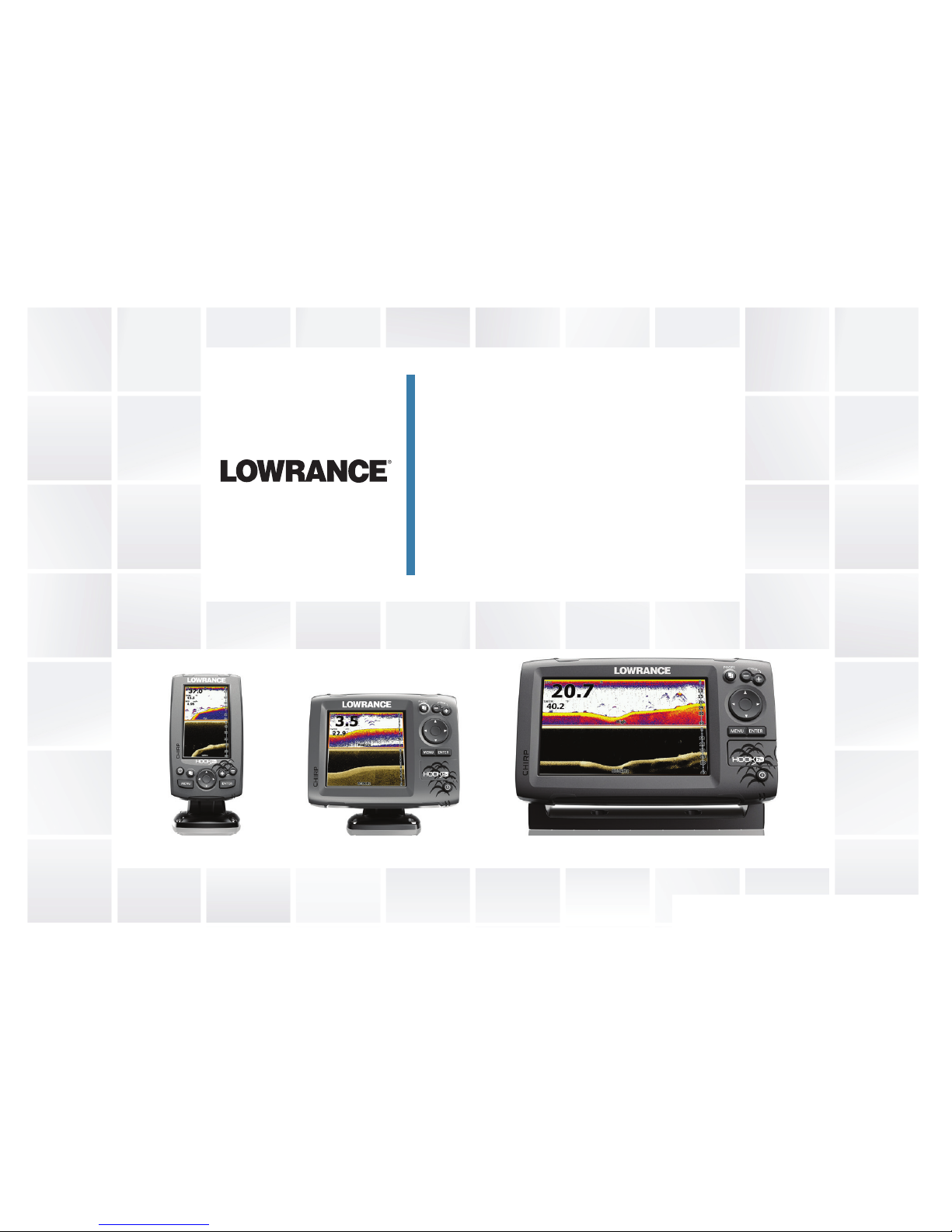
HOOK-X Series
Operation manual
HOOK-4x HOOK-5x HOOK-7x
Page 2

Copyright © 2016 Navico
All rights reserved.
Lowrance® and Navico® are registered trademarks of Navico.
Navico may nd it necessary to change or end our policies, regulations and special oers at any time.
We reserve the right to do so without notice. All features and specications subject to change without
notice.
Compliance Statements
Lowrance HOOK-4x, HOOK-5x and HOOK-7x
• meets the technical standards in accordance with Part 15.103 of the FCC rules
• complies with CE under EMC directive 2004/108/EC
• complies with the requirements of level 2 devices of the Radiocommunications (Electromagnetic
Compatibility) standard 2008
For more information please refer to our website: www.lowrance.com.
Page 3

Warning
The user is cautioned that any changes or modications not expressly approved by the party responsible
for compliance could void the user’s authority to operate the equipment.
This equipment has been tested and found to comply with the limits for a Class B digital device, pursuant
to Part 15 of the FCC rules. These limits are designed to provide reasonable protection against harmful
interference in a residential installation. This equipment generates, uses and can radiate radio frequency
energy and, if not installed and used in accordance with the instructions, may cause harmful interference
to radio communications. However, there is no guarantee that the interference will not occur in a particular
installation. If this equipment does cause harmful interference to radio or television reception, which can
be determined by turning the equipment o and on, the user is encouraged to try to correct the interference by one or more of the following measures:
• Reorient or relocate the receiving antenna
• Increase the separation between the equipment and receiver
• Connect the equipment into an outlet on a circuit different from that of the receiver
• Consult the dealer or an experienced technician for help
NOTE: This manual covers HOOK-4x, HOOK-5x and HOOK-7x units. As a result, screenshots of menus
and dialogs may not match the look of your unit.
Page 4

4
Table of contents | HOOK X series
Introduction ...................................... 6
Unit controls.............................................6
Basic operation................................ 7
Setup wizard ............................................7
Pages ......................................................7
Selecting pages ....................................... 7
Page menus ............................................7
Accessing the Settings menu ..................8
Accessing menu items.............................8
Working with menus ................................9
Dialogs.....................................................9
Fishing modes .......................................10
Cursor .................................................... 11
Advanced mode .................................... 11
Restore defaults .................................... 11
Pages .............................................. 12
Sonar page ............................................ 12
DownScan page ...................................12
Combo pages ........................................13
Overlay data ..........................................14
Sonar operation ............................. 15
CHIRP ...................................................15
Trackback ..............................................16
Sonar menu ........................................... 16
Sensitivity ..............................................17
Table of contents
Page 5

5
Table of contents | HOOK X series
Colorline ................................................17
Range .................................................... 17
Frequency .............................................18
Ping speed.............................................19
Fish ID ..................................................20
DownScan options.................................20
Sonar settings........................................22
Installation .............................................23
DownScan operation ..................... 25
Trackback .............................................25
DownScan menu ...................................25
Ping Speed ............................................ 27
DownScan options.................................27
Settings .......................................... 30
Settings menu........................................30
System...................................................30
Set language .........................................31
Audio .....................................................31
Alarms ..................................................31
Units ......................................................32
NMEA 0183 (HOOK-5x and HOOK-7x
only) ....................................................... 32
Specications ................................ 33
Page 6
6
Introduction | HOOK X series
Getting started
Turn unit
on/off
To turn on/off the unit, press and
hold the LIGHT/POWER key for
three seconds.
Adjusting
the
backlight
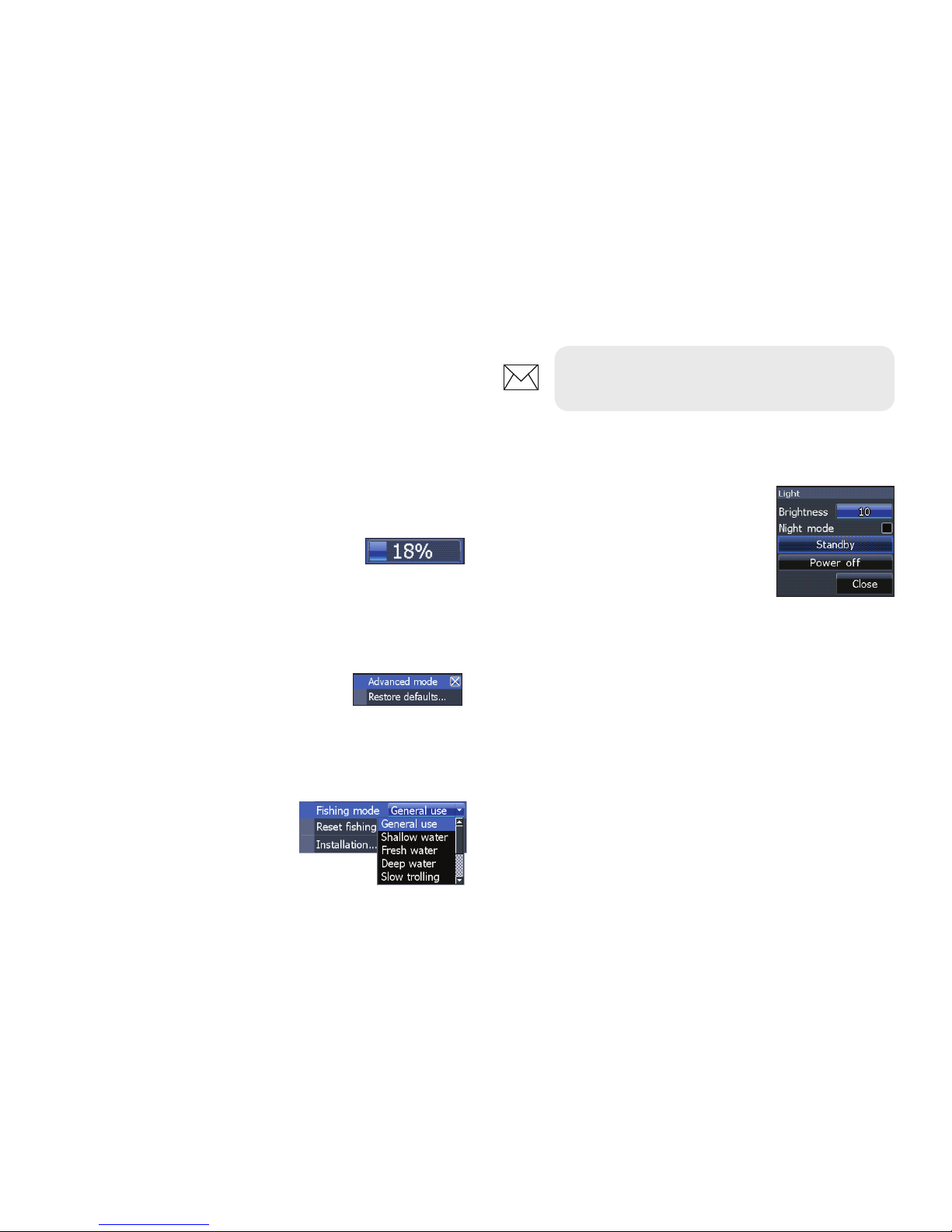
This unit has
10 backlight levels.
Press the LIGHT/POWER key to
switch backlight levels.
Muting
Audio
Select Audio from the System
menu and press ENTER. Enable/
disable Mute.
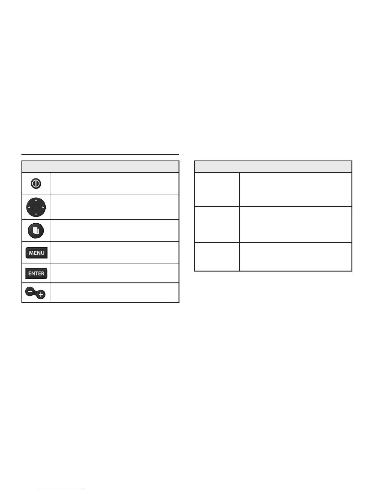
Unit controls
LIGHT/POWER: controls backlight
level and turns unit on/off
KEYPAD: controls cursor & selects
items on menus
PAGES: allows you to select a page to
view
MENU: opens settings, context and
page menus
ENTER: nalizes menu selections
ZOOM Keys: used to zoom in/zoom
out
Introduction
Page 7
7
Basic operation | HOOK X series
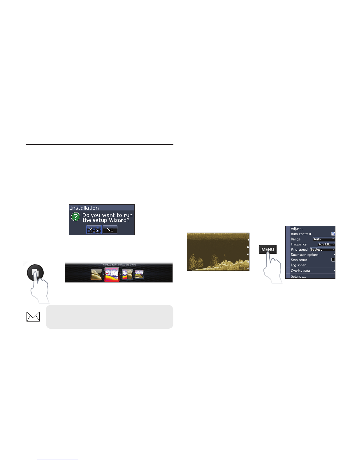
Selecting pages
To select a page, press the keypad in the direction
of the desired page and press ENTER.
Page menus
The DownScan and Sonar pages have menus
that can only be accessed when those pages are
displayed.
DownScan page
DownScan menu
Setup wizard
The Setup wizard will appear when the unit is
turned on for the rst time. To choose your own
settings, do not run the setup wizard. To restart
the Setup wizard, restore defaults.
Pages dialog
Pages
Basic operation
NOTE: Available pages vary depending
on the unit and the connected transducer.
Page 8
8
Basic operation | HOOK X series
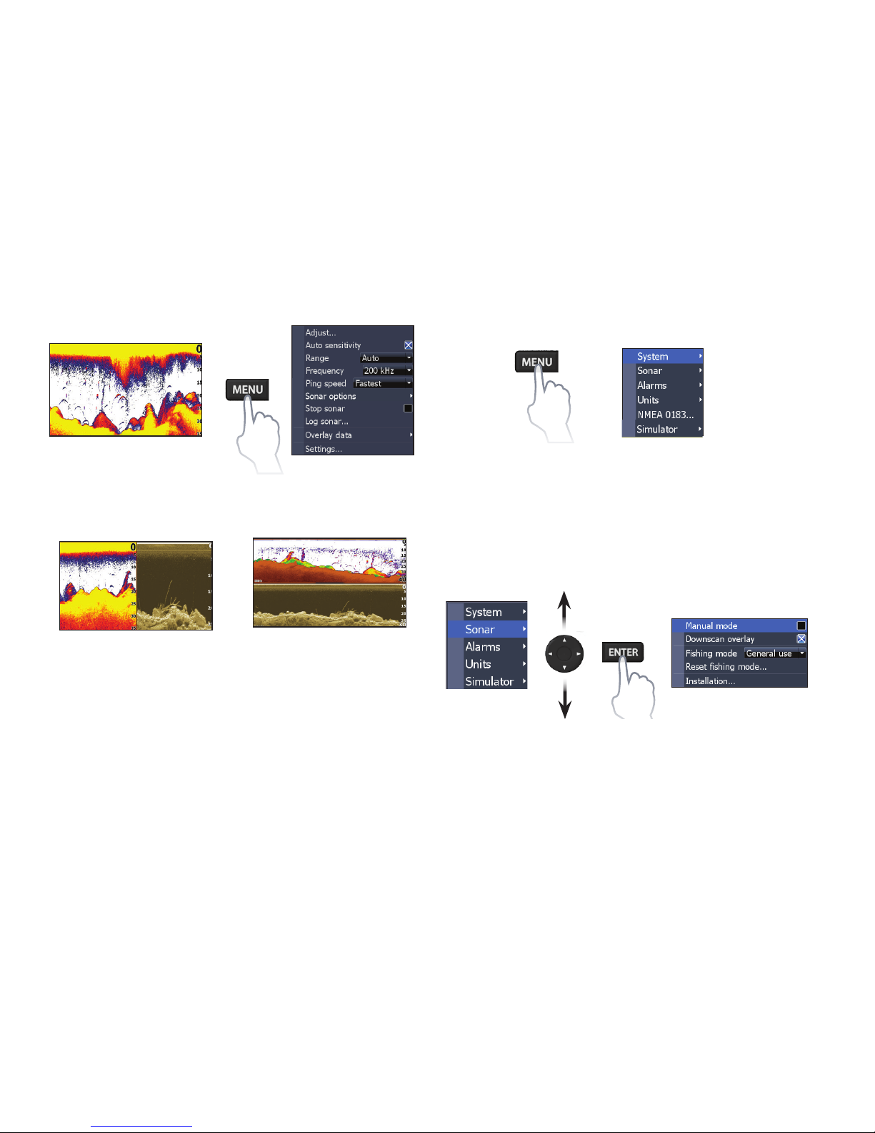
Combo pages
Press the PAGES key twice to switch active
panels. The page menu for active page will be
displayed when the MENU key is pressed. The
active panel is denoted by an orange border.
Accessing the Settings menu
Accessing menu items
The keypad and ENTER key are used to select
menu items and open submenus. Use the keypad
to highlight the desired item and press ENTER.
x2
Sonar page
Sonar menu
Two-panel page
Horizontal panel
Page 9
9
Basic operation | HOOK X series
Dialogs
Dialogs are used for user input
or for presenting information to
the user. Depending on the type
of entry, dierent methods are
used to conrm, cancel or close
the dialog.
Working with menus
There are several menu types used to make
adjustments to options and settings, including
scrollbars, on/o features and dropdown menus.
Scrollbars
Select the scrollbar and press the
keypad left (decrease) or right
(increase).
On/Off features
Select an on/o menu item and
press ENTER to turn it on/o.
Dropdown menus
Access the dropdown menu
and press use the keypad to
select the desired item and
press ENTER.
NOTE: Press the MENU key to Exit
menus.
Page 10
10
Basic operation | HOOK X series
Fishing mode options
General Use 1000 ft or less Coastal
Shallow
Water
60 ft or less Shallow weedy bottoms
Fresh Water 400 ft or less Inland/Near coastal
Deep Water 1000 ft or more Offshore
Slow
Trolling
400 ft or less Inland/Coastal
Fast
Trolling
400 ft or less Inland/Coastal
Clear Water 400 ft or less Inland/Coastal
Brackish
Water
400 ft or less Fresh-Saltwater mix
Ice 400 ft or less Ice shing
NOTE: Use Fresh Water mode when shing
in less than 100 feet of water; otherwise
your unit may not track bottom properly.
Fishing modes
(Conventional sonar only)
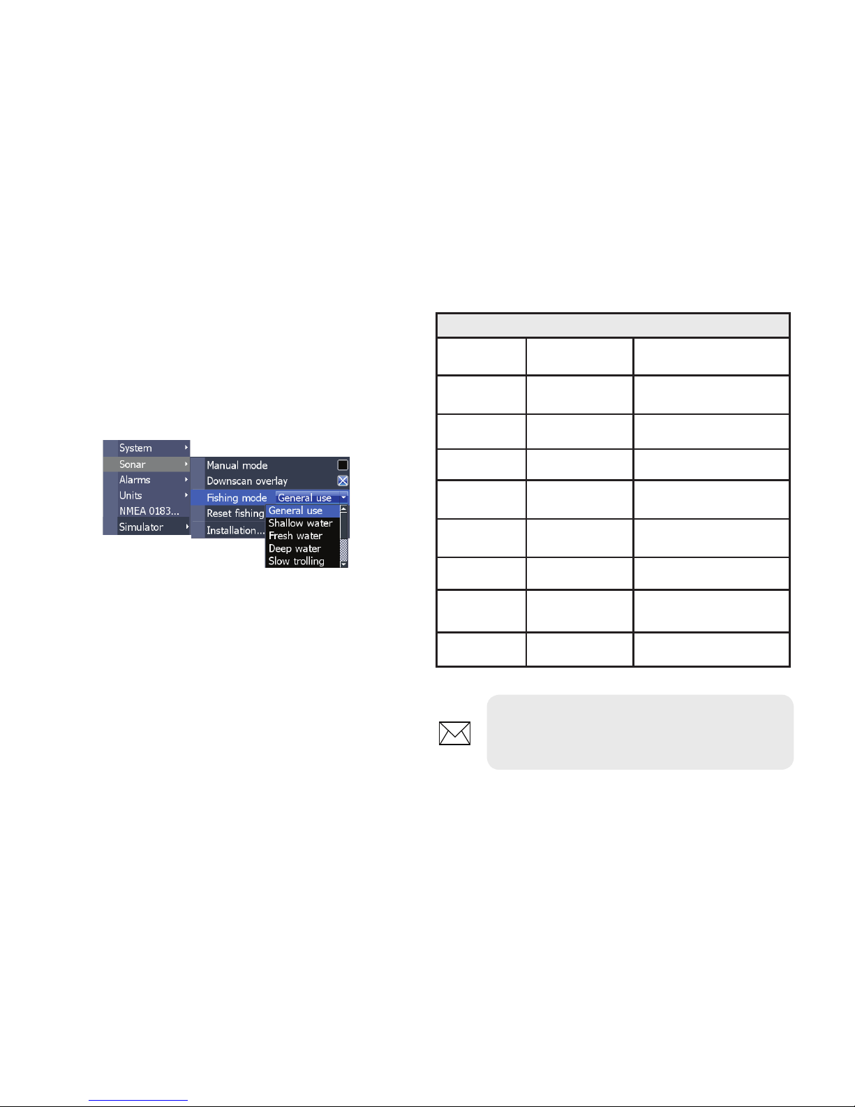
Fishing modes enhance the performance of your
unit by providing preset packages of sonar settings
geared to specic shing conditions.
Page 11
11
Basic operation | HOOK X series
Standby mode
Lowers power consumption by turning o sonar
and the display.
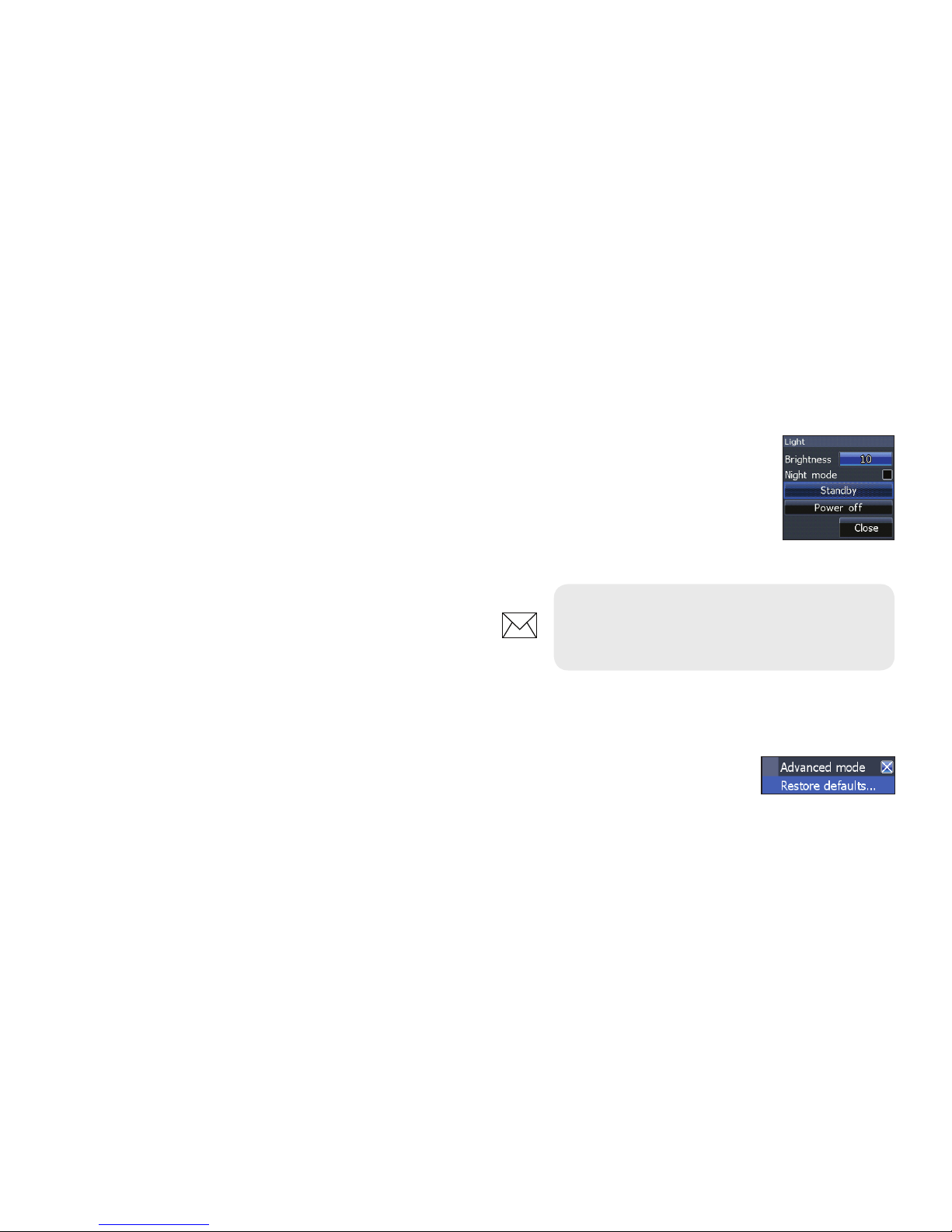
Press the PWR/LIGHT key to
access the Backlight dialog.
Select Standby and press ENTER.
Press any key to resume normal
operation.
Restore defaults
Resets unit options and settings
to defaults.
NOTE: Leaving your unit in Standby
mode when your boat is not is use will run
down your battery.
Cursor
The keypad moves the cursor around the display,
allowing you to scroll the map, select map items
and review sonar history.
Press MENU and select Return to vessel or Exit
cursor mode to clear the cursor.
Advanced mode
Enables advanced features and settings.
The following features are enabled when Advanced mode is turned on:
• Units (Enables distance, speed, depth,
temperature, and bearings options)
• HOOK-5x & HOOK-7x only:
NMEA 0183 Output (Requires optional
Power/NMEA cable 000-0127-49)
Page 12
12
Pages | HOOK X series
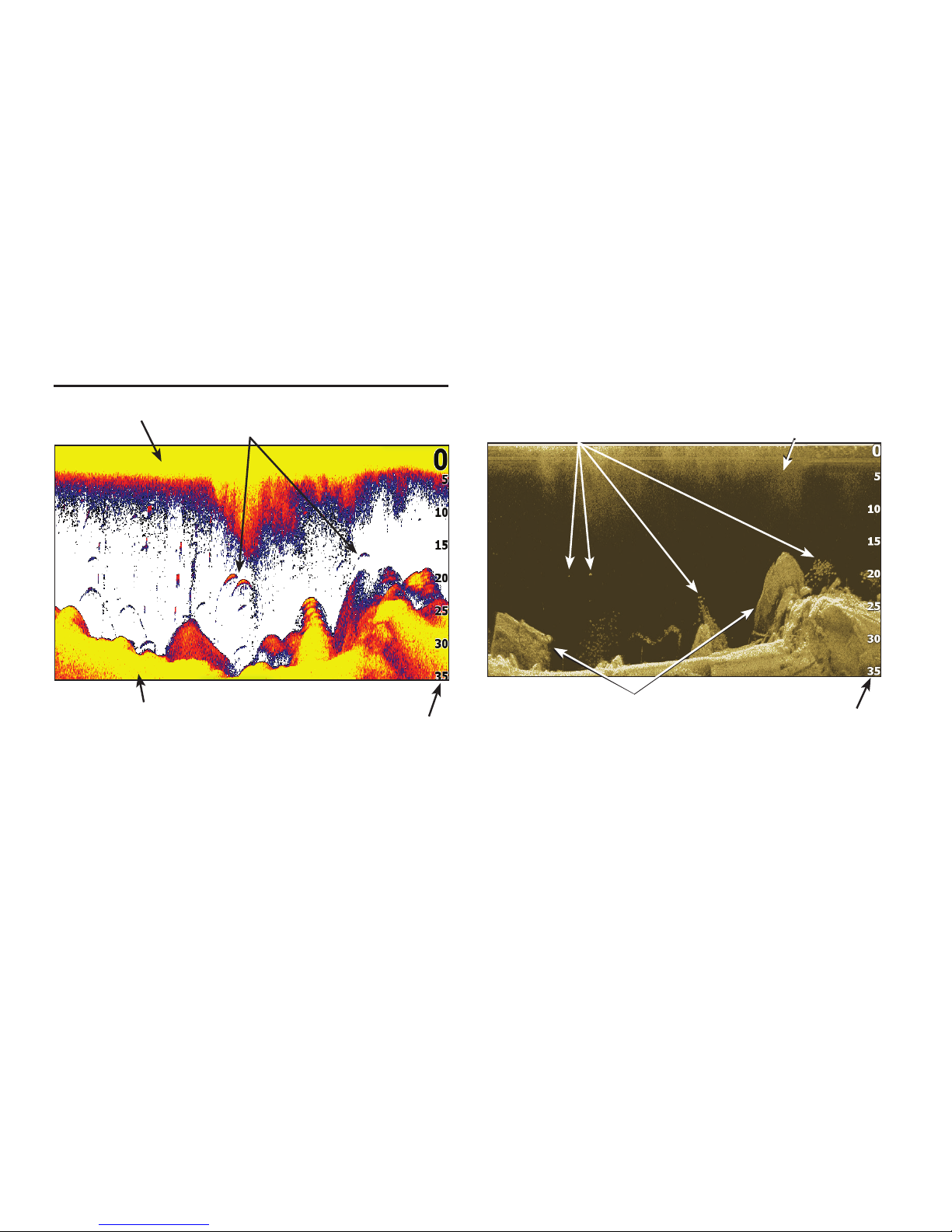
Sonar page
Displays the water column moving from right to
left on your unit’s screen.
Fish arches
Surface Clutter
Range scale
Bottom
Pages
DownScan page
The Downscan page shows the water column
moving from right to left. You can overlay
downscan sonar on the conventional sonar page
by selecting DownScan Overlay on the Sonar
settings menu.
Structure
Fish
Surface clutter
Range scale
Page 13
13
Pages | HOOK X series
Combo pages
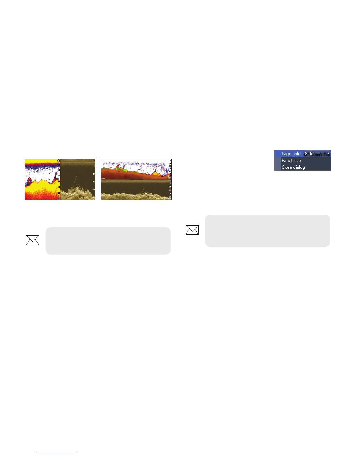
This unit has two pre-congured combo pages.
Sonar/DownScan Sonar/DownScan
horitzontal
NOTE: Press the PAGES key twice to
switch active panels.
Customizing combo pages
You can adjust the panel size of combo pages and
control how the pages will
be arranged on the screen:
vertically (side) or horizontally
(over).
To make adjustments to combo page panels,
select a combo page from the Pages carousel and
press MENU.
NOTE: To adjust panel size, access the
customize menu after selecting a combo
page for display.
Page 14
14
Pages | HOOK X series
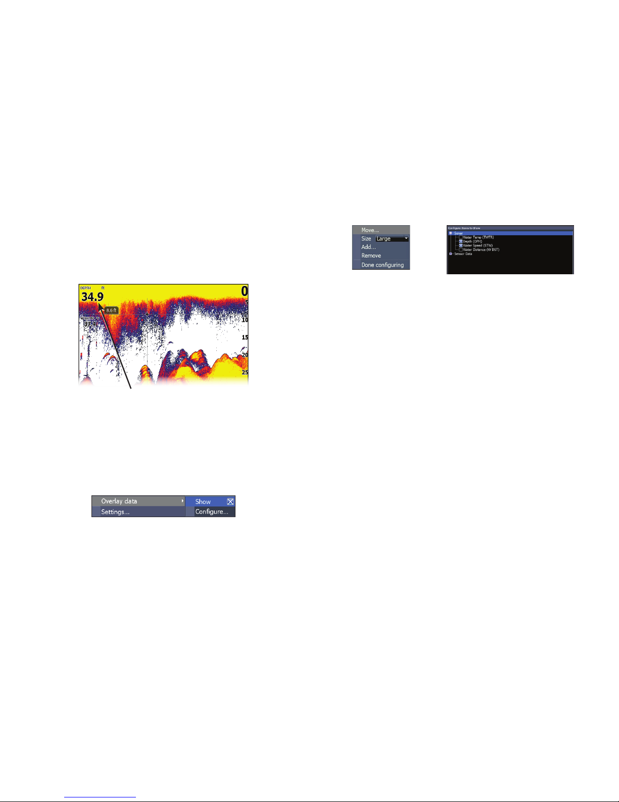
To add overlay data:
1. From the Sonar or DownScan page,
press MENU.
2. Select Overlay data and press ENTER.
3. Select Congure and press ENTER.
4. Press MENU and select Add. Press
ENTER.
5. Select a data category and press
ENTER.
6. Select the desired data and press
ENTER.
7. Press MENU and select Return to
Overlays. Press ENTER.
8. Press MENU, select Done conguring
and press ENTER.
Overlay data
Used to select data shown on the Sonar and Structure pages.
Show
Enables/disables the display of overlay data,
allowing you to remove overlay data from the
screen without deleting the current overlay data
conguration.
Congure
Allows you to select/customize overlay data.
Overlay data
Page 15
15
Sonar operation | HOOK X series
CHIRP
A CHIRP (Compressed High Intensity Radar Pulse)
transducer transmits a modulated pulse of all
frequencies within the bandwidth of the selected
transducer type.
This results in better image quality, better target
separation and greater depth penetration.
This unit supports High CHIRP, Medium CHIRP
and Low CHIRP, depending on the transducer.
CHIRP can be used with Lowrance conventional
sonar transducers.
• 50/200 kHz (Low/High CHIRP)
• 83/200 kHz (Medium/High CHIRP)
To use CHIRP, select the desired CHIRP frequency
from the Frequency menu.
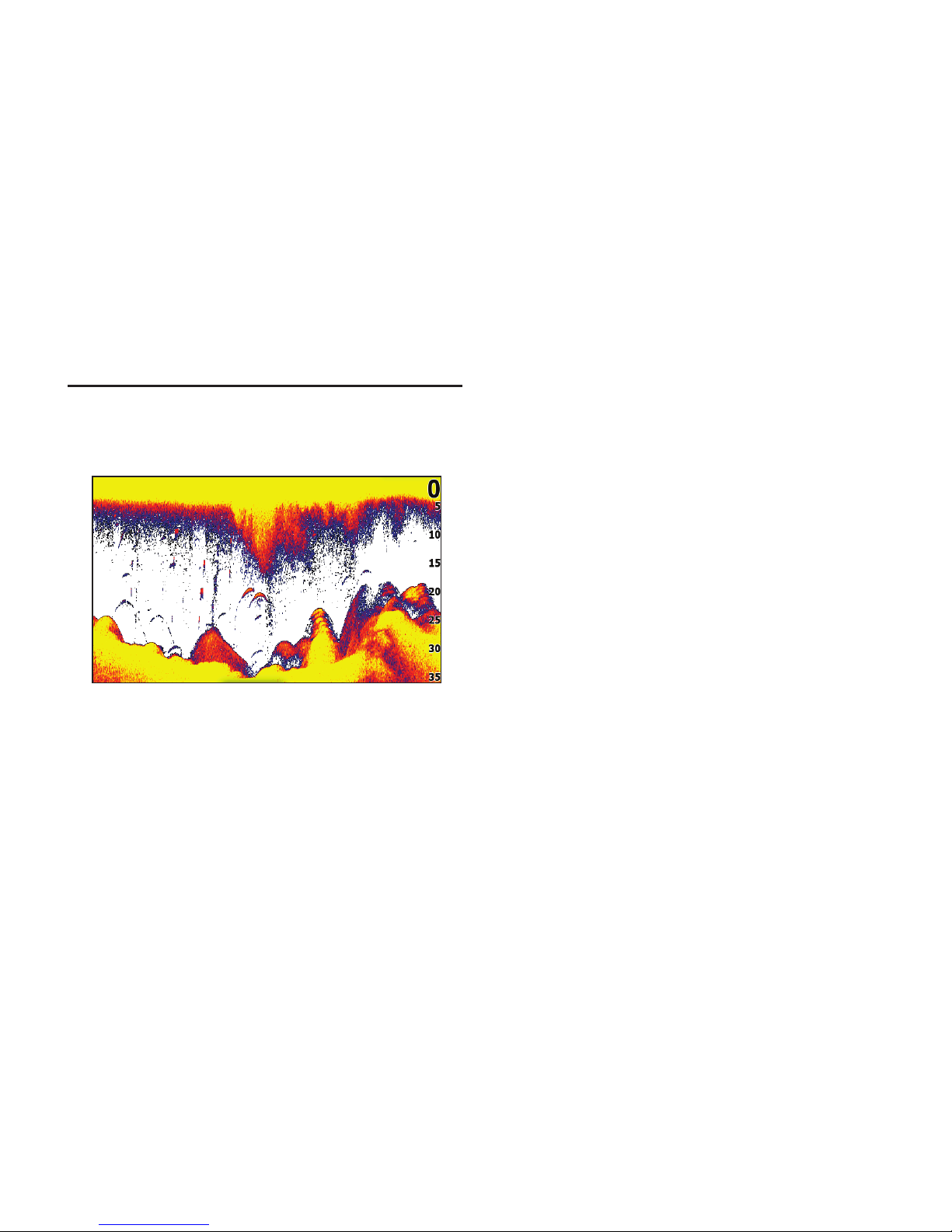
This unit supports two types of sonar: Conventional
and DownScan.
The features described in this section are for
conventional sonar. Refer to the DownScan
operation section for information on DownScan
features.
Sonar operation
Page 16
16
Sonar operation | HOOK X series
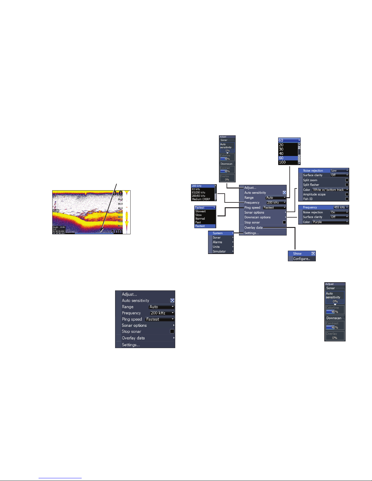
Blue sonar history bar
Trackback
You can review your recent sonar history by moving the cursor to the left until the screen starts to
move in reverse.
Move the sonar history bar all the way to the right
to resume normal sonar scrolling, or press MENU
and select Exit cursor mode.
Sonar menu
Press MENU from any sonar
page to access the Sonar
menu.
Adjust
Used to make adjustments to Sensitivity
and Colorline/Grayscale.
Sonar menu
(Advanced mode)
(Only active with
Downscan overlay
turned on)
Page 17
17
Sonar operation | HOOK X series
Sensitivity
Controls the level of detail shown on the display.
Too much detail will clutter the screen. If Sensitivity is set too low, desired echoes may not be
displayed.
Colorline
Helps distinguish sh or structure from the
bottom by showing hard returns as light colors
and soft returns as darker colors. A lower colorline
setting will display only the hardest returns,
shown in light colors.
Auto sensitivity
Keeps sensitivity at a level that works well under
most conditions, reducing the needs for adjustments. Auto Sensitivity is turned on by default.
NOTE: You can make minor (+/-40%)
changes to sensitivity with Auto
Sensitivity turned on. You will have to turn
it o to make signicant adjustments.
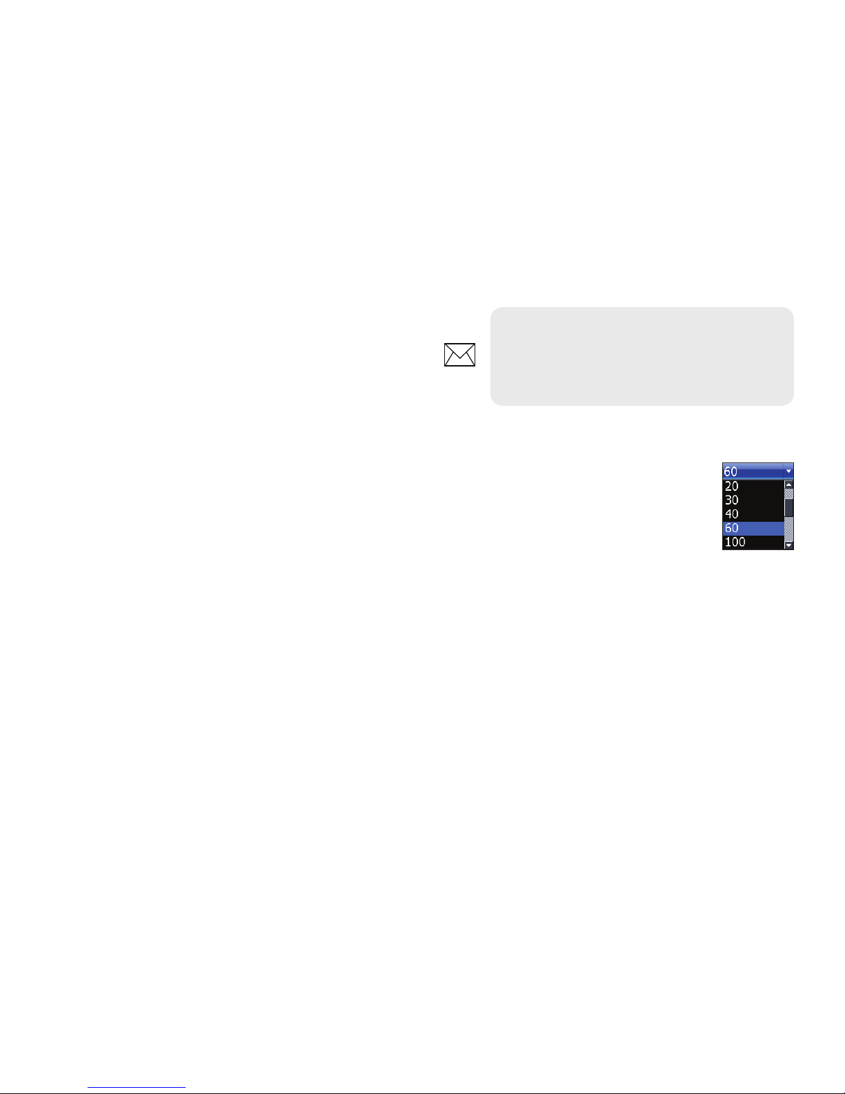
Range
Selects the deepest range shown on
the display. Range settings display
the section of the water column from
the water surface to the selected
depth range.
If you select too shallow a depth range, the unit
will not be able to lock onto the bottom.
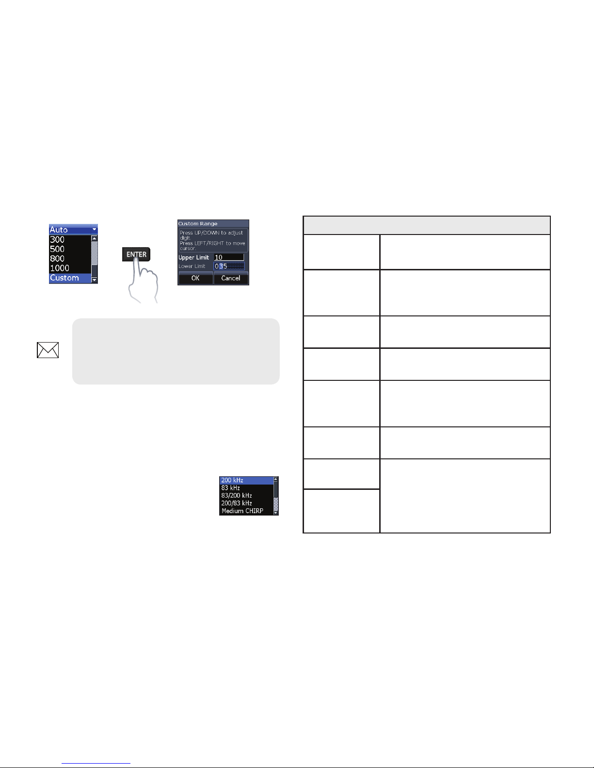
Custom range — Upper and Lower limits
Used to select the upper limit and lower limit of
a section of the water column. That allows you to
view a section of the water column that does not
include the water surface or the bottom. Upper
and lower limits must be at least 6.5 ft (2 m) apart.
Page 18
18
Sonar operation | HOOK X series
Frequency
Controls the transducer frequency used by the
unit. This unit supports conventional, CHIRP and
DownScan sonar frequencies.
Only frequencies supported by
your transducer will appear on the
Frequency menu.
Custom range menu
NOTE: When using a custom range,
you may not receive any digital depth
readings, or you may receive incorrect
depth information.
Sonar frequencies
50 kHz
Best depth penetration with
lower resolution
83 kHz
Wider cone angle provides more
bottom coverage and easy lure
tracking
200 kHz
Highest sensitivity and best target separation in shallow water
Low CHIRP
Provides the best depth penetration with lower resolution
Medium
CHIRP
Better depth penetration than
High CHIRP with minimal loss of
target separation
High CHIRP
Better resolution in shallow
water than Medium CHIRP
Custom high
Selects a custom single
frequency from within High or
Low frequency ranges to help
reduce/eliminate interference
from other CHIRP transducers
Custom
medium
Page 19
19
Sonar operation | HOOK X series
Ping speed
Controls the rate the transducer uses to send sonar waves into the water. Ping speed adjustments
can help reduce interference from other transducers. When using shing modes, ping speed
settings are optimized for the selected shing
conditions, so in most cases, adjustments are not
necessary.
Sonar options
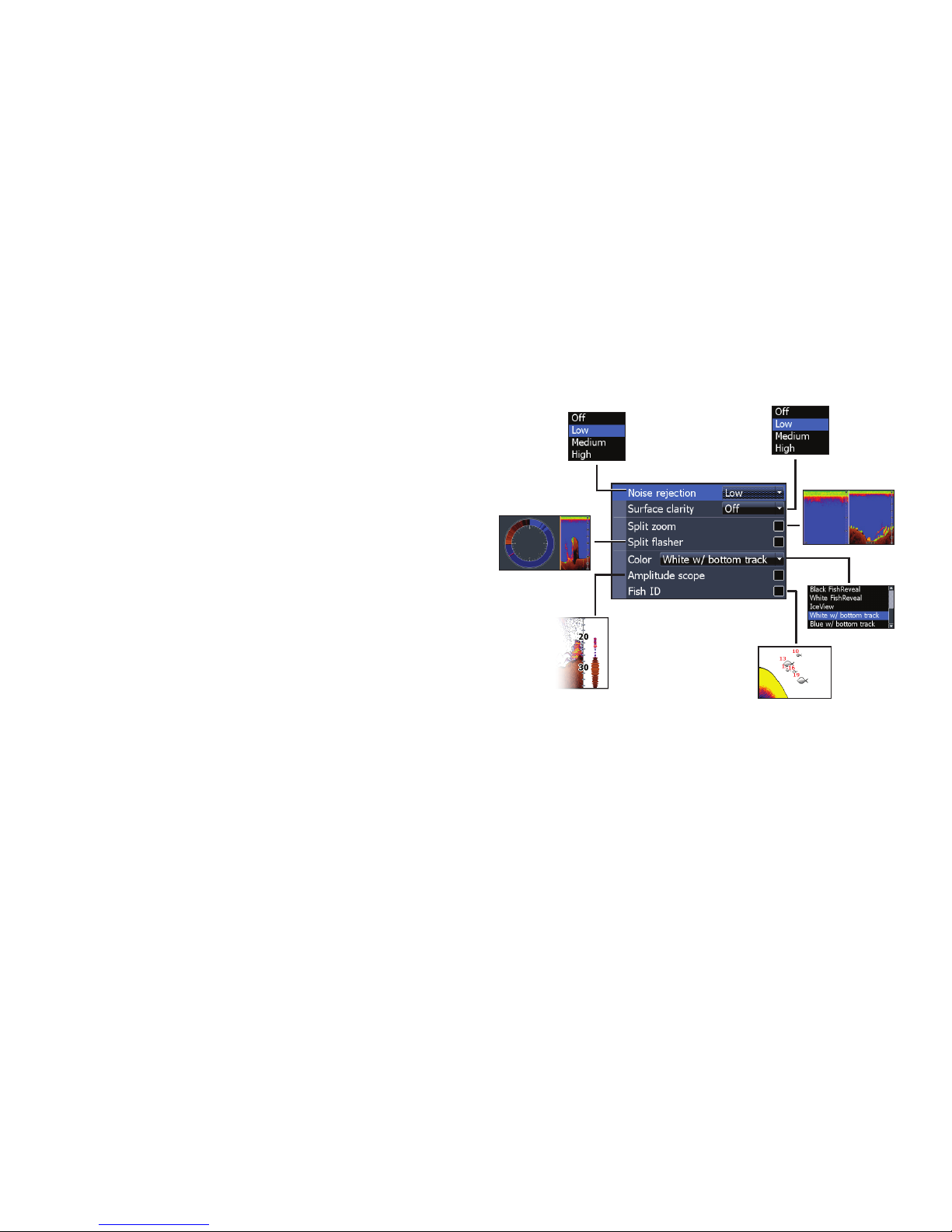
Noise rejection
Uses advanced signal processing to monitor the
eects noise (boat pumps, water conditions,
engine ignition systems, etc.) has on your display,
and then lters out undesired signals.
Page 20
20
Sonar operation | HOOK X series
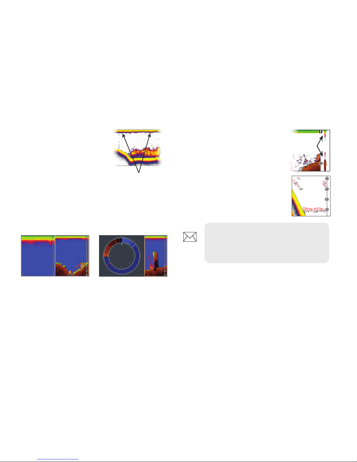
Amplitude scope
Displays the amplitude of the
most recent echo.
Fish ID
Displays sh echoes as sh symbols instead of sh arches.
NOTE: Fish ID is not the most accurate
method of sh detection since structure
and suspended debris may be shown as
a sh symbol on the display.
DownScan options
You can make adjustments to DownScan overlay
settings from the sonar page. DownScan options
are covered in more detail in the DownScan
operation section.
Amplitude
scope
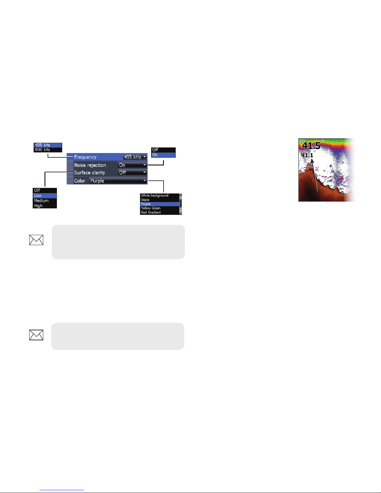
Surface clarity
Surface Clarity reduces
surface clutter by
decreasing the sensitivity
of the receiver near the
surface.
Split zoom and Split asher
Switches the sonar display from full screen sonar
to a split screen view.
Color
Allows you to change the look of the display using
palettes with varying degrees of color/brightness.
Split zoom Split asher
Surface Clutter
Page 21
21
Sonar operation | HOOK X series
Stop sonar
Prevents the transducer from transmitting to
reduce/eliminate interference between two sonar
units running on the boat at the same time.
Overlay data
Allows you to select data to
be displayed on top of the
Sonar page.
Overlay data setup is covered
in the Pages section.
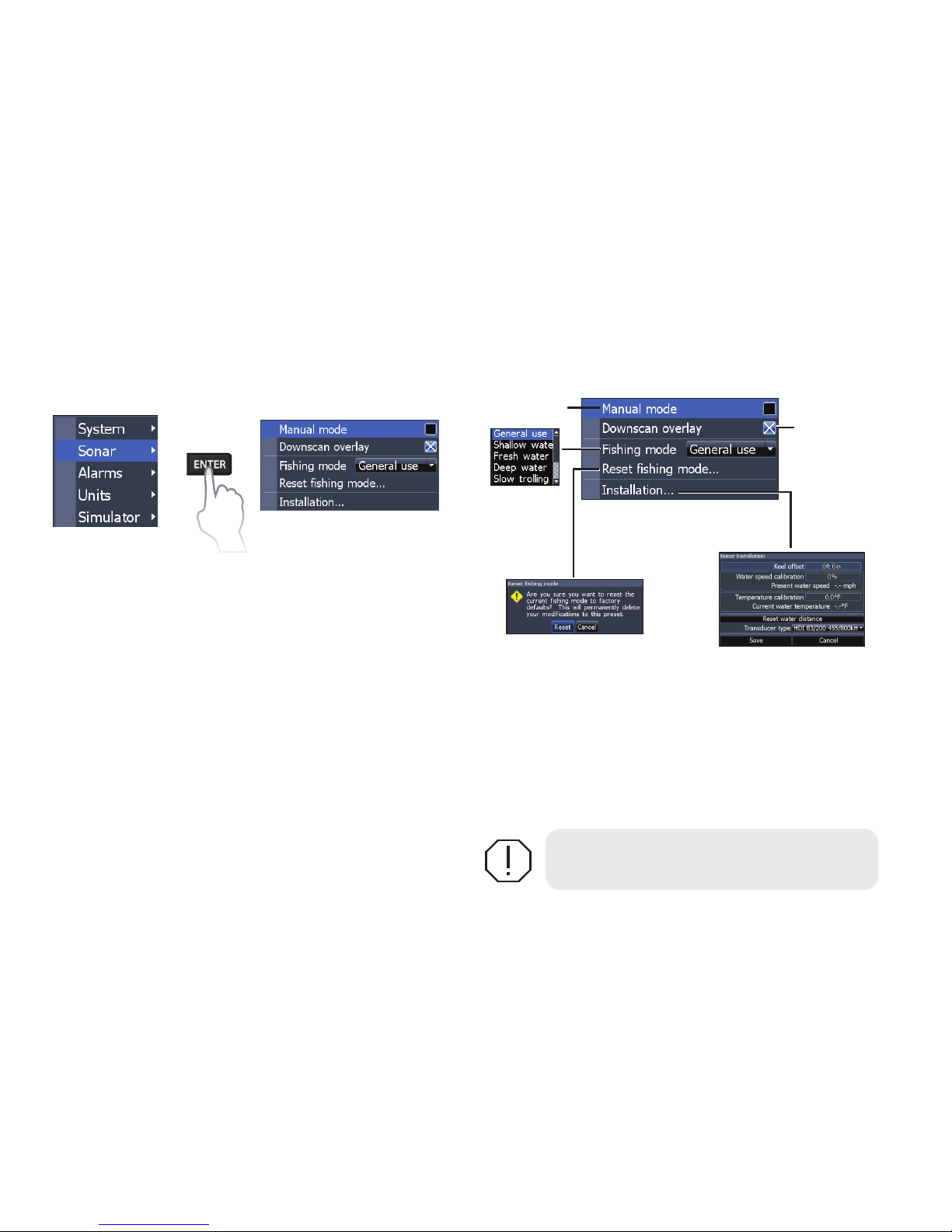
NOTE: The DownScan options menu
will only be available when DownScan
overlay is enabled.
DownScan options menu
NOTE: Sonar history will not be
recorded when sonar is stopped.
Overlay data
Page 22
22
Sonar operation | HOOK X series
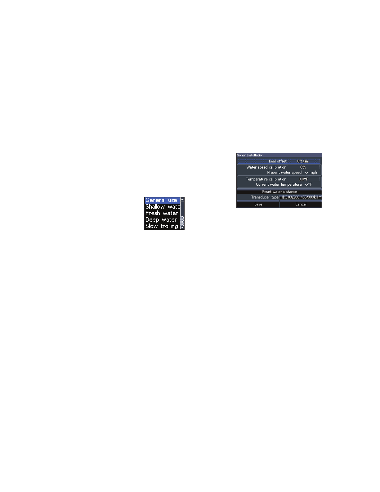
Sonar settings
Conventional settings/DownScan settings
You can adjust settings for both Conventional
sonar and DownScan sonar modes from the Sonar
Settings menu.
Only adjustments made to conventional sonar
settings will be visible on the sonar page.
WARNING: Manual mode should only
be used by advanced sonar users.
Manual mode
Restricts digital depth capability, so the unit will
only send sonar signals to the selected depth
range. That allows the display to continue smooth
scrolling if the bottom depth is out of transducer
range.
Sonar Settings Menu
Restricts
unit’s digital
depth search
capability
Turns on/off
Dowsncan
overlay
display
Page 23
23
Sonar operation | HOOK X series
When the unit is in manual mode, you may not
receive any depth readings, or you may receive
incorrect depth information.
Fishing mode
Enhances the performance of your
unit by providing preset packages
of sonar settings geared to specic
shing conditions. For more
information about shing modes,
refer to the Basic Operation section.
Reset shing mode
Resets selected shing mode to default settings.
That is useful when you want to clear settings
adjustments made while using a shing mode.
Installation
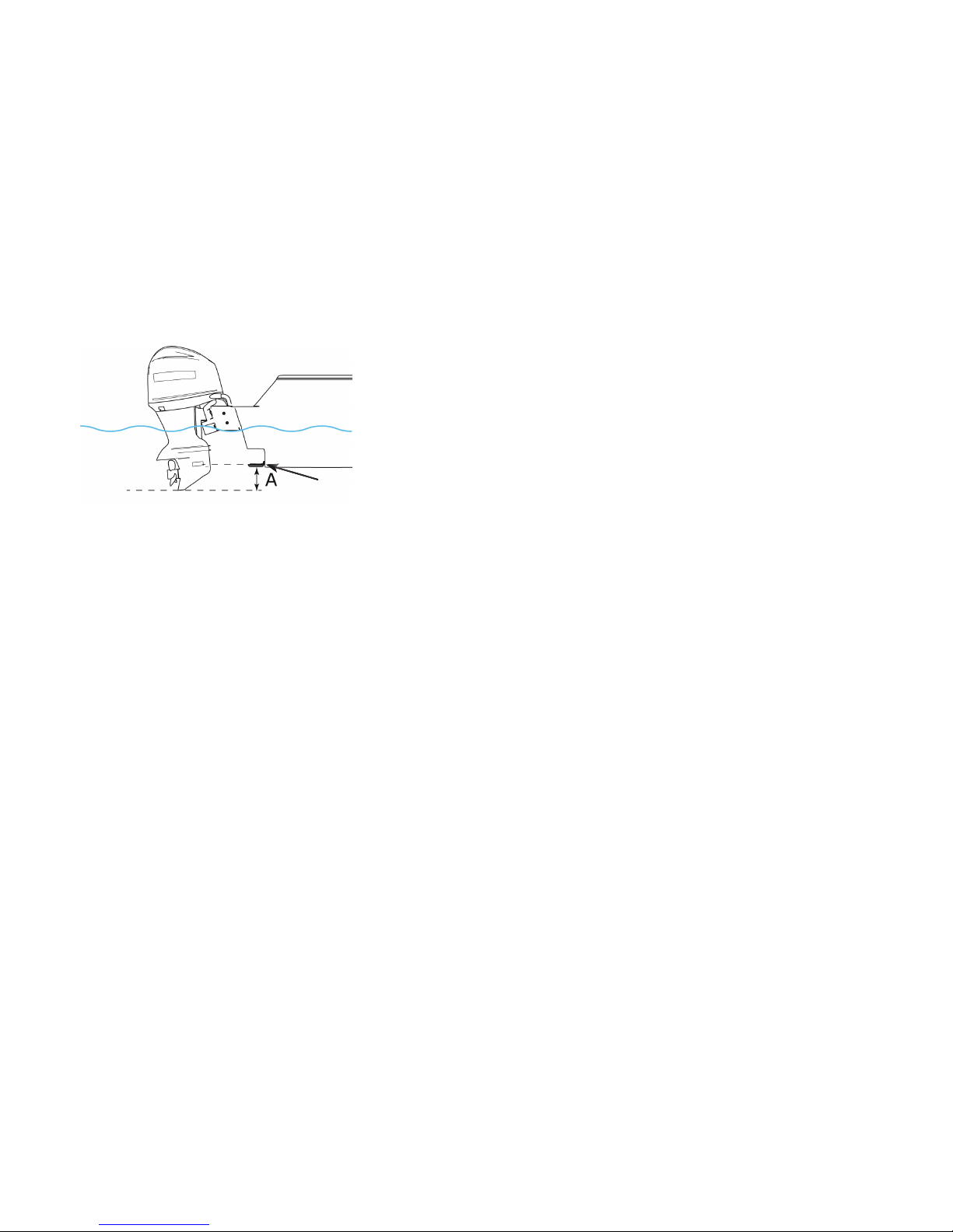
Keel offset
All transducers measure water depth from the
transducer to the bottom. As a result, water depth
readings do not account for the distance from
the transducer to the keel/bottom of motor or
from the transducer to the water surface. Before
setting keel oset, measure the distance from
the transducer to the bottom of the motor - see
illustration next page.
Installation menu
Page 24
24
Sonar operation | HOOK X series
Transducer
A: Keel offset (e.g. -1 foot)
If, for example, the distance is 1 foot, it will be
input as (minus) –1 foot.
Water speed calibration
Calibrates a paddlewheel speed sensor.
Temperature calibration
Calibrates data from the transducer temperature
sensor with data from a known temperature source
to ensure the accuracy of temperature information.
Reset water distance
Reset Water Distance to zero.
Transducer type
Selects the type of transducer model attached to
your unit.
Page 25
25
DownScan operation | HOOK X series
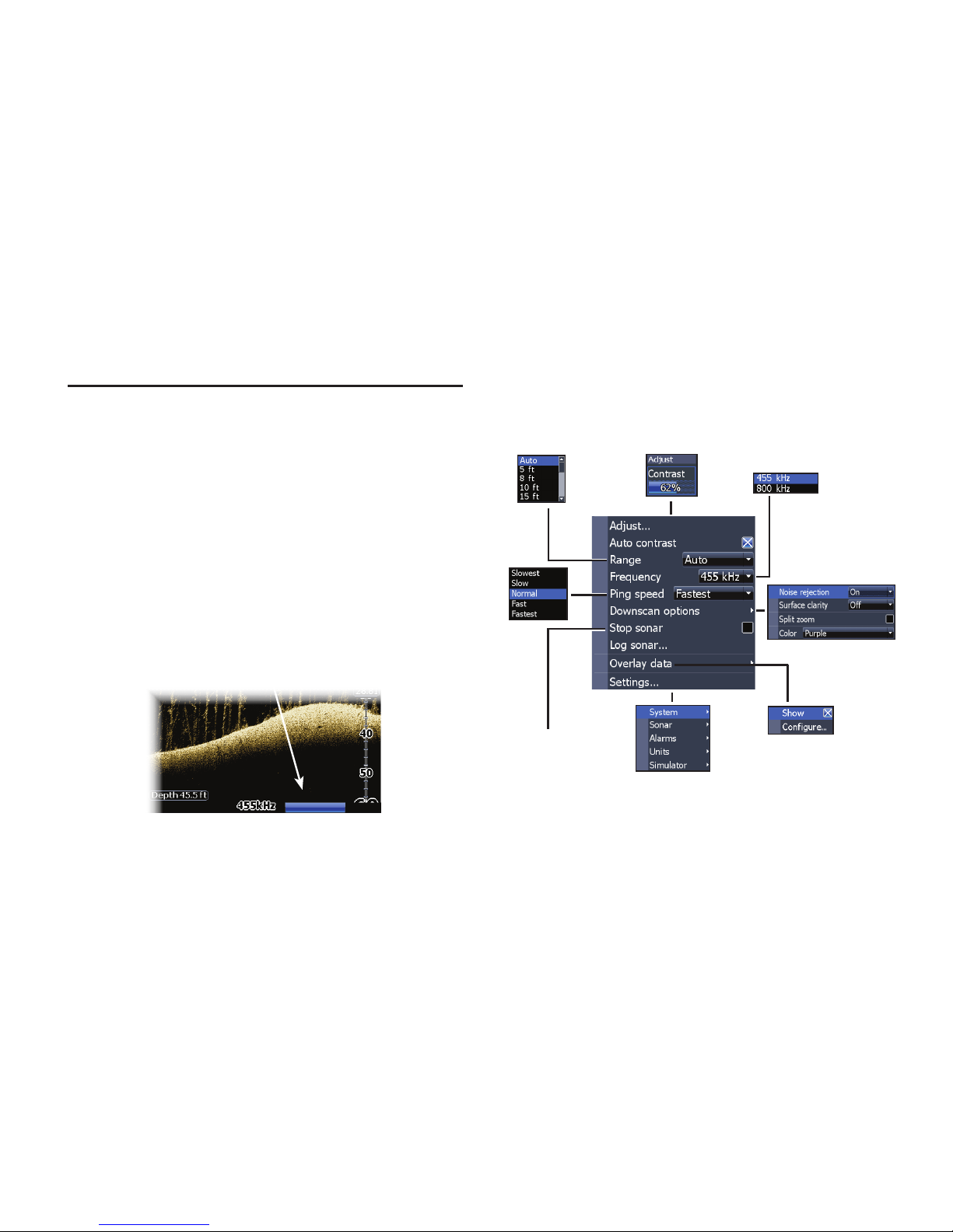
Features described in this section are for
DownScan sonar. Refer to the Sonar operation
section for information on conventional sonar.
Trackback
You can review your sonar history by pressing the
keypad to the left until the screen starts to move
in reverse and the sonar history bar appears at the
bottom of the screen.
Move the sonar history bar all the way to the right
to resume normal sonar scrolling, or press MENU
and select Exit cursor mode.
DownScan menu
Press MENU from the DownScan page to view the
DownScan menu.
DownScan operation
Stops sonar
transmission;
pauses sonar scroll
DownScan history bar
Page 26
26
DownScan operation | HOOK X series
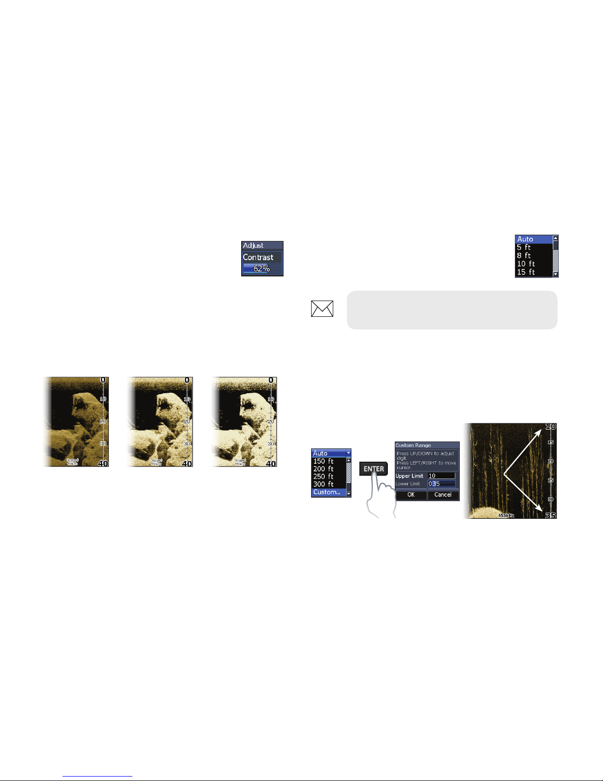
Custom range — Upper and Lower limits
Used to select the upper limit and lower limit of
a section of the water column. That allows you to
view a section of the water column.
Upper and lower limits must be at least 6.5 ft (2 m)
apart.
Contrast
Adjusts the brightness ratio between light and
dark areas on the screen, making it easier to distinguish suspended objects from the background.
Adjust
Accesses the Contrast adjustment
scrollbar, allowing you to adjust
contrast settings.
Range
Range settings display the section
of the water column from the water
surface to the selected depth range.
Contrast set
to 40
Contrast set
to 60
Contrast set
to 80
NOTE: Auto range is the preferred
setting for most shing conditions.
Page 27
27
DownScan operation | HOOK X series
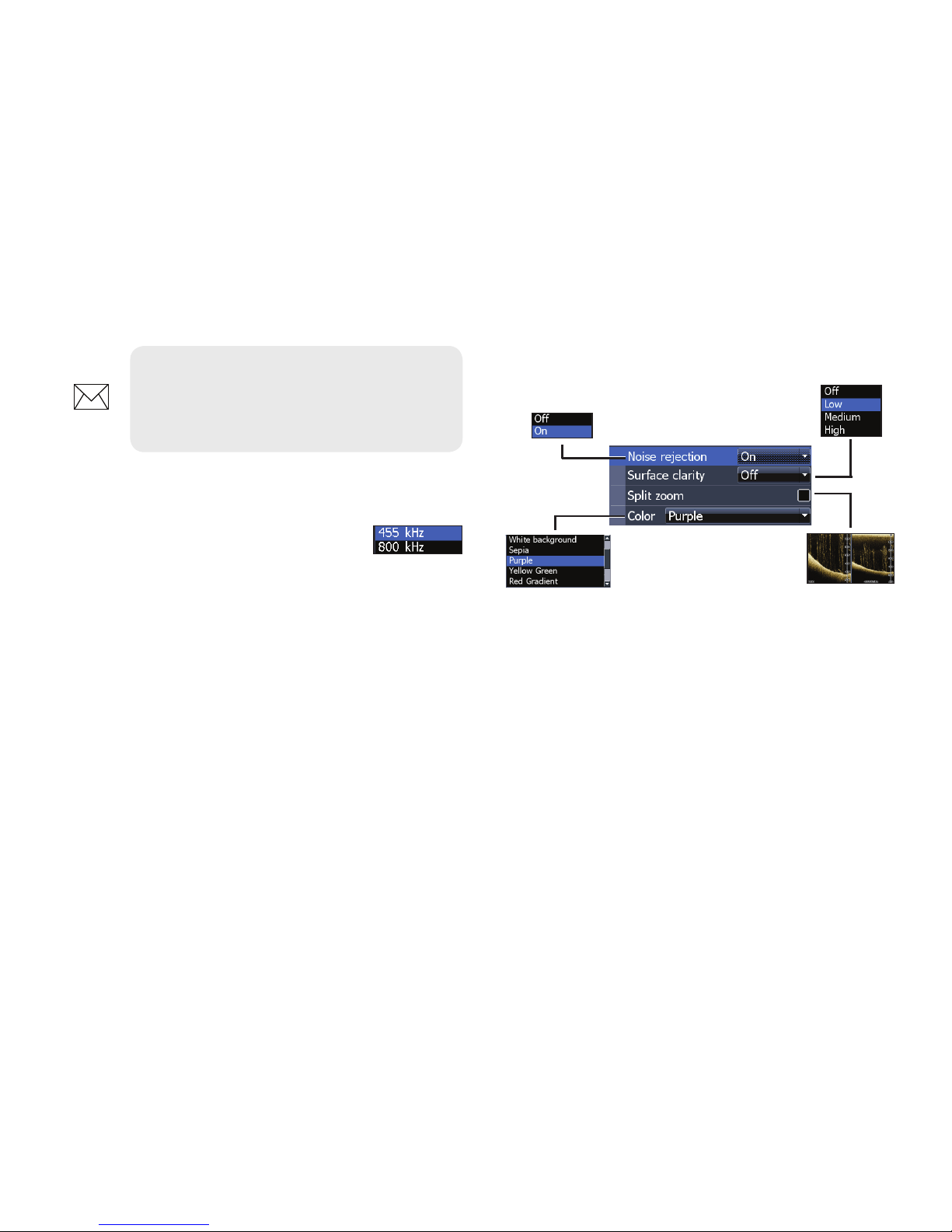
Frequency
Controls the transducer frequency
used by the unit. 800 kHz oers the
best resolution, while 455 kHz has
greater depth penetration.
NOTE: When using a custom range,
you may not receive any digital depth
readings, or you may receive incorrect
depth information.
Ping Speed
Controls the rate the transducer uses to send sonar
waves into the water. Ping speed adjustments can
help reduce interference from other transducers.
DownScan options
Noise Rejection
Uses advanced signal processing to monitor the
eects noise (boat pumps, water conditions,
engine ignition systems, etc.) has on your display,
and then lters out undesired signals.
Page 28
28
DownScan operation | HOOK X series
Stop sonar
Prevents the transducer from transmitting to
reduce/eliminate interference between two sonar
units running on the boat at the same time.
NOTE: Sonar history (Trackback) will
not be recorded when sonar is stopped.
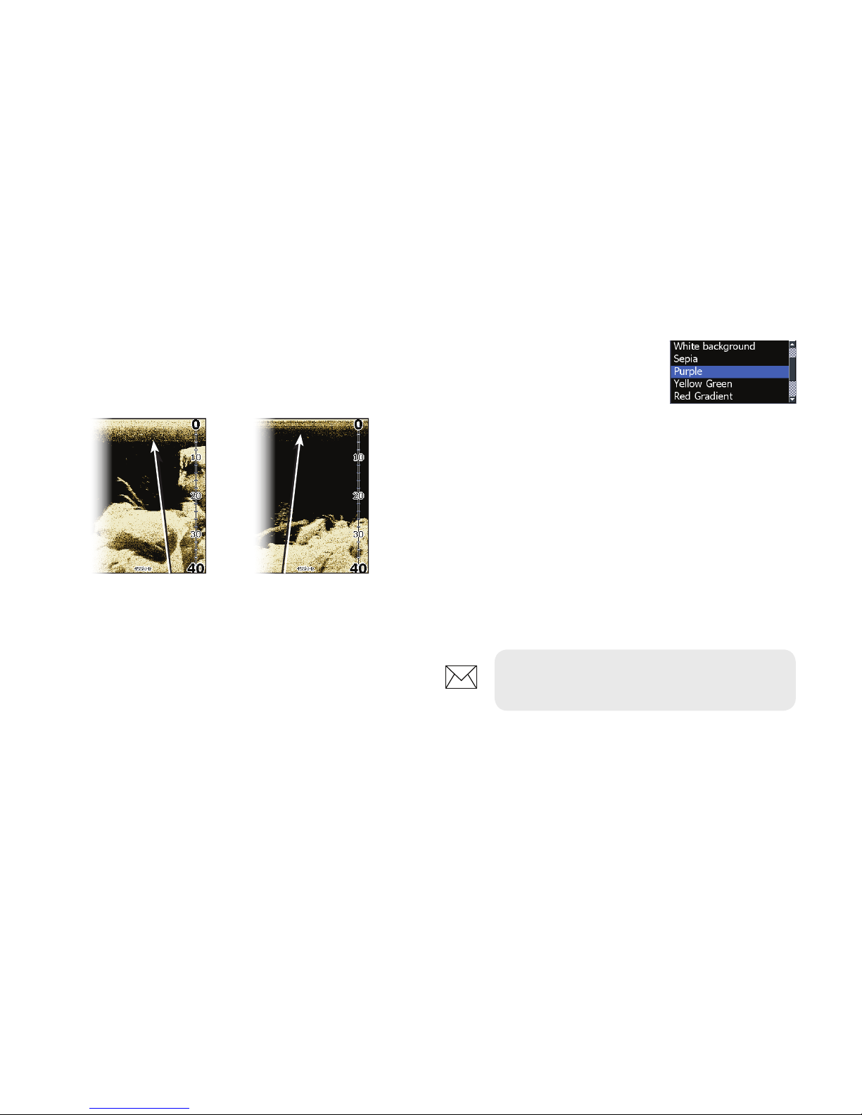
Split zoom
Changes the display to a split zoom view.
Surface clarity
Surface Clarity reduces surface clutter by
decreasing the sensitivity of the receiver near
the surface.
Surface clarity
set to Low.
Surface clarity
set to High.
Color
Allows you to select a color
palette best suited to your
shing conditions.
The white background palette works well for
suspended targets. Purple is useful for viewing
structure detail and determining bottom
hardness. Sepia is best for looking at bottom
detail.
Page 29

29
DownScan operation | HOOK X series
Overlay data
Allows you to select data to
be displayed on top of the
DownScan page.
Overlay data setup is covered
in the Pages section.
Settings
Accesses the Settings menu. Refer to “Sonar
settings” on page 22.
Overlay data
Page 30
30
Settings | HOOK X series
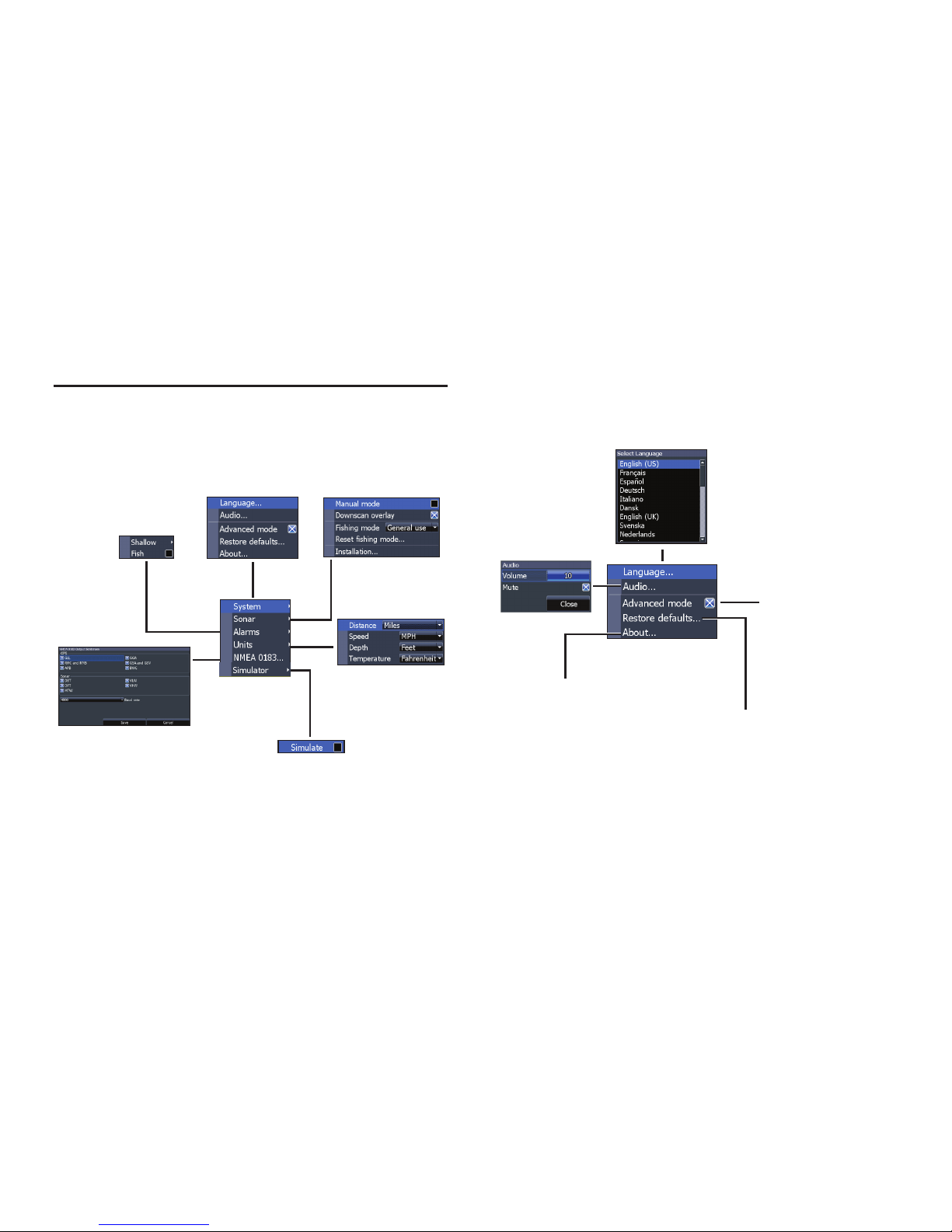
Settings menu
Accesses installation and conguration settings for
your unit.
Settings
menu
(Advanced mode
only, HOOK-5x &
HOOK-7x)
(Advanced mode
only)
System
Adjusts unit settings like language, mute audio
and advanced mode.
Enables
advanced
features.
Refer to “Advanced mode”
on page 11.
Displays software
information
System menu
Restores settings
and options to factory default settings
Settings
Page 31
31
Settings | HOOK X series
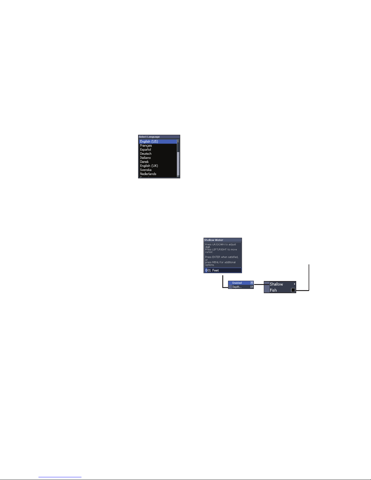
Set language
Selects the language used on
menus and dialogs.
Audio
Adjusts volume and turns on/o unit audio, like
key beeps, alarm sounds, etc.
Advanced mode
Enables features and settings only available with
unit in Advanced mode.
Restore defaults
Switches the unit back to default settings.
About
Displays software information about this unit.
Before attempting a software update, you can
check the version of software your unit is using by
accessing the About screen.
Lowrance periodically updates unit software to
add features and improve functionality.
To see the latest available software version go to
www.lowrance.com.
Alarms
Enables alarms and selects alarm thresholds.
Alarms
menu
Sounds alarm when
Fish ID symbol
appears on display
Page 32
32
Settings | HOOK X series
NMEA 0183 (HOOK-5x and HOOK-7x only)
(optional Power/NMEA cable 000-0127-49)
You can select the NMEA 0183 sentences the unit
will use when connected a NMEA 0183 device.
You can also adjust the Baud rate.
Simulator
Simulates sonar activity.
Alarms
Shallow
Sounds alarm when vessel enters water
shallower than the selected shallow
threshold
Fish
Sounds alarm when a sh symbol (Fish ID)
appears on the sonar screen
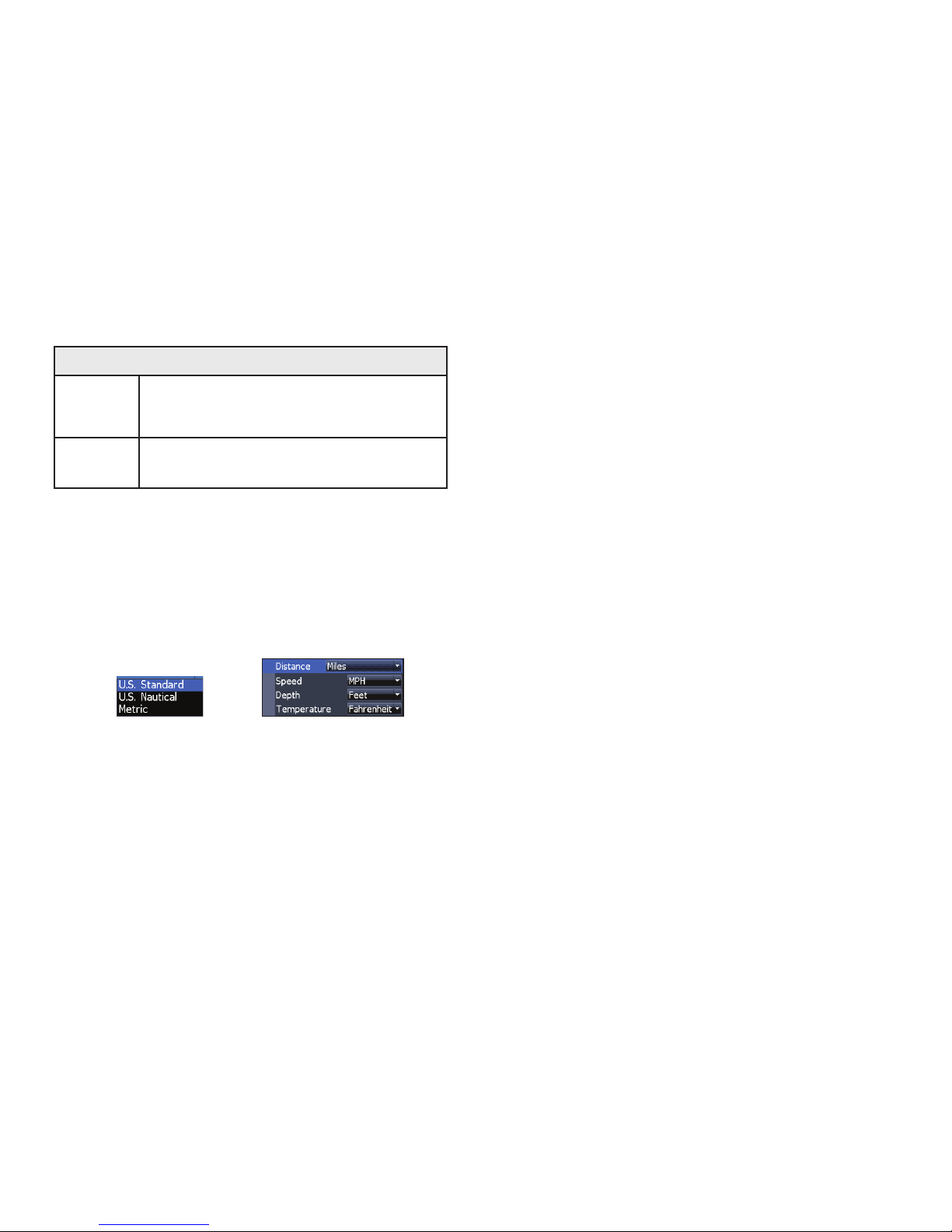
Units
Allows you to select the unit of measure used by
the unit. Unit options vary depending on whether
the unit is in basic or advanced mode.
Advanced Mode
Basic Mode
Page 33
33
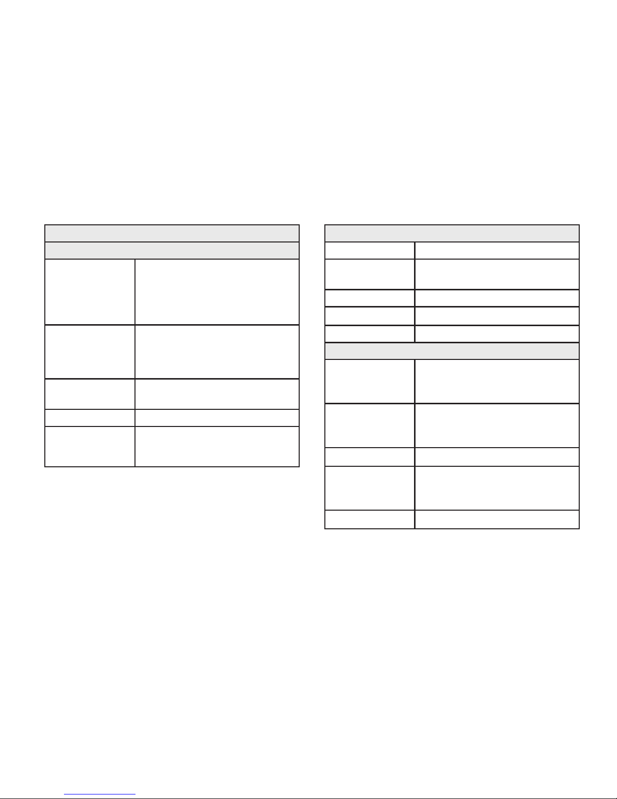
Specications | HOOK X series
HOOK -4x & HOOK-5x
General
Case Size
HOOK 4x: 6.6” H (168 mm) x 3.6” W
(96 mm); 7.5” H (189 mm) with bracket
HOOK-5x: 5.4” H (136 mm) x 6.9”
W (174 mm); 5.9” H (151 mm) with
bracket
Display
HOOK-4x: (4.3” diagonal) 16-bit color
TFT LCD
HOOK-5x: (5” diagonal) 16-bit color
Full color VGA Solar MAX™ Plus TFT
Waterproof
standard
IPX7
Backlight LED (11 levels)
Communications
HOOK-5x: NMEA 0183 Output
(Requires optional Power/NMEA cable
000-0127-49)
Power
Transmit Power 500 W RMS
Power
Requirement
12 V
Voltage Input 10 to 17 V
Current drain
Typical: 1.1 A
Fuse type 3-amp Automotive
Sonar
Max depth
300 ft (91 m) 455/800 kHz
1000 ft (305 m) 83/200 kHz
2500 ft (762 m) 50/200 kHz
Available transducer frequencies
455/800 kHz
50/83/200 kHz
High/Medium/Low CHIRP
Max speed
70 mph
Transducer
HDI 50/200 kHz (Low/High CHIRP)
HDI 83/200 kHz (Medium/High CHIRP)
83/200 kHz (Medium/High CHIRP)
Transducer cable 20 ft (6 m)
Page 34
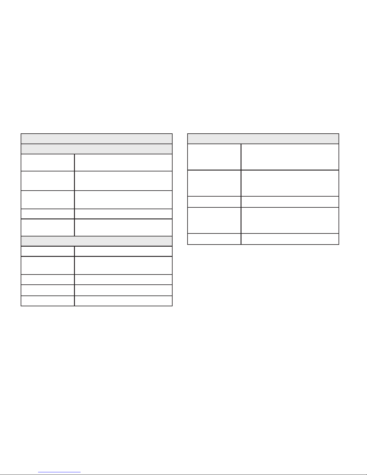
34
Specications | HOOK X series
HOOK -7x
General
Case Size
5.3” H (234 mm) x 9.2” W (136 mm);
5.9” H (151 mm) with bracket
Display
(7” diagonal) 16-bit color Full VGA
Solar MAX™ color TFT
Waterproof
standard
IPX7
Backlight LED (11 levels)
Communications
NMEA 0183 Output (Requires optional
Power/NMEA cable 000-0127-49)
Power
Transmit Power 500 W RMS
Power
Requirement
12 V
Voltage Input 10 to 17 V
Current drain
Typical: 1.1 A
Fuse type 3-amp Automotive
Sonar
Max depth
300 ft (91 m) 455/800 kHz
1000 ft (305 m) 83/200 kHz
2500 ft (762 m) 50 kHz
Available transducer frequencies
455/800 kHz
50/83/200 kHz
High/Medium/Low CHIRP
Max speed
70 mph
Transducer
HDI 50/200 kHz (Low/High CHIRP)
HDI 83/200 kHz (Medium/High CHIRP)
83/200 kHz (Medium/High CHIRP)
Transducer cable 20 ft (6 m)
Page 35

Contact information
Customer Service:
AMER: 800-628-4487
EMEA: +44 1794 51 0010
APAC: 1300 628426
Ordering accessories
US: http://store.navico.com
Other countries: Visit your local dealer or distributor.
Visit our website
For additional regional support information:
www.lowrance.com/technicalsupport
Page 36

*988-11012-002*
www.lowrance.com
 Loading...