

Page 1
Hook2 X Series
Operator Manual
4x GPS, 4x Sonar, 5x GPS HDI, 7x GPS HDI
ENGLISH
www.lowrance.com
Page 2

Page 3

Preface
Disclaimer
As Navico is continuously improving this product, we retain the
right to make changes to the product at any time which may not be
reflected in this version of the manual. Please contact your nearest
distributor if you require any further assistance.
It is the owner’s sole responsibility to install and use the equipment
in a manner that will not cause accidents, personal injury or
property damage. The user of this product is solely responsible for
observing safe boating practices.
NAVICO HOLDING AS AND ITS SUBSIDIARIES, BRANCHES AND
AFFILIATES DISCLAIM ALL LIABILITY FOR ANY USE OF THIS PRODUCT
IN A WAY THAT MAY CAUSE ACCIDENTS, DAMAGE OR THAT MAY
VIOLATE THE LAW.
Governing Language: This statement, any instruction manuals, user
guides and other information relating to the product
(Documentation) may be translated to, or has been translated from,
another language (Translation). In the event of any conflict between
any Translation of the Documentation, the English language version
of the Documentation will be the official version of the
Documentation.
This manual represents the product as at the time of printing.
Navico Holding AS and its subsidiaries, branches and affiliates
reserve the right to make changes to specifications without notice.
Trademarks
Lowrance® and Navico® are registered trademarks of Navico Holding
AS.
Navico product references
This manual refers to the following Navico product:
• DownScan Imaging™ (DownScan)
Copyright
Copyright © 2017 Navico Holding AS.
Preface | Hook² X Series Operator Manual
3
Page 4

Warranty
The warranty card is supplied as a separate document.
In case of any queries, refer to the brand website of your display or
system: www.lowrance.com.
Compliance statements
This equipment complies with:
• CE under 2014/53/EU Directive
• The requirements of level 2 devices of the Radio communications
(Electromagnetic Compatibility) standard 2008
The relevant Declaration of Conformity is available in the product's
section at the following website: www.lowrance.com.
About this manual
This manual is a reference guide for operating the following Hook2 X
models: 4x GPS, 4x Sonar, 5x GPS HDI, and 7x GPS HDI.
These units are only capable of the sonar views and frequencies
indicated in the specification included in the transducer’s
installation guide for the transducer provided with the unit. The
model is provided on the front of the unit. The following is a list of
the models, the transducer which should be used and the sonar
functionality available.
• 4 X Sonar and 4 X GPS: The Bullet transducer should be used
which provides traditional sonar functionality only.
• 5 X GPS HDI and 5 X GPS HDI: The SplitShot transducer should be
used which provides traditional sonar and DownScan
functionality.
Transducers added via one of the optional transducer adapter
cables will still only have the available views and frequencies that
the display is designed to work with. Airmar transducers are not
supported via the adapter cable.
In the manual, important text that requires special attention from
the reader is emphasized as follows:
Note: Used to draw the reader’s attention to a comment or
Ú
some important information.
4
Preface | Hook² X Series Operator Manual
Page 5

Warning: Used when it is necessary to warn
personnel that they should proceed carefully to
prevent risk of injury and/or damage to equipment/
personnel.
Preface | Hook² X Series Operator Manual
5
Page 6

6
Preface | Hook² X Series Operator Manual
Page 7

Contents
9 Introduction
Front controls
9
10 Application pages
11 Basic operation
11 System Controls dialog
11 Settings
12 Turning the system on and off
12 Display illumination
12 Data Overlay
13 Stop sonar
14 GPS plotter
14 GPS plotter page
15 Vessel symbol
15 GPS plotter page scale
15 Panning the GPS plotter image
15 Positioning the vessel on the page
16 Waypoints, Routes, and Trails
16 Navigating
16 GPS plotter settings
18 Waypoints, Routes, and Trails
18 Waypoints, Routes, and Trails dialogs
19 Waypoints
20 Routes
20 Trails
20 Editing waypoints, routes and trails
22 Navigating
22 Navigate to cursor position
22 Navigate to a waypoint
22 Navigate a route
23 Sonar
23 The Sonar image
24 Zooming the image
Contents | Hook² X Series Operator Manual
7
Page 8

24 Customize the image settings
24
Custom and Ice Fishing mode options
24 Fish ID
24 Sonar settings
26 Flasher
26 The Flasher image
27 Customize the image settings
27 Custom and ice fishing mode options
28 DownScan
28 The DownScan image
28 Zooming the DownScan image
28 Customize the image settings
30 Alarms
30 Alarm system
30 Alarms dialog
31 Maintenance
31 Preventive maintenance
31 Cleaning the display unit
31 Checking the connectors
8
Contents | Hook² X Series Operator Manual
Page 9

2
3
5
4
6
7
1
1
Introduction
Front controls
1 Pages - Press to toggle between available pages.
2 Zoom in/out - Press to zoom the image.
Press both keys simultaneous to create a MOB (Man Over
Board) waypoint at the vessel's position.
Note: Creating a MOB waypoint is not available on 4x
Ú
Sonar only models.
3 Arrows - Press to pan the image in any direction.
On the GPS Plotter page: press to position the cursor on the
image.
Note: The GPS Plotter page is not available on 4x Sonar
Ú
only models.
In menus and dialogs: press to highlight an option.
4 Exit (X) - In menus and dialogs: press to return to previous
menu level and to exit a dialog.
5 Menu/Enter - With no menu or dialog active: press to
display the menu.
In menus and dialogs: press to confirm a selection.
6 Cursor/Waypoint - On the GPS Plotter page: Press to
activate/deactivate the cursor.
On any page: press and hold to save a waypoint.
Note: On 4x Sonar only models this is a Fish ID toggle
Ú
key. Press to toggle between fish arches and fish
symbols on the sonar image.
7 Power - Press to display the System Controls dialog.
Press and hold to power the unit on/off.
Introduction | Hook² X Series Operator Manual
9
Page 10
Application pages
1
3
2
4
5
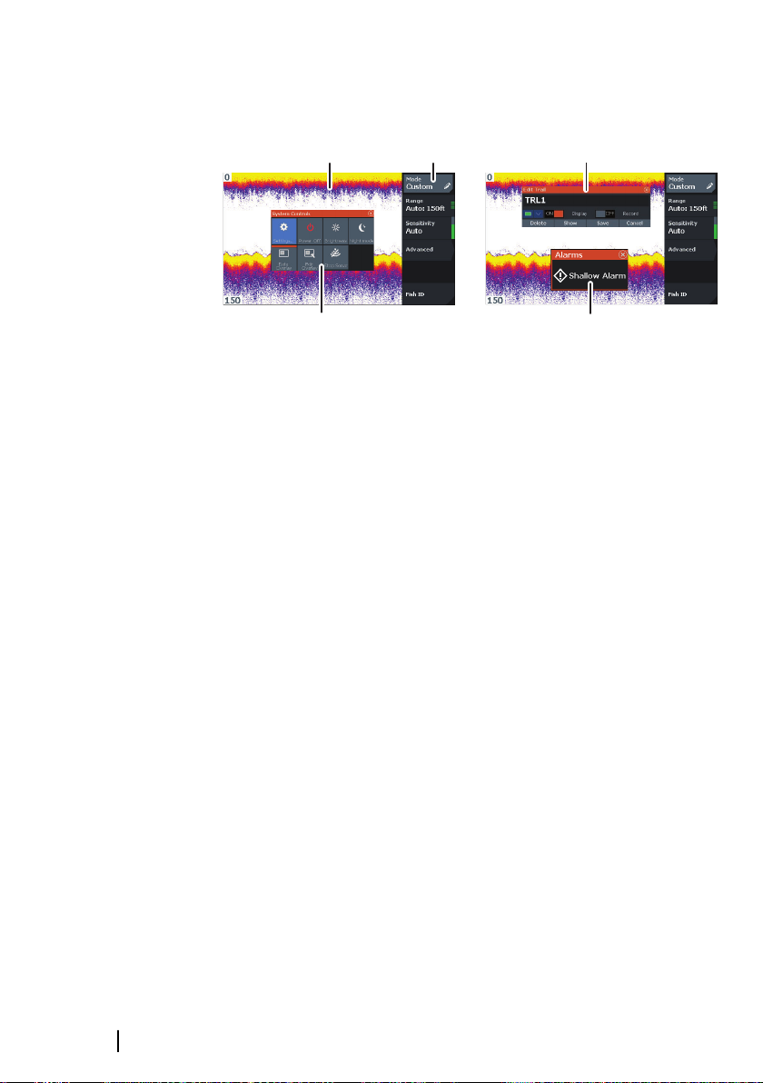
1 Application panel
2 Menu - Panel specific menu.
3 System Controls dialog - Quick access to basic system
settings.
4 Dialog - Information to or input from the user.
5 Alarm message - Displayed if dangerous situations or
system faults occur.
Each application connected to the system is presented on panels.
10
Introduction | Hook² X Series Operator Manual
Page 11
2
Basic operation
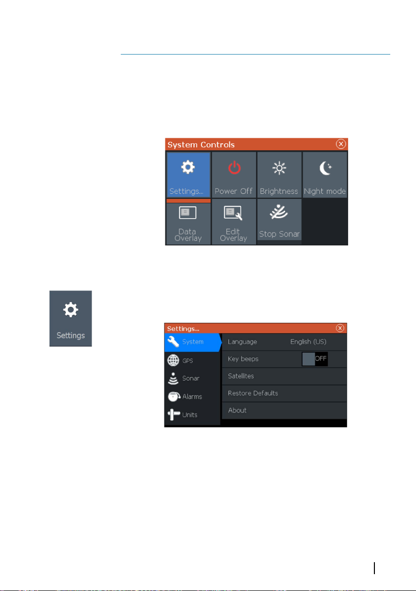
System Controls dialog
The System Controls dialog provides quick access to basic system
settings. You display the dialog by making a short press on the
Power key.
Settings
Provides access to application and system settings.
The system settings dialog available on models with GPS.
The system settings dialog available on the 4x Sonar only models.
Basic operation | Hook² X Series Operator Manual
11
Page 12

Turning the system on and off
You turn the system on and off by pressing and holding the Power
key. You can also turn the unit off from the System Controls dialog.
If the Power key is released before the shut-down is completed, the
power off process is cancelled.
Display illumination
Brightness
The display backlighting can be adjusted at any time from the
System Controls dialog.
You can also cycle the preset backlight levels by short presses on
the Power key.
Night mode
The night mode option optimizes the color palette and backlight for
low light conditions.
Note: Details on the panel may be less visible when the Night
Ú
mode is selected.
Data Overlay
You can have data information as overlay on pages. The data
overlay is global to all pages.
12
Turning Data overlay on and off
You can turn overlay data on or off for all pages by selecting the
Data overlay icon on the System Controls dialog. When Data overlay
is on, an orange bar appears above the icon.
Basic operation | Hook² X Series Operator Manual
Page 13

Edit overlay data
On models with GPS, you can have up to 3 data overlays on the
GPS , sonar and DownScan (available on 5x and 7x models only)
pages. Use the Edit overlay option on the System Controls dialog to:
• Change a selected data overlay to display different data.
• Select a predefined size from the size drop-down list.
• Select the OFF option in the predefined size drop-down list to
remove the selected data overlay from the page.
On 4x Sonar only models, you can have up to 3 data overlays on the
sonar page. Use the Edit overlay option on the System Controls
dialog to:
• Select a predefined size from the size drop-down list.
• Select the OFF option in the predefined size drop-down list to
remove the selected data overlay from the page.
Stop sonar
Select the Stop sonar option in the System Controls dialog to stop
all sonar from pinging. Use the stop sonar option anytime you want
to disable all sonar but not power off the unit.
Basic operation | Hook² X Series Operator Manual
13
Page 14

GPS plotter
1
2
3
6
4
5
Note: The GPS plotter page is not available on 4x Sonar only
Ú
models.
3
The GPS plotter page displays your vessel’s position. On the GPS
plotter page you can plan and navigate routes, see your vessel's
trail, and place waypoints.
GPS plotter page
• Zoom the image by using the Zoom keys
• Pan the image in any direction by using the Arrow keys
• Display item information by positioning the cursor on an item
then selecting the Info option in the menu
14
1 Data overlay (Can be edited, moved or removed. Refer to
"Data Overlay" on page 12).
2 Waypoint*
3 Vessel with trail (displaying the trail is optional*)
4 Route*
5 North indicator
6 Range scale
GPS plotter | Hook² X Series Operator Manual
Page 15

* Optional items. You turn the optional items on/off individually
N
N
from the GPS settings dialog.
Vessel symbol
When the system has a valid GPS position lock, the vessel symbol
indicates vessel position. If no GPS position is available, the vessel
symbol includes a question mark.
GPS plotter page scale
You zoom in and out on the GPS plotter page by using the Zoom
keys.
The GPS plotter page range scale is shown in the lower right corner
of the page.
Panning the GPS plotter image
You can move the image in any direction by using the Arrow keys
to move the cursor to the edge of the panel in the desired direction.
To remove the cursor and cursor elements from the page, press the
Cursor/Waypoint key. This also centers the image to the vessel
position.
Positioning the vessel on the page
GPS image orientation
You can specify how the GPS image is rotated in the panel. The
orientation symbol in the panel’s upper right corner indicates the
north direction.
North up
GPS plotter | Hook² X Series Operator Manual
Course up
15
Page 16

North up
Displays the GPS plotter image with north upward.
Course up
The GPS plotter image direction is depending on if navigating or
not:
• when navigating: the desired course is oriented up
• if not navigating: the direction the vessel is actually traveling
(COG) is oriented up
Look ahead
Moves the vessel icon on the panel to maximize your view ahead of
the vessel.
Waypoints, Routes, and Trails
You can position and manage waypoints, routes and trails on the
page. For more information, refer to "Waypoints, Routes, and Trails" on
page 18.
Navigating
You can use the page for navigating to the cursor, to a waypoint, or
navigate a route. Refer to "Navigating" on page 22.
16
GPS plotter settings
GPS plotter | Hook² X Series Operator Manual
Page 17

Waypoints, Routes, and Trails
• Waypoints - specifies whether waypoints are (ON) or are not
(OFF) displayed on the GPS image.
• Routes - specifies whether routes are (ON) or are not (OFF)
displayed on the GPS image.
• Trails - specifies whether trails are (ON) or are not (OFF) displayed
on the GPS image.
• Waypoints, routes, trails... - opens the waypoints, routes, and trails
dialogs. Use these dialogs to manage waypoints, routes, and
trails. Refer to "Waypoints, Routes, and dialogs" on page 18.
GPS plotter | Hook² X Series Operator Manual
17
Page 18

Waypoints, Routes, and Trails
Note: Waypoints, routes, and trails are not available on 4x Sonar
Ú
only models.
4
Waypoints, routes, and trails are available on the GPS plotter page.
Waypoints, Routes, and Trails dialogs
The Waypoints, Routes, and Trails dialogs give access to advanced
edit functions and settings for these items.
The dialogs are accessed from the W/R/T option on the panel menu.
They can also be accessed from the Waypoints, Routes and Trails
option on the GPS plotter settings dialog, refer to "GPS plotter settings"
on page 16.
18
Select the menu icon on the dialog to access additional options.
Waypoints, Routes, and Trails | Hook² X Series Operator
Manual
Page 19

Waypoint options Routes options Trails options
Waypoints
A waypoint is a user generated mark positioned on the chart or GPS
plotter panel. Each waypoint has an exact position with latitude and
longitude coordinates. A waypoint is used to mark a position you
later may want to return to. Two or more waypoints can also be
combined to create a route.
Saving waypoints
Press and hold the Cursor/Waypoint key to save a new waypoint.
• With cursor inactive, the waypoint is placed at the vessel's
position
• With cursor active, the waypoint is placed at the cursor position
Creating a Man Overboard waypoint
If an emergency situation should occur, you can save a Man
Overboard (MOB) waypoint at the vessel’s current position by
pressing both the Zoom keys simultaneously.
When you activate the MOB function the following actions are
automatically performed:
• A MOB waypoint is created at the vessel’s position
• The display switches to a zoomed panel, centered on the vessel's
position
• The cursor is positioned on the MOB waypoint, and navigation
information to the MOB waypoint is shown in the cursor
information window
Multiple MOB waypoints are saved by repeatedly pressing the zoom
keys. The cursor information window continues to show navigation
information to the initial MOB waypoint until the cursor is moved or
removed from the panel.
Waypoints, Routes, and Trails | Hook² X Series Operator Manual
19
Page 20

Routes
A route consists of a series of routepoints entered in the order that
you want to navigate them.
Creating a new route on the page
1. Select the new route option from the menu
2. Press the Cursor/Waypoint key to activate the cursor on the
panel
3. Use the Arrow keys to position the cursor at the first routepoint
on the panel
4. Press the Menu/Enter key to create the routepoint
5. Repeat steps 3 and 4 to continue positioning new routepoints
on the panel until the route is completed
6. Press the Exit (X) key when completed and save the route.
Trails
Trails are a graphical presentation of the historical path of the vessel,
allowing you to retrace where you have travelled.
From the factory, the system is set to automatically track and draw
the vessel's movement on the panel. The system continues to
record the trail until the length reaches the maximum points, and
then automatically begins overwriting the oldest points.
The automatic tracking function can be turned off from the Edit
Trails dialog.
20
Creating new Trails
You can start a new trail from the Trails dialog. The dialog is
activated by selecting the trails tab in the dialog displayed when
you select the W/R/T option in the menu.
Editing waypoints, routes and trails
Waypoints, routes and trails are managed from their perspective
dialogs. You edit Waypoints, routes and trails similarly. For example,
to edit a trail:
1. Select W/R/T from the menu
2. Select the trails tab in the dialog
3. Select the trail you want to edit.
Waypoints, Routes, and Trails | Hook² X Series Operator
Manual
Page 21

Waypoints, Routes, and Trails | Hook² X Series Operator Manual
21
Page 22

5
Navigating
Note: Navigating is not available on 4x Sonar only models.
Ú
The navigation function is available on the GPS page.
The navigation function included in the system allows you to
navigate to the cursor position, to a waypoint, or along a predefined
route.
For information about positioning waypoints and creating routes,
refer to "Waypoints, Routes, and Trails" on page 18.
When you select to navigate to the cursor position, to a waypoint or
a predefined route, the Navigation option appears in the menu.
Select Navigate to access cancel, restart, and skip a routepoint
options.
Navigate to cursor position
You can start navigating to a cursor position on the GPS plotter or
sonar panel.
Position the cursor at the selected destination on the panel, and
then select the Goto Cursor option in the menu.
Note: The Goto Cursor menu option is not available if you are
Ú
already navigating.
22
Navigate to a waypoint
You can start navigating towards a waypoint on the panel. Position
the cursor over the waypoint, select the waypoint in the menu and
then the Goto waypoint option in the menu.
Navigate a route
You can navigate a route on the image by positioning the cursor
over the route, selecting the route in the menu and then the start
route option in the menu.
When route navigation is started, select the Navigation menu
option for canceling the navigation, skipping a waypoint, and
restarting the route from current vessel position.
Navigating | Hook² X Series Operator Manual
Page 23

3
2
4
1
6
Sonar
The Sonar function provides a view of the water and bottom
beneath your vessel, allowing you to detect fish and examine the
structure of the bottom.
The Sonar image
1 Fish arches
2 Data overlay
3 Range limit
4 Bottom
Sonar | Hook² X Series Operator Manual
23
Page 24

Zooming the image
You can zoom the image by using the Zoom keys.
Customize the image settings
By default the unit is set to Auto mode, and most settings are
automated. It is recommended that only experienced sonar users
use the customize settings to further customize the image.
Select Auto in the menu and change to custom or ice fishing mode
to customize image settings.
Custom and Ice Fishing mode options
Custom and Ice fishing modes allow access to controls for manually
tuning the sonar.
When Custom or Ice Fishing modes are selected the menu expands
with more options. Use these menu options to customize the
image.
Fish ID
You can select how you want the echoes to appear on the screen.
• OFF - As traditional fish arches
• ON - As fish symbols
24
Sonar settings
Sonar | Hook² X Series Operator Manual
Page 25

Depth offset
A
B
All transducers measure water depth from the transducer to the
bottom. As a result, water depth readings do not account for the
distance from the transducer to the lowest point of the boat (for
example; bottom of the keel, rudder, or skeg) in the water or from
the transducer to the water surface.
Before setting the offset, measure the distance from the transducer
to the lowest point of the boat in the water or from the transducer
to the water surface.
A Lowest point of vessel offset: Set the distance from the
transducer to the lowest point of the boat in the water - this
should be set as a negative value. For example, - 0.3 m (-1 ft).
B Depth below surface (waterline) offset: Set the distance from
the transducer to the surface - this should be set as a
positive value. For example, +0.5 m (+1.77 ft).
For depth below transducer, set the offset to 0.
Sonar | Hook² X Series Operator Manual
25
Page 26

34
1 2
5
7
Flasher
The Flasher shows a digital flasher sonar view below your
transducer.
Digital flashers are most commonly used in scenarios such as ice
fishing and vertical jigging where the angler does not care as much
about the sonar history shown on a traditional sonar view, but is
only interested in raw, live sonar returns.
The Flasher image
In the example:
• The colored part of the ring between the depth 0 and 5
represents the sonar returns at or near the surface.
• The white part of the ring between the depth 5 and 26
represents the water column and fish targets within this column.
• The colored part of the ring between the depth 26 and < 0
represents the bottom.
26
1 Flasher sonar ring
2 Range scale
3 Digital depth
Flasher | Hook² X Series Operator Manual
Page 27

4 Water column activity (fish, bait fish, etc.)
5 Depth
Customize the image settings
By default the unit is set to Auto mode, and most settings are
automated. It is recommended that only experienced sonar users
use the customize settings to further customize the sonar image.
Select Auto in the menu and change to custom or ice fishing mode
to customize image settings.
Custom and ice fishing mode options
Custom and ice fishing mode options are similar.
When Custom or ice fishing modes are selected the menu expands
with more options. Use these menu options to customize the
image.
Flasher | Hook² X Series Operator Manual
27
Page 28

2
1
8
DownScan
Note: DownScan is available on 5x and 7x models only.
Ú
DownScan provides detailed images of structure and fish directly
below your boat, down to 91 m (300 ft) at 455 kHz and 46 m (150 ft)
at 800 kHz.
The DownScan image
1 Data overlay
2 Range limit
Zooming the DownScan image
You can zoom a DownScan image by using the Zoom keys.
Customize the image settings
By default the unit is set to Auto mode, and most settings are
automated. It is recommended that only experienced sonar users
use the customize settings to further customize the sonar image.
Select Auto in the menu and change to custom mode to customize
image settings.
28
DownScan | Hook² X Series Operator Manual
Page 29

Custom mode options
When the custom mode is selected the menu expands with more
options. Use these menu options to customize the image.
DownScan | Hook² X Series Operator Manual
29
Page 30

9
Alarms
Alarm system
The system continuously checks for dangerous situations and
system faults while the system is running. When an alarm situation
occurs, an alarm message pops up on the screen.
If you have enabled the siren, the alarm message is followed by an
audible alarm.
Alarms dialog
Enable the alarm siren from the Alarms dialog.
Select the settings option to open the Alarms Settings dialog. All
alarms are setup in the Alarms Settings dialog.
30
Alarms | Hook² X Series Operator Manual
Page 31

Maintenance
Preventive maintenance
10
The unit does not contain any field serviceable components.
Therefore, the operator is required to perform only a very limited
amount of preventative maintenance.
It is recommended that you always fit the protective sun cover
when the unit is not in use.
Ú
Cleaning the display unit
To clean the screen:
• A micro-fiber or a soft cotton cloth should be used to clean the
To clean the housing:
• Use warm water with a dash of liquid dish soap or detergent.
Note: The protective sun cover is an accessory (sold separately).
Refer to the Installation guide provided with your unit.
screen. Use plenty of water to dissolve and take away salt
remains. Crystallized salt, sand, dirt, etc. can scratch the protective
coating if using a damp cloth. Use a light fresh water spray then
wipe the unit dry with a micro-fiber or a soft cotton cloth. Do not
apply pressure with the cloth.
Avoid using abrasive cleaning products or products containing
solvents (acetone, mineral turpentine, etc.), acid, ammonia, or
alcohol as they can damage the display and plastic housing.
Do not use a jet or high pressure wash. Do not run your unit
through a car wash.
Checking the connectors
The connectors should be checked by visual inspection only.
Push the connector plugs into the connector. If the connector plugs
are equipped with a position key, ensure that it is in the correct
position.
Maintenance | Hook² X Series Operator Manual
31
Page 32

32
Maintenance | Hook² X Series Operator Manual
Page 33

Page 34

*988-11747-002*
 Loading...