

Page 1
DIGITAL VIDEO SURVEILLANCE RECORDER
Instruction Manual
English Version 2.0
RETAIL
INDUSTRY
www.lorextechnology.com
Copyright © 2012 Lorex Technology Inc.
BUSINESS HOME
BUSINESS
OUTDOOR
LHD100 SERIES
Page 2
Thank you for purchasing the LHD100 Series High Definition Digital Video Surveillance
Recorder.
This manual refers to the following models:
• LHD104 (4-channel)
• LHD108 (8-channel)
For the latest online manual, downloads and product updates, and to learn about our
complete line of accessory products, please visit our website at:
www.lorextechnology.com
CAUTION
RISK OF ELECTRIC SHOCK
DO NOT OPEN
CAUTION: TO REDUCE THE RICK OF ELECTRIC SHOCK DO NOT
REMOVE COVER. NO USER SERVICABLE PARTS INSIDE.
REFER SERVICING TO QUALIFIED SERVICE PERSONNEL.
The lightning flash with arrowhead symbol, within an equilateral
triangle, is intended to alert the user to the presence of uninsulated
"dangerous voltage" within the products ' enclosure that may be of
sufficient magnitude to constitute a risk of electric shock.
The exclamation point within an equilateral triangle is intended to
alert the user to the presence of important operating and
maintenance (servicing) instructions in the literature accompanying
the appliance.
WARNING: TO PREVENT FIRE OR SHOCK HAZARD, DO NOT
EXPOSE THIS UNIT TO RAIN OR MOISTURE.
CAUTION: TO PREVENT ELECTRIC SHOCK, MATCH WIDE BLADE
OF THE PLUG TO THE WIDE SLOT AND FULLY INSERT.
Page 3

NEED HELP?
CONTACT US FIRST
DO NOT RETURN THIS PRODUCT TO THE STORE
Please make sure to register your product at www.lorextechnology.com
to receive product updates and technical support.
2 Easy Ways to Contact Us
Online:
Product Support is available 24/7 including product information, user
manuals, quick start up guides and FAQ’s at
www.lorextechnology.com/support
For all other matters, visit www.lorextechnology.com
By Phone:
North America:
Customer Service (for warranty matters): 1-888-425-6739 (1-888-42-LOREX)
Tech Support (for technical/installation issues): 1-877-755-6739 (1-877-75-LOREX)
Mexico: 001-800-681-9263, 001-800-514-6739
International: +800-425-6739-0
SEP 12 2012 - R14
(Example: From the UK, dial 00 instead of +)
Page 4

VIEW YOUR WORLD™
VOIR VOTRE MONDE
VEA SU MUNDO™
MD
¿NECESITA AYUDA?
COMUNÍQUESE PRIMERO
CON NOSOTROS
NO DEVUELVA ESTE PRODUCTO A LA TIENDA NE RETOURNEZ PAS CE PRODUIT AU MAGASIN
Por favor, registre su producto en www.lorextechnology.
com para recibir actualizaciones del producto y
asistencia técnica.
Hay 2 maneras fáciles de comunicarse
con nosotros:
En línea:
Apoyo al cliente está disponible 24/7, incluyendo
información del producto, manuales para el usuario, guías
de inicio rápido y preguntas más frecuentes en:
www.lorextechnology.com/support
BESOIN D’ASSISTANCE?
COMMUNIQUEZ D’ABORD
AVEC NOUS
Veuillez enregistrer votre produit sur le site
www.lorextechnology.com afin de recevoir des mises à jour
et le soutien technique pour votre produit.
2 façons simples de communiquer
avec nous :
En ligne :
À votre disposition 24/7, le soutien pour les produits comprend
les renseignements sur les produits, guides d’utilisation, guides
de départ rapide et FAQ :
www.lorextechnology.com/support
Para todo lo demás, visite
www.lorextechnology.com
Por teléfono:
Norte América:
Atención al cliente (para asuntos de la garantía):
1-888-425-6739 (1-888-42-LOREX)
Asistencia técnica (para asuntos técnicos o de instalación):
1-877-755-6739 (1-877-75-LOREX)
Mexico: 001-800-681-9263, 001-800-514-6739
Internacional: +800-425-6739-0
(Ejemplo: Desde el Reino Unido, marque el 00 en lugar del +)
Pour toutes les autres questions,
visitez www.lorextechnology.com
Par téléphone :
En Amérique du Nord :
Service à la clientèle (pour tout ce qui concerne la garantie) :
1-888-425-6739 (1-888-42-LOREX)
Soutien technique (pour les questions d’ordre technique ou relatives à
l’installation) : 1-877-755-6739 (1-877-75-LOREX)
Mexique : 001-800-681-9263, 001-800-514-6739
International : +800-425-6739-0
(par exemple : à partir du Royaume-Uni, composez le 00 au lieu de +)
SEP 12 2012 - R14
Page 5
BEFORE YOU START
Please make sure to register your product at www.lorextechnology.com
to receive product updates and technical support
THIS PRODUCT MAY REQUIRE PROFESSIONAL INSTALLATION
LOREX IS COMMITTED TO FULFILLING YOUR SECURITY NEEDS
• We have developed user friendly products and documentation.
Please read the Quick Start Guide and User Manual before you
install this product.
• Consumer Guides and Video Tutorials are available on our web
site at www.lorextechnology.com/support
• If you require further installation assistance, please visit
www.lorextechnology.com/installation or contact a
professional installer.
• Please note that once the components of this product have been
unsealed, you cannot return this product directly to the store
without the original packaging.
SEP 6 2012 - R8
Page 6

AVANT DE
ANTES DE
COMMENCER
Veuillez enregistrer votre produit sur le site
www.lorextechnology.com afin de recevoir
des mises à jour et le soutien technique pour
votre produit.
CE PRODUIT PEUT NÉCESSITER UNE
INSTALLATION PROFESSIONNELLE
LOREX S’ENGAGE À RÉPONDRE À VOS
BESOINS EN MATIÈRE DE SÉCURITÉ
• Nous avons conçu et développé une documentation
et des produits extrêmement conviviaux. Veuillez
lire le Guide de départ rapide et le Guide
d’utilisation avant d’installer ce produit.
• Des guides pour consommateurs et des tutoriels
EMPEZAR
Cerciórese de por favor colocar su producto
en www.lorextechnology.com para recibir
actualizaciones y la información del producto
y soporte técnico.
ESTE PRODUCTO PUEDE EXIGIR UNA INSTALACIÓN PROFESIONAL
LOREX SE COMPROMETE A SATISFACER
SUS NECESIDADES EN SEGURIDAD
• Favor de leer la guía de instalación rápida y la
guía del usuario antes de instalar este product.
• Puede conseguir las guías del consumidor y los
cursos en enseñanza video sobre el Internet
visitando www.lorextechnology.com/support
vidéo vous sont offerts sur notre site Web :
www.lorextechnology.com/support
• Si vous avez besoin de plus d’assistance pour
l’installation de ce produit, veuillez visiter le site
www.lorextechnology/installation ou communiquez
avec un installateur professionnel.
• Veuillez prendre note que lorsque vous avez déballé
les pièces et composantes de ce produit, vous ne
pouvez pas retourner celui-ci directement au
magasin sans son emballage original.
www.lorextechnology.com
• Si necesita ayuda para la instalación, visite
www.lorextechnology.com/installation o contacte
un especialista en instalaciones.
• Favor de notar que una vez que los componentes
de este producto han sido removidos del
embalaje, no podrá devolver este producto
directamente a la tienda.
VIEW YOUR WORLD™
VOIR VOTRE MONDE
VEA SU MUNDO™
MD
SEP 6 2012 - R8
Page 7

Important Safeguards
In addition to the careful attention devoted to quality standards in the manufacture process of your
product, safety is a major factor in the design of every instrument. However, safety is your
responsibility too. This sheet lists important information that will help to ensure your enjoyment
and proper use of the product and accessory equipment. Please read them carefully before
operating and using your product.
General Precautions
1. All warnings and instructions in this manual should be followed.
2. Remove the plug from the outlet before cleaning. Do not use liquid aerosol detergents. Use a
water-dampened cloth for cleaning.
3. Do not use this product in humid or wet places.
4. Keep enough space around the product for ventilation. Slots and openings in the storage
cabinet should not be blocked.
5. It is highly recommended to connect the product to a surge protector to protect from damage
caused by electrical surges. It is also recommended to connect the product to an
uninterruptible power supply (UPS), which has an internal battery that will keep the product
running in the event of a power outage.
6.
Installation
1. Read and Follow Instructions - All the safety and
operating instructions should be read before the product
is operated. Follow all operating instructions.
2. Retain Instructions - The safety and operating
instructions should be retained for future reference.
3. Heed Warnings - Comply with all warnings on the
product and in the operating instructions.
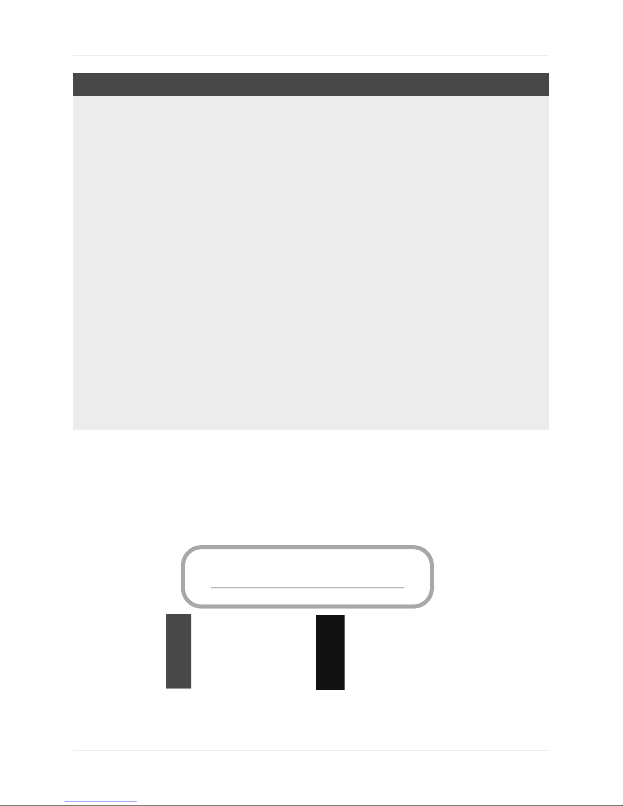
4. Polarization - Do not defeat the safety
purpose of the polarized or
grounding-type plug.
A polarized plug has two blades with
one wider than the other.
A grounding type plug has two blades
and a third grounding prong.
The wide blade or the third prong are
rovided for your safety.
p
If the provided plug does not fit into your outlet, consult
an electrician for replacement of the obsolete outlet.
5. Power Sources - This product should be operated only
from the type of power source indicated on the marking
label. If you are not sure of the type of power supplied
to your location, consult your video dealer or local power
company. For products intended to operate from battery
power, or other sources, refer to the operating
instructions.
Overloading - Do not overload wall outlets or
extension cords as this can result in the risk of fire or
electric shock. Overloaded AC outlets, extension
cords, frayed power cords, damaged or cracked wire
insulation, and broken plugs are dangerous. They may
result in a shock or fire hazard. Periodically examine
the cord, and if its appearance indicates damage or
deteriorated insulation, have it replaced by your
service technician.
7. Power-Cord Protection - Power supply cords should
be routed so that they are not likely to be walked on or
pinched by items placed upon or against them. Pay
particular attention to cords at plugs, convenience
receptacles, and the point where they exit from the
product.
Surge Protectors - It is highly recommended that the
8.
product be connected to a surge protector. Doing so
will protect the product from damage caused by power
surges. Surge protectors should bear the UL listing
mark or CSA certification mark.
9. Uninterruptible Power Supplies (UPS) - Because
this product is designed for continuous,
24/7 operation, it is recommended that you connect
the product to an uninterruptible power supply. An
uninterruptible power supply has an internal battery
that will keep the product running in the event of a
power outage. Uninterruptible power supplies should
bear the UL listing mark or CSA certification mark.
Caution: Maintain electrical safety. Power line
operated equipment or accessories connected to this
product should bear the UL listing mark or CSA
certification mark on the accessory itself and should
not be modi fied so as to defeat the safety features. This
will help avoid any potential hazard from electrical
shock or fire. If in doubt, contact qualified service
personnel.
v
Page 8

Installation (Continued)
10. Ventilation - Slots and openings in the case are
provided for ventilation to ensure reliable operation of
the product and to protect it from overheating. These
openings must not be blocked or covered. The
openings should never be blocked by placing the
product on a bed, sofa, rug, or other similar surface.
This product should never be placed near or over a
radiator or heat register. This product should not be
placed in a built-in installation such as a bookcase or
rack unless proper ventilation is provided and the
product manufacturer’s instructions have been
followed.
11. Attachments - Do not use attachments unless
recommended by the product manufacturer as they
may cause a hazard.
12. Water and Moisture - Do not use this product near
water — for example, near a bath tub, wash bowl,
kitchen sink or laundry tub, in a wet basement, near a
swimming pool and the like.
13. Heat - The product should be situated away from heat
sources such as radiators, heat registers, stoves, or
other products (including amplifiers) that produce
heat.
14. Accessories - Do not place this
product on an unstable cart,
stand, tripod, or table. The product
may fall, causing serious damage
to the product. Use this product
only with a cart, stand, tripod,
bracket, or table recommended by
the manufacturer or sold with the
product. Any mounting of the
product should follow the manufacturer’s instructions
and use a mounting accessory recommended by the
manufacturer.
15. Camera Extension Cables – Check the rating of
your extension cable(s) to verify compliance with your
local authority regulations prior to installation.
Mounting - The cameras provided with this system
16.
should be mounted only as instructed in this guide or
the instructions that came with your cameras, using
the provided mounting brackets.
17. Camera Installation- Cameras are not intended for
submersion in water. Not all cameras can be installed
outdoors. Check your camera environmental rating to
confirm if they can be installed outdoors. When
installing cameras outdoors, installation in a sheltered
area is required.
Service
1. Servicing - Do not attempt to service this product
yourself, as opening or removing covers may expose
you to dangerous voltage or other hazards. Refer all
servicing to qualified service personnel.
2. Conditions Requiring Service - Unplug this product
from the wall outlet and refer servicing to qualified
service personnel under the following conditions:
A. When the power supply cord or plug is damaged.
B. If liquid has been spilled or objects have fallen into
the pr
oduct.
C. If the product has been exposed to rain or water.
D. If the product has been dropped or the cabinet has
been damaged.
E. If the product does not operate normally by
fo
llowing the operating instructions. Adjust only those
controls that are covered by the operating
instructions. Improper adjustment of other controls
may result in damage and will often require extensive
work by a qualified technician to restore the product
to its normal operation.
F. When the product exhibits a distinct change in
performance. This indicates a need for service.
7. Replacement Parts - When replacement parts are
required, have the service technician verify that the
replacements used have the same safety
characteristics as the original parts. Use of
replacements specified by the product manufacturer
can prevent fire, electric shock, or other hazards.
8. Safety Check - Upon completion of any service or
repairs to this product, ask the service technician to
perform safety checks recommended by the
manufacturer to determine that the product is in safe
operating condition.
Use
1. Cleaning - Unplug the product from the wall outlet
before cleaning. Do not use liquid cleaners or aerosol
cleaners. Use a damp cloth for cleaning.
2. Product and Cart Combination - When product is
installed on a cart, product and cart combination
should be moved with care. Quick stops, excessive
force, and uneven surfaces may cause the product and
cart combination to overturn.
3. Object and Liquid Entry - Never push objects of any
kind into this product through openings as they may
touch dangerous voltage points or “short-out” parts
that could result in a fire or electric shock. Never spill
liquid of any kind on the product.
vi
4. Lightning - For added protection of this product
during a lightning storm, or when it is left unattended
and unused for long periods of time, unplug it from
the wall outlet and disconnect the antenna or cable
system. This will prevent damage to the product due
to lightning and power line surges.
Page 9
NOTICES
FCC/IC Notice:
This equipment has been tested and found to comply with the limits for a Class B digital device, pursuant
to Part 15 of the FCC Rules. These limits are designed to provide reasonable protection against harmful
interference in a residential installation. This equipment generates, uses, and can radiate radio frequency
energy and, if not installed and used in accordance with the instruction, may cause harmful interference
to radio communications.
However, there is no guarantee that interference will not occur in a particular installation. If this
equipment does cause harmful interference to radio or television reception (which can be determined by
turning the equipment on and off), the user is encouraged to try to correct the interference by one or more
of the following measures:
• Reorient or relocate the receiving antenna
• Increase the separation between the equipment and receiver
• Connect the equipment into an outlet on a circuit different from that to which the receiver is connected
• Consult the dealer or an experienced radio or television technician for assistance
Modification:
Any changes or modifications not expressly approved by the grantee of this device could void the user's
authority to operate the device.
Toute modification non approuvée explicitement par le fournisseur de licence de l'appareil peut entraîner
l'annulation du droit de l'utilsateur à utiliser l'appareil.
RoHS:
This product is fully compliant with the European Union Restriction of the Use of Certain Hazardous
Substances in Electrical and Electronic Equipment ("RoHS") Directive (2002/95/EC). The RoHS directive
prohibits the sale of electronic equipment containing certain hazardous substances such as lead,
cadmium, mercury, and hexavalent chromium, PBB, and PBDE in the European Union.
This product has been certified and found to comply with the limits regulated by FCC, EMC, and
www.lorextechnology.com
Product Information
User Manuals
Quick Start Guides
Specification Sheets
Software Upgrades
Firmware Upgrades
LVD. Therefore, it is designated to provide reasonable protection against inter
cause interference with other appliance usage.
ference and will not
However, it is imperative that the user follows the guidelines in this
usage, which may result in damage to the product, electrical shock and fire hazard injury.
In order to improve the features, functions, and quality of
this pr
subject to change without notice from time to time.
manual to avoid improper
oduct, the specifications are
vii
Page 10

Features
Digital Video Recorder Features
• HD-SDI supporting 1080p & 720p recording
• Digital Zoom in live view & playback
• Advanced search & playback: Panorama and Multi-time
• Smart Search for fast review of motion events in sequence
• Pentaplex operation - View, Record, Playback, Backup & Remotely control the system
simultaneousl
y
1
• 24x7
100% duty cycle hard drive pre-installed. Supports 2 hard drives (expandable up to 4TB)
• Variable frame rate for higher recording speed during events
• HDMI Outputs for convenient connection to HDTVs or monitors
• eSATA output for faster large capacity backup
Connectivity Features
• Remote Viewing on PC, Mac, smartphone & tablet
• Exclusive LOREX Easy Connect Internet Set-up Wizard
• Dual streaming to conserve bandwidth
4
2
3
• Free LOREX DDNS (Dynamic Domain Name Service) for reliable connectivity
• Instant e-mail alerts with snap shot attachments and web link
1. High-Definition Serial Digital Interface (HD-SDI) un-compressed high definition broadcast-grade video over
standard coax cable. Total recording speed is 20fps @ 1080p on 4ch or 60fps @ 1080p on 8ch. Per channel
recording speed (with all cameras connected) is 5fps @ 1080p on 4ch or 7.5fps @ 1080p on 8ch. Recording time
may vary based on recording resolution, quality, lighting conditions and movement in the scene.
2. Smartphone & Tablet Compatibility: iPad™, iPhone™, Android (version 2.3 & above). Data plan is required (not
included). Router port forwarding required. For the latest smart phone compatibility list check
www.lorextechnology.com as new smartphones and tablets become available in the market.
3. Requires a high speed internet connection and a router (not included).
4. HD video streaming locally to the DVR. Optimized lower r
tivity is dependent on bandwidth and resolution of the mobile device.
All trademarks belong to their respective owners. No claim is made
listed, other than the trademarks owned by Lorex Technology Inc. We reserve the right to change models, configurations or specifications without notice or liability. Product may not be exactly as shown.
esolution steaming for mobile devices. Mobile connec-
to the exclusive right to use the trademarks
viii
Page 11

TABLE OF CONTENTS
Getting Started . . . . . . . . . . . . . . . . . . . . . . . . . . . . . . . . . . . . . . . . . . . . . . . . . 1
Front Panel . . . . . . . . . . . . . . . . . . . . . . . . . . . . . . . . . . . . . . . . . . . . . . . . . . . . 2
Rear Panel . . . . . . . . . . . . . . . . . . . . . . . . . . . . . . . . . . . . . . . . . . . . . . . . . . . . . 4
4-Channel . . . . . . . . . . . . . . . . . . . . . . . . . . . . . . . . . . . . . . . . . . . . . . . . . . . . . . . . . . . . . . 4
8-Channel . . . . . . . . . . . . . . . . . . . . . . . . . . . . . . . . . . . . . . . . . . . . . . . . . . . . . . . . . . . . . . 5
Basic Setup . . . . . . . . . . . . . . . . . . . . . . . . . . . . . . . . . . . . . . . . . . . . . . . . . . . . 6
Step 1: Connect the Cameras . . . . . . . . . . . . . . . . . . . . . . . . . . . . . . . . . . . . . . . . . . . . . . 6
Step 2: Connect the Mouse . . . . . . . . . . . . . . . . . . . . . . . . . . . . . . . . . . . . . . . . . . . . . . . . 6
Step 3: Connect the Ethernet Cable . . . . . . . . . . . . . . . . . . . . . . . . . . . . . . . . . . . . . . . . . 7
Step 4: Connect the Monitor . . . . . . . . . . . . . . . . . . . . . . . . . . . . . . . . . . . . . . . . . . . . . . . 7
Step 5: Connect the Power Adapter and Power on the DVR . . . . . . . . . . . . . . . . . . . . . 8
Step 6: Verify Camera Image . . . . . . . . . . . . . . . . . . . . . . . . . . . . . . . . . . . . . . . . . . . . . . 8
Step 7: Set the Time . . . . . . . . . . . . . . . . . . . . . . . . . . . . . . . . . . . . . . . . . . . . . . . . . . . . . . 8
Default System Password & Port Numbers . . . . . . . . . . . . . . . . . . . . . . . . . . . . . . . . . . 9
Quick Access to System Information . . . . . . . . . . . . . . . . . . . . . . . . . . . . . . . . . . . . . . . . 9
Connecting Cameras . . . . . . . . . . . . . . . . . . . . . . . . . . . . . . . . . . . . . . . . . . . 10
About HD-SDI . . . . . . . . . . . . . . . . . . . . . . . . . . . . . . . . . . . . . . . . . . . . . . . . . . . . . . . . . . . . . . . . . . . . . . . 10
Installation Warnings . . . . . . . . . . . . . . . . . . . . . . . . . . . . . . . . . . . . . . . . . . . . . . . . . . . . . . . . . . . . . . . . . 10
Installation Tips . . . . . . . . . . . . . . . . . . . . . . . . . . . . . . . . . . . . . . . . . . . . . . . . . . . . . . . . . . . . . . . . . . . . . . 10
Installing Cameras . . . . . . . . . . . . . . . . . . . . . . . . . . . . . . . . . . . . . . . . . . . . . . . . . . . . . . . . . . . . . . . . . . . 10
Connecting HD-SDI Cameras to your DVR . . . . . . . . . . . . . . . . . . . . . . . . . . . . . . . . . . . . . . . . . . . . . . . . 11
Camera Connection Diagram . . . . . . . . . . . . . . . . . . . . . . . . . . . . . . . . . . . . . . . . . . . . . . . . . . . . . . . . . . . 11
Connecting and Removing BNC Cables . . . . . . . . . . . . . . . . . . . . . . . . . . . . . . . . . . . . . . . . . . . . . . . . . . 11
Mouse Control. . . . . . . . . . . . . . . . . . . . . . . . . . . . . . . . . . . . . . . . . . . . . . . . . 12
Remote Control. . . . . . . . . . . . . . . . . . . . . . . . . . . . . . . . . . . . . . . . . . . . . . . . 13
4-Channel Remote Control . . . . . . . . . . . . . . . . . . . . . . . . . . . . . . . . . . . . . . . . . . . . . . . 13
8-Channel Remote Control . . . . . . . . . . . . . . . . . . . . . . . . . . . . . . . . . . . . . . . . . . . . . . . 14
Changing the Remote Control ID (8-Channel Only) . . . . . . . . . . . . . . . . . . . . . . . . . . . . . . . . . . . . . . . . . 15
Using the On-Screen Display. . . . . . . . . . . . . . . . . . . . . . . . . . . . . . . . . . . . . 16
Using the Virtual Keyboard . . . . . . . . . . . . . . . . . . . . . . . . . . . . . . . . . . . . . . . . . . . . . . . 17
Using Zoom Mode . . . . . . . . . . . . . . . . . . . . . . . . . . . . . . . . . . . . . . . . . . . . . . . . . . . . . . . 18
Setting the Date and Time . . . . . . . . . . . . . . . . . . . . . . . . . . . . . . . . . . . . . . . 19
Configuring Daylight Savings Time (DST) . . . . . . . . . . . . . . . . . . . . . . . . . . . . . . . . . . . 20
Using a NTP Server to set your System Time . . . . . . . . . . . . . . . . . . . . . . . . . . . . . . . . 21
Recording and Events . . . . . . . . . . . . . . . . . . . . . . . . . . . . . . . . . . . . . . . . . . 22
ix
Page 12

Playback. . . . . . . . . . . . . . . . . . . . . . . . . . . . . . . . . . . . . . . . . . . . . . . . . . . . . . 23
Playback Toolbar . . . . . . . . . . . . . . . . . . . . . . . . . . . . . . . . . . . . . . . . . . . . . . . . . . . . . . . 23
Playback Sub-Menu . . . . . . . . . . . . . . . . . . . . . . . . . . . . . . . . . . . . . . . . . . . . . . . . . . . . . 24
Smart Search . . . . . . . . . . . . . . . . . . . . . . . . . . . . . . . . . . . . . . . . . . . . . . . . . . . . . . . . . . . . . . . . . . . . . . . 24
Panorama Playback . . . . . . . . . . . . . . . . . . . . . . . . . . . . . . . . . . . . . . . . . . . . . . . . . . . . . . . . . . . . . . . . . . 25
Multi-Time Playback . . . . . . . . . . . . . . . . . . . . . . . . . . . . . . . . . . . . . . . . . . . . . . . . . . . . . . . . . . . . . . . . . . 26
Multi-Day Playback . . . . . . . . . . . . . . . . . . . . . . . . . . . . . . . . . . . . . . . . . . . . . . . . . . . . . . . . . . . . . . . . . . . 27
Event Playback . . . . . . . . . . . . . . . . . . . . . . . . . . . . . . . . . . . . . . . . . . . . . . . . . . . . . . . . . . . . . . . . . . . . . . 28
Using the Main Menu . . . . . . . . . . . . . . . . . . . . . . . . . . . . . . . . . . . . . . . . . . . 29
Setup . . . . . . . . . . . . . . . . . . . . . . . . . . . . . . . . . . . . . . . . . . . . . . . . . . . . . . . . 30
Time . . . . . . . . . . . . . . . . . . . . . . . . . . . . . . . . . . . . . . . . . . . . . . . . . . . . . . . . . . . . . . . . . . 30
Changing the Date Format . . . . . . . . . . . . . . . . . . . . . . . . . . . . . . . . . . . . . . . . . . . . . . . . . . . . . . . . . . . . . 30
Enabling Auto Reboot . . . . . . . . . . . . . . . . . . . . . . . . . . . . . . . . . . . . . . . . . . . . . . . . . . . . . . . . . . . . . . . . . 30
Camera . . . . . . . . . . . . . . . . . . . . . . . . . . . . . . . . . . . . . . . . . . . . . . . . . . . . . . . . . . . . . . . 31
Disconnecting/Connecting Cameras . . . . . . . . . . . . . . . . . . . . . . . . . . . . . . . . . . . . . . . . . . . . . . . . . . . . . 31
Creating Custom Camera Titles . . . . . . . . . . . . . . . . . . . . . . . . . . . . . . . . . . . . . . . . . . . . . . . . . . . . . . . . 32
Enabling Covert Recording . . . . . . . . . . . . . . . . . . . . . . . . . . . . . . . . . . . . . . . . . . . . . . . . . . . . . . . . . . . . 32
Setting Motion Detection Sensitivity . . . . . . . . . . . . . . . . . . . . . . . . . . . . . . . . . . . . . . . . . . . . . . . . . . . . . 33
Setting Sensitivity for Audio Events (4-Channel Only) . . . . . . . . . . . . . . . . . . . . . . . . . . . . . . . . . . . . . . . 33
Configuring Motion Detection Areas . . . . . . . . . . . . . . . . . . . . . . . . . . . . . . . . . . . . . . . . . . . . . . . . . . . . . 34
Recording . . . . . . . . . . . . . . . . . . . . . . . . . . . . . . . . . . . . . . . . . . . . . . . . . . . . . . . . . . . . . 35
Enabling Motion Detection/Motion Events . . . . . . . . . . . . . . . . . . . . . . . . . . . . . . . . . . . . . . . . . . . . . . . . 36
Configuring the DVR for Motion Recording Only . . . . . . . . . . . . . . . . . . . . . . . . . . . . . . . . . . . . . . . . . . . 36
Enabling Sensor Events . . . . . . . . . . . . . . . . . . . . . . . . . . . . . . . . . . . . . . . . . . . . . . . . . . . . . . . . . . . . . . . 38
Enabling Audio Events (4-Channel Only) . . . . . . . . . . . . . . . . . . . . . . . . . . . . . . . . . . . . . . . . . . . . . . . . . 38
Changing the Recording Resolution and Quality . . . . . . . . . . . . . . . . . . . . . . . . . . . . . . . . . . . . . . . . . . . 39
Changing the Recording Frame Rate . . . . . . . . . . . . . . . . . . . . . . . . . . . . . . . . . . . . . . . . . . . . . . . . . . . . 39
Enabling the Event Buzzer . . . . . . . . . . . . . . . . . . . . . . . . . . . . . . . . . . . . . . . . . . . . . . . . . . . . . . . . . . . . . 40
Enabling Full-screen Popup on Events . . . . . . . . . . . . . . . . . . . . . . . . . . . . . . . . . . . . . . . . . . . . . . . . . . . 41
Configuring Alarm Durations . . . . . . . . . . . . . . . . . . . . . . . . . . . . . . . . . . . . . . . . . . . . . . . . . . . . . . . . . . . 41
Enabling/Disabling Event Logs . . . . . . . . . . . . . . . . . . . . . . . . . . . . . . . . . . . . . . . . . . . . . . . . . . . . . . . . . 42
Schedule . . . . . . . . . . . . . . . . . . . . . . . . . . . . . . . . . . . . . . . . . . . . . . . . . . . . . . . . . . . . . . 43
Setting the Schedule . . . . . . . . . . . . . . . . . . . . . . . . . . . . . . . . . . . . . . . . . . . . . . . . . . . . . . . . . . . . . . . . . . 43
Selecting Holidays . . . . . . . . . . . . . . . . . . . . . . . . . . . . . . . . . . . . . . . . . . . . . . . . . . . . . . . . . . . . . . . . . . . . 45
Storage . . . . . . . . . . . . . . . . . . . . . . . . . . . . . . . . . . . . . . . . . . . . . . . . . . . . . . . . . . . . . . . 45
Disabling/Enabling Overwrite . . . . . . . . . . . . . . . . . . . . . . . . . . . . . . . . . . . . . . . . . . . . . . . . . . . . . . . . . . 45
Formatting a Hard Drive . . . . . . . . . . . . . . . . . . . . . . . . . . . . . . . . . . . . . . . . . . . . . . . . . . . . . . . . . . . . . . . 46
Formatting a USB Thumb Drive . . . . . . . . . . . . . . . . . . . . . . . . . . . . . . . . . . . . . . . . . . . . . . . . . . . . . . . . . 48
Enabling Private Recording . . . . . . . . . . . . . . . . . . . . . . . . . . . . . . . . . . . . . . . . . . . . . . . . . . . . . . . . . . . . 48
Network . . . . . . . . . . . . . . . . . . . . . . . . . . . . . . . . . . . . . . . . . . . . . . . . . . . . . . . . . . . . . . . 49
Configuring Network Type: DHCP or Static IP . . . . . . . . . . . . . . . . . . . . . . . . . . . . . . . . . . . . . . . . . . . . . 49
Enabling DDNS . . . . . . . . . . . . . . . . . . . . . . . . . . . . . . . . . . . . . . . . . . . . . . . . . . . . . . . . . . . . . . . . . . . . . . 50
Changing the Web and Client Ports . . . . . . . . . . . . . . . . . . . . . . . . . . . . . . . . . . . . . . . . . . . . . . . . . . . . . . 51
Enabling Auto Port Forwarding . . . . . . . . . . . . . . . . . . . . . . . . . . . . . . . . . . . . . . . . . . . . . . . . . . . . . . . . . 51
Enabling Email Notifications . . . . . . . . . . . . . . . . . . . . . . . . . . . . . . . . . . . . . . . . . . . . . . . . . . . . . . . . . . . 52
Configuring Bandwidth (Dual Streaming) Settings . . . . . . . . . . . . . . . . . . . . . . . . . . . . . . . . . . . . . . . . . 54
x
Page 13

System . . . . . . . . . . . . . . . . . . . . . . . . . . . . . . . . . . . . . . . . . . . . . . . . . . . . . . . . . . . . . . . . 55
Upgrading Firmware . . . . . . . . . . . . . . . . . . . . . . . . . . . . . . . . . . . . . . . . . . . . . . . . . . . . . . . . . . . . . . . . . . 55
Resetting to Factory Default Settings . . . . . . . . . . . . . . . . . . . . . . . . . . . . . . . . . . . . . . . . . . . . . . . . . . . . 56
Changing the System Language . . . . . . . . . . . . . . . . . . . . . . . . . . . . . . . . . . . . . . . . . . . . . . . . . . . . . . . . 57
Configuring the Menu Time Out Duration . . . . . . . . . . . . . . . . . . . . . . . . . . . . . . . . . . . . . . . . . . . . . . . . . 57
Changing the DVR Name . . . . . . . . . . . . . . . . . . . . . . . . . . . . . . . . . . . . . . . . . . . . . . . . . . . . . . . . . . . . . . 58
Configuring Error Notifications . . . . . . . . . . . . . . . . . . . . . . . . . . . . . . . . . . . . . . . . . . . . . . . . . . . . . . . . . 58
Search . . . . . . . . . . . . . . . . . . . . . . . . . . . . . . . . . . . . . . . . . . . . . . . . . . . . . . . 60
Calendar Search . . . . . . . . . . . . . . . . . . . . . . . . . . . . . . . . . . . . . . . . . . . . . . . . . . . . . . . 61
Backup . . . . . . . . . . . . . . . . . . . . . . . . . . . . . . . . . . . . . . . . . . . . . . . . . . . . . . . 62
Backup Window . . . . . . . . . . . . . . . . . . . . . . . . . . . . . . . . . . . . . . . . . . . . . . . . . . . . . . . . 63
Backup Files . . . . . . . . . . . . . . . . . . . . . . . . . . . . . . . . . . . . . . . . . . . . . . . . . . . . . . . . . . . 63
Playing Backup Files on PC . . . . . . . . . . . . . . . . . . . . . . . . . . . . . . . . . . . . . . . . . . . . . . . . . . . . . . . . . . . . 64
Taking Screen Captures (Screenshots) . . . . . . . . . . . . . . . . . . . . . . . . . . . . . . . . . . . . 68
Using Screen Captures . . . . . . . . . . . . . . . . . . . . . . . . . . . . . . . . . . . . . . . . . . . . . . . . . . . . . . . . . . . . . . . . 68
Log Backup . . . . . . . . . . . . . . . . . . . . . . . . . . . . . . . . . . . . . . . . . . . . . . . . . . . . . . . . . . . . 69
Setup Backup . . . . . . . . . . . . . . . . . . . . . . . . . . . . . . . . . . . . . . . . . . . . . . . . . . . . . . . . . .70
Backing up your DVR Settings . . . . . . . . . . . . . . . . . . . . . . . . . . . . . . . . . . . . . . . . . . . . . . . . . . . . . . . . . . 70
Restoring DVR Settings from a Backup File . . . . . . . . . . . . . . . . . . . . . . . . . . . . . . . . . . . . . . . . . . . . . . . 70
Miscellaneous . . . . . . . . . . . . . . . . . . . . . . . . . . . . . . . . . . . . . . . . . . . . . . . . . 71
Log Viewer . . . . . . . . . . . . . . . . . . . . . . . . . . . . . . . . . . . . . . . . . . . . . . . . . . . . . . . . . . . . 71
Misc. Control . . . . . . . . . . . . . . . . . . . . . . . . . . . . . . . . . . . . . . . . . . . . . . . . . . . . . . . . . . . 72
Selecting/Muting the Audio Channel . . . . . . . . . . . . . . . . . . . . . . . . . . . . . . . . . . . . . . . . . . . . . . . . . . . . . 72
Using Relay Controls . . . . . . . . . . . . . . . . . . . . . . . . . . . . . . . . . . . . . . . . . . . . . . . . . . . . . . . . . . . . . . . . . 73
Display Setting . . . . . . . . . . . . . . . . . . . . . . . . . . . . . . . . . . . . . . . . . . . . . . . . . . . . . . . . .73
Configuring the Screen Saver . . . . . . . . . . . . . . . . . . . . . . . . . . . . . . . . . . . . . . . . . . . . . . . . . . . . . . . . . . 74
Changing the Sequence View Settings . . . . . . . . . . . . . . . . . . . . . . . . . . . . . . . . . . . . . . . . . . . . . . . . . . . 75
Managing User Accounts and Passwords . . . . . . . . . . . . . . . . . . . . . . . . . . 77
Enabling Passwords . . . . . . . . . . . . . . . . . . . . . . . . . . . . . . . . . . . . . . . . . . . . . . . . . . . . 77
Managing User Accounts . . . . . . . . . . . . . . . . . . . . . . . . . . . . . . . . . . . . . . . . . . . . . . . . 78
Setting up your DVR for Remote Connectivity. . . . . . . . . . . . . . . . . . . . . . . 81
System Requirements . . . . . . . . . . . . . . . . . . . . . . . . . . . . . . . . . . . . . . . . . . . . . . . . . . . 81
Accessing your DVR Within a Local Network (LAN) . . . . . . . . . . . . . . . . . . . . . . . . . . 82
Step 1 of 3: Connect your DVR to the Local Area Network . . . . . . . . . . . . . . . . . . . . . . . . . . . . . . . . . . . 82
Step 2 of 3: Obtain the DVR’s Local IP Address and Ports . . . . . . . . . . . . . . . . . . . . . . . . . . . . . . . . . . . 82
Step 3 of 3: Connecting to the DVR on the Local Network . . . . . . . . . . . . . . . . . . . . . . . . . . . . . . . . . . . 83
To connect using the DVR’s local IP address on a PC: . . . . . . . . . . . . . . . . . . . . . . . . . . . . . . . . . . . . . . 83
To connect using the DVR’s local IP address on a Mac: . . . . . . . . . . . . . . . . . . . . . . . . . . . . . . . . . . . . . 85
Accessing your DVR Remotely over the Internet . . . . . . . . . . . . . . . . . . . . . . . . . . . . . 86
Step 1 of 4: Port Forwarding . . . . . . . . . . . . . . . . . . . . . . . . . . . . . . . . . . . . . . . . . . . . . . . . . . . . . . . . . . . 86
Step 2 of 4: Create a DDNS Account . . . . . . . . . . . . . . . . . . . . . . . . . . . . . . . . . . . . . . . . . . . . . . . . . . . . . 86
Step 3 of 4: Return to the DVR and Enable DDNS . . . . . . . . . . . . . . . . . . . . . . . . . . . . . . . . . . . . . . . . . . 90
Step 4 of 4: Connect to the DVR’s DDNS Address . . . . . . . . . . . . . . . . . . . . . . . . . . . . . . . . . . . . . . . . . . 91
To connect to your DVR’s DDNS address on PC: . . . . . . . . . . . . . . . . . . . . . . . . . . . . . . . . . . . . . . . . . . . 91
xi
Page 14

To connect to your DVR’s DDNS address on Mac: . . . . . . . . . . . . . . . . . . . . . . . . . . . . . . . . . . . . . . . . . . 92
Remote Viewing Using Internet Explorer . . . . . . . . . . . . . . . . . . . . . . . . . . 93
Remote Playback & Backup . . . . . . . . . . . . . . . . . . . . . . . . . . . . . . . . . . . . . . . . . . . . . . 95
Remote Playback . . . . . . . . . . . . . . . . . . . . . . . . . . . . . . . . . . . . . . . . . . . . . . . . . . . . . . . . . . . . . . . . . . . . 95
Remote Backup . . . . . . . . . . . . . . . . . . . . . . . . . . . . . . . . . . . . . . . . . . . . . . . . . . . . . . . . . . . . . . . . . . . . . . 96
Remote Setup . . . . . . . . . . . . . . . . . . . . . . . . . . . . . . . . . . . . . . . . . . . . . . . . . . . . . . . . . .97
Network Upgrade . . . . . . . . . . . . . . . . . . . . . . . . . . . . . . . . . . . . . . . . . . . . . . . . . . . . . . . . . . . . . . . . . . . . 99
DVR Setup Manager . . . . . . . . . . . . . . . . . . . . . . . . . . . . . . . . . . . . . . . . . . . . . . . . . . . . . 99
Record Tab . . . . . . . . . . . . . . . . . . . . . . . . . . . . . . . . . . . . . . . . . . . . . . . . . . . . . . . . . . . . . . . . . . . . . . . . . . 99
Event Tab . . . . . . . . . . . . . . . . . . . . . . . . . . . . . . . . . . . . . . . . . . . . . . . . . . . . . . . . . . . . . . . . . . . . . . . . . . 101
Alarm Tab . . . . . . . . . . . . . . . . . . . . . . . . . . . . . . . . . . . . . . . . . . . . . . . . . . . . . . . . . . . . . . . . . . . . . . . . . 102
System Tab . . . . . . . . . . . . . . . . . . . . . . . . . . . . . . . . . . . . . . . . . . . . . . . . . . . . . . . . . . . . . . . . . . . . . . . . 103
Storage Tab . . . . . . . . . . . . . . . . . . . . . . . . . . . . . . . . . . . . . . . . . . . . . . . . . . . . . . . . . . . . . . . . . . . . . . . . 103
PTZ Tab . . . . . . . . . . . . . . . . . . . . . . . . . . . . . . . . . . . . . . . . . . . . . . . . . . . . . . . . . . . . . . . . . . . . . . . . . . . 104
Time Tab . . . . . . . . . . . . . . . . . . . . . . . . . . . . . . . . . . . . . . . . . . . . . . . . . . . . . . . . . . . . . . . . . . . . . . . . . . 105
Network Tab . . . . . . . . . . . . . . . . . . . . . . . . . . . . . . . . . . . . . . . . . . . . . . . . . . . . . . . . . . . . . . . . . . . . . . . 106
Port Tab . . . . . . . . . . . . . . . . . . . . . . . . . . . . . . . . . . . . . . . . . . . . . . . . . . . . . . . . . . . . . . . . . . . . . . . . . . . 106
DDNS Tab . . . . . . . . . . . . . . . . . . . . . . . . . . . . . . . . . . . . . . . . . . . . . . . . . . . . . . . . . . . . . . . . . . . . . . . . . . 107
Bandwidth Tab (Dual Streaming Settings) . . . . . . . . . . . . . . . . . . . . . . . . . . . . . . . . . . . . . . . . . . . . . . . 108
Schedule Tab . . . . . . . . . . . . . . . . . . . . . . . . . . . . . . . . . . . . . . . . . . . . . . . . . . . . . . . . . . . . . . . . . . . . . . . 108
Email Tab . . . . . . . . . . . . . . . . . . . . . . . . . . . . . . . . . . . . . . . . . . . . . . . . . . . . . . . . . . . . . . . . . . . . . . . . . . 109
Log Event Tab . . . . . . . . . . . . . . . . . . . . . . . . . . . . . . . . . . . . . . . . . . . . . . . . . . . . . . . . . . . . . . . . . . . . . . 111
Remote Viewing Using Client Software on PC . . . . . . . . . . . . . . . . . . . . . 112
Installing Client Software for PC . . . . . . . . . . . . . . . . . . . . . . . . . . . . . . . . . . . . . . . . . 112
Connecting to your DVR . . . . . . . . . . . . . . . . . . . . . . . . . . . . . . . . . . . . . . . . . . . . . . . . . 112
Site List . . . . . . . . . . . . . . . . . . . . . . . . . . . . . . . . . . . . . . . . . . . . . . . . . . . . . . . . . . . . . . 114
Add a DVR . . . . . . . . . . . . . . . . . . . . . . . . . . . . . . . . . . . . . . . . . . . . . . . . . . . . . . . . . . . . . . . . . . . . . . . . . 114
Delete a DVR . . . . . . . . . . . . . . . . . . . . . . . . . . . . . . . . . . . . . . . . . . . . . . . . . . . . . . . . . . . . . . . . . . . . . . . 115
Modify a DVR . . . . . . . . . . . . . . . . . . . . . . . . . . . . . . . . . . . . . . . . . . . . . . . . . . . . . . . . . . . . . . . . . . . . . . . 115
Remote Viewing Using Client Software on Mac . . . . . . . . . . . . . . . . . . . . 116
Installing MacViewer . . . . . . . . . . . . . . . . . . . . . . . . . . . . . . . . . . . . . . . . . . . . . . . . . . . 116
Connecting to your DVR . . . . . . . . . . . . . . . . . . . . . . . . . . . . . . . . . . . . . . . . . . . . . . . . . 116
Using MacViewer . . . . . . . . . . . . . . . . . . . . . . . . . . . . . . . . . . . . . . . . . . . . . . . . . . . . . . 117
Using Search . . . . . . . . . . . . . . . . . . . . . . . . . . . . . . . . . . . . . . . . . . . . . . . . . . . . . . . . . . 118
Managing DVR's with Connection Manager . . . . . . . . . . . . . . . . . . . . . . . . . . . . . . . . 119
Deleting DVR’s . . . . . . . . . . . . . . . . . . . . . . . . . . . . . . . . . . . . . . . . . . . . . . . . . . . . . . . . . . . . . . . . . . . . . . 119
Modifying DVR’s . . . . . . . . . . . . . . . . . . . . . . . . . . . . . . . . . . . . . . . . . . . . . . . . . . . . . . . . . . . . . . . . . . . . 119
Smartphone and Tablet Apps . . . . . . . . . . . . . . . . . . . . . . . . . . . . . . . . . . . 120
Compatible Devices and Platforms . . . . . . . . . . . . . . . . . . . . . . . . . . . . . . . . . . . . . . . 120
Before you Begin . . . . . . . . . . . . . . . . . . . . . . . . . . . . . . . . . . . . . . . . . . . . . . . . . . . . . . 120
iPhone / iPad . . . . . . . . . . . . . . . . . . . . . . . . . . . . . . . . . . . . . . . . . . . . . . . . . . . . . . . . . . 121
Connecting to your DVR using iPhone/iPad . . . . . . . . . . . . . . . . . . . . . . . . . . . . . . . . . . . . . . . . . . . . . . 121
Using the iPhone/iPad apps . . . . . . . . . . . . . . . . . . . . . . . . . . . . . . . . . . . . . . . . . . . . . . . . . . . . . . . . . . . 123
Using Playback . . . . . . . . . . . . . . . . . . . . . . . . . . . . . . . . . . . . . . . . . . . . . . . . . . . . . . . . . . . . . . . . . . . . . 123
Site List . . . . . . . . . . . . . . . . . . . . . . . . . . . . . . . . . . . . . . . . . . . . . . . . . . . . . . . . . . . . . . . . . . . . . . . . . . . 124
xii
Page 15

Android . . . . . . . . . . . . . . . . . . . . . . . . . . . . . . . . . . . . . . . . . . . . . . . . . . . . . . . . . . . . . . . . . . . . . . . . . . . . . . . . . . . . 125
Connecting to your DVR using Android . . . . . . . . . . . . . . . . . . . . . . . . . . . . . . . . . . . . . . . . . . . . . . . . . . 125
Using Lorex Mobile HD for Android . . . . . . . . . . . . . . . . . . . . . . . . . . . . . . . . . . . . . . . . . . . . . . . . . . . . . 127
Using Playback . . . . . . . . . . . . . . . . . . . . . . . . . . . . . . . . . . . . . . . . . . . . . . . . . . . . . . . . . . . . . . . . . . . . . 127
Site List . . . . . . . . . . . . . . . . . . . . . . . . . . . . . . . . . . . . . . . . . . . . . . . . . . . . . . . . . . . . . . . . . . . . . . . . . . . 128
Appendix A: System Specifications . . . . . . . . . . . . . . . . . . . . . . . . . . . . . . 129
Appendix B: Connecting a PTZ Camera . . . . . . . . . . . . . . . . . . . . . . . . . . . 130
Configuring PTZ Settings . . . . . . . . . . . . . . . . . . . . . . . . . . . . . . . . . . . . . . . . . . . . . . . 130
PTZ Controls . . . . . . . . . . . . . . . . . . . . . . . . . . . . . . . . . . . . . . . . . . . . . . . . . . . . . . . . . . 131
Advanced PTZ Controls . . . . . . . . . . . . . . . . . . . . . . . . . . . . . . . . . . . . . . . . . . . . . . . . . . . . . . . . . . . . . . 132
PTZ Presets . . . . . . . . . . . . . . . . . . . . . . . . . . . . . . . . . . . . . . . . . . . . . . . . . . . . . . . . . . . . . . . . . . . . . . . . 132
PTZ Tours . . . . . . . . . . . . . . . . . . . . . . . . . . . . . . . . . . . . . . . . . . . . . . . . . . . . . . . . . . . . . . . . . . . . . . . . . . 133
Appendix C: Recording Audio . . . . . . . . . . . . . . . . . . . . . . . . . . . . . . . . . . . 135
Appendix D: Hard Drive Installation. . . . . . . . . . . . . . . . . . . . . . . . . . . . . . 136
Installing a Hard Drive . . . . . . . . . . . . . . . . . . . . . . . . . . . . . . . . . . . . . . . . . . . . . . . . . 136
Removing a Hard Drive . . . . . . . . . . . . . . . . . . . . . . . . . . . . . . . . . . . . . . . . . . . . . . . . . 139
Formatting the Hard Drive . . . . . . . . . . . . . . . . . . . . . . . . . . . . . . . . . . . . . . . . . . . . . . 142
Formatting a Hard Drive as a Recording Hard Drive . . . . . . . . . . . . . . . . . . . . . . . . . . . . . . . . . . . . . . . 142
Formatting a Hard Drive as a Backup Hard Drive . . . . . . . . . . . . . . . . . . . . . . . . . . . . . . . . . . . . . . . . . 142
Appendix E: Connecting External Monitors (8-Channel Only) . . . . . . . . 143
Troubleshooting . . . . . . . . . . . . . . . . . . . . . . . . . . . . . . . . . . . . . . . . . . . . . . 144
Troubleshooting Remote Connections . . . . . . . . . . . . . . . . . . . . . . . . . . . . . . . . . . . . 146
xiii
Page 16

xiv
Page 17

Getting Started
12V DC POWER SUPPLY
INSTRUCTION MANUAL
QUICKSTART GUIDE
DOCUMENTATION CD
USB MOUSE
ETHERNET CABLE
REMOTE CONTROL
(may not be exactly as
shown)
DVR (DIGITAL VIDEO RECORDER)
HDMI CABLE
AUDIO/VIDEO OUT
OCTOPUS CABLE
(8-Channel Only)
The system comes with the following components:
HARD DRIVE SIZE, NUMBER OF CHANNELS, AND CAMERA CONFIGURATION MAY VARY
BY MODEL. PLEASE REFER TO YOUR PACKAGE FOR SPECIFIC DETAILS.
CHECK YOUR PACKAGE TO CONFIRM THAT YOU HAVE RECEIVED THE COMPLETE SYSTEM,
INCLUDING ALL COMPONENTS SHOWN ABOVE.
1
Page 18
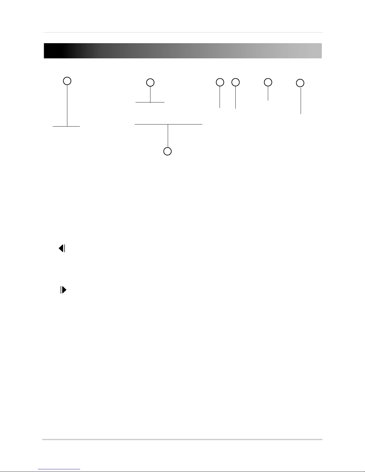
Front Panel
3
1
2
4 5 6
7
1 USB Ports: Connect a USB mouse (included) or USB thumb drive (not included) for backup or
firmware upgrades.
2 LED Indicators
• REC: Flashes when DVR is recording.
• POWER: Gl
3 Playback Buttons:
/ RELAY: In Playback mode, press to rewind. Press repeatedly to increase rewind speed.
•
• In Live Viewing mode, press to open the relay out control menu.
/ Info: In Playback mode, press to reverse video frame-by-frame.
•
• In Live Viewing mode, press to open the system information window.
•
/ Lock: In Playback mode, press to pause playback.
• In Live Viewing mode, press to Lock/Unlock the system controls.
•
/ Log: In Playback mode, press to advance video frame-by-frame.
• In Live Viewing mode, press to open the Log Viewer.
•
/ Play / Fast Forward: In Playback mode, press to start playback. Press repeatedly to fast
forward.
• In Live Viewing mode, press to open Playback mode.
4 MENU Button:
5 ESC Button: Pr
:
ows when DVR is on.
Press to access Main Menu.
ess to exit menus or Playback mode.
2
Page 19
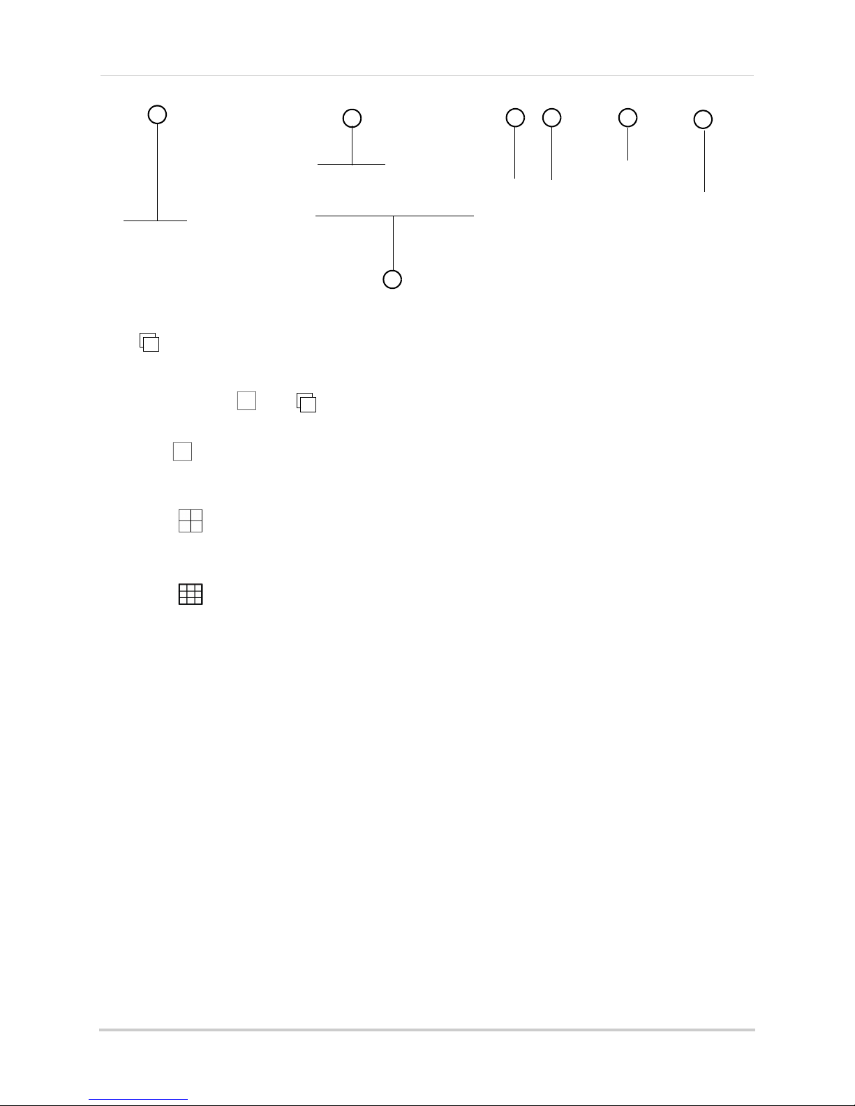
6 Navigation Buttons:
3
1
2
4 5 6
7
• : Press to confirm menu selections.
• In Full-screen Live Viewing mode, press to start Sequence view. In Sequence view, the
DVR
changes channels in full-screen every few seconds. If the DVR is in split-screen mode,
press
/ then to start Sequence view.
• Press again to end Sequence view.
/ : Press to scroll up in menus.
•
• In Live Viewing mode, press to select Full-screen mode. Press repeatedly to change
channels.
/ : Press to scroll left in menus.
•
• In Live Viewing mode, press to select Quad (4-way Split-screen) mode.
•
: Press to scroll down in menus.
/ : Press to scroll right in menus.
•
• In Live Viewing mode, press to select 9-way-split (8-channel models only).
ower Button:
7 P
Press to power the DVR on/off. Admin password required to power off.
3
Page 20
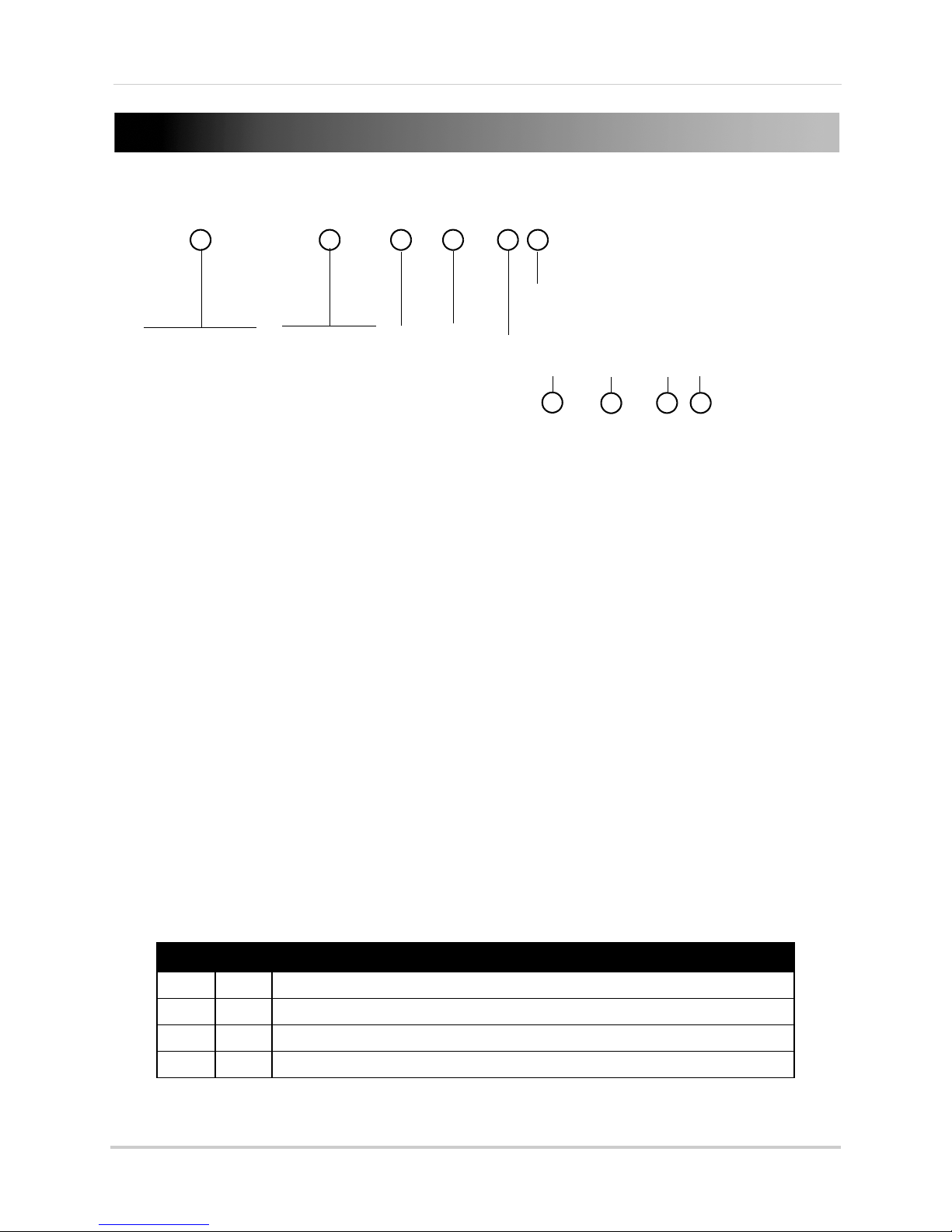
Rear Panel
6
54
7
1
8
9
2 3
10
4-Channel
1 CAMERA INPUTS: Connect up to 4 HD-SDI cameras.
2 AUDIO INPUTS: RCA audio inputs for up to 4 channels.
3 AUDIO OUTPUT: RC
4 VGA: Connect
VGA and HDMI monitor at the same time.
5 HDMI:
the D
6 eSATA: Connect
7 ETHERNET: Con
8 RS485/ALARM: Connect
included).
9 INPUT/OU
DVR to make changes using the INPUT/OUTPUT switches.
NOTE: It is recommended to set all INPUT/OUTPUT switches to the up (U) position for full HD
• 1 (NTSC/PAL):
• 2 (Video Input):
• 3 & 4 (Video Output):
Connect an HDMI TV/monitor (recommended) to view the system interface. Note that
VR cannot use a VGA and HDMI monitor at the same time.
TPUT Switches: U for up position; D for down position. You must shut down the
(
1080P) input and output.
1080p and 720p cameras.
table below.
A audio output for 1 output channel (e.g. speakers).
a VGA monitor to view the system interface. Note that the DVR cannot use a
an external hard drive (not included) using an eSATA cable.
nect a CAT 5 RJ45 Ethernet cable for local and remote connectivity.
compatible PTZ cameras (not included) or alarm sensor devices (not
Select U for NTSC (for North America, recommended) or D for PAL (for Europe).
Select U for 1080p camera input or D for 720p camera input. You cannot mix
Select the correct video output resolution for your monitor using the
3 4 Output Resolution
U U Full HD (1920x1080) - recommended for 1080p HDTVs/HDMI monitors
U D HD (1280x720) - recommended for 720p HDTVs/HDMI monitors
D U WSXGA+ (1680x1050)
10 DC12V: Connect the included AC power adapter.
4
D D SXGA (1280x1024) - recommended for VGA monitors
Page 21
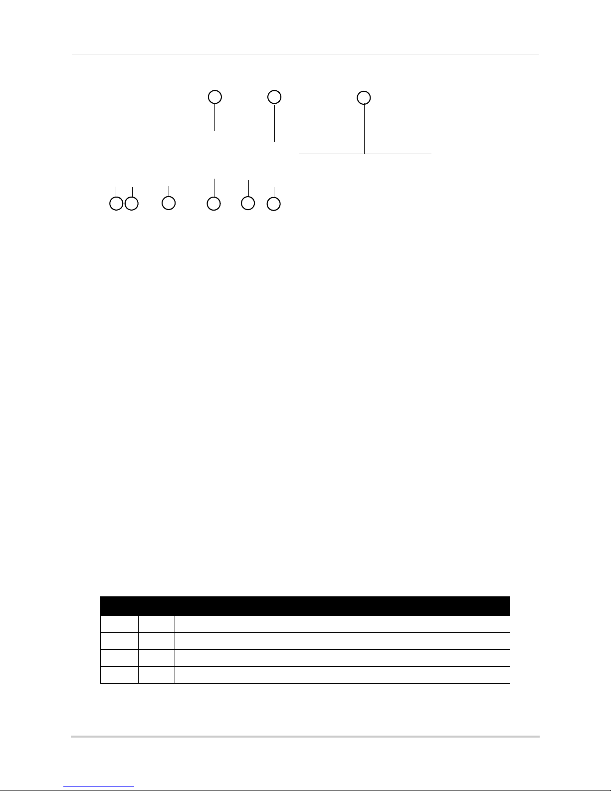
8-Channel
4
3
7
8
1 2
9
5
6
1 AUDIO/TV/SPOT: Connect the Audio / Video Octopus cable to enable 4 RCA audio inputs, 1
RCA audio output, and 1 BNC video output (TV) for connecting the DVR to an external BNC
monitor. For details on connecting external monitors, see “Appendix E: Connecting External
Monitors (8-Channel Only)” on page 143.
NOTE: Audio-ca
pable cameras (not included) or self-powered microphones (not included) are
required to use audio features.
2 eSATA: Connect an
3 CAMERA INPUTS: Connect
4 ETHERNET: Conn
5 HDMI: Connect
external hard drive (not included) using an eSATA cable.
up to 8 HD-SDI cameras.
ect a CAT 5 RJ45 Ethernet cable for local and remote connectivity.
an HDMI TV/monitor (recommended) to view the system interface. Note that
the DVR cannot use a VGA and HDMI monitor at the same time.
:
6 VGA
Connect a VGA monitor to view the system interface. Note that the DVR cannot use a
VGA and HDMI monitor at the same time.
7 RS485/ALARM:
Connect compatible PTZ cameras (not included) or alarm sensor devices (not
included).
o
8 INPUT/OUTPUT Switches: U f
r up position; D for down position. You must shut down the
DVR to make changes using the INPUT/OUTPUT switches.
NOTE: It is recommended to set all INPUT/OUTPUT switches to the up (U) position for full HD
080P) input and output.
(1
• 1 (NTSC
/PAL): Sel
• 2 (Video Input): S
ect U for NTSC (for North America, recommended) or D for PAL (for Europe).
elect U for 1080p camera input or D for 720p camera input. You cannot mix
1080p and 720p cameras.
• 3 & 4 (Video Output): Sel
ect the correct video output resolution for your monitor using the
table below.
3 4 Output Resolution
U U Full HD (1920x1080) - recommended for 1080p HDTVs/HDMI monitors
U D HD (1280x720) - recommended for 720p HDTVs/HDMI monitors
D U WSXGA+ (1680x1050)
D D SXGA (1280x1024) - recommended for VGA monitors
9 DC12V: Connect the included AC power adapter.
5
Page 22

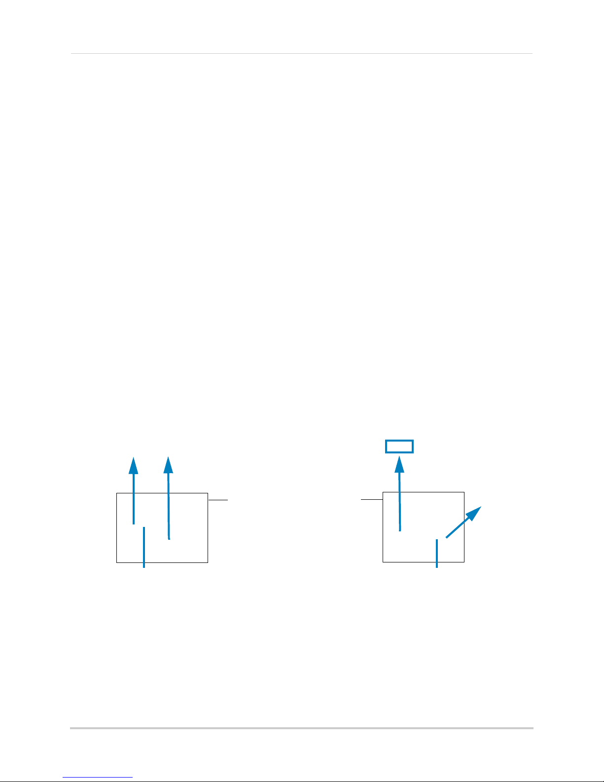
Basic Setup
Push and twist the BNC connector clockwise
to secure it to the BNC port.
USB ports
Basic Setup
Step 1: Connect the Cameras
• Connect the HD-SDI cameras to the CAMERA INPUTS ports on the rear panel of the DVR. For
details, see “Connecting Cameras” on page 10
.
NOTE: Make sure to include some slack in the extension cable on both ends when connecting
t
o the DVR. Strip lines may appear in the image if the cable is too tight.
Step 2: Connect the Mouse
• Connect a USB mouse (included) to one of the USB ports on the front panel of the DVR.
6
Page 23

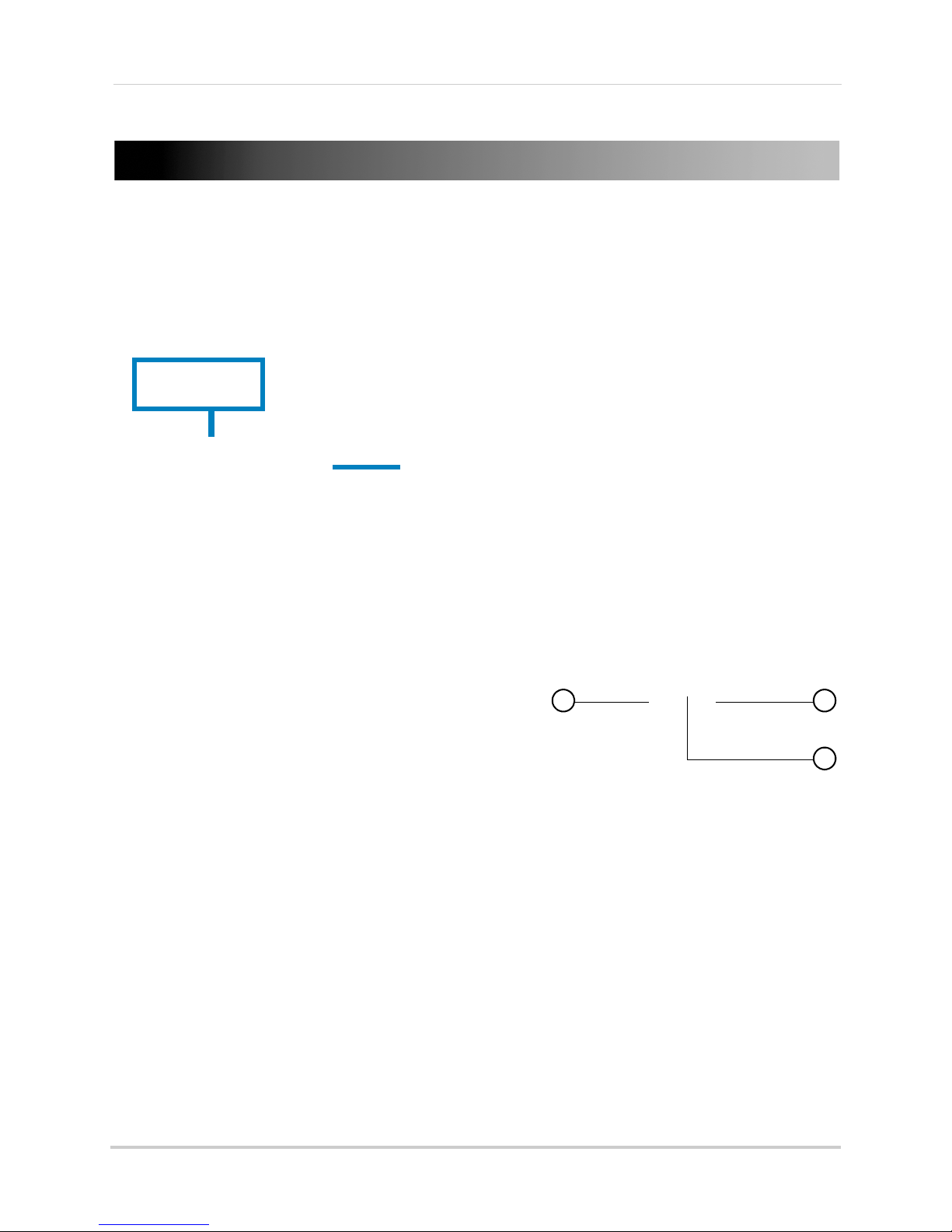
Step 3: Connect the Ethernet Cable
Connect ethernet cable
ETHERNET port
HDMI
VGA
• Connect an ethernet cable (included) to the ETHERNET port on the rear panel of the DVR.
Connect the other end of the ethernet cable to a router on your network.
Basic Setup
Step 4: Connect the Monitor
• Connect a HDMI cable (included) from the HDMI port to the TV or monitor (recommended) OR;
• Connect a VGA cable (not included) from the VGA port t
NOTE: The DVR cannot use an HDMI and VGA monitor at the same time.
NOTE: If you have a monitor with a DVI input, you must use an HDMI to DVI adapter (not included).
ou cannot use an DVI to VGA adapter.
Y
o the monitor.
7
Page 24

Basic Setup
DC12V
Port
Power button
Step 5: Connect the Power Adapter and Power on the DVR
1 Connect the included power adapter to the DC12V port. Connect the end of the power adapter
to a wall socket or a surge protector.
2 Press the power button on the front panel to power on the DVR.
NOTE: If there is no picture on the TV/monitor after the DVR starts up, or if the picture does
not fit on the screen, check that the #3 & 4 INPUT/OUTPUT switches on the rear panel
are set correctly for your monitor’s resolution (see page 4 for details). You must power
off your DVR before changes using the INPUT/OUTPUT switches. Changes will take
ect when y
eff
our DVR is powered back on.
Step 6: Verify Camera Image
• Power on the cameras, and then verify the camera video quality before mounting the cameras
to a permanent location.
• Mount the cameras under a sheltered location. Always verify the environmental rating of
ca
meras before installing in a permanent location.
Step 7: Set the Time
• Set the system date and time for accurate video time stamps. Videos with inaccurate times
may not be valid as surveillance evidence.
• For details on setting the system time, see “Setting the Date and Time” on page 19.
8
Page 25
Default System Password & Port Numbers
By default, the system user name is admin and the password is
00000. Passwords are disabled by default, but are required to
access certain system functions. It is recommended that you enable
passwords and create your own password. For details, see
“Managing User Accounts and Passwords” on page 77.
ALL the system port numbers below must be port forwarded on your router to log in to your
system over the Internet or an internal network (LAN).
DVR user name and password:
m
• User name: ad
in / Password: 00000
Basic Setup
DVR user name and password for remote connection using a c
• User name: adm
DVR user name and password for remote connection using
• User name: adm
Default ports for remote access:
• Port 80 (W
• Port 3000 (Client port)
eb port)
in / Password: no password; not required
in / Password: 00000
omputer:
a Smartphone or Tablet:
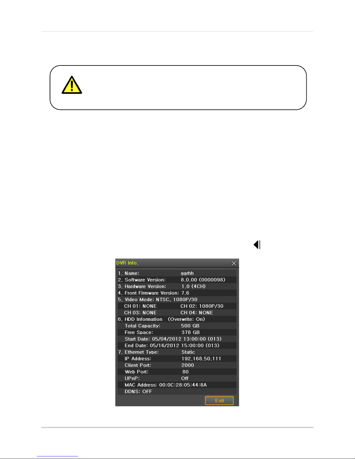
Quick Access to System Information
• To quickly open a window that displays vital system information, press on the front panel
or remote control.
9
Page 26

Connecting Cameras
ATTENTION: T his DVR is on ly comp atible with HD-SDI cameras; regular BNC came ras
will not work.
Cameras differ in terms of installation or mounting instructions. Please see
the documentation that came with your camera(s) for specific installation instructions.
Connecting Cameras
About HD-SDI
HD-SDI is a standard for transmitting un-compressed, high definition video along
high-grade coaxial cables (such as RG59). It uses digital signals that carry large amounts
of information (over 1Gbit/second).
Because HD-SDI video systems use digital signals, they are incompatib
cameras and DVRs, which transmit video using analog signals, that are commonly used in
video surveillance applications. This means that you cannot use non-HD-SDI security
cameras with an HD-SDI DVR, and you cannot use HD-SDI cameras with a non-HD-SDI
DVR.
le with
traditional
Installation Warnings
• Use the included extension cables or visit www.lorextechnology.com for compatible RG59
extension cables.
• The extension cable must be a single stretch of cable between the DVR and camera. You
ca
nnot connect multiple extension cables to each other.
• You cannot mix 1080p and 720p HD-SDI cameras. All ca
be either 1080p or 720p.
meras connected to the system must
Installation Tips
• Mount the camera where the lens is away from direct and intense sunlight.
• Plan your cable wiring so that it does not interf
• Ensure that the camera wiring is not exposed or easily cut.
• Mount the camera in an area that is visibl
• Avoid poi ntin g the ca mera at a gla ss windo w to see outside, as this may result in a
caused by glare from indoor / outdoor lighting conditions.
• Adjust the camera angle so that it covers an area with high traffic.
• In "high-risk" locations, have multiple cameras point in the same area. This provides camera
dundancy if a vandal attempts to damage the camera.
re
ere with power lines or telephone lines.
e, but out of reach.
poor image
Installing Cameras
Test the cameras before permanent installation. Plan where you will route the wiring for
the camera and where you will aim the camera.
To install cameras:
a
1 Mount the c
with the camera(s). Choose a firm mounting surface.
NOTE: If you wish to mount cameras to drywall, it is r
10
mera(s) to the desired mounting surface according to the instructions that came
ecommended to use drywall plugs (not
included).
Page 27
Connecting Cameras
Table Mount Wall Mount Ceiling Mount
Camera model not be exactly as shown
RG59 Extension cable
Female power connector
To Digital Video Recorder:
(4-channel model shown)
Male power connector
BNC
To Camera:
2 Adjust the camera stand to ensure that the camera has a satisfactory view of the area you
would like to monitor. Stand configuration depends on the mounting surface you have chosen
(see below for suggested stand configurations).
Connecting HD-SDI Cameras to your DVR
1 Connect the BNC connector on the camera to the RG59 extension cable.
2 Connect the male power connector on the RG59 extension cable to the female power
c
onnector on the camera.
3 Connect the BNC connector on the other end of the RG59 extension cable to one of the
ERA INPUTS ports on the rear panel of the DVR.
CAM
NOTE: Make sure to include some slack on the extension cable at both ends when connecting
the c
amera to the DVR. Strip lines may appear in the image if the cable is too tight.
4 Connect the female power connector on the RG59 extension cable to the power adapter.
5 Plug the camera power adapter to a power outlet.
Camera Connection Diagram
Connecting and Removing BNC Cables
BNC (Bayonet Nut Connector) is a special connector that locks on to the system port and
cannot be accidently removed.
To connect or remove a BNC connector:
• Push the BNC connector firmly into the BNC port and simultaneously twist the connector
clockwise t
o tighten.
• To remove a BNC connector from a BNC port, push and simultaneously twist the connector
er-clockwise to loosen the BNC connector.
count
11
Page 28
Mouse Control
USB ports
1 2
3
Mouse Control
The DVR is designed for mouse navigation. To use a USB mouse (included), connect the
mouse to a USB port on the rear panel of the DVR.
Use the mouse buttons to perform the following:
1 Left-Button:
• Click to select a menu option. In Split-screen view,
double-click on
channel in full-screen; double-click the channel
again to return to Split-screen view
2 Right-Bu
• In Live Viewing mode, click to open the Main Menu
(see “Using the Main Menu” on page 29).
• In Playback mode, click to open the Playback
sub-menu (see “Playback Sub-Menu” on page 24).
3 Scroll-Wheel:
• In Zoom mode, scroll up/down to adjust the zoom
le
page 18.
tton:
v
el. For details, see “Using Zoom Mode” on
a channel to view the selected
.
12
Page 29
Remote Control
3
4
6
5
2
1
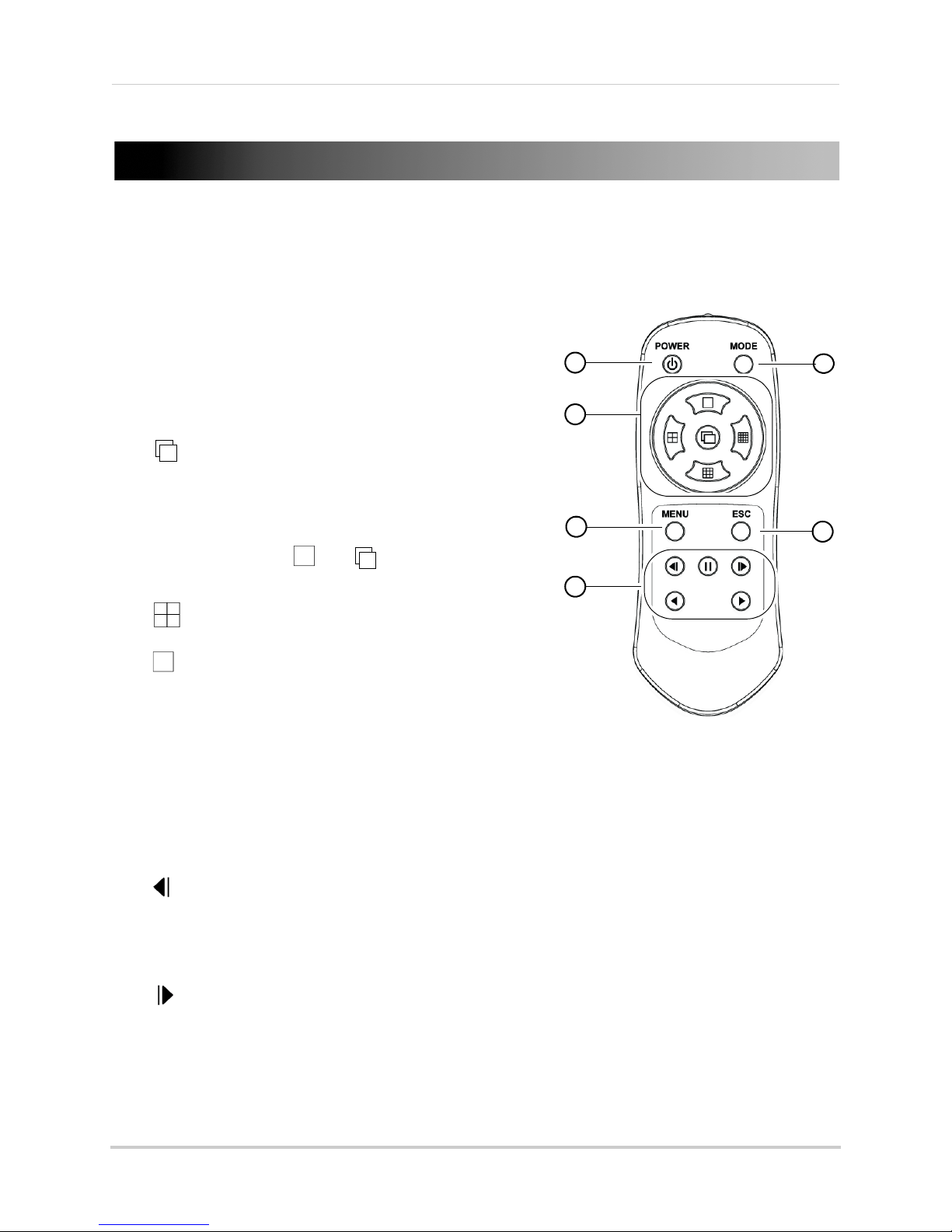
You can also control the DVR using the included remote control.
4-Channel Remote Control
1 POWER: Press to power the DVR on / off. Admin
password required to power the DVR off.
2 MODE: No function.
Remote Control
3 Navigati
the outside buttons to move the cursor.
•
•
split-screen) mode.
•
4 MENU: Pr
sub-menu.
5 ESC: Pr
• Press to exit Playback mode and return to Live Viewing mode.
6 Playback Contro
/ Rewind: In Playback mode, press to rewind. Press repeatedly to increase rewind speed.
•
•
/ Lock: In Playback mode, press to pause playback.
•
on Buttons / View Selectors: In menus, press
: In menus, press to confirm menu selections.
• In Full-screen live viewing mode, press to start
Sequenc
changes channels in full-screen every few
seconds. When Split-screen live viewing mode is
selected, press
• Press again to end Sequence view.
: In Viewing mode, press to open Quad (4-way
: In Viewing mode, press to open Full-screen view.
• In Live Viewing mode, press to open the relay out control menu.
/ Info: In Playback mode, press to reverse video frame-by-frame.
• In Live Viewing mode, press to open the system information window.
• In Live Viewing mode, press to Lock/Unlock the system controls.
e view. In Sequence view, the DVR
then t o s t a r t S e q u e n c e v i e w .
ess to open the Main Menu or Playback
es
s to exit menus.
ls:
/ Log: In Playback mode, press to advance video frame-by-frame.
•
• In Live Viewing mode, press to open the Log Viewer.
/ Play / Fast Forward: In Playback mode, press to start playback. Press repeatedly to fast
•
forward.
• In Live Viewing mode, press to open Playback mode.
13
Page 30
Remote Control
1
2
4
5
6
7
8
9
11
12
3
10
13
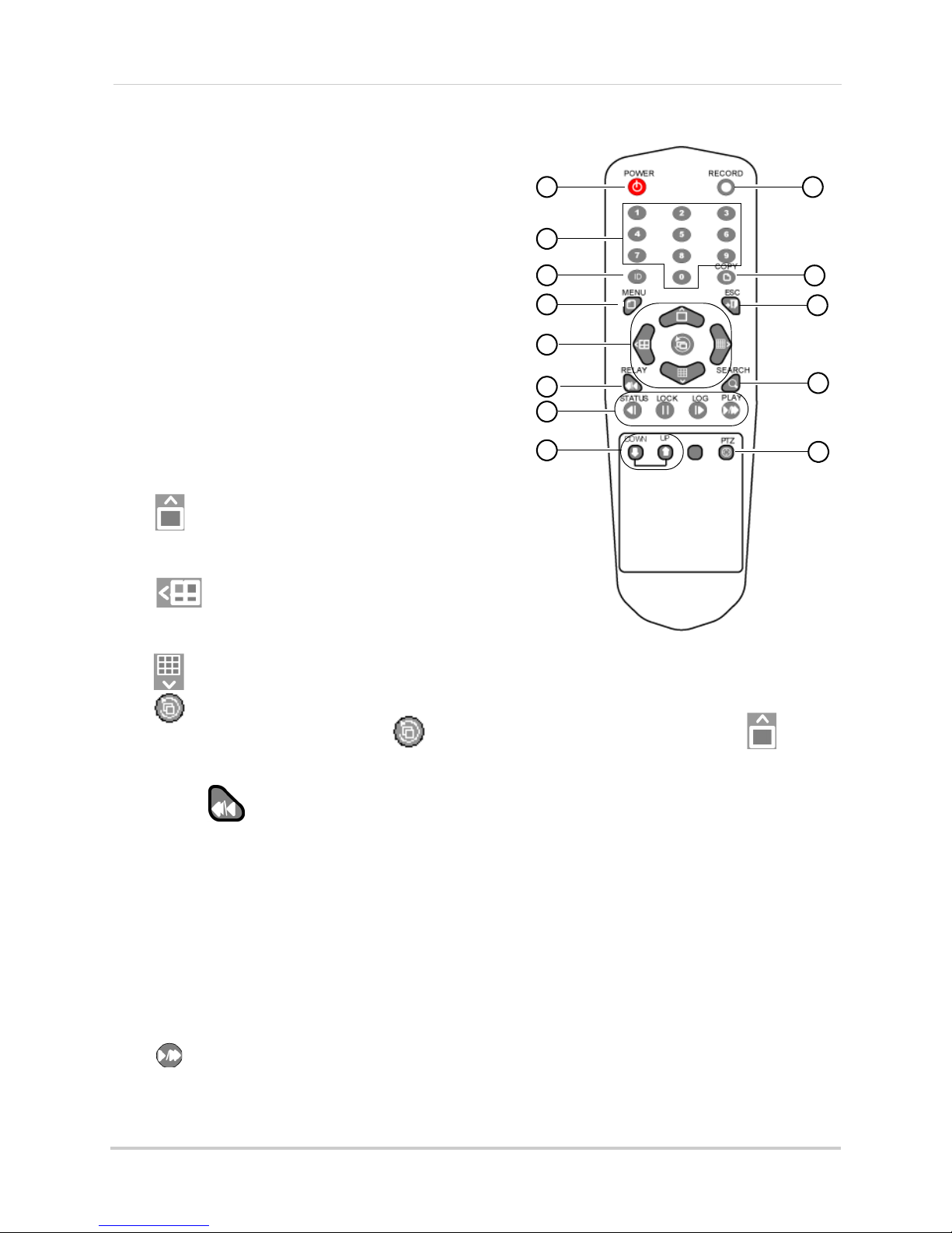
8-Channel Remote Control
1 POWER: Press to power the DVR on / off. Admin
password required to power the DVR off.
2 Numerical Keys: In
Live Viewing mode, press 1~8
to select channels in full-screen.
• In menus, press to input numerical values.
3 ID: Used t
o pair the
remote control to a specific
DVR. See “Changing the Remote Control ID
(8-Channel Only)” on page 15.
4 MENU
: In Liv
e Viewing mode, press to open the
Main Menu
• In Playback mode, press to open the Playback
Sub-menu.
5 Direction Keys: Pr
•
: In Live Viewing mode, press to open
ess to move the menu cursor.
full-screen / single-channel mode. Press
re
peatedly to change channels.
•
: In Live Viewing mode, press to open Quad
mode. Press repeatedly to switch between CH1~4,
5~8.
•
: In Live Viewing mode, press to open 9-way-split.
•
: Press to confirm menu selections.
• In Live Viewing mode, press
when full-screen mode is selected (press to open
full-screen mode) to start/stop Sequence mode.
6 RE
7 Playback c
LAY /
• In Playback mode, press to rewind. Press repeatedly to increase rewind speed.
o
ntrols:
•
| / STATUS: Reverse video frame-by-frame.
: In Live Viewing mode, press to open the relay out menu.
• In Live Viewing mode, press to access system information.
•
/ LOCK: Pause.
• In Live Viewing mode, press to lock/unlock the system controls.
/ LOG: Advance video frame-by-frame.
• |
• In Live Viewing mode, press to access system logs.
/ PLAY: Play / fast forward.
•
• In Live Viewing mode, press to open Playback mode.
14
Page 31

Remote Control
1
2
4
5
6
7
8
9
11
12
3
10
13
Click and enter a
unique ID number
Press ID, then the 2 digit ID number, then press ID again
8 DOWN / UP:
Press to switch to the next/previous
page in the log.
9 RE
CORD: Pr
ess to stop/resume recording on all
channels. Admin password required.
es
10 COPY: Pr
s to open the Backup Menu. See
“Backup” on page 62.
11 ESC: Exit menus or Playback Mode.
12 SEARCH: Open the Sear
ch Menu. See “Search”
on page 60.
13 PTZ: Pr
r
equired; not included).
ess to open PTZ controls (PTZ camera
Changing the Remote Control ID
(8-Channel Only)
The remote control ID allows you to pair the DVR
to a particular remote control. This is useful if you
have more than one DVR.
To pair the remote control to the DVR:
rom Live Viewing mode, right-click to open the
1 F
Ma
in Menu. Click Setup then System.
2 Click ID f
or Remote Controller. Enter a unique ID
number for the DVR, and then click Save & Exit.
3 Click Save to save changes. Click Exit to return to Live Viewing mode.
4 On the remot
e control, press ID. Then enter the ID you created as a 2 digit number (e.g. if the
ID is "5," enter "05." Then press ID again. The remote control will now be paired to the DVR.
15
Page 32

Using the On-Screen Display
12
3
4
4-channel model shown
4-channel
8-channel
Using the On-Screen Display
Use the system’s graphical on-screen display to navigate Live Viewing mode.
1 Channel Number/Name
2 Audio Indicator:
Shows the channel that the DVR is currently playing audio from.
Audio-enabled cameras (not included) or self-powered microphones (not included) are
required for audio. For more information on audio, see “Appendix C: Recording Audio” on
page 135.
3 Rec
ording Icons: Sho
ws the recording status for the channel. For details, see “Recording and
Events” on page 22.
wi
4 Live Vie
ng Toolbar:
• ID: (8-channel models only) Shows the remote control ID for the DVR. For details, See
“Changing the Remote Control ID (8-Channel Only)” on page 15.
: Click once to select Full-screen view. Click repeatedly to change channels.
•
: Click to select Quad (4-way-split-screen) mode.
•
: Click to select 9-way-split (8-channel models only).
•
16
Page 33

Using the On-Screen Display
• : Click to enter Zoom mode. For details, see “Using Zoom Mode” on page 18.
: When in Full-screen view, click to begin Sequence view. In Sequence view the DVR
•
switches channels every few seconds. If the If the DVR is in Split-screen view, click
to start Sequence view.
• Click
• Date and Time: Displays
• Hard Drive Status:
again to exit Sequence view.
the system date and time. Time is shown in 24hr. format.
Shows the hard drive status. Shows OverWt. if overwrite is enabled. Shows
the remaining free hard drive space if overwrite is disabled.
• PLAY: C
lick to enter Playback mode.
Using the Virtual Keyboard
You can input numeric or text values using the on-screen virtual keyboard. For example,
the virtual keyboard is used when creating custom names for cameras or the DVR.
then
To use the Virtual Keyboard:
1 In menus, click or
double-click on a field.
• The Virtual Keyboard opens.
• Click Caps Lock
• Click < to dele
• Click Space to
• Click Cance
• Click Save & Exit
to switch between upper case and lower case letters.
te a character.
create a space.
l to exit the Virtual Keyboard without changing the selected field.
to change the selected field.
17
Page 34

Using the On-Screen Display
Click inside the box to change the zoom area.
Use the mouse wheel to zoom in and out.
Using Zoom Mode
Zoom mode allows you to zoom in on an image while viewing your cameras live or playing
back recorded video. This can be useful if you want to get a closer look at a situation.
To use the Zoom mode:
1 In Live viewing or Playback mode, click
to enter Zoom mode.
2 Click the channel you would like to zoom in on. The channel opens in Full-screen view and
the DVR zooms in on the image. A box on the bottom-right of the screen opens to show the
entire image, with the zoomed in area highlighted with a yellow box.
• Click inside the box on the bottom-right to change the zo
double-click inside the box to zoom in and out.
3 Right
-click or click ESC t
mode.
18
om area. Use the scroll wheel or
o exit Zoom mode and return to Live viewing mode or Playback
Page 35

Setting the Date and Time
It is highly recommended to set the date and time when first
setting up your system.
Inaccurate time stamps may render your footage unusable for
court evidence.
Double-click the sections of
the date and time you would
like to change.
Click the up and down
arrows to set the date and
time.
Click Save
To set the date and time:
1 In Live Viewing mode, right-click on the screen and click Setup. Sel
ect the Date & Time tab.
2 Under Date & Time, double-click the sections of the date or time you would like to change,
and then click the up and down arrows to set the date and time.
NOTE: Time is display
3 Click Sav
e to save your changes. Click Exit to return to Live Viewing mode.
ed in 24-hour format.
19
Page 36

Configuring Daylight Savings Time (DST)
Select your time zone
Select On
Configure a custom start
and end time for Daylight
Savings if needed
Click Save
If your region observes Daylight Savings Time (DST), follow the instructions below to
configure your DVR to automatically update the time when the clock updates.
To enable automatic DST adjustments:
1 In Liv
e Viewing mode, right-click on the screen and click Setup.
2 Click Time and select the Time Zone tab.
3 Click the field next t
4 Click the field next t
• If you need to change the date and time that Daylight Saving
o Time Zone and select your time zone.
o Daylight Saving Time and select On.
s starts and ends, click the fields
next to Start Time and End Time. Make any required changes and click Save.
5 Cl
ick Sav
e to save your changes and click Exit return to Live Viewing mode.
20
Page 37

Setting the Date and Time
Select NTP
Click Save
Using a NTP Server to set your System Time
A NTP (Network Time Protocol) server syncs your system time with an online time server.
NOTE: A constant Internet connection is required to use the NTP feature.
enable NTP:
To
1 Right-click to open the Main Menu. Click Setup then
Time. Select the Time Sync tab.
2 Under Time Sync, select NTP.
3 Click Sav
e. Wait for the system time to update. Click Ok then Exit to return to Live Viewing
mode.
21
Page 38

Recording and Events
Recording Icons
Recording and Events
By default, the system is set to immediately record video from connected cameras in
Continuous Recording mode. The DVR supports the following recording types, which are
represented by icons in the On-screen Display when enabled or activated.
• — Continuous Recording: The DVR records all video. The icon shown is green if the DVR
is recording or white if the DVR is not recording.
— Motion Event Recording: The DVR records when motion is detected. The icon shown
•
will be white if motion detection is enabled, a
•
— Sensor Event Recording: The DVR records when triggered by an external alarm or
sensor device (not included). The icon shown will be white if sensor rec
red when sensor recording is triggered.
— Audio Event Recording (4-Channel Only): The DVR records when audio is detected.
•
Audio-enabled cameras (not included) or self-powered microphones (not included) must be
connected
enabled, and red when audio events are triggered.
Events are created when Motion Event, Sensor Event, and Audio Event Recording are
triggered. Event
• See “Event Playback” on page 28.
• See “Search” on page 60.
You can create a custom recording schedule that enables different recording types at
different
records when motion is detected outside of business hours).
to use audio recording. The icon shown will be white if audio event recording is
s allow
s (for example, that records continuously during business hours but only
time
you to quickly find relevant footage.
nd red when motion recording is triggered.
ording is enabled, and
• See “Recording” on page 35.
• See “Schedule” on page 43.
22
Page 39

Playback
4-channel model shown
1
2
3
4
5 7
8
6
4-channel model shown
You can view recorded video on the system using Playback mode. You can access Playback
mode from Live Viewing mode, or use the Search options or Log Viewer to select video from
a certain time or event.
om
To access Playback mode fr
• Click PLAY on
the Live Viewing toolbar. Playback mode opens.
Live viewing mode:
Playback
Playback Toolbar
1 : Click to select Full-screen view. Click repeatedly to change channels.
2
3
: Click to select Quad (4-way-split-screen) mode.
•
: Click to select 9-way-split (8-channel models only).
: Click to enter Zoom mode. For details, see “Using Zoom Mode” on page 18.
23
Page 40

Playback
4 Playback Bar: Shows times that the DVR has recorded video on the channel or channels in
green. Click inside the bar to change the playback time.
5 Date a
6 Playback Speed: Show
7 Playback Contro
•
•
•
•
•
8 LIVE: Click t
nd Time: Sho
: Click to rewind. Click repeatedly to increase rewind speed.
: Click to reverse video frame-by-frame.
: Click to pause.
: Click to advance video frame-by-frame.
: Click to play. Click repeatedly to fast forward.
o return to Live Viewing mode.
ws the time of the video currently being played.
s the playback speed selected.
ls:
Playback Sub-Menu
During Playback mode, right-click on the screen to access the Playback sub-menu. From
the Playback sub-menu, you can access playback modes and Calendar Search.
The Playback sub-menu has the following options:
• Smart Search: Searches the selected hour of video for footage that has movement.
• Panorama Playback: Plays back
time in split-screen.
• Calendar Search: Sear
page 60.
• Multi Time: Plays back av
• Multi Day: Plays back av
recorded at the same time of day.
• Multi Channel: F
mode, which shows video from multiple channels in split-screen.
• Event Playback:
• Backup: Click
details, see “Backup” on page 62.
• Zoom: See “Using
rom Multi Time and Multi Day Playback modes, return to the default playback
Backup to open the backup menu. Click Capture to take a screen shot. For
ch for recorded video from a specific date and time. See “Search” on
ailable video from previous hours at the same time in split-screen.
ailable video from previous days in split-screen, using footage
Plays footage recorded during events of the selected type.
Zoom Mode” on page 18.
multiple video frames from the selected channel at the same
Smart Search
Smart Search searches the selected hour of video for footage that has movement. This is
useful if you want to search large amounts of video and only show footage when something
is happening.
24
Page 41

To perform a Smart Search:
Playback Toolbar in Smart Search — Times where there is movement
are shown in green; times without movement are shown in black
Panorama Playback — Plays back multiple frames from the same video
1 From Playback mode, right-click on the screen and select Smart Sear
ch. Select the channel
you want to search (in Full-screen view, the DVR searches the full-screen channel). The DVR
performs a search on the hour of video selected.
Playback
NOTE: Use the Cal
2 Press
to start playback. Playback shows video with movement only and skips segments
endar Search option to select a different date or time to Smart Search.
with no movement.
• To exit Smart Search, click ESC on the Playback toolbar.
Panorama Playback
Panorama Playback allows you to view multiple frames from a recorded video at the same
time in split-screen. This can help you get a closer look at a sequence of events.
To use Panorama Playback:
1 From Playback mode, right-click on the screen and select Pa
channel you want to Playback (in Full-screen view, the DVR plays back from the full-screen
channel).
• Playback begins in slow motion and shows a different frame from the video in each section
of the scr
o exit Panorama Playback, click ESC on
2 T
een.
norama Playback. Select the
the Playback toolbar.
25
Page 42

Playback
Multi-Time Playback — Plays back video from previous hours simultaneously
Labels in the corners show the hour
video was recorded. Icons show the type
of recording at that time.
Multi-Time Playback
Multi-Time Playback plays video from previous hours simultaneously. The video shown is
from the same time for each hour (for example, if you are playing back a video recorded at
8:30, the DVR will play video from 8:30, 7:30, 6:30, etc.).
To use Multi-Time Playback:
1 From Playback mode, right-click on the screen and select Mul
ti Time. Select the channel you
want to playback.
• Playback begins showing footage from previous hours on screen. To change the date or time
fo
r playback, right-click and select Calendar Search.
o exit Multi-Time Playback, click ESC on
2 T
the Playback Toolbar.
26
Page 43

Playback
Labels in the corners show the date video
was recorded. Icons show the type of
recording at that time.
Multi-Day Playback — Plays back video from previous days simultaneously
Multi-Day Playback
Multi-Day Playback plays video from the previous day simultaneously. The video shown is
from the same time for each day (for example, if you are playing back a video recorded at
8:30 on May 5, the DVR will play video from 8:30 on May 5, May 4, May 3, etc.).
To use Multi-Day Playback:
1 From Playback mode, right-click on the screen and select Mul
ti Day. Select the channel you
want to Playback.
• Playback begins showing footage from previous days on screen. To change the date or time
for playback, right-click
o exit Multi-Time Playback, click ESC on
2 T
and select Calendar Search.
the Playback Toolbar.
27
Page 44

Playback
Click the type of event you
would like to playback
Event Playback Toolbar — Times with footage of the selected event type are show n in green.
Event Playback
Event Playback plays back video of the chosen event type (Motion, Sensor, or Audio) only.
To use Event Playback:
1 From Playback mode, right-click on
event (Motion, Sensor, or Audio) you want to playback.
the screen and select Event Playback. Click the type of
NOTE: Audio ev
ents not supported on 8-channel models.
• The DVR plays back footage from the selected event type only. The Playback toolbar shows
times with events of the selected type in green. Times are highlighted for all channels shown
in split-screen, or for the single channel shown in full-screen.
2 To exit Event Playback, right-click on the screen, select Event Playback, and click All.
28
Page 45

Using the Main Menu
1 2 3 4 5 6 7
To open the Main Menu:
• From Live Viewing mode, right-click or press the MENU butt
control to open the Main Menu.
Using the Main Menu
on on the front panel or remote
NOTE: If pas
open the Main Menu.
1 Log-in / Log-out: Log-in to the DVR using your user name and password or log-out of the
DVR (only shown when passwords are enabled).
2 Setup: Configure the DVR date and time, camera settings, recording parameters, recording
schedul
flash drives for recording and backup. Install firmware updates and restore to factory
defaults.
3 Search: Sear
4 Backup: Backup re
5 PTZ Control: Controls f
Camera” on page 130.
words are enabled on the system, you must enter the appropriate password to
s
e, network settings, user accounts, and system settings. Format hard drives and
ch f
or recorded video on the DVR.
corded video or take screen captures (screenshots).
or PTZ cameras (not included). See “Appendix B: Connecting a PTZ
6 Zoom: Opens Zoom mode. F
7 Miscellaneous: Ac
Configure interface settings. Shutdown the DVR.
cess System Information window, Log Viewer, and miscellaneous controls.
or details, see “Using Zoom Mode” on page 18.
29
Page 46

Setup
Select date display format
Click Save
Setup
Configure the DVR date and time, camera settings, recording parameters,
recording schedule, network settings, user accounts, and system settings.
Format hard drives and flash drives for recording and backup. Install firmware
updates and restore to factory defaults.
Time
Set DVR date and time, change the Date Display format, enable/disable Auto Reboot.
• To set the date and time, see “Setting the Date and Time” on page 19.
Changing the Date Format
1 Right-click to open the Main Menu, click Setup then Time. Select the Date & Time tab.
2 Click the Date Displ
dd/yy, yy/mm/dd).
3 Click Save to save your changes. Click Exit to return to Live Viewing mode.
ay Type drop-down and select the desired date format (dd/mm/yy, mm/
Enabling Auto Reboot
Auto Reboot automatically restarts the DVR on a daily or weekly basis. Restarting the
system every so often ensures system stability.
30
Page 47

To enable Auto Reboot:
Select On
Select the time for reboot
Select Every Day to reboot daily
or select the time of the day the
DVR will reboot on
Click Save
1 Right-click to open the Main Menu, click Setup then
Time. Select the Auto Reboot tab.
2 Under Auto Reboot, select On to turn on Auto Reboot.
Setup
3 Under Time, select th
4 Under Repeat, sele
e hour you would like the DVR to restart at.
ct Every Day to have the DVR restart daily, or select which day of the week
you would like the DVR to restart on.
5 Click Sav
e to save your changes. Click Exit to return to Live Viewing mode.
Camera
Configure camera titles and settings.
To configure PTZ cameras (not included), see “Appendix B: Connecting a PTZ Camera” on
page 130.
Disconnecting/Connecting Cameras
When cameras are connected to the DVR, they are automatically connected to the system.
When camera cables are disconnected, a Video Loss icon is shown. To hide the Video Loss
icon, you must disconnect the cameras in the Camera tab.
If a connected camera is not appearing on screen, check the Camera tab to ensure that it
l
is connected. A
To disconnect/connect cameras:
1 Rig
ht-click to open the Main Menu, and click Se
2 Select the Camera ta
so check under Live Covert and ensure it is set to Off.
tup then Camera.
b.
3 Under Connect n
ext to the channel you want to configure, select Off to disconnect the camera
or On to connect the camera.
ick Sav
4 Cl
e to save your changes and click Exit to return to Live Viewing mode.
31
Page 48

Setup
Double-click to create a
custom camera title
Click Save
Double-click to enable
covert recording
Click Save
Creating Custom Camera Titles
You can rename your cameras with custom titles.
To create custom camera titles:
1 Right-click to open the Main Menu, and click Setup then Camer
a.
2 Select the Camer
a tab.
3 Double-click under Name next to the channel you want to configure, and use the on-screen
keyboard to enter a title for the channel. Click Save & Exit when finished.
e to
4 Click Sav
save your changes. Click Exit to return to Live Viewing mode.
Enabling Covert Recording
Covert recording hides individual channels so that it seems like the DVR is not recording.
Covert channels are only visible when the admin account is logged in to the DVR through a
remote connection (i.e. over the Internet or a LAN).
To enable covert recording:
1 Right-click to open the Main Menu, and then click Setup.
2 Select the Camer
3 Double-click under Live Covert for the channel you want to hide and select On.
32
a tab.
Page 49

4 Click Save to save your changes then click Exit to return to Live Viewing.
Double-click
to change the
Motion
Sensitivity
Setting Motion Detection Sensitivity
Motion Sensitivity determines how easily motion detection events are triggered. Higher
Motion Sensitivity means that less motion is required to trigger a motion event.
Motion Sensitivity must be configured for each camera, and motion events
in the Recording Menu before the DVR will record for these events.
To change Motion Sensitivity:
rom Live Viewing mode, right-click to enter the Main Menu and select Setup. Cl
1 F
and select the Event Source tab.
must be enabled
ick Camera
2 Double-click under Motion Sensitivity for each camera to set the motion detection sensitivity.
3 Click Sav
e to save your changes and click Exit to return to Live Viewing mode.
Setting Sensitivity for Audio Events (4-Channel Only)
Sound Sensitivity determines how easily audio events are triggered. Higher Sound
Sensitivity means quieter sounds will trigger audio events.
NOTE: Audio e
Sound Sensitivity must be configured for each camera, and audio events must
in the Recording Menu before the DVR will record for these events.
vents are not supported on 8-channel models.
be enabled
33
Page 50

Setup
Double-click
to change the
Sound
Sensitivity
To change Sound Sensitivity:
1 From Live Viewing mode, right-click to enter the Main Menu and select Se
and select the Event Source tab.
tup. Click Camera
2 Double-click under Sound Sensitivity to set the sensitivity for audio events.
3 Click Save to
save your changes, and click Exit to return to Live Viewing mode.
Configuring Motion Detection Areas
Motion Detection Areas allow you to enable or disable motion detection in certain areas.
For example, you can disable motion detection where your camera overlooks a public
street and enable motion detection to trigger when someone enters your driveway.
You must enable Motion Events in the Recording Menu to enable motion recording.
To configure Motion Detection Areas:
1 From Live Viewing mode, right-click to enter the Main Menu and click Se
2 Click Camera
and select the Event Source tab.
tup.
34
Page 51

3 Double-click under Motion Area for the channel you want to configure. The Motion Area
Double-click
to configure
motion
detection
areas
Transparent:
Motion Detection
disabled
Blue: Motion
Detection Enabled
configuration screen appears.
Setup
4 Click and drag inside the grid to configure Motion Areas. Areas where motion detection is
enabled are highlighted in blue. Areas where motion detection is enabled are transparent. A
light blue outline appears in areas where motion is currently detected.
5 When finished, right-click and select Exit to return to the Event Source tab. Click Save to save
your changes and then click Exit to return to Live Viewing mode.
Recording
Configure recording settings and enable motion, sensor, and audio events.
NOTE: Audio ev
ents are not supported on 8-channel models.
Settings in the Recording menu are divided into recording schedules to enable the DVR to
35
Page 52

Setup
Recording schedules
By default, Schedule1 is enabled 24/7
Double-click to
select On to turn on
motion detection.
Click Save
automatically change the recording settings at different times. By default, Schedule1 is
enabled 24/7. For instructions on how to select when schedules are used, see “Schedule”
on page 43.
Click the schedule to configure recording settings for that schedule.
Enabling Motion Detection/Motion Events
You must enable motion detection on each channel before the DVR will save motion events.
To enable motion detection/motion events:
1 From Live Viewing mode, right-click to open the Main Menu. Click Setup then Rec
2 Select the Event tab
.
3 Under the channels you want to enable motion detection on, double click under Motion and
select On to turn on motion detection.
ording.
4 Cl
ick Sav
e to save your changes and click Exit to return to Live Viewing mode.
Configuring the DVR for Motion Recording Only
You can configure the DVR to record only when motion is detected. This allows you to
extend the amount of recording time by stopping recording when there is nothing
36
Page 53

happening.
Double-click to
select On to turn on
motion detection
Click Save
Set Continuous Speed to Off
to disable recording when
motion is not detected
Click Save
Setup
To configure the DVR for mo
NOTE: This method assumes that Schedu
tion recording only:
le1 is enabled 24/7, which is the default setting. For
more information, see “Schedule” on page 43.
1 From Live Viewing mode, right-click to open the Main Menu. Click Setup t
2 Select the Recording ta
3 Under all c
onnected channels, double click under Motion and select On to turn on motion
b.
detection.
hen recording.
4 Click Save to save your changes.
5 Select the Recording ta
6 Under Continuous Speed f
b.
or all connected channels, select Off. This disables continuous
recording so the DVR will only record when motion is detected (or for other event types if they
are enabled).
7 Click Save to save your changes. Click Exit to return to Live Viewing mode.
37
Page 54

Setup
Double-click to
select On to turn
on Sensor Events
Click Save
Double-click to
select On to turn
on audio events
Click Save
Enabling Sensor Events
Sensor Events trigger recording when an external sensor device (not included) is
triggered.
To enable sensor events:
rom Live Viewing mode, right-click to open the Main Menu. Click Setup then Rec
1 F
ording.
2 Select the Event tab
.
3 Under the channel you want to enable sensor events on, double click under Sensor and
select On to turn on Sensor Events.
Click Save to
save your changes and click Exit to return to Live Viewing mode.
Enabling Audio Events (4-Channel Only)
You must enable audio events for each channel before the DVR will save audio events.
Audio-enabled cameras (not included) or self-powered microphones (not included) are
required to use Audio Events
To enable audio events:
1 From Live Viewing mode, right-click to open the Main Menu. Click Setup then Rec
2 Select the Event tab
38
.
ording.
Page 55

Setup
8-Channel Model:
Select recording
resolution using
switch #2:
Up: 1080p
Down: 720p
Double-click to select
recording resolution
Double-click to select
recording quality
Click Save
3 Under the channel you want to enable audio events on, double click under Audio and select
On to turn on audio events.
4 Cl
ick Sav
e to save your changes, and click Exit to return to Live Viewing mode.
Changing the Recording Resolution and Quality
The recording resolution and quality affects the quality and frame rate of recorded images.
Increasing the resolution or quality will provide a better image, but will reduce the
maximum frame rate available.
NOTE: On 8-channel models,
recording resolution using the menu. To change the
recording resolution on 8-channel models, power
off the DVR by pressing the power button and
entering the admin password (default: 00000).
Then change the #2 INPUT/OUTPUT switch to Down
for 720p or Up for 1080p. When you power the DVR
on, the resolution setting for all cameras will be set
to your selection.
To change the recording resolution and quality:
1 From Live Viewing mode, right-click to open the Main Menu. Click Setup then Rec
2 Select the Recording ta
you cannot change the
b.
ording.
3 4-Channel Only: Double-click under Resolution for the channel you want to change and
select 1080p (high) or 720p.
4 Doubl
e-click under Qua
5 Click Sav
e to save your changes and click Exit to return to Live Viewing mode.
lity for the channel you want to change select the recording quality.
Changing the Recording Frame Rate
You can set a separate recording frame rate for Continuous Recording or Event Recording.
This is useful, for example, if you want the frame rate to increase when motion is detected.
39
Page 56

Setup
Double-click to select the
continuous recording frame rate
Double-click to select event
recording frame rate
Click Save
Double-click under Buzzer and
select ON to enable the event buzzer
Click Save
To change the recording frame rate:
1 From Live Viewing mode, right-click to open the Main Menu. Click Setup then Rec
ording.
2 Select the Recording ta
b.
3 Double-click under Continuous Speed for the channel you want to change and select the
frame rate for continuous recording. Select Off to disable continuous recording.
4 Doubl
e-click under Ev
ent Speed for the channel you want to change and select the frame
rate for event recording. Select Off to disable event recording.
NOTE: The overall frame rate for recording is limited.
If you exceed the available frame rate,
the DVR will automatically adjust the frame rate for other channels.
5 Cl
ick Sav
e to save your changes and click Exit to return to Live Viewing mode.
Enabling the Event Buzzer
When the Event Buzzer is enabled, the DVR will beep when events occur.
To enable the Event Buzzer:
1 From Live Viewing mode, right-click to open the Main Menu. Click Setup then Rec
2 Select the Alarm tab
.
ording.
40
Page 57

Setup
Double-click under Popup
and select On to enable the
Full-screen Popup
Click Save
3 Double-click under Buzzer for the channel you want to change and select On to enable the
Event Buzzer.
4 Cl
ick Sav
e to save your changes and click Exit to return to Live Viewing mode.
Enabling Full-screen Popup on Events
When Full-screen Popup is enabled, channels will popup in full-screen when events occur.
To enable Full-screen Popup:
1 From Live Viewing mode, right-click to open the Main Menu. Click Setup then Rec
2 Select the Alarm tab
.
ording.
3 Double-click under Popup on the channel you would like to change and select On to enable
Full-screen Popup.
4 Cl
ick Sav
e to save your changes and click Exit to return to Live Viewing mode.
Configuring Alarm Durations
The Post Alarm duration determines the amount of time the DVR records after events
occur. The Pre Alarm setting enables the DVR to save footage for a short duration before
the event occurs.
To configure the Post Alarm duration:
1 From Live Viewing mode, right-click to open the Main Menu. Click Setup then Rec
ording.
41
Page 58

Setup
Configure Post Alarm duration
Click Save
Click Save
Select On to enable Pre Alarm
2 Select the Duration tab.
3 Under Post Alarm, double-click the channel you want to change and select the amount of
time the DVR will record after events occur.
4 Click Sav
e to save your changes and click Exit to return to Live Viewing mode.
To enable Pre Alarm:
1 From Live Viewing mode, right-click to open the Main Menu. Click Setup then Rec
2 Select the Duration tab
.
ording.
3 Under Pre Alarm, double-click under the channel you want to change and select On to enable
Pre Alarm.
4 Cl
ick Sav
e to save your changes and click Exit to return to Live Viewing mode.
Enabling/Disabling Event Logs
By default, the DVR creates a log entry when events occur. You can enable or disable event
logs for each event type and each channel.
To enable/disable event logs:
rom Live Viewing mode, right-click to open the Main Menu. Click Setup then Rec
1 F
42
ording.
Page 59

2 Select the Log tab.
Double-click under the event
type to enable/disable logs for
the event type
3 Double-click under Motion, Sensor, and Sound for each channel you want to change and
select On to enable logs for that event type or Off to disable logs for that event type.
Setup
NOTE: Audio e
4 Click Sav
vents are not supported on 8-channel models.
e to save your changes and click Exit to return to Live Viewing mode.
Schedule
The Schedule menu allows you to determine which recording schedules are used at which
times. Each schedule has different recording settings that are set in the Recording tab.
By default, Schedule1 is set to run 24/7.
Setting the Schedule
1 From Live Viewing mode, right-click to open the Main Menu. Click Setup then Schedule. The
Schedule window opens.
• The Schedule window shows when each schedule is set to run. The grid in the Schedule
window divides each day of the week int
o hour-long recording blocks. The schedule set to run
43
Page 60

Setup
Click to select a
schedule
Grid shows which
schedule is set to be
run at a given hour
Click the hour to change
to the selected schedule
every day at that time
in a given hour is represented by the schedule number. Only one schedule can be run at the
same time.
NOTE: Hol is us
holidays, see “Selecting Holidays” on page 45
ed to configure the schedule for holidays. For instructions on how to create
.
2 Click the schedule you would like to select at the top of the screen.
3 Click inside the grid
to change a time to the selected schedule.
• Click an hour at the top of the grid to change the time to the selected schedule for every day
of the week.
44
Page 61

• Click a day on the left side of the grid to change the entire day to the selected schedule.
Click the day to change
the entire day to the
selected schedule
Click Holiday
Double-click days to
select holidays
Click Save
Selecting Holidays
Holidays can be selected to provide a custom recording schedule on specific days of the
year. Holidays follow the Hol schedule.
Setup
To select holidays:
1 From the Schedule Menu, click Ho
liday.
2 Double-click days on the on-screen calendar to select them as holidays.
• Double-click again on the on-screen calendar to de-select days.
3 Click Sav
e to save your changes and return to the schedule menu.
Storage
Allows you to configure hard drive settings and format a hard drive or USB thumb drive.
Disabling/Enabling Overwrite
By default, the DVR is set to overwrite the oldest recordings when the hard drive is full. If
Overwrite is disabled, the DVR will stop recording when the hard drive is full.
45
Page 62

Setup
Select On to enable overwrite
or Off to disable Overwrite
ATTENTION: Formatting a hard drive will erase all data on the drive.
To disable/enable overwrite:
1 Right-click to open the Main Menu, click Setup then
Storage.
2 Under HDD Overwrite, select Off to disable Overwrite, or On to enable.
3 Click Sav
e to save your changes. Click Exit to return to Live Viewing mode.
Formatting a Hard Drive
The DVR can format installed or external hard drives as backup or recording hard drives.
When replacing the hard drive, you must format the new hard drive as a recording hard
drive using the DVR before the DVR will record.
To save backups on an external or installed hard drive, y
ou must format the drive as a
backup hard drive using the DVR.
Formatting a Hard Drive as a Recording Hard Drive
1 Right-click to open the Main Menu. Click Setup then Storage.
2 Select the New t
ab. A list appears with un-formatted USB drives and hard drives.
46
Page 63

Setup
Double-click the hard
drive you would like to
format
Click
Recording-Format
3 Double-click the hard drive you would like to format and select Recording-Format to use the
hard drive as a recording hard drive. Click Ye s to confirm. Wait for the hard drive to format.
Formatting a Hard Drive as a Backup Hard Drive
1 Right-click to open the Main Menu. Click Setup then Storage.
2 Select the New ta
3 Double-click the hard drive you would like to format and select Backup
b.
-Format to use the
hard drive as a recording hard drive. Click Ye s to confirm. Wait for the hard drive to format.
To format an existing hard drive:
1 Rig
ht-click to open the Ma
2 Select the Recording or
3 Double-click the hard drive you would like to format and click Backup
in Menu. Click Setup then Storage.
Backup tab. The DVR shows a list of connected hard drives.
-Format then click Yes
to confirm. Wait for the hard drive to format.
47
Page 64

Setup
ATTENTION: Formatting a USB thumb drive will erase all data on the drive.
Double-click the
USB thumb drive
Click
Backup-Format
Formatting a USB Thumb Drive
You must format a USB thumb drive (not included) with the DVR before it can be used to
make backups.
To format a USB thumb drive:
1 Insert a USB thumb
drive (not included) into the DVR.
2 Right-click to open the Main Menu. Click Setup then
3 Select the New t
4 Double-click the USB drive. Click Bac
ab. A list appears with the USB thumb drive in it.
kup-Format then click Yes to confirm. Wait for the USB
Storage.
thumb drive to be formatted.
Enabling Private Recording
If Private Recording is enabled, the DVR will automatically delete recordings after the
number of days specified.
NOTE: Y
ou must have sufficient hard drive space to sav
Private recording.
To enable Private Recording:
1 From Live Viewing mode, right-click to open the Main Menu. Click Setup then Stor
48
e the full number of days specified by
age.
Page 65

Setup
Select number of days for private
recording or select Off to disable
private recording
Select Static or DHCP
If Static, configure IP address, Subnet
Mask, Default Gateway, and DNS
2 Under Private Recording, select the number of days you would like the DVR to save. Select
Off to disable Private Recording.
NOTE: To select a custom number of days between 1~99, click Custom. Then use the on-screen
keyboard to select the number of days and click Save & Exit.
3 Click Sav
e to save your changes and click Exit to turn to Live Viewing mode.
Network
Configure networking settings and set up email alerts.
Configuring Network Type: DHCP or Static IP
The system has the ability to operate in DHCP mode and Static IP mode. DHCP allows the
router to assign an IP to the DVR. Static IP mode fixes the IP of the DVR. Fixing the IP
address of the DVR ensures that the IP address will not change if the power goes out or
your router resets.
NOTE: You may need to perform additional configuration on your router to set a Static IP address,
see
your router’s instruction manual for details.
To select DHCP or Static IP:
1 From Live Viewing mode, right-click to open the Main Menu. Select Setup then
2 Select the Ethernet tab
.
Network.
49
Page 66

Setup
Select LorexDDNS
Domain Name: Enter Domain name/
URL Request
User Name: Enter DDNS User Name
Password: Enter DDNS Device password
tomsmith
tsmith01
******
Example of entering DDNS information in the DDNS tab
3 Under Ethernet Type, select DHCP or Static. If you select Static, configure the following:
• IP Address: Enter the desired IP address. Make sure that the IP address chosen not being
used by
• Subnet Mask: Ente
• Default Gateway: Ent
• Primary DNS: Enter
another device.
r the subnet mask.
er the gateway address.
the primary DNS server address.
• Secondary DNS: Enter the secondary DNS server address
4 Click Sav
e to save changes. Click Exit to return to Live Viewing.
5 Restart the DVR using the power button. You will need to enter the admin password (default:
000).
00
NOTE: If you have already set up port forwarding, you will need to re-complete port forwarding
the new IP address.
using
Enabling DDNS
DDNS allows you to connect to your system remotely. You must create a DDNS account,
and enter your DDNS settings into the system before you can remotely view your system.
For details on creating a DDNS account, see “Step 2 of 4: Create a DDNS Account” on
page 86.
To enable DDNS:
1 Right-click to open the Main Menu and click Setup.
2 Click Netw
3 Under DDNS Enabl
4 Under Domai
that was sent after you created your DDNS account. Click Save & Exit to confirm.
ork and select the DDNS tab.
e, select LorexDDNS.
n Name, enter your Domain name/URL Request from the confirmation email
NOTE: If the Domain name/URL request is
50
http://tomsmith.lorexddns.net
to connect to your system using Internet Explorer.
tomsmith
. See Web connection example for the DDNS address used
, the address to access your video will be
Page 67

5 Under User Name, enter your DDNS User Name that was emailed to you after DDNS
Configure Client and
Web port
registration. Click Save & Exit to confirm.
Setup
6 Under User
Password, enter your DDNS Device password that was emailed to you after
DDNS registration. Click Save & Exit to confirm.
Click Save. Cl
ick Exit to return to Live Viewing.
Changing the Web and Client Ports
The DVR’s default Client port is 3000. The default Web port is 80. You must forward both
the Client and Web port to access your DVR remotely over the Internet.
To change the Web and Client ports:
1 From Live Viewing mode, right-click to enter the Main Menu. Click Se
2 Select the Port ta
b.
tup then Network.
3 Click Client Port and Web Server Port, enter the port number, and click Save & Exit to
confirm.
NOTE: Y
4 Click Sav
ou may only select port 80 or ports greater than 2000.
e to save your changes. Click Exit to return to Live Viewing mode.
Enabling Auto Port Forwarding
Auto Port Forwarding allows the DVR to open the required port on your router. Note that
this may not work with your router. If the Auto Port Forwarding feature does not work on
your router, use the Auto Port Forwarding Wizard, located on the software CD, or manually
forward the required ports on your router to your DVR’s IP address.
To enable Auto Port Forwarding:
1 From Live Viewing mode, right-click to open the Main Menu. Click Setup then Network.
51
Page 68

Setup
Configure Client and
Web port
Select On under email to enable
email alerts for each channel
2 Select the Port tab.
3 Under Auto Port Forwarding, select On.
4 Click Sav
e to save changes. Click Exit to return to Live Viewing.
Enabling Email Notifications
The system can send email notifications when it detects motion, or when a sensor or audio
event occurs. Email notifications can be sent using Lorex’s email server (recommended),
using a Gmail, Yahoo, or Hotmail account, or using a custom email server.
NOTE: You must enable events to receive email notifications. For details, see “Enabl
Detection/Motion Events” on page 36, “Enabling Sensor Events” on page 38, or
“Enabling Audio Events (4-Channel Only)” on page 38.
To enable email notifications:
1 From Live Viewing mode, right-click to enter the Main Menu. Click Se
2 Select the Alarm tab
.
tup then Recording.
ing Motion
52
Page 69

Setup
Select On
Select email service for
email notifications. Select
Default (recommended)
for Lorex’s email server
3 Under Email, select On for any channels you would like to enable Email alerts for. This means
that email notifications will be sent when events (such as motion events) occur on those
channels.
4 Click Sav
5 Click Netw
e.
ork then select the Email tab.
6 Under Email Enable, select On.
7 Check Still
Image Attachment to include a snapshot of the camera when the event occurs
with email notifications.
8 Under Relay SMTP, sele
ct Default to use Lorex’s email server (recommended); Gmail, Ya ho o,
Hotmail; or Custom to use a custom email server. Follow the instructions below based on
your selection.
To use Lorex’s email server (Default; recommended):
1 Configure the following:
• Sender Email: Enter
• Receiver Email: Ent
the sender email address. This can be any address of your choice.
er up to 5 email addresses to receive email notifications. Check Receiver
Email next to any receiver addresses you want to enable.
• Interval: Ent
NOTE: The DVR
er the interval the DVR waits before sending a new email notification.
will only send 1 email attachment per event, and the interval is only reset when
the event ends.
2 Click Sav
e to save your changes. Click Exit to return to Live Viewing.
To use a Gmail, Yahoo, or Hotmail account:
1 Configure the following:
• Sender Email: Ent
er the sender email address. Note that you only enter the account name
here, not the email domain. For example, if your email account is
enter
tomsmith
• Sender Password: Enter the password for the sender email account.
• Receiver Email: Ent
Email next to any receiver addresses you want to enable.
.
er up to 5 email addresses to receive email notifications. Check Receiver
tomsmith@gmail.com
, just
53
Page 70

Setup
Select streaming resolution
Select streaming image quality
• Interval: Enter the interval the DVR waits before sending a new email notification.
NOTE: The DVR
will only send 1 email attachment per event, and the interval is only reset when
the event ends.
2 Click Sav
e to save your changes. Click Exit to return to Live Viewing.
To use a custom email server:
1 Click Re
lay SMTP and select Custom. Enter the server address and click Save & Exit to
confirm.
2 Under SMTP P
ort, enter the server SMTP port number and click Save & Exit to confirm.
3 Configure the following:
• Sender Email: Ente
r the sender email address.
• Sender Password: Enter the password for the sender email account.
• Receiver Email: Ent
er up to 5 email addresses to receive email notifications. Check Receiver
Email next to any receiver addresses you want to enable.
• Interval: Ent
NOTE: The DVR
er the interval the DVR waits before sending a new email notification.
will only send 1 email attachment per event, and the interval is only reset when
the event ends.
4 Cl
ick Sav
e to save your changes. Click Exit to return to Live Viewing.
Configuring Bandwidth (Dual Streaming) Settings
Bandwidth settings allow you to configure the video streaming quality and bandwidth
settings for connections over a local area network or the Internet.
To configure bandwidth settings:
1 From Live Viewing mode, right-click to open the Main Menu. Click Setup then Network.
2 Select the Bandwidth ta
b.
54
Page 71

3 Under Picture Resolution, select the resolution that will be used for streaming:
Example of firmware file on
USB thumb drive
• 4-Channel: CIF (lo
• 8-Channel (108
• 8-Channel (720
west), 2CIF, 4CIF, or 720P (highest).
0p mode): 480x270 (lowest), 960x540, or 1920x1080 (1080p; highest).
p mode): 320x180 (lowest), 640x360, 1280x720 (720p; highest).
Setup
NOTE: Increasing the resolution will increase the amount of upl
oad bandwidth required. This
may affect performance if you do not have sufficient bandwidth.
4 Under Picture Quality, sel
5 Under Ba
ndwidth Limitation, select Unlimited (recommended) or select the maximum
ect the image quality of the video stream: Low, Medium, or High.
transmission speed for the DVR.
r
6 Under T
7 Click Sav
ansmission CODEC, select H.264 (recommended) or JPG.
e to save changes. Click Exit to return to Live Viewing mode.
System
Perform firmware upgrades and reset DVR to factory default settings. Configure other
system settings.
• To manage user accounts and passwords, see “Managing User Accounts and Passwords” on
page 77.
Upgrading Firmware
Firmware upgrades can provide improved functionality to the DVR. When firmware
upgrades become available, you can download them for free from
www.lorextechnology.com
To upgrade the system firmware:
1 Format a USB thumb drive (not included) using the DVR. For details, see “F
Thumb Drive” on page 48. Connect the USB thumb drive to your computer.
ormatting a USB
2 Download the free firmware upgrade from the product page for your DVR model at
ww.lorextechnology.com
w
3 Unzip
the firmware (.bin) file and copy it to the USB
4 Eject the USB thumb drive from your computer and connect it to the DVR.
thumb drive.Do not save it inside a folder.
55
Page 72

Setup
Upgrade firmware
Click the
firmware under
File Name
Click Yes to upgrade the
firmware
5 From Live Viewing mode, right-click to access the Main Menu. Click Setup then System.
6 Next to Upgrade, click the Firmwar
e button. A screen appears showing you information
about the firmware.
7 Click the firmware under File Name. A confirmation screen appears. Click Yes to upgrade the
firmware.
8 Wait for the firmware upgrade to complete. Do not turn off your DVR or disconnect the power
during the firmware upgrade. The DVR will restart when the firmware upgrade is complete.
Resetting to Factory Default Settings
Resetting the DVR to factory default reverts any changes you have made the DVR settings.
It does not affect any recordings saved on the system.
56
Page 73

To reset the DVR to factory default settings:
Reset to factory default settings
Select the desired
language
1 From Live Viewing mode, right-click to open the Main Menu. Click Setup then Sys
tem.
2 Click Reset next to Factory Setup and click Ye s to confirm. Wait for the DVR to revert to
factory default settings.
Changing the System Language
1 From Live Viewing mode, right-click to open the Main Menu. Click Setup then System.
Setup
2 Under Language, select the desired language.
3 Click Sav
e to save your changes. The DVR menus update to the newly selected language.
Configuring the Menu Time Out Duration
Menus close automatically after the Menu Time Out duration if no actions are performed.
57
Page 74

Setup
Select a Menu Time Out
duration
Click to create a custom
DVR name
To configure the Menu Time Out duration:
1 From Live Viewing mode, right-click to open the Main Menu. Click Setup then Sys
2 Under Menu Time Out, select the Menu Time Out duration.
tem.
NOTE: To create a custom Menu Time Out duration (between 1~60 minut
es), click Custom. Then
use the on-screen keyboard to select a time and click Save & Exit.
3 Cl
ick Sav
e to save your changes, and click Exit to return to Live Viewing mode.
Changing the DVR Name
1 From Live Viewing mode, right-click to open the Main Menu. Click Setup then System.
2 Click DVR Name. Use the on-screen keyboard to create a DVR name and click Save & Exit.
3 Click Sav
e to save your changes. Click Exit to return to Live Viewing mode.
Configuring Error Notifications
Error Notifications (such as the system buzzer or email alerts) can be configured for
system errors. System errors include the following conditions:
• HDD F
ull: The
hard drive becomes full and overwrite is not enabled, so the DVR can no longer
record. Enable overwrite (see “Disabling/Enabling Overwrite” on page 45), replace the hard
drive, or install an additional hard drive (see “Appendix D: Hard Drive Installation” on page 136).
• Video Loss: A
camera has suffered video loss. This may occur if the camera loses power, the
extension cable is cut, or the camera is disabled by a vandal.
• Fan Failed: The in
58
ternal fan has failed. Contact Lorex Technical support.
Page 75

• Storage Failure: A hard drive has failed. Replace the hard drive (see “Appendix D: Hard Drive
Select actions
Error Notification Popup Window
Installation” on page 136).
• Storage Warning:
The hard drive is about to fail. Replace the hard drive (see “Appendix D:
Hard Drive Installation” on page 136). You can backup the data on the hard drive before
replacing (see “Backup” on page 62).
To configure Error Notifications:
rom Live Viewing mode, right-click to open the Main Menu. Click Setup then Sys
1 F
tem.
Setup
2 Click E
rror Notification Action and click the following options to enable one or more actions
that will occur when a system error occurs.
• Buzzer: The DVR buzzer is activated when system errors occur.
• Email: A notification email is sent when system errors occur. Email settings must be
onfigured before email notifications can be sent. For details, see “Enabling Email
c
Notifications” on page 52.
• Relay: Perform a Relay Out when system errors occur.
• Popup Window:
Display a popup warning when system errors occur.
3 Under Error Notification Duration, select Latch (actions will be performed until a button on
the front panel is pushed) or select the duration of actions.
ick Sav
4 Cl
e to save changes. Click Exit to return to Live Viewing mode.
59
Page 76

Search
Search
Search for recorded video on the DVR.
The Search Menu includes the following options:
• Calendar Search:
• Go To The Last: Opens
• Go To The First: Opens the
• Go To The Last Play Time:
Select recorded video using an on-screen calendar.
the most recently recorded video on the DVR for playback.
earliest recorded video on the DVR for playback.
Opens the last time that was open in Playback mode.
60
Page 77

Calendar Search
1
3
4
2
5 6 7 8
Calendar Search allows you to select recorded video based on the date and time.
Search
1 Calendar: Click the arrows to select a month. Double-click dates to select the date. Dates
with recorded video have a green corner.
2 Hour: Doubl
e-click hours to select them. Hours with continuously recorded video have a
green corner. Hours where events occurred have colors based on the event type.
3 Rec
ording Grid: Left column shows channels, hours, or days based on the Multi Mode
sel
ected. Grid shows if video is available for minutes in the selected hour or hours.
• Click inside the recording grid to change the playback time. Double-click to start playback.
4 Sear
ch Options:
• Time Index:
Only applies if the time has been changed. When the time is changed, all videos
saved up until the change occurs are saved in a folder according to an old time index. Click
to select the Current time index or an old time index.
• Event: Sel
ect an event type (Motion, Sensor, or Audio) to display on the grid, or select All to
show all recordings on the grid.
NOTE: Audio e
• Multi-Mode: Sel
multiple-channels in the grid. Multi Time shows video from the same channel from different
hours in the grid.
• Channel: Select
5 List All: Lis
6 Playback: Start play
vents are not supported on 8-channel models.
ect the grid display mode. Multi Channel (default) shows video from
the channel when Multi Time or Multi Day is selected.
ts all videos saved on the DVR by hour.
back at the selected time, using the search options chosen.
7 Backup: Opens
the Backup window. See “Backup” on page 62.
8 Exit: Close the Calendar Search window.
61
Page 78

Backup
Backup
Backup video stored on the DVR or take a screenshot during Live Viewing or
Playback to a USB thumb drive (not included), external hard drive (not
included), or an internal secondary hard drive (not included). Backup DVR logs
or configuration.
NOTE: You must format the hard drive or USB thumb drive as a Backup drive before
y
ou can create backups. For details, see “Formatting a USB Thumb Drive” on
page 48 or see “Formatting a Hard Drive as a Backup Hard Drive” on page 47.
• Backup: Opens the Backup window to create video backups and set backup parameters.
• Capture:
USB flash drive (not included) or backup hard drive (not included) must be connected.
• Log Backup: Creat
• Setup Backup: Creat
Create a screen capture (screenshot) of the display during Live Viewing or Backup.
e a backup of system logs.
e a backup of DVR configuration.
62
Page 79

Backup Window
Select the backup
device
Select channels to
backup
Free space on
backup device
Capacity of backup
device
Size of backup file
Start time
End time
Name of backup
folder
Click to start backup
The Backup window allows you to create video backups and set backup parameters.
Backup
1 Ensure your backup USB thumb drive (not included) or hard drive (not included) is connected
2 Right-click and then select Ba
3 Click the drop-do
4 Under Time, double click in the fields
5 Check All Channel t
6 Cl
Backup Files
To create a backup:
t
o the DVR and formatted as a backup drive.
ckup>Backup.
wn under Information and select the backup device. The fields below
update with information about the selected device.
to set the start time and the end time. Use the arrows
to change the date and time as needed. The File Size field automatically updates to show the
amount of disk space the backup will require.
o cr
eate a backup using every channel with recordings available for the
selected time, or use the checkboxes to select the channels you would like to backup.
ick Start t
The DVR saves backup video files in a proprietary format.
Backup files are saved on your USB thumb drive (not included)
included) in a folder for each backup created. There is a separate file included for each
channel that was backed up.
The name of the folder is the start time and end time of the backup created. For example,
the backup folder
end times:
• Start
• End Date (050
o create the backup and click Ye s to confirm. Wait for the backup to complete.
or backup hard drive (not
05082012163319_05082012163819_03
Date (05082012163319): May
8, 2012 4:33pm
refers to the following start and
82012163819): May 8, 2012 4:38pm
63
Page 80

Backup
Right-click BackupPlayer and select
Run as Administrator
Click File and select
Open Folder
Playing Backup Files on PC
NOTE: For information on playing backup files on Mac, visit www.lorextechnology.com
LorexHD Player is used to playback backup video files on a PC. It
is saved automatically to
the USB thumb drive (not included) or external hard drive (not included) when backup files
are created. It is also installed automatically when you install the Client Software for PC
from the CD or from www.lorextechnology.com.
NOTE: When inst
alled with the Client Software, LorexHD Player is saved to the Start Menu or
Start Screen.
To access the Backup Player software:
1 Con
2 Open the driv
nect the USB thumb drive or external hard drive to your computer.
e in Windows Explorer. Right-click LorexHD Player and select Run as
Administrator to open LorexHD Player.
3 Click File and select Open Folder to open a backup file.
4 Select the folder with the backup file and click Ok.
64
Page 81

5 Click to begin playing.
Split-screen
controls
Full Screen
Press ESC to exit
Digital Zoom
Capture
Record
Open Folder
Open File
Print
Smart Search
Watermark
Search
Hide/Show
Playback
Controls
Select
playback
time
Playback
Controls
(see below)
Rewind
Reverse
Playback
Reverse
Frame-by-frame
Pause
Forward
Frame-by-frame
Play
Fast
Forward
Playback
Speed
Mute/Unmute Audio
Volume
Backup Player Overview
Backup
Using Digital Zoom in BackupPlayer
1 Open a backup file or folder, click the desired video to select it, and click to open the video
in single-channel view.
2 Click
and select the desired zoom level to zoom in.
65
Page 82

Backup
Click and drag inside
the box to change the
zoom area
3 Click and drag inside the red box to change the zoom area.
4 To exit digital zoom, click and select 100%.
Taking Screen Captures (Screenshots) in the Backup Player
• While watching a backed up video, click . Select a save location, enter a filename, and
click Save.
Shortening Backup Video Files Using the Backup Player Record Function
You can use the Record function to create shorter recordings from your backed up video
files.
To use the Record function:
• While watching a backed up video, click
. Click again to stop recording. A folder
containing your shortened recording is saved to the folder where your back up folder is located.
xample, if the backup video folder you have opened is located in
For e
will be saved to
C:\Backup
containing the shortened recording.
C:\Backup
, a new folder
Using Smart Search in the Backup Player
Smart Search in the Backup Player can be used to search specific areas of your backed up
video for motion. This is useful if you know an event occurred in a specific area, but do not
know the exact time.
To use Smart Search in the Backup Player:
1 Open a backup folder or
file.
66
Page 83

2 Click to open Smart Search.
Select Channel
Click and drag to select
areas to search
Select Start Time
Select End Time
Click Search
Click search results to select
Click Playback
Backup
3 Under Channel, select the channel you would like to search.
4 Under Start
Time and End Time, select the starting and ending time for your search. Note
that you cannot search times outside the scope of your backup video file.
dr
5 Click and
ag inside the grid to select areas to search for motion. Selected areas are shown
in green.
6 Click Sear
ch. A thumbnail appears for each time Smart Search finds motion in the selected
areas.
7 To playback video from one of the results, click the result’s thumbnail to select it and click
Playback. Click
to start playback.
67
Page 84

Backup
Click your backup device
Open folder to view files
Taking Screen Captures (Screenshots)
NOTE: Video footage is preferable to screen captures when submitting surveillance evidence
to the police or in court.
You can save a screen capture (screenshot) of the display during Live Viewing or Playback
to a backup hard drive
are saved as .jpg files.
To take a screen capture:
1 Ensure your backup USB thumb drive (not included) or hard drive (not included) is connected
o the DVR and formatted as a backup drive.
t
(not included) or USB thumb drive (not included). Screen captures
2 In Live Viewing or Playback mode, right-click on the screen to select Backup then
Capture. A screen appears asking you to select the backup device.
3 Click your backup device to save the screen capture.
Using Screen Captures
Once you have taken screenshots, connect the USB flash drive (not included) or backup
hard drive (not included) to a computer to view, print, or archive the images.
To use screenshots (Windows):
1 Co
nnect the USB flash drive (not included) or backup
computer. In the AutoPlay window, select Open folder to view files.
hard drive (not included) to your
click
NOTE: If AutoPlay does not start, search your computer for a Removable Disk or Local Disk.
68
Page 85

Backup
Select the
backup device
Free space on
backup device
Capacity of backup
device
Size of backup file
Click to start backup
Start and end date
Name of backup
folder
Select the log
types to backup
2 Screen captures are saved onto the main folder of the USB flash drive or backup hard drive.
Perform one of the following:
ew: Doubl
• Vi
e-click the screenshot to view it in an image viewing or editing program, such as
Windows Picture Viewer or Adobe® Photoshop™.
• Archive: Copy the
• Print: Right-click
images to a folder on your computer.
the image and select Print to print it directly from Windows Explorer, or
print the screenshot from an image viewing or editing program.
To use screenshots (Mac OS):
1 Connect the USB flash drive (not included) or backup
hard drive (not included) to your
computer. It will appear on your Desktop.
NOTE: If the drive
does not appear, open Finder and locate the USB flash drive or backup hard
drive under Devices.
2 Doubl
e-click the USB flash drive. Screen captures are saved to the main folder of the USB
flash driv
e or backup hard drive.
3 Perform one of the following:
• View: Doubl
e-click the screenshot to view it in an image viewing or editing program, such as
Preview or Adobe® Photoshop™.
• Archive: Copy the
• Print: Print the scr
images to a folder on your computer.
eenshot from an image viewing or editing program.
Log Backup
You can create a backup of system logs. Logs are saved as a text file on a folder ending in
LOG on the USB thumb drive (not included) or backup hard drive (not included).
To create a log backup:
1 Ensure your backup USB thumb drive (not included) or hard drive (not included) is connected
t
o the DVR and formatted as a backup drive.
2 From Live Viewing mode, right-click to access the Main Menu. Click Ba
Backup. The Log Backup window opens.
ckup then Log
69
Page 86

Backup
Load setup from
backup file
Select setup
backup file
3 In the field under Information, click and select the backup device.
4 Under Time, set the s
5 Check All Event
tart date and end date to back up logs from.
to backup all available system logs. Check or un-check the log types to
select or deselect logs of that type.
6 Cl
ick Start t
o begin the backup. Click Ok to confirm.
Setup Backup
You can backup your DVR settings and restore them at a later date.
Backing up your DVR Settings
1 Ensure your backup USB thumb drive (not included) or hard drive (not included) is connected
to the DVR and formatted as a backup drive.
2 From Live Viewing mode, right-click to enter the Main Menu. Click Backup then Se
Backup.
3 Click the name of the backup de
vice. Wait for the backup to be completed.
Restoring DVR Settings from a Backup File
1 Connect a USB thumb drive (not included) or backup hard drive (not included) with the saved
backup to the DVR.
2 From Live Viewing mode, right-click to enter the Main Menu. Click Se
tup then System.
tup
3 Under Upgr
ade, click Setup.
4 Click the setup backup file you want to load.
70
Page 87

Miscellaneous
1
2
5 6 7 8
3
4
Access System Information window, Log Viewer, and miscellaneous controls.
Configure interface settings. Shutdown the DVR.
1 DVR Info: Opens the System Information window.
Miscellaneous
2 Log Viewer:
3 Misc. Control:
4 Display Setting:
dwell time.
5 Sys
tem Shutdown: Shuts
Log Viewer
The Log Viewer allows you to view and backup system logs. System logs are saved for
recording, network, and other system events, such as the DVR powering off.
Opens the Log Viewer, where you can view system logs.
Select and mute audio channel. Access Relay Controls.
Customize the on-screen display. Enable screen saver and change sequence
down the DVR. Requires admin password (default: 00000).
71
Page 88

Miscellaneous
Click the channel you would
like the DVR to play audio from
Click to mute audio
1 Calendar: Double-click on a date to view logs from that date. Use the arrows to select
different months.
2 Detailed Information:
3 Log Tabs: Filt
er logs by type:
Displays information for the log record selected.
• All: Show all logs.
• Fail: Sho
w logs for failure events, such as a failed backup or loss of video on a connected
channel.
• Net: Show network logs.
• Rec Event:
Show logs for recording events.
• Normal: Show logs for normal events on the system, such as user actions.
4 Logs: Show
5 Log Delete: No
6 Log Backup: Opens the Log
7 Playback: Playback video at the
s logs from the selected day.
function.
Backup window. For details, see “Log Backup” on page 69.
time of the selected log.
8 Exit: Exit the Log Viewer and return to Live Viewing mode.
Misc. Control
Select and mute audio channel. Access Relay Controls.
Selecting/Muting the Audio Channel
The audio channel selected determines which channel the DVR will play audio from in Live
Viewing mode.
To select or mute the audio channel:
1 In Liv
Control.
2 Select the Audio ta
3 Click the channel you would like the DVR to play audio from. The selected channel appears
with an
• To mute audio, click the Mut
4 Click Ex
72
e Viewing mode, right-click to open the Main Menu. Click Mi
b.
icon.
e checkbox. The audio icon changes to when audio is muted.
it to return to Live Viewing mode.
scellaneous then Misc.
Page 89

Miscellaneous
4-Channel Display Setting Menu
8-Channel Display Setting Menu
Using Relay Controls
Relay Controls allow you to send a release signal to an external alarm device (not included)
such as a door lock controller.
To use Relay Controls:
1 In Live Viewing mode, right-click to open the Main Menu. Click Mi
Control.
scellaneous then Misc.
2 Select the Relay tab
3 Check the number of the Relay
4 Click Re
lease to release.
.
you want to release.
Display Setting
The Display Setting menu allows you to customize the look and feel of the on-screen
display, enable a screensaver or change settings for Sequence mode.
• Camera Title: Click to select On to show camera titles or Off to hide camera titles. Hiding
camera titles also hides the recording icons.
• Control Bar: Click t
o select On to always show the control toolbar during Live Viewing and
Playback mode. Select Off to hide the control toolbar. When the control toolbar is hidden,
move the mouse to the bottom of the screen to access the control toolbar.
• Button Sound: Click t
o select On to enable the DVR to beep when the front panel buttons are
pressed or select Off to disable the beep when front panel buttons are pressed.
• HDMI Frequency (8-Channel Only):
for your TV or monitor: 60hz (default, for North America) or 50hz (for Europe).
• Border Line:
• Draw: Click t
Configure borders around the camera channels.
o select On to enable borders or Off to disable borders.
• Type (8-Channel Only): Sel
Inside to show borders on the inside borders only.
• Width: Sel
• Color: Sel
ect a 2Pixel or 4Pixel border width.
ect the border color.
Select the frequency of the HDMI output that is appropriate
ect All to show borders on all sides of each channel or select
73
Page 90

Miscellaneous
Click to configure Screen Saver
Click On/Off to enable/disable the Screen Saver
Select 24 to enable the Screen Saver at all times.
Select anything else to set the duration of the
Screen Saver
Select the starting time for the Screen Saver
Select the Screen Saver idle time
Example: Screen Saver starting at 14:00
(2:00PM), ending 8 hours later at 22:00 (10PM).
• VGA Adjustment (8-Channel Only): Press to adjust the horizontal position of the display
when connected to a VGA monitor.
Configuring the Screen Saver
The Screen Saver will turn off the screen automatically at certain times during the day or
when the system is idle. When the Screen Saver is activated, move the mouse or press one
of the front panel buttons to turn the screen back on.
To configure the screensaver:
rom Live Viewing mode, right-click to access the Main Menu. Click Misc
1 F
Display Setting.
ellaneous then
2 Click the button next to Sc
reen Saver to open the Screen Saver Menu.
3 Under Enable click to select On to enable the Screen Saver or Off to disable.
4 Under Duration, select 24 to enable the Screen Saver at all times or select the duration the
Screen Saver will be active for.
• If Duration is lower than 24, under Start
to start each day.
74
ing, select the time you would like the Screen Saver
Page 91

Miscellaneous
Click Main
Sequence
Select the Sequence Duration
5 Under Waiting Time, select the idle time the DVR will wait before activating the Screen Saver.
NOTE: If the Duration is set to 24, the DVR will wait for the Waiting Time before activating the
Scr
een Saver. If the Duration is lower than 24, the Waiting Time applies when the screen
is activated during the hours the Screen Saver is on.
6 Click Ex
it to return to the Display Setting Menu. Click Exit again to return to Live Viewing
mode.
Changing the Sequence View Settings
Configure the Sequence Dwell Time and order of channels when Sequence view is enabled
through the Main Sequence menu. When activated, Sequence view automatically switches
between channels every few seconds.
To enter/exit Sequence view:
• When in Full-screen view, click
to begin Sequence view. In Sequence view, the DVR
switches channels every few seconds. If the DVR is in Split-screen view, click
to start Sequence view.
• Click
again to exit Sequence view.
Changing the Sequence Duration (Dwell Time)
The Sequence Duration determines the amount of time channels are shown before
switching when the DVR is in Sequence view.
To change the Sequence Duration:
1 From the Main Viewing mode, right-click to access the Main Menu. Click Mi
Display Setting.
scellaneous then
then
2 Click next to Main Sequenc
e to open the Main Sequence menu.
3 Under Sequence Duration, select the number of seconds that channels will be shown before
switching.
4 Click Ex
it then click Exit again to return to Live Viewing mode.
Changing the Sequence Order
The Sequence Order determines the order of channels that appear during Sequence view.
You can choose a Sequence Order that repeats or hides certain channels.
75
Page 92

Miscellaneous
Order of channels
Double-click to change the order
of channels shown
To change the Sequence Order:
1 From the Main Viewing mode, right-click to access the Main Menu. Click Mi
Display Setting.
scellaneous then
2 Click next to Main Sequenc
e to open the Main Sequence Menu.
3 Double-click under Channel to change the channel that is shown in that place in the
Sequence Order and select the desired channel.
ick Ex
4 Cl
it then click Exit again to return to Live Viewing mode.
76
Page 93

Managing User Accounts and Passwords
ATTENTION: By default, the system user name is admin and the password is 00000. Passwords are
disabled by default and are not required to access the Main Menu. However, a password is
required to connect to the DVR using a smartphone or tablet.
Select admin
Check Password
Managing User Accounts and Passwords
User accounts and passwords are managed using the Setup Menu under System. The
system supports the following user account types:
• Admin: System administrator account with full access to all system functions. You may only
e 1 administrator account.
hav
• User: User
accounts.
Enabling Passwords
Passwords are disabled by default and are not required to access system functions. If
passwords are enabled, the DVR will ask users to login when accessing menus or Playback
mode, and a password will be required for the admin account to login.
accounts have limited access to system functions. You may have up to 14 user
To enable passwords:
rom Live Viewing mode, right-click to open the Main Menu. Click Setup then Sys
1 F
2 Click Mo
3 Check Password to enable passwords.
dify next to Users and select admin.
tem.
4 Click Modify. Click Save. Then click Exit to return to Live Viewing mode.
77
Page 94

Managing User Accounts and Passwords
Select the user account you
want to modify
Set user system access privileges
Click Modify
Change user ID (i.e. username)
Change user Password
Select channels user can see
Managing User Accounts
You can allow multiple users to log in to the system. When adding different users, you can
assign what menus they have access to. For example, you may want your friend to monitor
your system while you are away, while not giving full access to your system.
Modifying User Accounts and Privileges
You must modify existing user accounts to activate them on the system. Only the admin can
modify user account IDs and privileges. Users can change their password.
To modify an existing user account:
1 From Live Viewing mode, right-click to access the Main Menu. Click Setup then Sy
stem.
2 Click Mo
dify next to users and select the user account you want to modify.
3 Click ID and use the on-screen keyboard to change the account ID (i.e. username). Click Save
& Exit when finished.
4 Click Password and use the on-screen keyboard to change the account password. Click Save
& Exit when finished.
x
5 Click the checkbo
• Network Live: Ac
network (LAN).
• Playback: Ac
• Backup (Downl
78
es to select which system functions the user can access.
cess live video through a remote connection over the Internet or a local area
cess Playback mode.
oad): Access Backup functions.
Page 95

Managing User Accounts and Passwords
Click Delete and select
the user to delete
Create user ID (i.e. username)
Create user Password
Set user system access privileges
Click Modify
Select channels user can see
• Setup: Access the Setup menu.
• PTZ Contro
• Network Upgrade:
• Password: Check t
• Channel Enable: Check
l: Access PTZ camera controls. PTZ camera (not included) required.
Upgrade the system firmware over a remote connection.
o require a password to login to this user account.
which channels are visible to this user or click All to allow the user
to view all channels. If a channel is disabled for any user accounts, it will be hidden until a
user with permission to view it logs in.
6 Click Mo
dify to save changes and click Save to return to save your changes.
Deleting Users
1 From Live Viewing mode, right-click to access the Main Menu. Click Setup then System.
2 Click De
lete next to Users and select the user account you want to delete. Click Ye s to
confirm. Click Save to save changes. Click Exit to return to Live Viewing.
Adding Users
You can only add users if you have deleted one of the existing user accounts.
To add a user account:
1 From Live Viewing mode, right-click to access the Main Menu. Click Setup then Sy
stem.
2 Click Ad
3 Click ID, and
d next to Users.
use the on-screen keyboard to create an ID (i.e. username) for the user account.
Click Save & Exit when finished.
79
Page 96

Managing User Accounts and Passwords
4 Click Password, and use the on-screen keyboard to create a password for the user account.
Click Save & Exit when finished. Below, check Password to require a password for this user
account to login.
5 Click the checkbo
“Modifying User Accounts and Privil
ick Add to create the user account. Click Save to save changes. Click Exit to return to Live
6 Cl
xes to select which system functions the user can access. For details, see
eges” on page 78.
Viewing.
80
Page 97

Setting up your DVR for Remote Connectivity
* For the latest compatibility list, check www.lorextechnology.com, as new software versions are
released to the market.
Setting up your DVR for Remote Connectivity
The system features a built-in browser-based software that allows you to access your
system remotely over your local area network (LAN) or over the Internet using Internet
Explorer
configure your system for remote connection.
® (PC). A Client Software for PC or Mac is also available. Follow the steps below to
NOTE: Ex
cept where noted, the instructions in this section are the same for PC and Mac users.
System Requirements
Prior to using the Web Client or Client Software, make sure your system meets or exceeds
the following system requirements:
Description Minimum Requirements Recommended
CPU
Memory 2 GB RAM 4 GB RAM and above
Video 128 MB of video memory 512 MB of video memory and above
Operating
Sys
tem*
Network (WAN) 384 Kbps upstream
Network (LAN) 10/100 BaseT Network
Hard Drive
Spac
e
Intel Core2 Duo
Windows XP SP2 or above (Direct X 9.0 and above)
Windows Vista/7 (Direct X 9.0 and above)
Mac OSX 10.7 and above (Intel processors only)
High-speed Internet service is recommended to remotely connect to your DVR.
at least 1 GB of free hard drive space
®
2.0GHz Intel Core2 Quad® 2.66GHz or above
NOTE: When connecting remotely, Live Viewing resolution is reduced to conserve bandwidth.
Playback resolution is equal to your high definition recording resolution. Because of
this, playback may perform slowly over the Internet due to bandwidth constraints.
c
NOTE: If a user
onnects to the system remotely, there may be slow performance when
accessing the system locally. This is normal, and not a malfunction.
81
Page 98

Setting up your DVR for Remote Connectivity
ROUTER
(Not Included)
COMPUTER
(Not Included)
(not required for
local viewing)
INTERNET
Ethernet Cable (included)
Accessing your DVR Within a Local Network (LAN)
You can connect to your DVR through Internet Explorer through the local area network
(LAN). It is recommended to confirm connectivity over a local network before setting up
your DVR for Internet connectivity.
NOTE: To complete the steps below, your computer must be on the same network as your DVR.
Step 1 of 3: Connect your DVR to the Local Area Network
1 Power off your DVR by disconnecting the power cable.
2 Connect an Ethernet cable (included) to the ETHERNET port
Connect the other end of the Ethernet cable to an empty LAN port (usually numbered 1~4) on
your router.
3 Reconnect the power cable to power the DVR back on.
on the rear panel of the DVR.
Step 2 of 3: Obtain the DVR’s Local IP Address and Ports
1 Press the button on the front panel of the DVR to open the System Information window.
82
Page 99

Setting up your DVR for Remote Connectivity
DVR IP address
Web Port
Client Port
Example (Connecting to a local IP address using Internet Explorer)
Web Port number
Colon
http://
IP Address
Select Internet Explorer
2 Write down the IP Address, Web Port, and Client Port number of the DVR.
• A local IP looks something like this:
• Write down the port number beside Web
192.168.50.219
.
Port and Client Port.
Step 3 of 3: Connecting to the DVR on the Local Network
Follow the steps below to confirm connectivity over a local network on a PC or Mac.
To connect using the DVR’s local IP address on a PC:
Follow the steps below to confirm connectivity over a local network on a PC.
To connect using the DVR’s local IP address on a PC:
1 Open Internet
Web Port into the address bar (e.g.
Explorer and enter http://, the DVR’s IP address, followed by colon (:) and the
http://192.168.50.219:80
).
NOTE: Make sure you do not select the 64-bit version of Internet Explorer.
83
Page 100

Setting up your DVR for Remote Connectivity
Select Install this Add-on for All Users on This Computer
Click inside the attention bar
Attention Bar in Internet Explorer 9/10
Click Install
Default User Name and Password:
admin
left blank
If you enter your password incorrectly, Click
Connect to return to Login screen
2 An attention bar prompts you to install ActiveX® plug-ins. You must install the ActiveX®
plug-in to connect to your DVR. Click inside the attention bar, and select Install this Add-on
for All Users on This Computer and follow the prompts to install the plug-in.
• If you are connecting using Internet Explorer 9/10, the attention bar appears on the bottom
of the screen. Click Install and follow the prompts to install the plug-in.
3 The DVR login screen appears. Enter the DVR’s user name and password and click OK to
login. By default the user name is admin and the password is left blank. Internet Explorer
connects to your DVR and streams live video from your cameras.
NOTE: If your Client Port is anything other than 3000, you must enter it under Port.
NOTE: If you have entered the password incorrectly, click Connect t
84
o return to the login screen.
 Loading...