

Lorex LHA4100 series, LHA4200 series Instruction Manual

Instruction Manual
LHA4100 / LHA4200 Series


Instruction Manual
LHA4100 / LHA4200
Series
#LX400086; r. 1.0/39246/39246; en-US
iii
Thank you for purchasing this product. Lorex Corporation is committed to providing our customers with a
high quality, reliable security solution.
This manual refers to the following models:
LHA4104
LHA4108
LHA4216
For the latest online manual, downloads and product updates, and to learn about our complete line of
accessory products, please visit our website at:
www.lorextechnology.com
WARNING
RISK OF ELECTRIC SHOCK
DO NOT OPEN
WARNING: TO REDUCE THE RISK OF ELECTRIC SHOCK DO NOT REMOVE
COVER. NO USER SERVICEABLE PARTS INSIDE.
REFER SERVICING TO QUALIFIED SERVICE PERSONNEL.
The lightning flash with arrowhead symbol, within an equilateral
triangle, is intended to alert the user to the presence of uninsulated
"dangerous voltage" within the product’s enclosure that may be of
sufficient magnitude to constitute a risk of electric shock.
The exclamation point within an equilateral triangle is intended to
alert the user to the presence of important operating and
maintenance (servicing) instructions in the literature accompanying
the appliance.
WARNING: TO PREVENT FIRE OR SHOCK HAZARD, DO NOT EXPOSE THIS UNIT
TO RAIN OR MOISTURE.
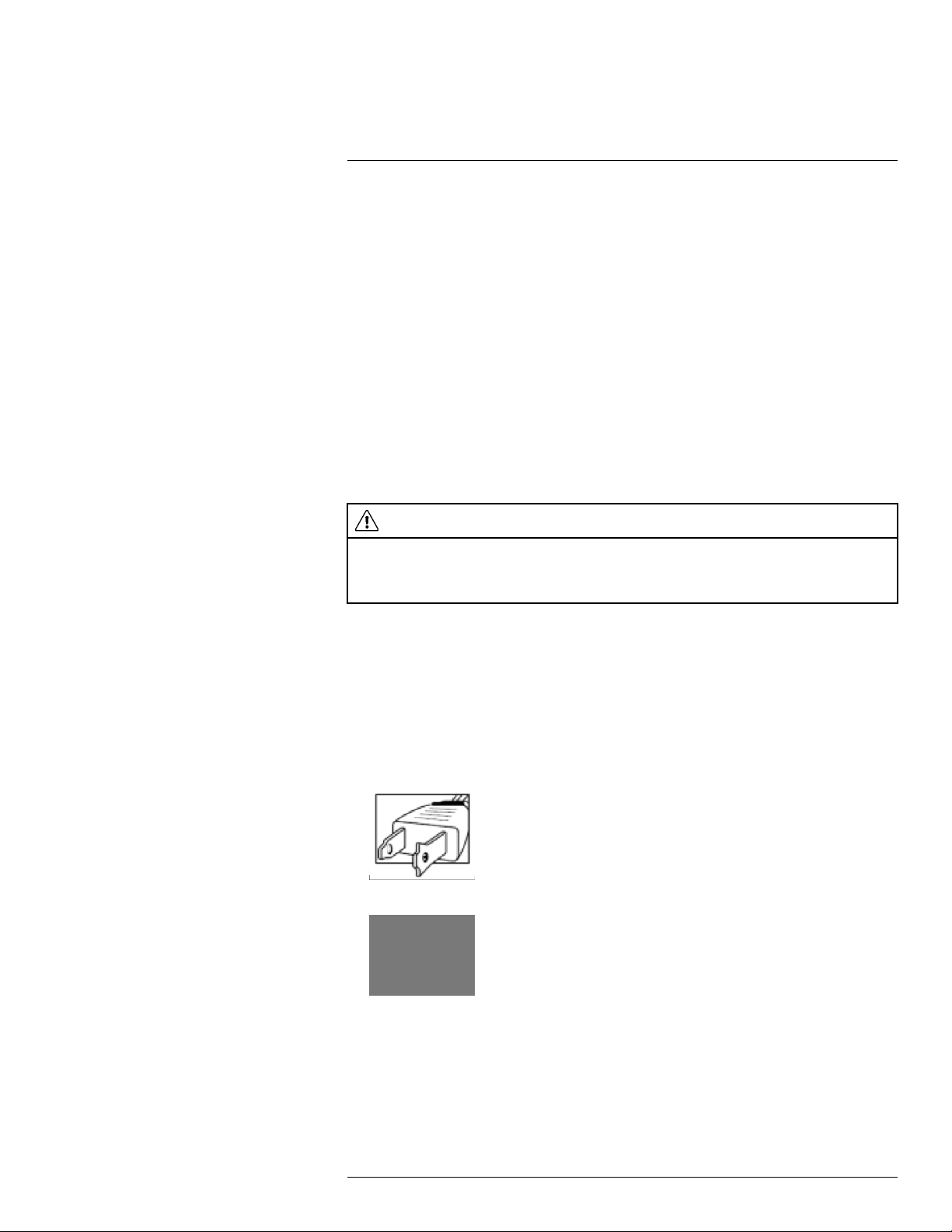
CAUTION: TO PREVENT ELECTRIC SHOCK, MATCH WIDE BLADE OF THE PLUG
TO THE WIDE SLOT AND FULLY INSERT.
#LX400086; r. 1.0/39246/39246; en-US
iv
1
Important Safeguards
In addition to the careful attention devoted to quality standards in the manufacturing process of your product, safety is a major factor in the design of every instrument. However,
safety is your responsibility too. This sheet lists important information that will help to ensure your enjoyment and proper use of the product and accessory equipment. Please read
them carefully before operating and using your product.
1.1 General Precautions
1. All warnings and instructions in this manual should be followed.
2. Remove the plug from the outlet before cleaning. Do not use liquid aerosol detergents.
Use a water-dampened cloth for cleaning.
3. Do not use this product in humid or wet places.
4. Keep enough space around the product for ventilation. Slots and openings in the storage cabinet should not be blocked.
5. It is highly recommended to connect the product to a surge protector to protect from
damage caused by electrical surges. It is also recommended to connect the product to
an uninterruptible power supply (UPS), which has an internal battery that will keep the
product running in the event of a power outage.
CAUTION
Maintain electrical safety. Power line operated equipment or accessories connected to this product
should bear the UL listing mark or CSA certification mark on the accessory itself and should not be modified so as to defeat the safety features. This will help avoid any potential hazard from electrical shock or
fire. If in doubt, contact qualified service personnel.
1.2 Installation
1. Read and Follow Instructions: All the safety and operating instructions should be
read before the product is operated. Follow all operating instructions.
2. Retain Instructions: The safety and operating instructions should be retained for future reference.
3. Heed Warnings: Comply with all warnings on the product and in the operating
instructions.
4. Polarization: Do not defeat the safety purpose of the polarized or grounding-type plug.
A polarized plug has two blades with one wider than the other.
A grounding type plug has two blades and a third grounding prong.
The wide blade or the third prong are provided for your safety.
If the provided plug does not fit into your outlet, consult an electrician for replacement
of the obsolete outlet.
#LX400086; r. 1.0/39246/39246; en-US
1

1
Important Safeguards
5. Power Sources: This product should be operated only from the type of power source
indicated on the marking label. If you are not sure of the type of power supplied to your
location, consult your video dealer or local power company. For products intended to
operate from battery power, or other sources, refer to the operating instructions.
6. Overloading: Do not overload wall outlets or extension cords as this can result in the
risk of fire or electric shock. Overloaded AC outlets, extension cords, frayed power
cords, damaged or cracked wire insulation, and broken plugs are dangerous. They
may result in a shock or fire hazard. Periodically examine the cord, and if its appearance indicates damage or deteriorated insulation, have it replaced by your service
technician.
7. Power-Cord Protection: Power supply cords should be routed so that they are not
likely to be walked on or pinched by items placed upon or against them. Pay particular
attention to cords at plugs, convenience receptacles, and the point where they exit
from the product.
8. Surge Protectors: It is highly recommended that the product be connected to a surge
protector. Doing so will protect the product from damage caused by power surges.
Surge protectors should bear the UL listing mark or CSA certification mark.
9. Uninterruptible Power Supplies (UPS): Because this product is designed for continuous, 24/7 operation, it is recommended that you connect the product to an uninterruptible power supply. An uninterruptible power supply has an internal battery that will
keep the product running in the event of a power outage. Uninterruptible power supplies should bear the UL listing mark or CSA certification mark.
10. Ventilation: Slots and openings in the case are provided for ventilation to ensure reliable operation of the product and to protect it from overheating. These openings must
not be blocked or covered. The openings should never be blocked by placing the product on a bed, sofa, rug, or other similar surface. This product should never be placed
near or over a radiator or heat register. This product should not be placed in a built-in
installation such as a bookcase or rack unless proper ventilation is provided and the
product manufacturer’s instructions have been followed.
11. Attachments: Do not use attachments unless recommended by the product manufacturer as they may cause a hazard.
12. Water and Moisture: Do not use this product near water — for example, near a bath
tub, wash bowl, kitchen sink or laundry tub, in a wet basement, near a swimming pool
and the like.
13. Heat: The product should be situated away from heat sources such as radiators, heat
registers, stoves, or other products (including amplifiers) that produce heat.
14. Accessories: Do not place this product on an unstable cart, stand, tripod, or table.
The product may fall, causing serious damage to the product. Use this product only
with a cart, stand, tripod, bracket, or table recommended by the manufacturer or sold
with the product. Any mounting of the product should follow the manufacturer’s instructions and use a mounting accessory recommended by the manufacturer.
15. Camera Extension Cables: Check the rating of your extension cable(s) to verify compliance with your local authority regulations prior to installation.
16. Mounting:The cameras provided with this system should be mounted only as instructed in this guide or the instructions that came with your cameras, using the provided mounting brackets.
#LX400086; r. 1.0/39246/39246; en-US
2

1
Important Safeguards
17. Camera Installation: Cameras are not intended for submersion in water. Not all cameras can be installed outdoors. Check your camera environmental rating to confirm if
they can be installed outdoors. When installing cameras outdoors, installation in a
sheltered area is required.
1.3 Service
1. Servicing: Do not attempt to service this product yourself, as opening or removing
covers may expose you to dangerous voltage or other hazards. Refer all servicing to
qualified service personnel.
2. Conditions Requiring Service: Unplug this product from the wall outlet and refer
servicing to qualified service personnel under the following conditions:
• When the power supply cord or plug is damaged.
• If liquid has been spilled or objects have fallen into the product.
• If the product has been exposed to rain or water.
• If the product has been dropped or the cabinet has been damaged
• If the product does not operate normally by following the operating instructions. Ad-
just only those controls that are covered by the operating instructions. Improper adjustment of other controls may result in damage and will often require extensive
work by a qualified technician to restore the product to its normal operation.
• When the product exhibits a distinct change in performance. This indicates a need
for service.
3. Replacement Parts: When replacement parts are required, have the service technician verify that the replacements used have the same safety characteristics as the original parts. Use of replacements specified by the product manufacturer can prevent fire,
electric shock, or other hazards.
4. Safety Check: Upon completion of any service or repairs to this product, ask the service technician to perform safety checks recommended by the manufacturer to determine that the product is in safe operating condition.
1.4 Use
1. Cleaning: Unplug the product from the wall outlet before cleaning. Do not use liquid
cleaners or aerosol cleaners. Use a damp cloth for cleaning.
2. Product and Cart Combination: When product is installed on a cart, product and cart
combination should be moved with care. Quick stops, excessive force, and uneven
surfaces may cause the product and cart combination to overturn.
3. Object and Liquid Entry: Never push objects of any kind into this product through
openings as they may touch dangerous voltage points or “short-out” parts that could
result in a fire or electric shock. Never spill liquid of any kind on the product.
4. Lightning: For added protection of this product during a lightning storm, or when it is
left unattended and unused for long periods of time, unplug it from the wall outlet and
disconnect the antenna or cable system. This will prevent damage to the product due
to lightning and power line surges.
#LX400086; r. 1.0/39246/39246; en-US
3

2
Package Contents
Your security DVR package includes the following components:
DVR (Digital Video Recorder)
USB Mouse Ethernet Cable HDMI Cable
12V DC Power Supply
Hard drive size, number of channels, and camera configuration may vary by model. Please
refer to your package for specific details. Check your package to confirm that you have received the complete system, including all components shown above.
Remote Control
(may not be exactly as shown)
Quick Start Guides
#LX400086; r. 1.0/39246/39246; en-US
4

3
DVR Overview
3.1 Front Panel
1. USB Port: Connect a USB mouse (included) or connect a USB flash drive (not included) for data backup or firmware upgrades.
2. HDD – LED Indicator: Glows to indicate hard drive is in normal state. Turns off when
there is a hard drive error.
3. PWR – LED Indicator: Glows to indicate the system is on.
3.2 Back Panel
8–channel DVR:
16–channel DVR:
1. Video Input: Connect Lorex by FLIR wired HD cameras. For a full list of compatible
cameras, visit lorextechnology.com/compatibility.
#LX400086; r. 1.0/39246/39246; en-US
5
3
DVR Overview
2. Audio Input: Connect a self-powered microphone (not included) to the Audio Input
ports to record up to 4 channels of audio. To hear and record audio from the cameras,
ensure you have enabled audio for both the mainstream and substream. See 12.2.11
Configuring System Recording Quality (Mainstream and Substream), page 60 for full
instructions.
3. Audio Output: Connect a speaker (not included) to the Audio Output port.
4. HDMI: Connect to an HDMI monitor or TV (not included – 4K output supported) to view
the system interface.
5. LAN: Connect a CAT5 RJ45 Ethernet cable for local and remote connectivity.
6. USB Port: Connect a USB mouse (included) or connect a USB flash drive (not included) for data backup or firmware upgrades.
7. Power (12V): Connect the included 12V DC power adapter.
8. RS485: Connect RS485 cables.
NOTE
• For full instructions on connecting PTZ cameras using RS485 cables, see 17 Connecting PTZ
Cameras to the DVR, page 138.
• Once you have connected the PTZ camera to the DVR, you will need to enter the PTZ camera’s
information so it can receive commands from the DVR. See 12.4.3 Configuring PTZ Cameras,
page 75 for details.
9. VGA: Connect a VGA monitor (not included) to view the system interface.
#LX400086; r. 1.0/39246/39246; en-US
6

4
Basic Setup
4.1 STEP 1: Connect the BNC cameras
Connect BNC cameras to the Video Input ports on the rear panel of the DVR. Push and
twist the BNC connector clockwise to secure it to the BNC port.
4.2 STEP 2: Connect the mouse
Connect the included USB mouse to one of the USB ports.
4.3 STEP 3: Connect the Ethernet cable
Connect the included Ethernet cable to the LAN port on the rear panel of the DVR. Connect the other end of the Ethernet cable to a router on your network.
4.4 STEP 4: Connect the monitor or TV
Connect the included HDMI cable from the HDMI port to the TV or monitor
(recommended).
OR
Connect a VGA cable (not included) from the VGA port to the monitor.
#LX400086; r. 1.0/39246/39246; en-US
7
4
Basic Setup
1. VGA cable (not included) — supports up to 1080p output.
2. HDMI cable (included)
• 4–channel DVRs: Supports up to 1080p output.
• 8/16–channel DVRs: Supports up to 4K output (4K monitor/TV required).
4.5 STEP 5: Connect the power adapter
Connect the included power adapter to the 12V port. Connect the end of the power adapter to a wall socket or a surge protector. The DVR will power on.
NOTE
At startup, the system performs a basic system check and runs an initial loading sequence. After a few
moments, the system loads a live display view.
4.6 STEP 6: Upgrade firmware to latest version (if available)
If a firmware upgrade is available, you will be asked to install it once the DVR starts up. It is
required to upgrade your system firmware and client software / mobile apps to the latest
version to enable remote connection to the system.
If a firmware upgrade is available:
1. After startup, a notification will appear asking you to upgrade the firmware. Click OK to
upgrade.
#LX400086; r. 1.0/39246/39246; en-US
8
4
Basic Setup
2. Enter the system user name (default: admin) and password (default: 00000000) and
click OK. Wait for the firmware update to complete. The system will restart once the
firmware has been upgraded.
CAUTION
DO NOT POWER OFF THE DVR OR DISCONNECT THE POWER CABLE DURING FIRMWARE
INSTALLATION
4.7 STEP 7: Create a secure password
The first time you power up your system, you will be asked to create a new, secure password that is 8–15 characters long.
1. Enter the system user name (default: admin) and password (default: 00000000)
2. You will be asked to create a new, secure 8–15 character password. Enter your new
password in the New Password and Confirm Password fields, then press OK to
confirm.
NOTE
Your new password will be used to access the system from now on.
4.8 STEP 8: Complete the Setup Wizard
After setting a secure password, the DVR Setup Wizard launches. The wizard has you set
your language, region, and confirm the correct date and time for the system.
1. The setup wizard launches. Click Next to begin.
#LX400086; r. 1.0/39246/39246; en-US
9

4
Basic Setup
2. Click the arrow keys to select your preferred language for the on-screen display. Click
Next to confirm.
3. Click the arrow keys to select your correct region. Click Next to confirm.
4. Configure all fields related to date and time:
4.1. Click to select the correct date from the calendar.
4.2. Click to enter the correct time.
4.3. Select your preferred date format from the dropdown. This determines how the
date will appear in date stamps.
4.4. Select your preferred time format from the dropdown. This determines how the
time will appear in time stamps. If you select 12Hour format, select AM or PM.
4.5. Click Next.
#LX400086; r. 1.0/39246/39246; en-US
10
4
Basic Setup
5. Review the information on the final screen of the wizard. Click Accept to confirm that
all information is correct, or click Previous to go back to a previous screen in the
wizard.
Once you have completed the wizard, the date and time of the system is updated. You
can make changes at any time to the date, time or region. See 12.5.1 Changing the
Date and Time, page 76 for details.
4.9 STEP 9: Verify camera image
• Power on the cameras, and then verify the camera video quality before mounting the
cameras to a permanent location.
• Mount the cameras under a sheltered location. Always verify the outdoor rating of your
camera before installing it in a permanent location.
CAUTION
Cameras differ in terms of installation or mounting instructions. Please see the documentation that came
with your camera(s) for specific installation instructions.
4.9.1 Camera Installation Tips
• Mount the camera where the lens is away from direct and intense sunlight.
• Plan your cable wiring so that it does not interfere with power lines or telephone lines.
• Ensure that the camera wiring is not exposed or easily cut.
• Mount the camera in an area that is visible, but out of reach.
• Avoid pointing the camera at a glass window to see outside, as this may result in a poor
image caused by glare from indoor / outdoor lighting conditions.
• Adjust the camera angle so that it covers an area with high traffic.
• In "high-risk" locations, have multiple cameras point in the same area. This provides
camera redundancy if a vandal attempts to damage the camera.
4.10 Connecting to Your DVR Over the Internet
The system features FLIR Cloud Services. This is a cloud service that allows you to connect with your system over the Internet via a secure handshake with FLIR servers. This
means you can easily connect to your system without requiring any port forwarding or other network configuration.
• For details on connecting to your using a smartphone or tablet, see 14 FLIR Secure:
Connecting to the DVR Using a Mobile Device, page 124.
• For details on connecting to your using a PC or Mac computer, see 13 FLIR Client 12
for PC / Mac, page 91.
4.11 Quick Access to System Information
To quickly open a window with system information:
#LX400086; r. 1.0/39246/39246; en-US
11

4
Basic Setup
• Click
OR
• Press the
on the DVR’s Taskbar.
button on the included remote control.
#LX400086; r. 1.0/39246/39246; en-US
12

5
Using the Mouse
The DVR is designed for mouse navigation. Connect the included mouse to one of the
USB ports on the DVR.
To use the USB mouse:
1. Left Button:
• Click to select menu options.
• During live viewing in split-screen view, double-click on a channel to view it in full-
screen. Double-click the channel again to return to split-screen viewing.
2. Right Button:
• During live viewing in split-screen view, click to open the Quick Menu (see 7.2 Using
the Quick Menu, page 16).
• In menus, click to go back / close menus.
3. Scroll Wheel:
• In menus, scroll to move up / down through the menu content.
• While hovering over the volume control wheel, scroll to turn system volume up /
down.
#LX400086; r. 1.0/39246/39246; en-US
13

6
Using the Remote Control
You have the option of controlling your security system using the included remote control
instead of the included mouse, which is intended as the primary way of controlling the system (for details, see 5 Using the Mouse, page 13).
To use the remote control:
1. Number Keys (1~0): Press to select the desired channel in Full-screen View.
•
• MENU/ESC: Press to open the Main Menu. In menus, press to go back / exit
• 0: Press 0 three times set the DVR’s video output to the default resolution of
2. Navigation Cursors: Press to navigate menus.
•
3. Sub Menu: Press to open the Menu Bar.
4. ID: Used to pair the remote control to a specific DVR. For details, see 12.5.11 Setting
the Remote ID, page 85.
5. MUTE: Press to mute/un-mute audio during Live Viewing and Playback Mode. Audiocapable cameras (not included) are required for audio recording and listen-in audio
functionality.
: In Live Viewing Mode, press to open Split-screen View. Press repeatedly to
switch between split-screen viewing modes.
menus.
1280×1024.
: Press to select menu items. In Live Viewing Mode, press to access System
Information.
#LX400086; r. 1.0/39246/39246; en-US
14

6
Using the Remote Control
6. Playback Controls:
•
: In Playback Mode, press to fast forward/increase fast forward speed.
: In Playback Mode, press to rewind/increase rewind speed.
•
: In Live Viewing Mode, press to open the Search Menu to select video for
•
playback.
In Playback Mode, press to play video.
•
: In Live Viewing Mode, press to start Sequence Mode.
In Playback Mode, press to pause video. Press repeatedly to step through video
frames.
•
: Press to stop recording. Password required; does not override scheduled
recording.
•
: Press to resume recording after recording has been stopped. Password
required.
#LX400086; r. 1.0/39246/39246; en-US
15
7
Using the DVR’s On-Screen Display
Use the system’s graphical on-screen display to navigate menus and configure options
and settings.
7.1 Using the Taskbar
The Taskbar along the bottom of the DVR’s main display allows you to access the Main
Menu and control basic functions of the DVR.
1. Main Menu: Opens the Main Menu for browsing. For details on Main Menu functions,
see 12 Using the Main Menu, page 48.
2. View Options: Select how many camera channels are shown during live viewing.
3. Start / Stop SEQ: Start or stop Sequence Mode. In Sequence Mode, the DVR automatically switches between channels every few seconds.
4. Playback: Opens the Playback Menu. This allows you to search for video recordings
saved on the DVR’s hard drive. For details on using the Playback menu, see 9 Play-
back, page 25.
5. Mute: Mute system audio.
NOTE
Muting system audio does not affect audio in recordings (microphone required — see 18 Recording
Audio, page 139 for details).
6. Volume Bar: Click inside the Volume Bar, or hover over it and use the scroll wheel to
change system volume.
7. System Information: Displays system information.
8. Auto Upgrade: Checks for an available firmware update. For details, see 12.6.6 Using
Automatic Firmware Upgrade, page 90
9. System Date & Time: Shows the date and time of the system.
10. Pin / Unpin Taskbar: Choose to always show the Taskbar on screen (
unless the mouse pointer is near the bottom of the screen (
7.2 Using the Quick Menu
The Quick Menu gives you quick access to functions which can also be accessed using
the Taskbar.
To use the Quick Menu:
• Right-click on a camera channel in the live viewing screen.
• The Quick Menu appears:
).
) or hide it
#LX400086; r. 1.0/39246/39246; en-US
16

7
Using the DVR’s On-Screen Display
1. Main Menu: Open the Main Menu. For details on Main Menu functions, see 12 Using the Main Menu, page 48.
2. Multi View: Select how many channels appear on the live display at once.
3. Last Screen: View the previous channel or page of channels.
4. Next Screen: View the next channel or page of channels.
5. Start SEQ / Stop SEQ: Start or stop Sequence Mode, which cycles through connected cameras automatically.
6. Playback: Search for and play back recorded video. For details on using Playback,
see 9 Playback, page 25.
7. PTZ: Control PTZ cameras. For details, see 7.5 Using PTZ Controls, page 20.
7.3 Using the Mini Menu
The Mini Menu lets you perform quick functions for a specific channel on the DVR.
To use the Mini Menu:
• Hover the mouse near the top of a channel with a connected camera.
• The Mini Menu opens at the top of the camera’s live display:
#LX400086; r. 1.0/39246/39246; en-US
17

7
Using the DVR’s On-Screen Display
1. Move Mini Menu: Click-and-drag to move the Mini Menu to a different part of the
screen.
2. Manual Capture: Click to save a snapshot of the current camera image. Manual Capture must be enabled to use this feature. For details on enabling Manual Capture, see
12.2.14 Enabling Manual Capture, page 63.
3. Manual Recording: Click to manually record video from the selected channel. Password entry required.
4. Instant Playback: Plays back up to 5 minutes of the most recently recorded video
from the selected channel.
5. Digital Zoom: Click, then click-and-drag on an area of the camera image to view it in
greater detail. For full instructions, see 7.6 Using Digital Zoom, page 22.
6. Color Adjustments: Adjust the hue, brightness, contrast and saturation of the camera
image. For details, see 12.2.2 Adjusting Camera Image Color, page 51.
7. PTZ Controls: Click to open PTZ controls. Password entry required. For more details
on using PTZ controls, see 7.5 Using PTZ Controls, page 20.
7.4 Using the On-Screen Keypads
The Full Keypad is used to input alphanumeric characters, such as in user name or password fields. The Number Keypad is used to input numeric characters only, such as in the
time or date fields.
To use the Full Keypad:
#LX400086; r. 1.0/39246/39246; en-US
18
7
Using the DVR’s On-Screen Display
1. Using the mouse, click on a field where alphanumeric characters are entered, such as
the user name and password fields.
• The Full Keypad opens:
• Click to switch between uppercase and lowercase characters.
NOTE
Uppercase entry mode also reveals more special characters on the far-right side of the keyboard.
• Click / to move the cursor.
• Click
• Click
to backspace / delete characters.
to confirm what you have entered.
• Right-click to close the Full Keypad.
To use the Number Keypad:
#LX400086; r. 1.0/39246/39246; en-US
19
7
Using the DVR’s On-Screen Display
1. Using the mouse, click on a field where numeric characters are entered, such as the
date or time fields.
• The Number Keypad opens:
• Click / to move the cursor between letters.
• Click
• Click
to backspace / delete numbers.
to confirm what you have entered.
• Right-click to close the Number Keypad.
NOTE
You may also enter numerical information using the included remote control. See 6 Using the Remote
Control, page 14 for details.
7.5 Using PTZ Controls
Controlling Pan-Tilt-Zoom (PTZ) cameras (PTZ cameras sold separately).
NOTE
Ensure you have completed initial setup of your PTZ camera in order to control the camera using the
DVR. See 12.4.3 Configuring PTZ Cameras, page 75 for more details.
To access the PTZ controls:
• Right-click on the live viewing area for the PTZ camera to open the Quick Menu, then
click PTZ.
OR
• Hover the mouse near the top of the live viewing area for the PTZ camera to reveal the
Mini Menu, then click
.
To use the PTZ controls:
#LX400086; r. 1.0/39246/39246; en-US
20
7
Using the DVR’s On-Screen Display
1. Channel: Select the channel of the PTZ camera you want to control.
2. Navigation Controls: Click the directional arrows to move the PTZ camera.
3. Start Cruise: Cycles between preset viewing points automatically.
NOTE
PTZ cruise must be enabled on the DVR. See 12.4.3 Configuring PTZ Cameras, page 75 for details.
4. OSD Menu: On supporting cameras, access advanced camera settings in the OnScreen Display (OSD) menu.
NOTE
You can reset OSD menu settings on supporting cameras by performing a default settings reset on
the DVR. See 12.6.2 Restoring Default Settings, page 86 for details.
5. Close PTZ Controls
6. Speed: Set the speed of the PTZ camera’s movement.
7. Zoom: Click –/+ to zoom in or out.
8. Focus: Click –/+ to adjust the focus.
9. Iris: Click –/+ to set the iris.
10. Preset: Click to access preset settings. For details on setting presets, see 7.5.1 Set-
ting PTZ Presets, page 21
7.5.1 Setting PTZ Presets
Access the PTZ control menu to set preset viewing points for the PTZ. This is helpful for
saving frequently-monitored areas for quick viewing. Once you have saved a few preset
viewing points, you can start a PTZ cruise to switch between preset points automatically
by clicking
.
To set PTZ presets:
#LX400086; r. 1.0/39246/39246; en-US
21
7
Using the DVR’s On-Screen Display
1. Select the channel for the PTZ camera you want to set presets for.
2. Use the directional arrows to move the PTZ camera to the desired view for the preset.
3. Click the arrow next to PRESET to reveal preset controls.
4. In the field next to No., enter an ID number for the current preset viewing point.
NOTE
You must enter a unique ID number for each preset viewing area you add to the system. Using the
same ID number as an existing preset will result in the old preset being overwritten.
5. In the field next to Time, enter an amount of time in seconds. This will determine how
long the PTZ camera looks at the preset area before switching to the next preset in a
cruise.
6. Click + to confirm your preset settings and add it to the system.
7. Configure as many preset points as needed using the steps above, then click Save.
NOTE
To cycle through preset viewing points automatically, click
enabled cruise on the selected PTZ camera (see 12.4.3 Configuring PTZ Cameras, page 75 for
details).
to start PTZ Cruise. Ensure you have
7.6 Using Digital Zoom
Zoom in on an area of live video to enlarge a part of the image.
NOTE
Digital zoom is not the same as optical zoom, which is supported only by PTZ and motorized lens cameras. For details on using optical zoom on supporting cameras, see 7.5 Using PTZ Controls, page 20.
To use digital zoom:
1. During live view, hover near the top of the channel to reveal the Mini Menu.
#LX400086; r. 1.0/39246/39246; en-US
22

7
Using the DVR’s On-Screen Display
2. Click
.
3. Click-and-drag on the video image to select an area to enlarge.
The enlarged image is shown in full screen. A Picture-in-Picture view in the bottomright corner shows the full image with the zoom area highlighted.
4. Right-click to return to live viewing.
#LX400086; r. 1.0/39246/39246; en-US
23

8
Recording
By default, the system is set to immediately record video from all connected cameras in
both continuous recording and motion recording modes.
When a camera is recording video, the type of recording is indicated by icons in the bottom-left corner of the camera image.
You may see one of the following icons:
•
Continuous Recording: The system is recording video constantly. By default, the
system is set to record continuously at all times. You can make a schedule to set when
the system records continuous video. See 12.2.10 Setting the Recording Schedule,
page 59 for details.
•
Motion Recording: The system has detected motion and is recording the event.
◦ By default, the system is set to record motion events at all times. You can make a
schedule to set when the system records motion detection. See 12.2.10 Setting the
Recording Schedule, page 59 for details.
◦ To configure more motion detection options such as detection sensitivity, active
areas for motion detection, and warning/buzzer options, see 12.2.20 Configuring
Motion Detection Settings, page 71.
•
Motion Detected — No Recording: The system detected motion, but motion recording is not enabled or a recording schedule has been set to disable motion recording during this time of day.
◦ To enable motion detection on the selected channel, see 12.2.20 Configuring Motion
Detection Settings, page 71.
◦ To edit the recording schedule for the selected channel, see 12.2.10 Setting the Re-
cording Schedule, page 59.
#LX400086; r. 1.0/39246/39246; en-US
24
9
Playback
You can view and back up recorded video on the DVR.
To access playback:
• Click
OR
• Right-click during live view to open the Quick Menu, then click Playback.
9.1 Using Playback
Play back video recordings from a specific date and time.
To use video playback:
on the Taskbar
1. Use the calendar to select a day for playback. Dates with available recordings will be
marked with a triangle in the bottom corner (
• Green: Continuous recording available.
• Red: Motion recording available.
2. Select Record from the dropdown next to Playback Type .
NOTE
Selecting other options from the Playback Type dropdown will change the controls for the playback
menu. See below for details on each of the other types of playback:
• Events: Search for video recordings with the option to filter by recording type. See 9.3 Event
Playback Controls, page 27 for details.
• Pictures: Search for snapshots taken using Auto and Manual Capture. See 9.4 Picture Playback
Controls, page 28 for details.
• Smart Search: Smart Search allows you to review events intelligently, with the ability to clearly
see when there was activity in a specific part of the camera image. See 9.5 Smart Search Play-
back Controls, page 29 for details.
3. Check the channels you would like to play back, or check Select to playback all connected cameras.
).
#LX400086; r. 1.0/39246/39246; en-US
25

Playback9
4. Playback of the selected channels begins immediately. The timeline will show green
bars representing continuous recording, and yellow bars representing motion record-
ing. Click on a section of video in the timeline to change playback position.
For a full overview of video playback controls, see 9.2 Video Playback Controls, page
26.
9.2 Video Playback Controls
1. Calendar: Select a date to search for video recordings from.
2. Playback Type: Select Record.
NOTE
This is the default method for searching for video recordings on the system. See below for details on
the other types of playback:
• Events: Search for video recordings with the option to filter by recording type. See 9.3 Event
Playback Controls, page 27 for details.
• Pictures: Search for snapshots taken using Auto and Manual Capture. See 9.4 Picture Playback
Controls, page 28 for details.
• Smart Search: Smart Search allows you to review events intelligently, with the ability to clearly
see when there was activity in a specific part of the camera image. See 9.5 Smart Search Play-
back Controls, page 29 for details.
3. Channel List: Check channels you would like to search, or check Select to search all
connected channels.
4. Full Screen
5. Rewind
6. Slow Play: Click to slow playback by half-speed. Click repeatedly to play as slow as 1/
16 of normal speed.
7. Play
8. Pause
9. Stop
10. Fast-Forward
#LX400086; r. 1.0/39246/39246; en-US
26
 Loading...