


Web Managed GbE Switch
1
8-Port Gigabit Ethernet Web
Managed Switch
LCS-GS8408
User Manual

Web Managed GbE Switch
2
FCC Certifications
This Equipment has been tested and found to comply with the limits for a Class B digital device,
pursuant to part 15 of the FCC Rules. These limits are designed to provide reasonable protection
against harmful interference when the equipment is operated in a commercial environment. This
equipment generates, uses, and can radiate radio frequency energy and, if not installed and used
in accordance with the instruction manual, may cause harmful interference to radio
communications.
Operation of this equipment in a residential area is likely to cause harmful interference in which
case the user will be required to correct the interference at his own expense.
This device complies with Part 15 of the FCC Rules. Operation is subject to the following two
conditions: (1) this device may not cause harmful interference, and (2) this device must accept any
interference received; including interference that may cause undesired operation.
CE Mark Warning
This equipment complies with the requirements relating to the EMC Directive 2004/108/EC, the
Low Voltage Directive 2006/95/EC, and the RoHS Directive 2011/65/EU.
Company has an on-going policy of upgrading its products and it may be possible that information
in this document is not up-to-date. Please check with your local distributors for the latest
information. No part of this document can be copied or reproduced in any form without written
consent from the company.
Trademarks:
All trade names and trademarks are the properties of their respective companies.
Copyright © 2014, All Rights Reserved.

Web Managed GbE Switch
3
Table of Contents
Chapter 1 Introduction to the Web Smart Switch ············································ 5
1.1 General Description ················································································ 5
1.2 The Front Panel ····················································································· 6
1.3 LEDs Definition ······················································································ 6
1.4 The Rear Panel ······················································································ 6
1.5 Installation ····························································································· 8
Chapter 2 Basic Web Management Information ············································ 10
2.1 System login ························································································· 10
2.2 The Graphic User Interface ······································································ 10
2.3 SAVE LOGOUT REBOOT ······································································· 15
2.3.1 SAVE ································································································ 15
2.3.1.1Saving running configurations ······························································ 15
2.3.2 LOGOUT ··························································································· 15
2.3.3 REBOOT ··························································································· 16
Chapter 3 Web Management Configuration ·················································· 17
3.1 Status·································································································· 17
3.1.1 System Information ············································································· 17
3.1.2 Logging Message ················································································ 17
3.1.3 Port ·································································································· 18
3.1.4 Link Aggregation ················································································· 20
3.1.5 LLCP Statistics ··················································································· 21
3.1.6 IGMP Snooping Statistics ····································································· 23
3.2 Network ······························································································· 24
3.2.1 IP Address ························································································· 24
3.2.2 IPv6 Address ······················································································ 25
3.2.3 Management VLAN ············································································· 26
3.2.4 Time Settings ····················································································· 26
3.2.5 SNTP Settings ···················································································· 28
3.3 Switching ····························································································· 28
3.3.1 Port Setting ························································································ 28
3.3.2 Port Mirroring ····················································································· 30
3.3.3 Link Aggregation ················································································· 31
3.3.4 VLAN Management ············································································· 36
3.3.5 EEE·································································································· 42
3.3.6 Multicast ···························································································· 43
3.3.7 Jumbo Frame ····················································································· 50
3.3.8 STP ·································································································· 51

Web Managed GbE Switch
4
3.4 MAC Address Table················································································ 56
3.5 Security ······························································································· 59
3.5.1 Storm Control ····················································································· 59
3.5.2 Protected Ports ··················································································· 60
3.5.3 DoS ·································································································· 61
3.5.4 Access ······························································································ 64
3.6 QoS ···································································································· 66
3.6.1 General ····························································································· 67
3.6.2 QoS Basic Mode ················································································· 72
3.6.3 Rate Limit ·························································································· 74
3.7 Management ························································································ 77
3.7.1 LLDP ································································································ 77
3.7.2 SNMP ······························································································· 84
3.8 Diagnostics ·························································································· 87
3.8.1 Cable Diagnostics ··············································································· 87
3.8.2 Ping Test ··························································································· 87
3.8.3 IPv6 Ping Test ···················································································· 88
3.8.4 Logging Setting··················································································· 89
3.8.5 Factory Default ··················································································· 91
3.8.6 Reboot Switch ···················································································· 92
3.9 Maintenance ························································································· 92
3.9.1 Backup Manager ················································································· 92
3.9.2 Upgrade Manager ··············································································· 93
3.9.3 Configuration Manager ········································································· 94
3.9.4 Account Manager ················································································ 95
Product Specifications ················································································· 97

Web Managed GbE Switch
Chapter 1 Introduction to the Web Smart Switch
1.1 General Description
High Performance
The device is a powerful, high-performance Gigabit Ethernet switch with 8 10/100/1000 Mbps ports,
providing you a cost-effective, space-saving solution for expanding your network. The gigabit ports
can lead you to a real gigabit connection, making you be able to transfer high bandwidth-needed
files higher and faster in an easy way.
This device provides the easy management function through the Ethernet Web. The network
administrator can configure the status and the port function setting of the device through the
Web-Based UI. When installing the auto-discovery management tool helps network managers to
search and access those switches on LAN easily. Therefore, network managers can access
switches that support auto-discovery on LAN without memorizing IP address.
Smart Features
The device provides rich features including Link Aggregation, VLANs, IGMP Snooping, Port
Trunking, Spanning Tree, Security and other network management to meet the requirements
evolving medium and small-sized enterprises. QoS secures the bandwidth for some
bandwidth-demanded applications including VoIP or video conference. Additionally, IEEE 802.3az
Energy Efficient Ethernet ability is supported to promise operation in Low Power Idle Mode and
save power consumption.
Easy Installation and Management
This switch is plug & play and hassle-free in installation. Auto-MDI/MDI-X crossover on all ports
eliminates the need for crossover cables for connection to another switch or hub. Auto-Negotiation
on each port senses the link speed of a network device and intelligently adjusts for compatibility and
optimal performance. This switch also features diagnostic LEDs, which display the status and
activities of the network.
5
Web Managed GbE Switch
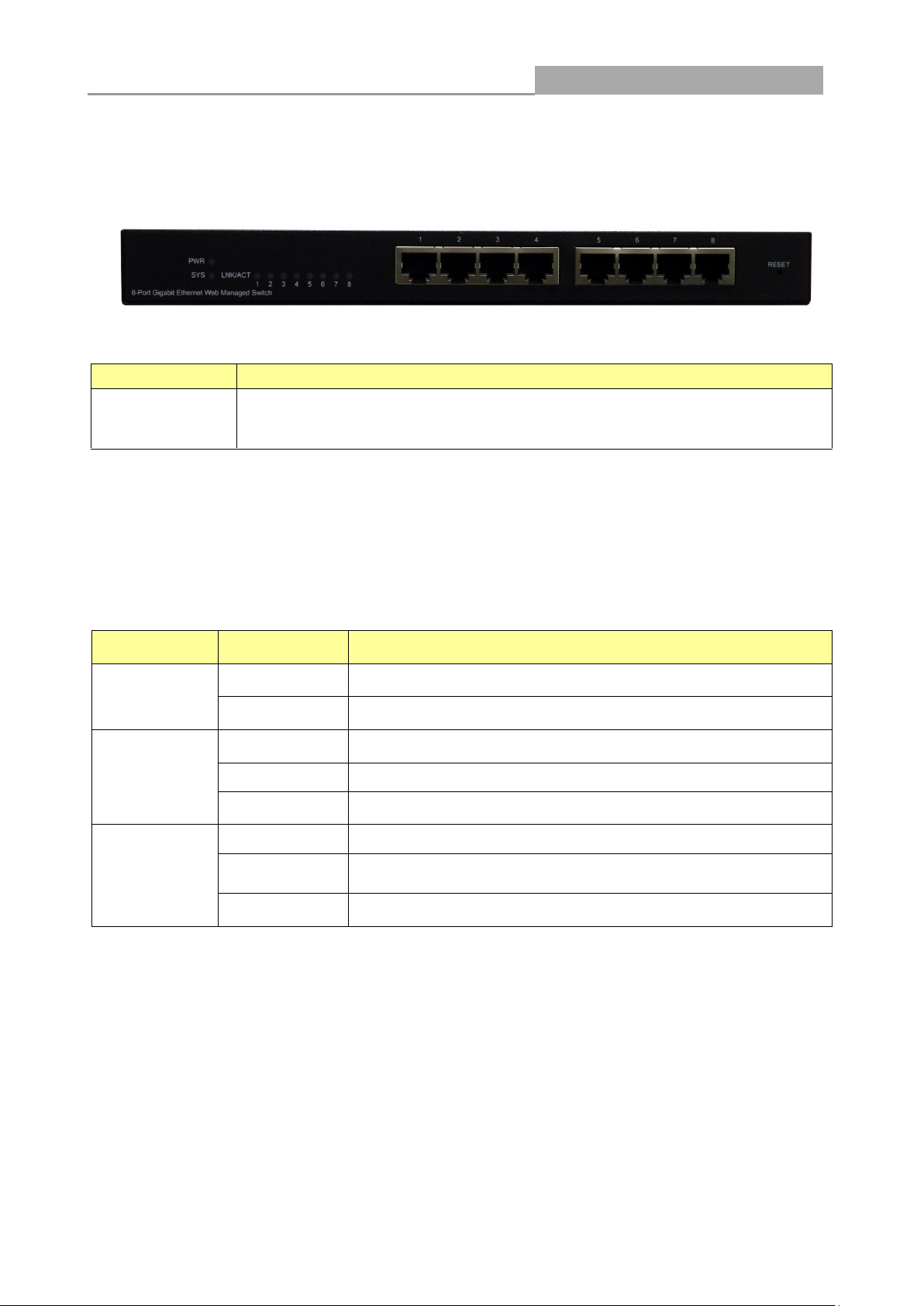
LABEL
DESCRIPTON
8 10/100/1000
RJ-45 Ethernet
Ports
Connect these ports to a computer, a hub, an Ethernet switch or router
LED
Status
Operation
PWR
Steady Green
The switch is powered on.
Off
The switch is powered off.
SYS
Steady Green
The switch is on and functioning properly.
Blinking Green
The switch is rebooting and performing self-diagnostic tests.
Off
The power is off or the system is not ready/malfunctioning.
Link/ACT
Steady Green
The link to a 1000 Mbps Ethernet network is up.
Blinking Green
The system is transmitting/receiving to/from a 1000 Mbps
Ethernet network.
Off
Port disconnected.
1.2 The Front Panel
The following figure shows the front panel of the switch.
The following table describes the port labels on the front panel.
1.3 LEDs Definition
This device provides extensive LEDs to show the activities on power, system and ports.
See the following description for your reference:
The RESET Button
Reset the switch to its factory default configuration via the RESET button. Press the RESET button
for three seconds and release. The switch automatically reboots and reloads its factory
configuration file. The RESET button is on the front panel of the switch.
1.4 The Rear Panel
The following figure shows the rear panel of the switch:
6

Web Managed GbE Switch
7
Power Receptacle
To be compatible with the electric service standards around the world, the switch is designed to
afford the power supply in the range from 100 to 240 VAC, 50/60 Hz. Please make sure that your
outlet standard to be within this range.
To power on the switch, please plug the female end of the power cord firmly into the receptacle of
the switch, the other end into an electric service outlet, and use the POWER ON/OFF switch to have
the Switch power on or off. After the switch powered on, please check if the power LED is lit for a
normal power status.

Web Managed GbE Switch
1.5 Installation
This switch can be placed on your desktop directly, or mounted on the wall. Please refer to the
instructions for installation.
Before installing the switch, we recommend:
1. The switch is placed with appropriate ventilation environment. A minimum 25 mm space around
the unit is recommended.
2. The switch and the relevant components are away from sources of electrical noise such as
radios, transmitters and broadband amplifiers
3. The switch is away from environments beyond recommend moisture
Desktop Installation
1. Install the switch on a level surface that can support the weight of the unit and the relevant
components.
2. Plug the switch with the power cable of adaptor and plug the power adaptor to the power outlet.
Wall-mount Installation
The switch may be standalone, or mounted on wall. Wall mounting facilitate to an orderly
installation when you are going to install series of networking devices.
Procedures to Wall-mount the switch:
1. Screw the two screws provided with your Switch into the wall. Use screws with 6 mm ~ 8 mm (0.24" ~
0.31") wide heads. Do not screw the screws all the way in to the wall; leave a small gap between the
head of the screw and the wall.
2. Align the holes on the back of the Switch with the screws on the wall. Hang the Switch on the screws.
Note:
The Switch should be wall-mounted horizontally. The Switch's side panels with ventilation slots
should not be facing up or down as this position is less safe.
Installing Network Cables
1. Crossover or straight-through cable: All the ports on the switch support Auto-MDI/MDI-X
functionality. Both straight-through or crossover cables can be used as the media to connect the
switch with PCs as well as other devices like switches, hubs or router.
8

Web Managed GbE Switch
9
Media
Speed
Wiring
10/100/1000 Mbps
copper
10 Mbps
Category 3,4,5 UTP/STP
100 Mbps
Category 5 UTP/STP
1000 Mbps
Category 5e, 6 UTP/STP
2. Category 3, 4, 5 or 5e, 6 UTP/STP cable: To make a valid connection and obtain the optimal
performance, an appropriate cable that corresponds to different transmitting/receiving speed is
required. To choose a suitable cable, please refer to the following table.
Web Managed GbE Switch
10
Chapter 2 Basic Web Management Information
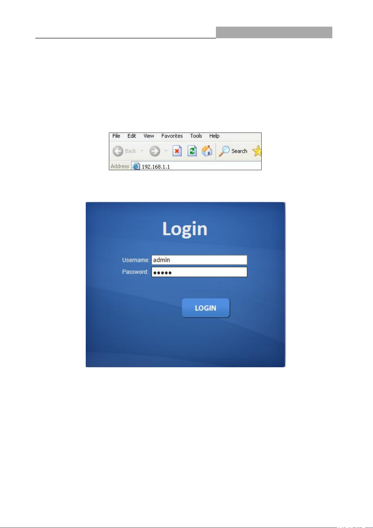
2.1 System login
1. Start your web browser.
2. Type “http://”and the IP address of the switch (for example, the default management IP address
is 192.168.1.1) in the Location or Address field. Press [ENTER].
3. The login screen appears. The default username and password are “admin”, so you can click
OK and go to the web configuration screen directly.
2.2 The Graphic User Interface
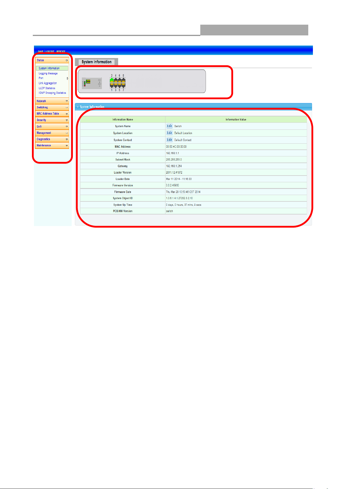
After the password authorization, the information page shows up. You may click on each folder on
the left column of each page to get access to each configuration page. The Graphic User Interface
is as follows:
Web Managed GbE Switch
11
A B C
A –Click the menu items to open submenu links, and then click on a submenu link to open the
screen in the main window.
B –It shows the switch’s current link status. Green squares indicate the port link is up, while black
squares indicate the port link is down.
C –Displays system information such as MAC address and firmware version.
Web Managed GbE Switch
12
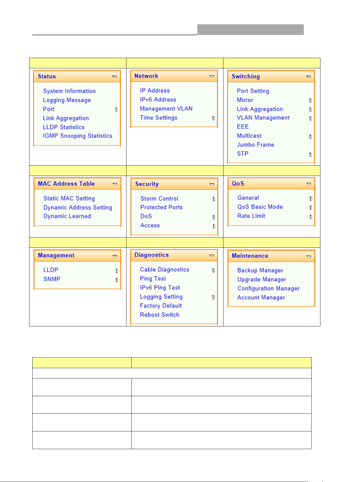
Status
Network
Switching
MAC Address Table
Security
QoS
Management
Diagnostics
Maintenance
LINKS
DESCRIPTION
Status
System Information
This link takes you to a screen that displays general system
information.
Logging Message
This sub-menu takes you to screens where you can view and
setup system logs.
Port
This link takes you to a screen where you can configure the
port information.
Link Aggregation
This link takes you to a screen where you review the LAG
Status and the LACP Information.
In the navigation panel, click a main link to reveal a list of submenu links shown as the following:
The following table describes the links in the navigation panel.

Web Managed GbE Switch
13
LLDP Statistics
This link takes you to view the summary and per-port
information for LLDP frames transmitted and received on the
switch.
IGMP Snooping Statistics
This link takes you to see the statistics information of IGMP.
Network
IP Address
This link takes you to a screen where you can configure the
IP information.
IPv6 Address
This link takes you to a screen where you can configure the
IPv6 information.
Management VLAN
This link takes you to view the entry of a VLAN from which a
management station will be allowed to manage the device
using TCP/IP (in-band via web manager or Telnet).
Time Settings
This link takes you to a screen where you can configure the
switch’s time settings.
Switching
Port Setting
This link takes you to a screen where you can configure
settings for individual switch ports.
Mirror
This sub-menu takes you to screens where you can copy
traffic from one port or ports to another port in order that you
can examine the traffic from the first port without
interference.
Link Aggregation
This link takes you to a screen where you can configure the
trunk settings on a port.
VLAN Management
This link takes you to a screen where you can configure the
VLAN (IEEE 802.1Q) settings on a port.
EEE
This link takes you to enable or disable port EEE(Energy
Efficient Ethernet) function.
Multicast
This link takes you to set multicast filtering and unknown
multicast action.
Jumbo Frame
This link takes you to a screen where you can configure the
Jumbo Frame size.
STP
This sub-menu takes you to screens where you can
configure the STP to prevent network loops.
MAC Address Table
Static MAC Setting
This link takes you to display and configure the Static MAC
settings.
Dynamic Address Setting
This link takes you to configure the Dynamic Address
settings.
Dynamic Learned
This link takes you to a screen where you can to view the
Dynamic Address settings information.
Security
Storm Control
This link takes you to a screen where you can limit the
number of broadcast, multicast and unknown unicast and
multicast packets the Switch receives per second on the
ports.
Protected Ports
This link takes you to a screen to setting and revising the
protected ports.

Web Managed GbE Switch
14
DoS
This link takes you to configure DoS setting to enable/disable
DoS function and all others related in the sub-menu.
Access
This link takes you a way to access the switch.
QoS
General
This link takes you to a screen where you can configure QoS
through the sub-menu, including QoS Priorities, Port
Settings, Queue Settings, CoS Mapping, DSCP Mapping,
and IP Precedence Mapping.
QoS Basic Mode
This link takes you to a screen where you can configure the
QoS Basic Mode through the sub-menu, including the Global
Settings and the Port Settings.
Rate Limit
This link takes you to a screen where you can configure the
QoS Rate Limit through the sub-menu, including Ingress
Bandwidth Control, Egress Bandwidth Control, and Egress
Queue.
Management
LLDP
This link takes you to a screen where you can set and revise
the LLDP.
SNMP
This link takes you to a screen where you can set and revise
the SNMP.
Diagnostics
Cable Diagnostics
This link takes you to a screen where you can do Copper test
on each port.
Ping Test
This link takes you to a screen where you can do Ping test.
Ping6 Test
This link takes you to a screen where you can do Ping6 test.
Logging Setting
This link takes you to a screen where you can configure log
settings.
Factory Default
This link takes you back to the factory default configuration.
Reboot Switch
This link takes you to a screen where you can reboot the
switch.
Maintenance
Backup Manager
This link takes you to a screen where you can backup the
settings you have made.
Upgrade Manager
This link takes you to a screen where you can upgrade the
switch settings.
Configuration Manager
This link takes you to a screen where you can save all the
configurations you have made to the switch.
Account Manager
This link takes you to a screen where you can change the
web configuration login account.
Web Managed GbE Switch
15
LABEL
DESCRIPTION
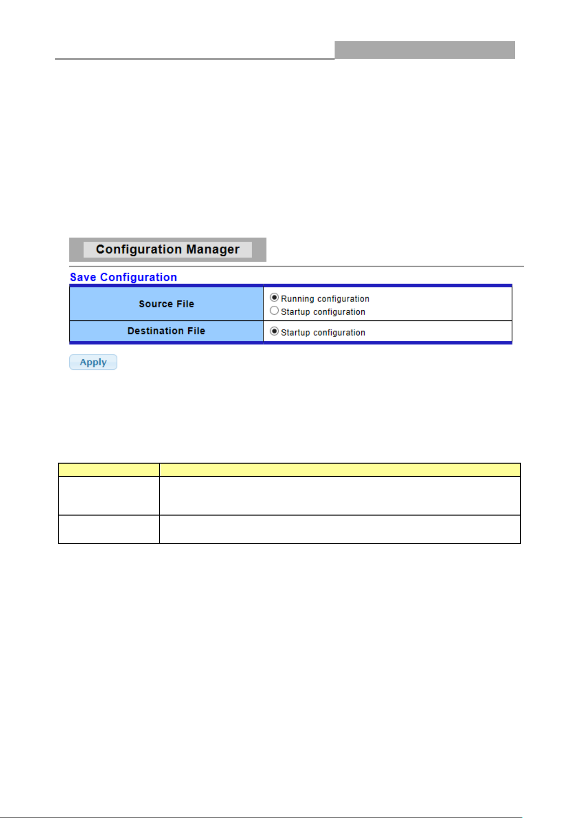
Source File
Select upgrade method
Running configuration: Running configuration file
Startup configuration: Startup configuration file
Destination File
Select Upgrade Type
Startup Configuration: Startup configuration file
2.3 SAVE LOGOUT REBOOT
2.3.1 SAVE
2.3.1.1Saving running configurations
Click SAVE-> Save Configuration to FLASH to view the screen as shown next. This page allow
user to copy running configuration, startup configuration or backup configuration to startup
configuration or backup configuration.
Configuration Manager Page
Configuration Manager Fields
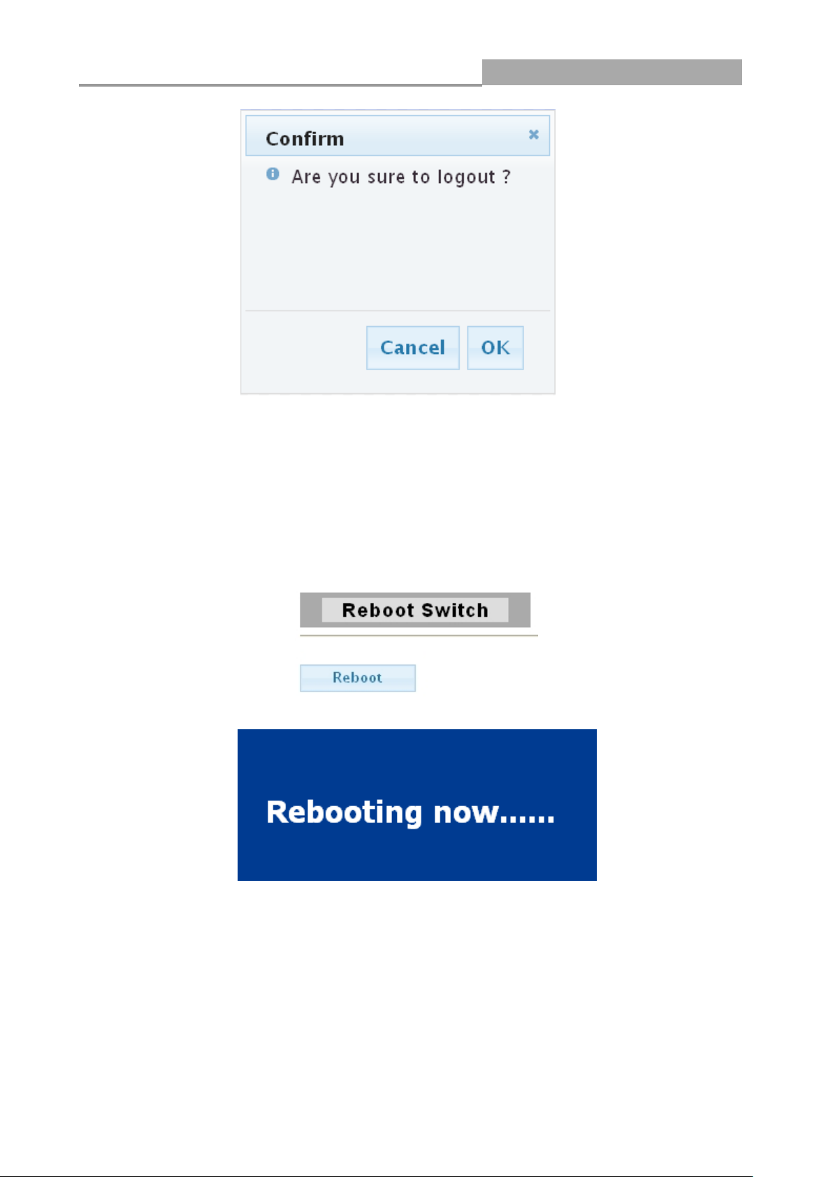
2.3.2 LOGOUT
Click Logout to exit the web configurator. You have to log in with your password again after you log
out, if there is any. This is recommended after you finish a management session for security
reasons.
Web Managed GbE Switch
16
2.3.3 REBOOT
Reboot allows you to restart the switch without physically turning the power off.
Follow the steps below to reboot the switch.
1. Click REBOOT to view the screen as shown next.
2. Click Reboot button, then the following interface pops up.
3. When it finished, the switch has been restarted.
Web Managed GbE Switch
17
LABEL
DESCRIPTION
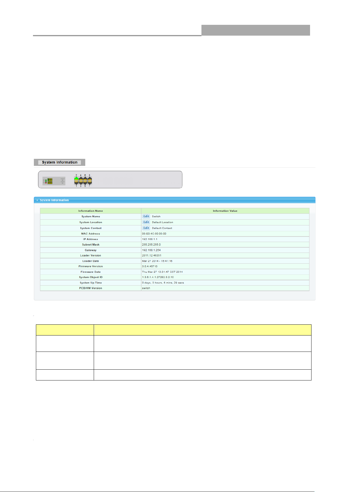
System Name
System name of the switch. This name will also use as CLI prefix of
each line. (“Switch>” or “Switch#”)
System
Location
System location of the switch.
System Contact
System contact of the switch.
Chapter 3 Web Management Configuration
3.1 Status
Use the Status pages to view system information and status.
3.1.1 System Information
In the navigation panel, click Status > System Information to display the screen as shown below.
This page allow user to configure and browse some system information such as MAC address, IP
address, loader version and firmware version and so on.
With “Edit”button in the table,user could configure the field value.
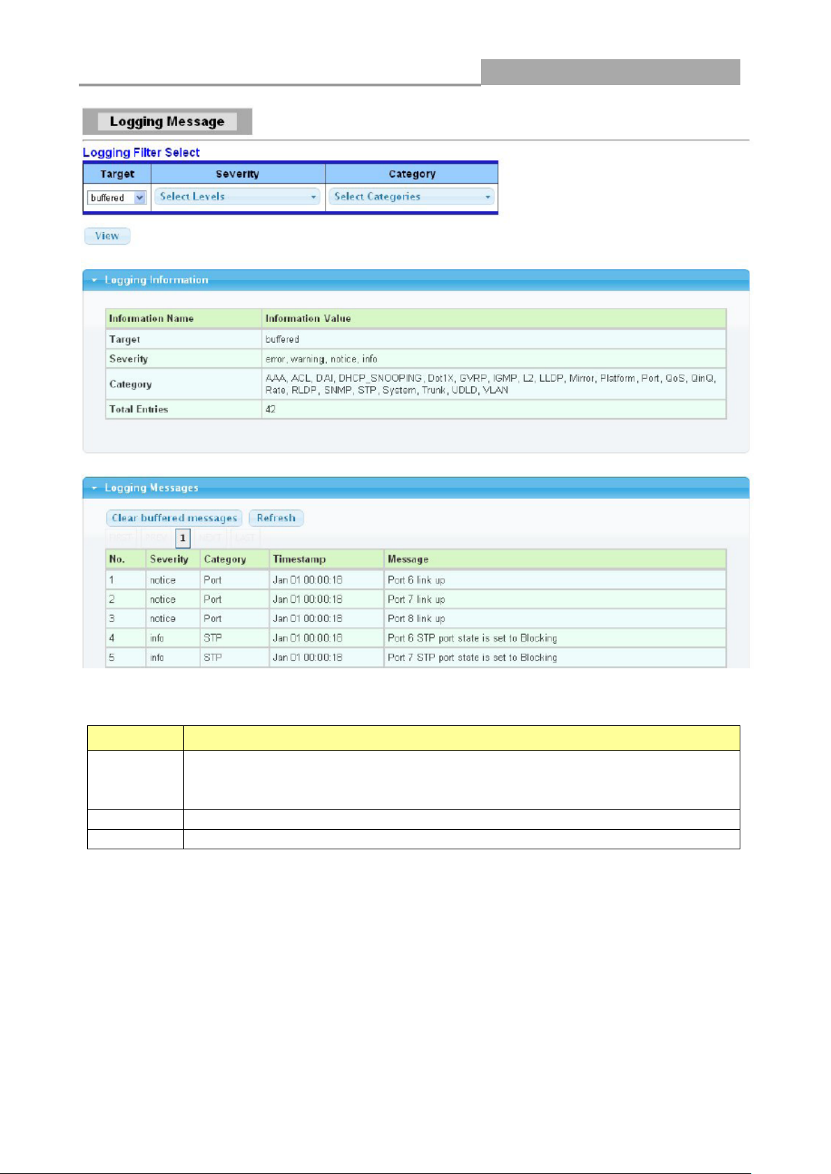
3.1.2 Logging Message
Use this screen to display the switch logs. Click Status > Logging Message in the navigation panel
to display the screen as shown below.
Web Managed GbE Switch
18
LABEL
DESCRIPTION
Target
Select the log message source to show on the table
Buffered: Logs store in the device buffer.
FLASH: Logs store in the device flash.
Severity
Select severity to filter log messages.
Category
Select category to filter log messages.
The following table describes the labels in this screen.
3.1.3 Port
The Port configuration page displays port summary and status information.
3.1.3.1 Port Counters
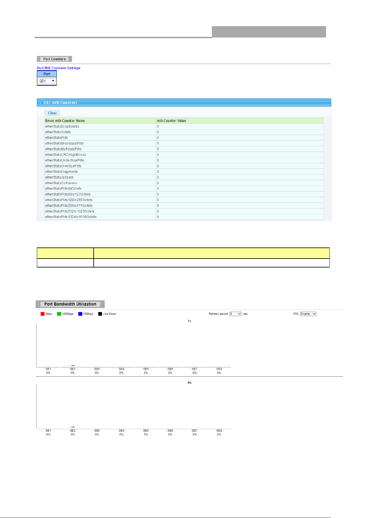
Use this screen to display the Switch port statistics. Click Status->Port > Port Counters to view the
screen as shown next.
Web Managed GbE Switch
19
LABEL
DESCRIPTION
Port
This identifies the Ethernet port.
The following table describes the labels in this screen.
3.1.3.2 Bandwidth Utilization
Web Managed GbE Switch
20
LABEL
DESCRIPTION
Refresh Period
Refresh the web page every period of seconds
IFG
Inter frame gap in bandwidth calculation
Enable: Add inter frame gap to bandwidth calculation
Disable: Remove inter frame gap to bandwidth
calculation
LABEL
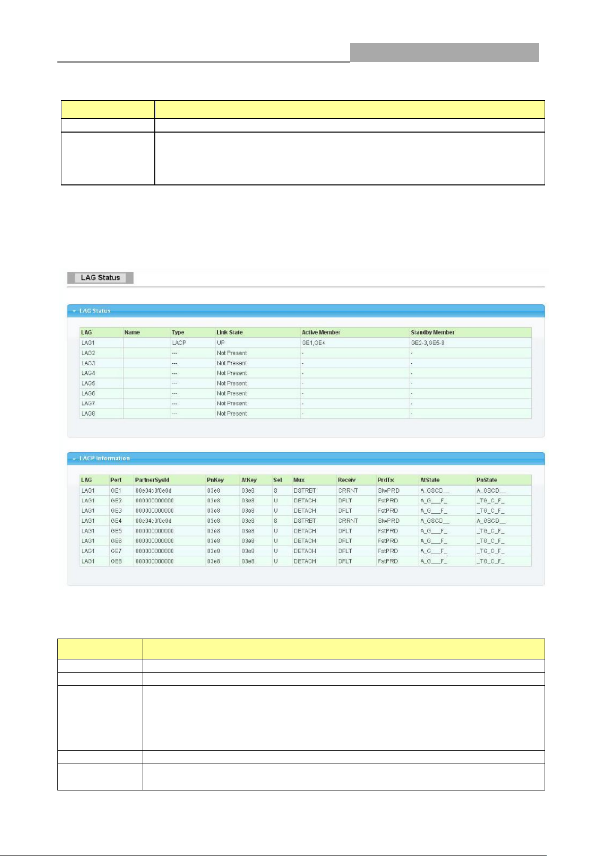
DESCRIPTION
LAG
LAG Name
Name
LAG port description
Type
The type of the LAG
Static: The groups of ports assigned to a static LAG are always active
members.
LACP: The groups of ports assigned to dynamic LAG are candidate
ports. LACP determines which candidate ports are active member ports.
Link State
LAG port link status
Active
Member
Active member ports of the LAG
The following table describes the labels in this screen.
3.1.4 Link Aggregation
Click Status > Link Aggregation in the navigation panel to view the screen as shown below.
The following table describes the labels in this screen.
LAG Status Field:
Web Managed GbE Switch
21
Standby
Member
Inactive or candidate member ports of the LAG
LABEL
DESCRIPTION
LAG
LAG Name
Port
Member port name.
PartnerSysId
The system ID of link partner. This field would be updated when the port
receives LACP PDU from link partner.
PnKey
Port key of partner. This field would be updated when the port receives LACP
PDU from link partner.
AtKey
Port key of actor. The key is designed to be the same as trunk ID.
Sel
LACP selection logic status of the port. “S” means selected, “U” means
unselected, and “D” means standby.
Mux
LACP mux state machine status of the port. “DETACH” means the port is in
detach state, “WAIT” means waiting state, “ATTACH” means attach state,
“CLLCT”
Receiv
LACP receive state machine status of the port. “INIT” means the port is in
initialize state, “PORTds” means port disabled state, “EXPR” means expired
state, “LACPds” means LACP disabled state, “DFLT” means defaulted state,
“CRRNT” means current state.
PrdTx
LACP periodic transmission state machine status of the port. “no PRD” means
the port is in no periodic state, “FstPRD” means fast periodic state, “SlwPRD”
means slow periodic state, “PrdTX” means periodic TX state.
AtState
The actor state field of LACP PDU description. The field from left to right
describes: “LACP_Activity”, “LACP_Timeout”, “Aggregation”,
“Synchronization”, “Collecting”, “Distributing”, “Defaulted”, and “Expired”. The
contents could be true or false. If the contents are false, the web shows “_”; if
the contents are true, the web shows “A”, “T”, “G”, “S”, “C”, “D”, “F” and “E” for
each content respectively.
PnState
The partner state field of LACP PDU description. The field from left to right
describes: “LACP_Activity”, “LACP_Timeout”, “Aggregation”,
“Synchronization”, “Collecting”, “Distributing”, “Defaulted”, and “Expired”. The
contents could be true or false. If the contents are false, the web shows “_”; if
the contents are true, the web shows “A”, “T”, “G”, “S”, “C”, “D”, “F” and “E” for
each content respectively.
LACP Status Field:
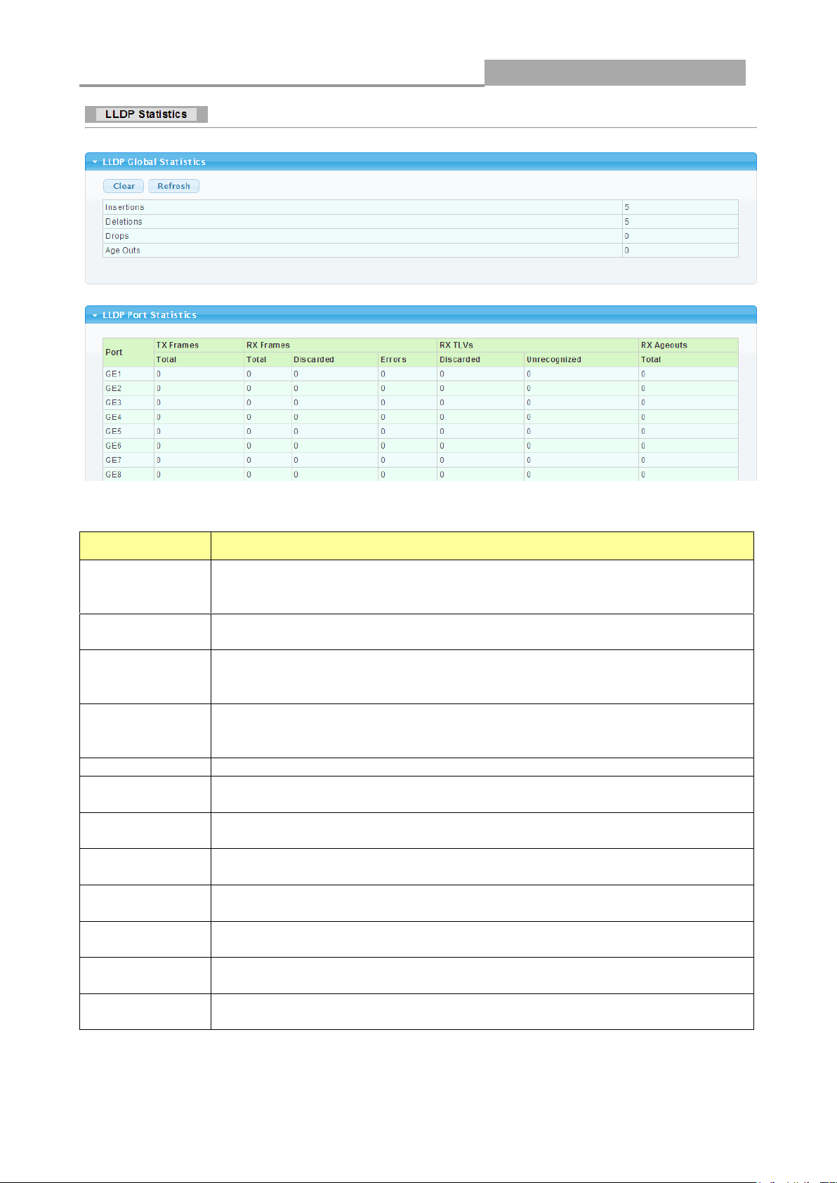
3.1.5 LLCP Statistics
Click Status > LLDP Statistics. The Link Layer Discovery Protocol (LLDP) Statistics page
displays summary and per-port information for LLDP frames transmitted and received on the switch.
Web Managed GbE Switch
22
LABEL
DESCRIPTION
Insertions
The number of times the complete set of information advertised by a
particular MAC Service Access Point (MSAP) has been inserted into tables
associated with the remote systems.
Deletions
The number of times the complete set of information advertised by MSAP
has been deleted from tables associated with the remote systems.
Drops
The number of times the complete set of information advertised by MSAP
could not be entered into tables associated with the remote systems
because of insufficient resources.
Age Outs
The number of times the complete set of information advertised by MSAP
has been deleted from tables associated with the remote systems because
the information timeliness interval has expired.
Port
Interface or port number.
TX Frames
Total
Number of LLDP frames transmitted on the corresponding port.
RX Frames
Total
Number of LLDP frames received by this LLDP agent on the corresponding
port, while the LLDP agent is enabled.
RX Frames
Discarded
Number of LLDP frames discarded for any reason by the LLDP agent on the
corresponding port.
RX Frames
Errors
Number of invalid LLDP frames received by the LLDP agent on the
corresponding port, while the LLDP agent is enabled.
RX TLVs
Discarded
Number of TLVs of LLDP frames discarded for any reason by the LLDP
agent on the corresponding port.
RX TLVs
Unrecognized
Number of TLVs of LLDP frames that are unrecognized while the LLDP
agent is enabled
RX Ageouts
Total
Number of age out LLDP frames.
The following table describes the labels in this screen.
Web Managed GbE Switch
23
LABEL
DESCRIPTION
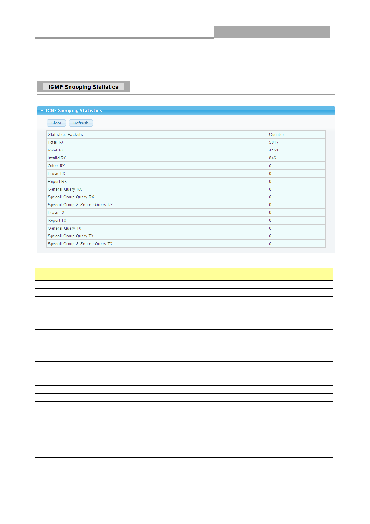
Total RX
This field displays the total amount of RX
Valid RX
This field displays the total amount of valid RX.
Invalid RX
This field displays the total amount of invalid RX.
Other RX
This field displays the total amount of other RX.
Leave RX
This field displays the total amount of leave RX.
Report RX
This field displays the total amount of report RX.
General Query
RX
This field displays the total amount of general query RX.
Special Group
Query RX
This field displays the total amount of Special Group query RX.
Special Group
& Source
Query RX
This field displays the total amount of Special Group & Source query RX.
Leave TX
This field displays the total amount of leave TX.
Report TX
This field displays the total amount of report TX.
General Query
TX
This field displays the total amount of general query TX.
Special Group
Query TX
This field displays the total amount of Special Group query TX.
Special Group
& Source
Query TX
This field displays the total amount of Special Group & Source query TX.
3.1.6 IGMP Snooping Statistics
Click Status > IGMP Snooping Statistics in the navigation panel to view the screen as shown
below.
The following table describes the labels in this screen.
Web Managed GbE Switch
24
LABEL
DESCRIPTION
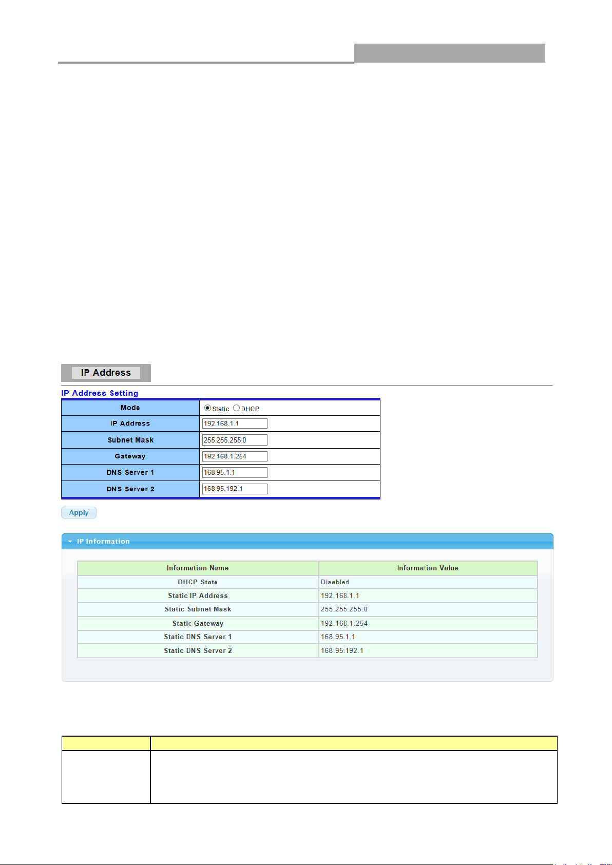
Mode
Select the mode of network connection
Static: Enable static IP address.
DHCP: Enable DHCP to obtain IP information from a DHCP server on the
network.
3.2 Network
Use the Network pages to configure settings for the switch network interface and how the switch
connects to a remote server to get services.
3.2.1 IP Address
Use the IP Setting screen to configure the switch IP address and the default gateway device. The
gateway field specifies the IP address of the gateway (next hop) for outgoing traffic.
The switch needs an IP address for it to be managed over the network. The factory default IP
address is 192.168.1.1. The subnet mask specifies the network number portion of an IP address.
The factory default subnet mask is 255.255.255.0.
Click Network > IP Address in the navigation panel to display the screen as shown below.
The following table describes the labels in this screen.

Web Managed GbE Switch
25
IP Address
Enter the IP address of your switch in dotted decimal notation for example
192.168.1.1. If static mode is enabled, enter IP address in this field.
Subnet Mask
Enter the IP subnet mask of your switch in dotted decimal notation for
example 255.255.255.0. If static mode is enabled, enter subnet mask in this
field.
Gateway
Enter the IP address of the gateway in dotted decimal notation. If static mode
is enabled, enter gateway address in this field.
DNS Server 1
If static mode is enabled, enter primary DNS server address in this field.
DNS Server 2
If static mode is enabled, enter secondary DNS server address in this field.
Apply
Click Apply to save your changes to the switch.
LABEL
DESCRIPTION
Auto
Configuration
Select Enable or Disable this function.
IPv6 Address
Enter the IPv6 address of your switch. If auto configuration mode is disabled,
enter IPv6 address in this field.
Gateway
Enter the IP address of the gateway in dotted decimal notation. If auto
configuration mode is disabled, enter IPv6 gateway address in this field.
DHCPv6
DHCPv6 client state.
3.2.2 IPv6 Address
Click Network> IPv6 Address in the navigation panel to display the screen as shown below.
The following table describes the labels in this screen.
IPv6 Information Filed:
Web Managed GbE Switch
26
Client
Enable: Enable DHCPv6 client function.
Disable: Disable DHCPv6 client function
Apply
Click Apply to save your changes to the switch.
LABEL
DESCRIPTION
Auto
Configuration
It displays whether the auto configuration function is opened or not.
IPv6 In Use
Address
It displays the in use address information of IPv6.
IPv6 In Use
Router
It displays the in use router information of IPv6.
IPv6 Static
Address
It displays the static address of IPv6.
IPv6 Static
router
It displays the static router of IPv6.
DHCPv6
Client
It displays the DHCPv6 Client Status.
LABEL
DESCRIPTION
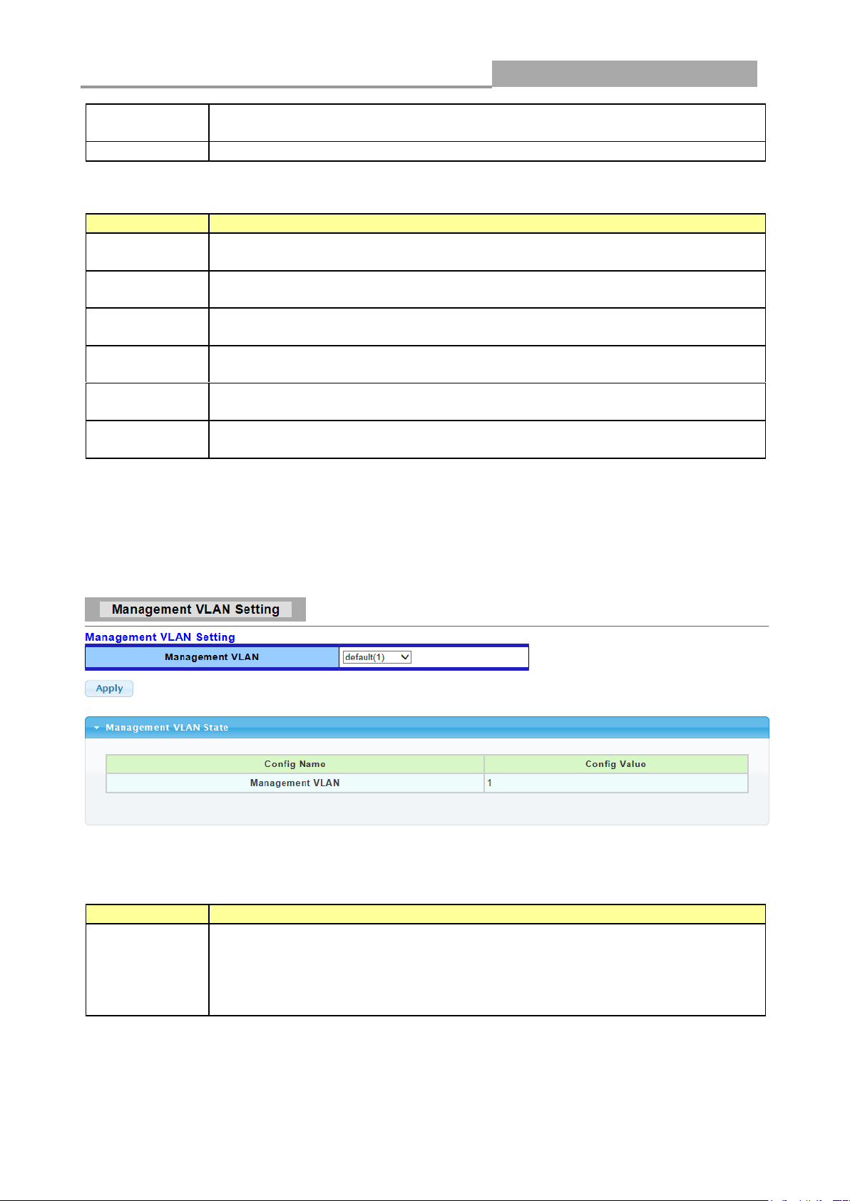
Management
VLAN
This allows the entry of a VLAN from which a management station will be
allowed to manage the device using TCP/IP (in-band via web manager or
Telnet). Management stations that are on VLANs other than the one selected
here will not be able to manage the Switch. The default management VLAN is
VLAN 1.
IPv6 Address Setting Filed:
3.2.3 Management VLAN
Click Network> Management VLAN in the navigation panel to display the screen as shown below.
The following table describes the labels in this screen.
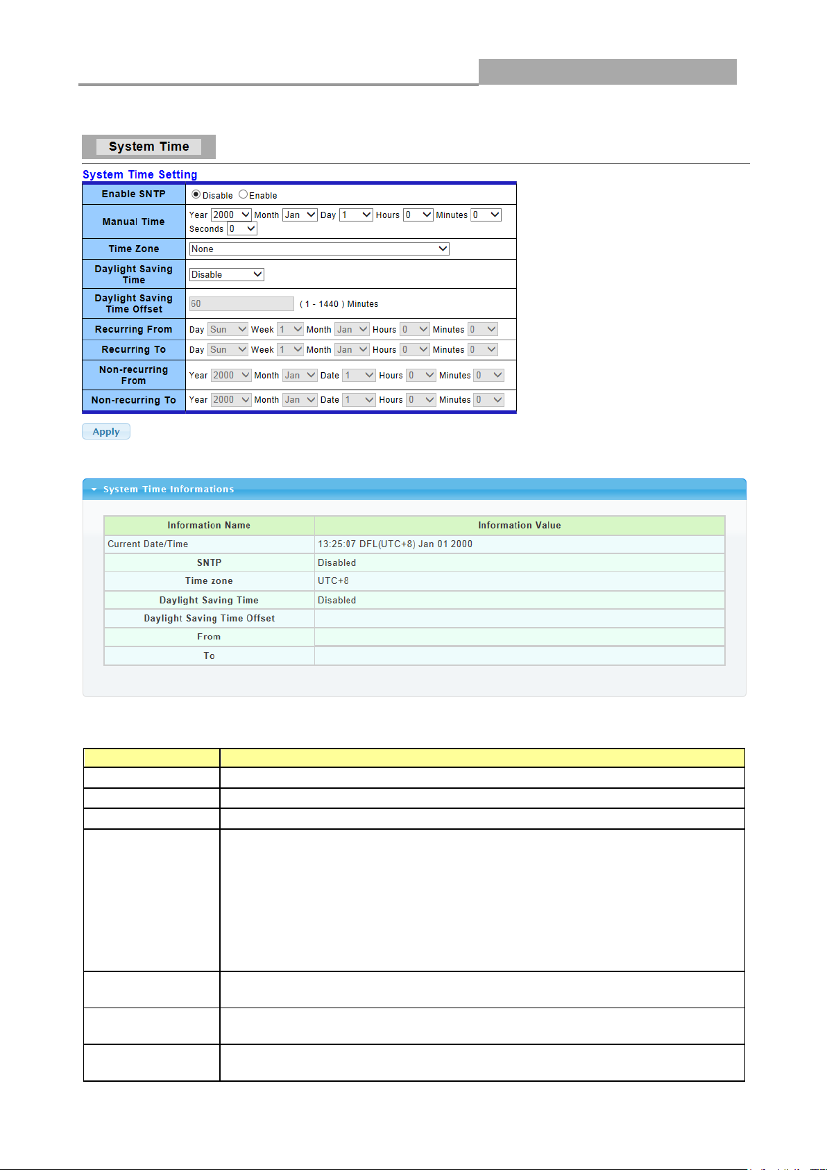
3.2.4 Time Settings
Web Managed GbE Switch
27
LABEL
DESCRIPTION
Enable SNTP
Select the radio button to enable or disable using SNTP server.
Manual Time
Specify static time.
Time Zone
Select a time zone
Daylight Saving
Time
Select the mode of daylight saving time.
Disable: Disable daylight saving time.
Recurring: Using recurring mode of daylight saving time.
Non-Recurring: Using non-recurring mode of daylight saving time.
USA: Using daylight saving time in the United States that starts on the
second Sunday of March and ends on the first Sunday of November
European: Using daylight saving time in the Europe that starts on the
last Sunday
Daylight Saving
Time Offset
Specify the adjust offset of daylight saving time.
Recurring From
Specify the starting time of recurring daylight saving time. This
field available when selecting “Recurring” mode.
Recurring To
Specify the ending time of recurring daylight saving time. This field available
when selecting “Recurring” mode.
Click Network> Time Settings in the navigation panel to display the screen as shown below.
The following table describes the labels in this screen.
Web Managed GbE Switch
28
Non-recurring
From
Specify the starting time of non-recurring daylight saving time.
This field available when selecting “Non-Recurring” mode.
Non recurring
To
Specify the ending time of recurring daylight saving time. This
field available when selecting “Non-Recurring” mode.
Apply
Click Apply to save your changes to the switch.
LABEL
DESCRIPTION
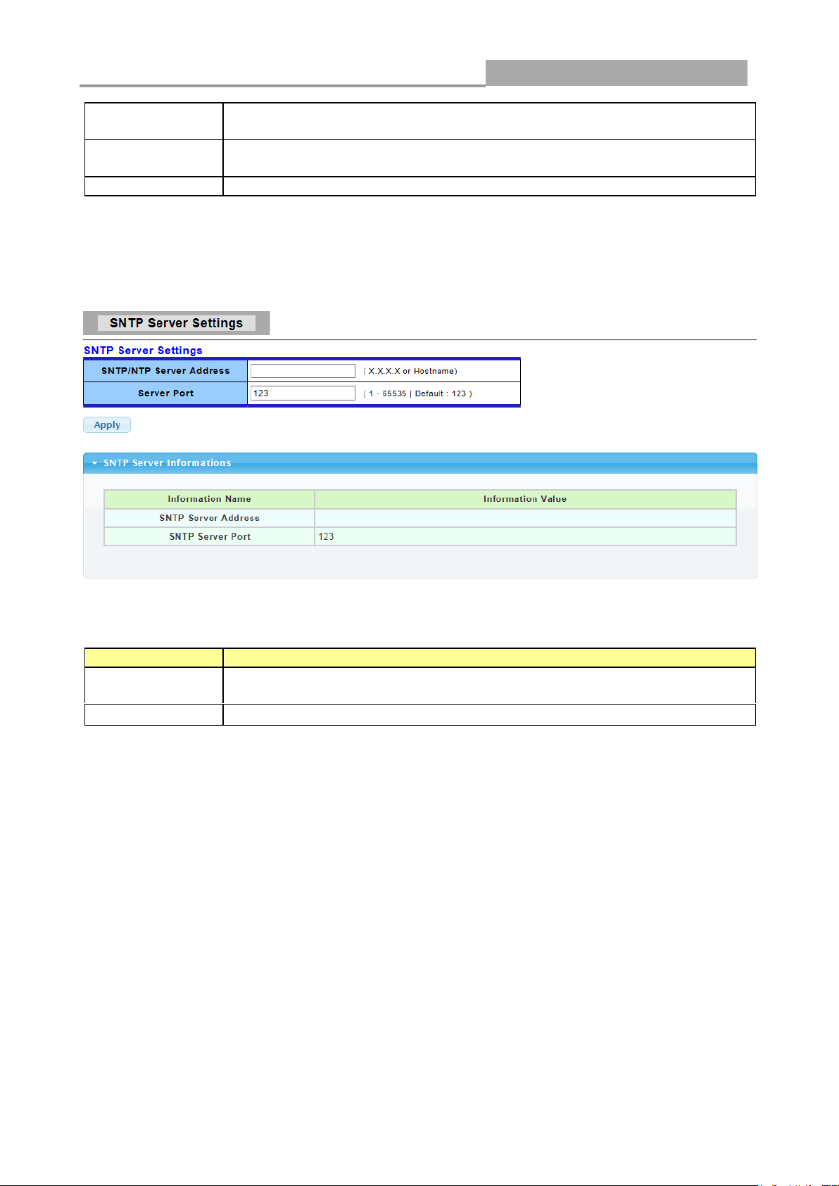
SNTP/NTP
Server Address
Input IP address or hostname of time server.
Server port
Input time server port number. Default is 123.
3.2.5 SNTP Settings
Click Network> Time Settings in the navigation panel to display the screen as shown below.
The following table describes the labels in this screen.
3.3 Switching
Use the Switching pages to configure settings for the switch ports, trunk, Layer 2 protocols and
other switch features.
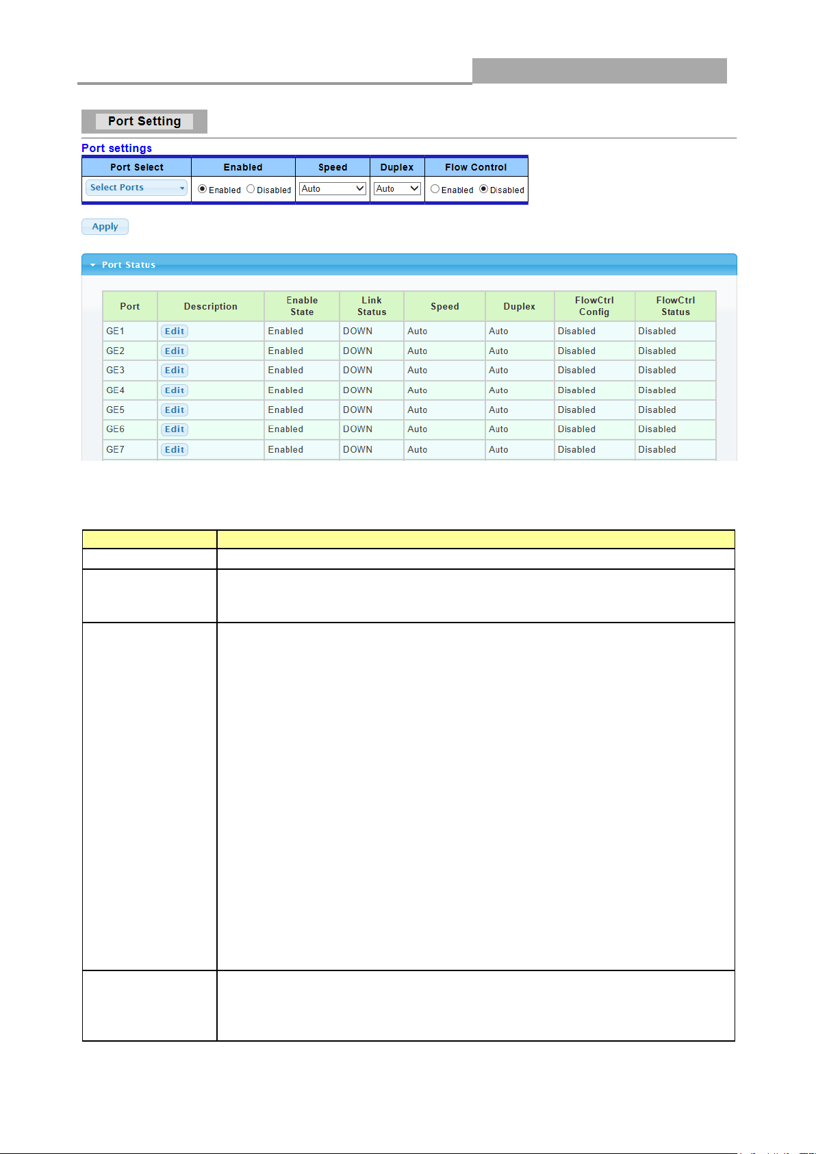
3.3.1 Port Setting
This page allow user to configure switch port settings and show port current status.
Click Switching > Port Setting in the navigation panel to display the screen as shown below.
Web Managed GbE Switch
29
LABEL
DESCRIPTION
Port Select
Select the port(s) from the list box that you will change the port settings for.
Enabled
Select Enable from the drop-down box to enable a port. The factory
default for all ports is enabled. A port must be enabled for data
transmission to occur. Select Disable to not use a port.
Speed
Port speed capabilities:
Auto: Auto speed with all capabilities.
Auto-10M: Auto speed with 10M ability only.
Auto-100M: Auto speed with 100M ability only.
Auto-1000M: Auto speed with 1000M ability only.
Auto-10/100M: Auto speed with 10/100M ability.
10M: Force speed with 10M ability.
100M: Force speed with 100M ability.
1000M: Force speed with 1000M ability.
Selecting Auto (auto-negotiation) allows one port to negotiate with a peer
port automatically to obtain the connection speed and duplex mode that
both ends support. When auto-negotiation is turned on, a port on the
switch negotiates with the peer automatically to determine the connection
speed and duplex mode. If the peer port does not support auto-negotiation
or turns off this feature, the switch determines the connection speed by
detecting the signal on the cable and using half duplex mode. When the
switch’s auto-negotiation is turned off, a port uses the pre-configured
speed and duplex mode when making a connection, thus requiring you to
make sure that the settings of the peer port are the same in order to
connect.
Duplex
Port duplex capabilities:
Auto: Auto duplex with all capabilities.
Half: Auto speed with 10/100M ability only.
Full: Auto speed with 10/100/1000M ability only.
The following table describes the labels in this screen.
Web Managed GbE Switch
30
Flow Control
A concentration of traffic on a port decreases port bandwidth and
overflows buffer memory causing packet discards and frame losses. Flow
Control is used to regulate transmission of signals to match the bandwidth
of the receiving port. The switch uses IEEE802.3x flow control in full
duplex mode and backpressure flow control in half duplex mode.
IEEE802.3x flow control is used in full duplex mode to send a pause signal
to the sending port, causing it to temporarily stop sending signals when the
receiving port memory buffers fill. Back Pressure flow control is typically
used in half duplex mode to send a "collision" signal to the sending port
(mimicking a state of packet collision) causing the sending port to
temporarily stop sending signals and resend later.
Select “Enabled” to enable it. Or select “Disabled” to disable it.
Apply
Click Apply to save your changes to the switch.
Flow Control
Config
The Config column displays if Flow Control has been configured to be
turned On or Off for the port.
Flow Control
Status
The column displays the port’s current Flow Control status.
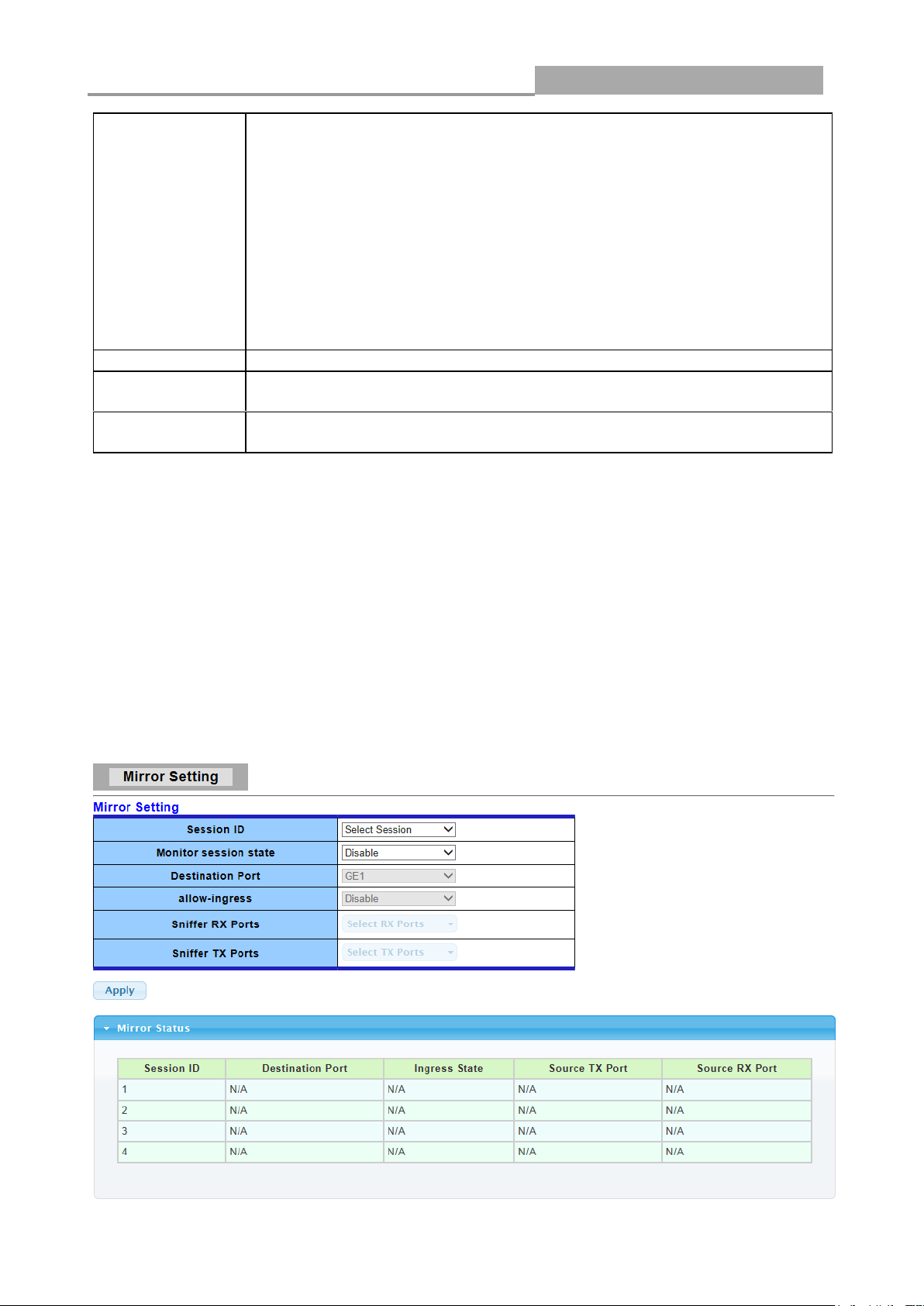
3.3.2 Port Mirroring
The Mirror function copies all the packets that are transmitted by the source port to the destination
port. It allows administrators to analyze and monitor the traffic of the monitored ports.
The Mirror Configuration steps are as follows:
Click Switching > Mirror > Local Mirror Setting in the navigation panel to display the screen as
shown below.

Web Managed GbE Switch
31
LABEL
DESCRIPTION
Session ID
Select mirror session ID
Monitor session
state
Select mirror session state : port-base mirror or disable
Destination Port
Select mirror session destination port
Allow-ingress
Select destination port ingress state.
Sniffer Rx ports
Select mirror session source rx ports only select portbased-enabled state,
this field is valid only when “Monitor session state” is port-base mirror
Sniffer Tx ports
Select mirror session source tx ports only select portbased-enabled state,
this field is valid only when “Monitor session state” is port-base mirror
Apply
Click Apply to save your changes to the switch.
LABEL
DESCRIPTION
Load Balance
Algorithm
Select the LAG load balance distribution algorithm
MAC Address: Based on source and destination MAC address for all
packets
IP/MAC Address: Based on source and destination IP addresses for IP
packet, and source and destination MAC address for non-IP packets.
Apply
Click Apply to save your changes to the switch.
The following table describes the labels in this screen.
3.3.3 Link Aggregation
3.3.3.1 LAG Setting
Click Switching> Link Aggregation > LAG Setting in the navigation panel to view the screen as
shown below.
The following table describes the labels in this screen.

Web Managed GbE Switch
32
LABEL
DESCRIPTION
LAG
Select the LAG to be configured.
Name
LAG port description
Type
Select the type of the LAG
Static: The group of ports assigned to a static LAG are always active
members.
LACP: The group of ports assigned to dynamic LAG are candidate ports.
LACP determines which candidate ports are active member ports.
Ports
Select the trunk member ports in this field. There are the following limitations
for choosing the member ports:
All ports in a LAG must be of the same media type.
To add a port to the LAG, it cannot belong to any VLAN except the
default VLAN.
Ports in a LAG must not be assigned to another LAG.
Ports in a LAG must not be a mirroring port.
No more than eight ports are assigned to a LAG.
When a port is added to a LAG, the configuration of the LAG is applied
to the port. When the port is removed from the LAG, its original
configuration is reapplied.
There could be at most 8 member ports in a trunk.
Apply
Click Apply to save your changes to the switch.
3.3.3.2 LAG Management
Click Switching> Link Aggregation > LAG Management in the navigation panel to view the
screen as shown below.
The following table describes the labels in this screen.
LAG Management Setting Field:

Web Managed GbE Switch
33
LABEL
DESCRIPTION
LAG
LAG Name
Name
LAG port description
Type
Select the type of the LAG
Static: The group of ports assigned to a static LAG are always active
members.
LACP: The group of ports assigned to dynamic LAG are candidate ports.
LACP determines which candidate ports are active member ports.
Link State
LAG port link status
Active
Member
Active member ports of the LAG
Standby
Member
Inactive or candidate member ports of the LAG
Modify
Click “Edit” button to edit LAG.
LABEL
DESCRIPTION
LAG
Select the LAG to be configured.
Name
LAG port description
Enabled
Port admin state.
Enabled: Enable the port.
LAG Management Information Field:
3.3.3.3 LAG Port Settings
Click Switching> Link Aggregation > LAG Port settings in the navigation panel to view the
screen as shown below.
The following table describes the labels in this screen.
LAG Port Setting Field:

Web Managed GbE Switch
34
Disabled: Disable the port.
Speed
Port speed capabilities.
Auto: Auto speed with all capabilities
Auto-10M: Auto speed with 10M ability only
Auto-100M: Auto speed with 100M ability only
Auto-1000M: Auto speed with 1000M ability only
Auto-10M/100M: Auto speed with 10M/100M
abilities
10M: Force speed with 10M ability
100M: Force speed with 100M ability
1000M: Force speed with 1000M ability
Flow Control
Port flow control.
Enabled: Enable flow control ability.
Disabled: Disable flow control ability.
Apply
Click Apply to save your changes to the switch.
LABEL
DESCRIPTION
LAG
LAG Name
Description
LAG port description
Port Type
Member port media type
Enable
LAG port admin state
Link Status
LAG port link status
Speed
Current LAG port speed
Duplex
Current LAG port duplex
Flow Control
Config
LAG port flow control configuration
Flow Control
Status
Current LAG port flow control state
LAG Port Status Field:
3.3.3.4 LACP Setting
Click Switching > Link Aggregation > LACP Setting to display the screen shown next.
LACP: Link Aggregation Control Protocol.
The following table describes the labels in this screen.

Web Managed GbE Switch
35
LABEL
DESCRIPTION
System Priority
Configure the system priority of LACP. This decides the system priority
field in LACP PDU.
Apply
Click Apply to save your changes to the Switch.
LABEL
DESCRIPTION
System Priority
LACP system priority value
LABEL
DESCRIPTION
Port Select
Select one or multiple ports to configure
Priority
Enter the LACP priority value of the port
Timeout
Select the periodic transmissions of LACP PDUs.
Long: Transmit LACP PDU with slow periodic (30s).
Short: Transmit LACPP DU with fast periodic (1s).
Apply
Click Apply to save your changes to the Switch.
LAG Setting Field:
LAG Information Field:
3.3.3.5 LACP Port Setting
Click Switching > Link Aggregation > LACP Port Setting to display the screen shown next.
The following table describes the labels in this screen.

Web Managed GbE Switch
36
LABEL
DESCRIPTION
VLAN LIST
Specify the VLAN list to apply the operation (add/delete/edit).
VLAN Action
Select the action of operation, To add/delete/edit the VLANs
VLAN Name
Prefix
Specify the prefix string of the VLAN name for new created VLANs. This
field is only available with add action.
Apply
Click Apply to save your changes to the Switch.
3.3.4 VLAN Management
A virtual local area network, virtual LAN or VLAN, is a group of hosts with a common set of
requirements that communicate as if they were attached to the same broadcast domain, regardless
of their physical location. A VLAN has the same attributes as a physical local area network (LAN),
but it allows for end stations to be grouped together even if they are not located on the same
network switch. VLAN membership can be configured through software instead of physically
relocating devices or connections.
3.3.4.1 Create VLAN
This page allow user to add, edit or delete VLAN settings.
Click Switching > VLAN Management > Create VLAN to access this screen below to configure
and view VLAN parameters for the switch.
The following table describes the related labels in this screen.
3.3.4.2 Interface Settings
This page allow user to configure VLAN Interface related settings.
Click Switching > VLAN Management > Interface Settings to access the screen below.

Web Managed GbE Switch
37
LABEL
DESCRIPTION
Port Select
Select specified port or all ports to configure Interface Settings.
Interface VLAN
Mode
Select the VLAN mode of the interface.
Hybrid: Support all functions as defined in IEEE 802.1Q
specification.
Access: Accepts only untagged frames and join an untagged VLAN.
Trunk: An untagged member of one VLAN at most, and is a tagged
member of zero or more VLANs.
PVID
Specify the port-based VLAN ID (1-4094). It’s only available with
Hybrid and Trunk mode.
Accepted Type
Specify the acceptable-frame-type of the specified interfaces. It’s only
available with Hybrid mode.
Ingress Filtering
Specify the status of ingress filtering. It’s only available with Hybrid mode.
Apply
Click Apply to save your changes to the Switch.
A PVID (Port VLAN ID) is a tag that adds to incoming untagged frames received on a port so that
the frames are forwarded to the VLAN group that the tag defines.
The following table describes the labels in this screen.
3.3.4.3 Port to VLAN
This page allow user to configure VLAN port setting.
Click Switching > VLAN Management > Port to VLAN to access the screen below.

Web Managed GbE Switch
38
LABEL
DESCRIPTION
VLAN ID
Select specified VLAN ID to configure Port to VLAN Settings.
Interface VLAN
Mode
Display the interface VLAN mode of this port.
Membership
Select the membership for this port with the specified VLAN ID.
Forbidden: Specify the port is forbidden in the VLAN.
Excluded: Specify the port is excluded in the VLAN.
Tagged: Specify the port is tagged in the VLAN.
Untagged: Specify the port is untagged in the VLAN.
PVID
Check this checkbox to select the VLAN ID to be the port-based
VLAN ID for this port.
The following table describes the labels in this screen.
3.3.4.4 Port VLAN Membership
This page allow user to configure Port VLAN Membership setting.
Click Switching > VLAN Management > Port VLAN Membership to access the screen below.
Use the Port VLAN Membership page to view membership information. Click “Edit” to edit selected
port to modify the membership.

Web Managed GbE Switch
39
LABEL
DESCRIPTION
Port
Display the interface of this port entry.
Mode
Display the interface VLAN mode of this port.
Administrative
VLANs
Display the administrative VLAN list of this port.
Operational
VLANs
Display the operational VLAN list of this port.
Modify
Click the `Edit` Button to edit the VLAN membership of this port.
The following table describes the labels in this screen.

Web Managed GbE Switch
40
LABEL
DESCRIPTION
Select VLAN
Select the left available VLANs to add or the right used VLANs to delete
for this port.
Tagging
Select the VLAN membership of the specified left VLANs for this port.
PVID
Check this checkbox to select the VLAN ID to be the port-based VLAN ID
for this port.
LABEL
DESCRIPTION
State
Select Voice VLAN state
Enable –Voice VLAN is enabled
Disable –Voice VLAN is disabled
Voice VLAN ID
Select Voice VLAN ID
Cos/802.1p
Select a value of vpt that will be advertised by LLDP-MED
1p remark
Select 1p remark state
Aging Time
Select value of aging time
The following table describes the labels in “Edit” screen.
3.3.4.5 Voice VLAN
This page allow user to configure Voice VLAN Properties setting.
Click Switching > VLAN Management > Voice VLAN > Properties to access the screen below.
The following table describes the labels in this screen.

Web Managed GbE Switch
41
LABEL
DESCRIPTION
OUI Address
Select oui address
Description
description of the specified MAC address to the voice VLAN OUI
table
3.3.4.6 Telephony OUI Mac setting
This page allow user to configure Voice VLAN Properties setting.
Click Switching > VLAN Management > Voice VLAN > Telephony OUI Mac setting to access
the screen below.
The following table describes the labels in this screen.
3.3.4.7 Telephony OUI Port Setting
This page allow user to configure Voice VLAN Properties setting.
Click Switching > VLAN Management > Voice VLAN > Telephony OUI Port Setting to access
the screen below.

Web Managed GbE Switch
42
LABEL
DESCRIPTION
Port
Select one or multiple ports to configure
State
Ingress/Egress type value
Cos Mode
Select port cos mode
Src QoS attributes are applied to packets with OUIs in the source MAC
address.
All QoS attributes are applied to packets that are classified to the Voice
VLAN.
The following table describes the labels in this screen.
3.3.5 EEE
3.3.5.1 SVLAN Setting
This page allow user to enable or disable port EEE (Energy Efficient Ethernet) function.
Click Switching > EEE to access the screen below.

Web Managed GbE Switch
43
LABEL
DESCRIPTION
Port
Select one or multiple ports to configure
State
Port EEE function.
Enabled: Enable EEE function
Disabled: Disable EEE function
Apply
Click Apply to save your changes to the switch.
The following table describes the labels in this screen.
3.3.6 Multicast
3.3.6.1 Properties
Click Switching > Multicast > Properties in the navigation panel to bring up the screen as shown
next.

Web Managed GbE Switch
44
LABEL
DESCRIPTION
Unknown
Multicast Action
Set the unknown multicast action
Drop: drop the unknown multicast data.
Flood: flood the unknown multicast data.
Router port: forward the unknown multicast data to router port.
IPv4 Forward
Method
Set the ipv4 multicast forward method.
MAC: forward method dmac+vid.
Src-Dst-Ip: forward method dip+sip.
Apply
Click Apply to save your changes to the switch.
The following table describes the labels in this screen.
3.3.6.2 IGMP Snooping
Use the Switching pages to configure settings for the switch network interface and how the switch
connects to a remote server to get services.
3.3.6.2.1 IGMP Setting
Click Switching > Multicast > IGMP Snooping > IGMP Setting to access the screen below.

Web Managed GbE Switch
45
LABEL
DESCRIPTION
IGMP Snooping
Status
Set the enabling status of IGMP functionality
Enable: Enable IGMP Snooping.
Disable: Disable IGMP Snooping.
IGMP Snooping
Version
Set the igmp snooping version
v2: Only support process igmp v2 packet.
v3: Support v3 basic and v2.
IGMP Snooping
Report
Suppression
Set the enabling status of IGMP v2 report suppression
Enable: Enable IGMP Snooping v2 report suppression.
Disable: Disable IGMP Snooping v2 report suppression.
Apply
Click Apply to save your changes to the switch.
Entry No
The IGMP entry number.
VLAN ID
The IGMP entry VLAN ID
IGMP Snooping
Operation Status
The enable status of IGMP VLAN functionality
Enabled: when IGMP Snooping enable and IGMP VLAN enable and
multicast filtering enable.
Disabled: when IGMP Snooping disable or IGMP VLAN disable or
multicast filtering disable.
Router Ports
Auto Learn
Set the enabling status of IGMP router port learning
Enable: Enable learning router port by query and PIM, DVRMP.
The following table describes the labels in this screen.

Web Managed GbE Switch
46
Disable: Disable learning dynamic router port.
Robustness
Variable
The Robustness Variable allows tuning for the expected packet loss on a
subnet.
Query Interval
The interval of querier send general query
Query Max
Response
Interval
In Membership Query Messages, it specifies the maximum allowed time
before sending a responding report in units of 1/10 second.
Last Member
Query count
The count that Querier-switch sends Group-Specific Queries when it
receives a Leave Group message for a group.
Last Member
Query Interval
The interval that Querier-switch sends Group-Specific Queries when it
receives a Leave Group message for a group.
Immediate leave
Leave the group when receive IGMP Leave message.
Enable: Enable Fastleave.
Disable: Disable Fastleave.
Edit
Click Edit to edit the IGMP Snooping Table.
LABEL
DESCRIPTION
VLAN ID
The IGMP VLAN ID
The following table describes the labels in “Edit” screen.

Web Managed GbE Switch
47
IGMP Snooping
Status
The admin enable status of IGMP VLAN functionality
Enable: IGMP VLAN enable.
Disable: IGMP VLAN disable.
Router Ports
Auto Learn
Set the enabling status of IGMP router port learning
Enable: Enable learning router port by query and PIM, DVRMP.
Disable: Disable learning dynamic router port.
Robustness
Variable
The Robustness Variable allows tuning for the expected packet loss on a
subnet.
Query Interval
The admin query interval
Oper Query
Interval
The operation query interval
Query Max
Response
Interval
The admin query max response interval
Oper Query Max
Response
Interval
The operating query max response interval
Last Member
Query count
The admin last member query count
Oper Last
Member Query
count
The operating last member query count
Last Member
Query Interval
The admin last member query interval.
Oper Last
Member Query
Interval
The operation last member query interval.
Immediate leave
Leave the group when receive IGMP Leave message.
Enable: Enable Fastleave.
Disable: Disable Fastleave.
Cancel
Click Cancel to cancel the change to switch.
Submit
Click Submit to submit the change to switch.
3.3.6.2.2 IGMP Querier Setting
This page allow user to configure querier settings on specific VLAN of IGMP Snooping.
Click Switching > Multicast > IGMP Snooping > IGMP Querier Setting to access the screen
below.

Web Managed GbE Switch
48
LABEL
DESCRIPTION
VLAN ID
Select the VLANs to configure.
Querier State
Set the enabling status of IGMP Querier Election on the chose VLANs
Enable: Enable IGMP Querier.
Disable: Disable IGMP Querier.
Snooping State
Set the query version of IGMP Querier Election on the chose VLANs
v2: Querier version 2.
v3: Querier version 3.
Apply
Click Apply to save your changes to the switch.
LABEL
DESCRIPTION
The following table describes the labels in this screen.
3.3.6.2.3 IGMP Static Group
This page allow user to set static group for IGMP.
Click Switching > Multicast > IGMP Snooping > IGMP Static Group to access the screen below.
The following table describes the labels in this screen.

Web Managed GbE Switch
49
VLAN ID
Select the VLANs to configure.
Group IP Address
The IP address of this group.
Member Ports
The member ports of this group.
Add
Click Add to add IGMP Group to the switch.
Edit
Click Edit to edit the IGMP Static Group.
Delete
Click Delete to edit the IGMP Static Group.
LABEL
DESCRIPTION
VLAN ID
The VLAN ID of static group.
Group Address
The group address
Include Ports
Select
The static member ports
Cancel
Click Cancel to cancel the change to switch.
Submit
Click Submit to submit the change to switch.
The following table describes the labels in “Edit” screen.
3.3.6.2.4 IGMP Group Table
This page allow user to browse IGMP group information of IGMP Snooping.
Click Switching > Multicast > IGMP Snooping > IGMP Group Table to access the screen below.

Web Managed GbE Switch
50
LABEL
DESCRIPTION
VLAN ID
The VLAN ID of this group.
Group IP Address
The group IP address of this group.
Member Port
The member ports of this group.
Type
The type of this group. Static or Dynamic.
Life(Sec)
The life time of this group.
LABEL
DESCRIPTION
VLAN ID
The VLAN ID of this group.
Port
The member ports of this group.
Expiry Time(Sec)
The expiry time of this group.
The following table describes the labels in this screen.
3.3.6.2.4 IGMP Router Table
This page allow user to browse IGMP group information of IGMP Snooping.
Click Switching > Multicast > IGMP Snooping > IGMP Router Table to access the screen below.
The following table describes the labels in this screen.
3.3.7 Jumbo Frame
This page allow user to configure switch port jumbo frame settings.
Click Switching > Jumbo Frame in the navigation panel to bring up the screen as shown next.

Web Managed GbE Switch
51
LABEL
DESCRIPTION
Jumbo Frame
(Bytes)
Jumbo frame size. The valid range is 1526 bytes – 9216 bytes.
Apply
Click Apply to save any changes to the switch.
The following table describes the labels in this screen.
3.3.8 STP
The Spanning Tree Protocol (STP) is a network protocol that ensures a loop-free topology for any
bridged Ethernet local area network.
3.3.8.1 STP Global Setting
Use the SPT Global Setting screen to activate one of the STP modes on the switch.
Click Switching > STP > STP Global Setting.

Web Managed GbE Switch
52
LABEL
DESCRIPTION
Enabled
Specify the STP status to be enabled/disabled on the switch.
BPDU Forward
Specify the BPDU forwarding action when the global STP is disabled.
Path Cost
Method
Specify the Cost Method of STP.
Force Version
Set the operating mode of STP:
STP-Compatible: IEEE 802.1D STP operation.
RSTP-Operation: IEEE 802.1w operation.
Apply
Click Apply to save your changes to the switch.
LABEL
DESCRIPTION
Port Select
Select the port(s) to change spanning tree protocol settings for.
Path Cost
Path cost is the cost of transmitting a frame on to a LAN through that port. It is
recommended to assign this value according to the speed of the bridge. The
slower the media, the higher the cost. Entering 0 means the switch will
The following table describes the labels in this screen.
3.3.8.2 STP Port Setting
This page allow user to configure general setting of STP port and browser CIST port status.
Click Switching > STP > STP Port Setting.
The following table describes the labels in this screen.

Web Managed GbE Switch
53
automatically assign a value.
Edge Port
Set the edge port configuration:
No: Force to false state ( as link to a bridge).
Yes: Force to true state ( as link to a host).
P2P MAC
Set the Point-to-Point port configuration:
No: Force to false state.
Yes: Force to true state.
Migrate
Force to try to use the new MST/RST BPDUs, and hence to test the hypothesis
that all legacy systems that do not understand the new BPDU formats have
been removed from the LAN segment on the port(s).
Apply
Click Apply to save your changes to the switch.
3.3.8.3 STP Bridge Setting
Click Switching > STP > STP Bridge Setting.

Web Managed GbE Switch
54
LABEL
DESCRIPTION
Priority
Set the STP Bridge Priority in the instance.
Max Hops
Set the value of the maximum number of hops in the region.
Forward
Delay
Set the delay time an interface takes to converge from blocking state to forwarding
state.
Max Age
Set the time any switch should wait before trying to change the STP topology after
unhearing Hello BPUD.
Tx Hold
Count
Set the Transmit Hold Count used to limit BPDU transmission rate.
Hello Time
Set the interval between periodic transmissions of BPDU by Designated Ports.
Apply
Click Apply to save your changes to the switch.
The following table describes the labels in this screen.
3.3.8.4 STP Port Advanced (CIST Port) Setting
This page allow user to configure gener setting of STP CIST port and browser CIST port status.
Click Switching > STP > STP Port Advanced Setting.

Web Managed GbE Switch
55
LABEL
DESCRIPTION
Port Select
Select the port list to specify which ports should apply this setting.
Priority
Set the Port Priority to the selected ports in the CIST instance.
Apply
Click Apply to save your changes to the switch.
The following table describes the labels in this screen.
3.3.8.5 STP Statistics
This page allow user to browser general statistics of STP.
Click Switching > STP > STP Statistics.

Web Managed GbE Switch
56
LABEL
DESCRIPTION
Port
It displays the port number.
Configuration
BDPUs
Received
It displays the configuration BDPUs received.
TCN BDPUs
Received
It displays the TCN BDPUs received.
Configuration
BDPUs
Transmitted
It displays the configuration BDPUs transmitted.
TCN BDPUs
Transmitted
It displays the Multiple Spanning Tree Protocol (MSTP) BDPUs transmitted.
The following table describes the labels in this screen.
3.4 MAC Address Table
Use the MAC Address Table pages to show dynamic MAC table and configure settings for static
MAC entries.
3.4.1 Static MAC Setting
Click Status > MAC Address Table > Static MAC Setting in the navigation panel to bring up the
screen as shown next.

Web Managed GbE Switch
57
LABEL
DESCRIPTION
MAC Address
Enter the MAC address in valid MAC address format, that is, six hexadecimal
character pairs. Static MAC addresses do not age out.
VLAN
Enter the VLAN identification number the MAC address belongs to.
Type
There are two types of MAC entry:
Unicast: add a unicast MAC entry.
Multicast: add a multicast MAC entry.
Port
If Type is unicast, select the port number of the MAC entry;
If Type is multicast, select the port list of the MAC entry.
Add
Click Add to add any port into the static MAC address table.
No.
This is the index number for the MAC address forwarding entries.
Delete
To delete any selected MAC address entries.
The following table describes the labels in this screen.
3.4.2 Dynamic Address Setting
Click Status > MAC Address Table > Dynamic Address Setting in the navigation panel to bring
up the screen as shown next.
The following table describes the labels in this screen.

Web Managed GbE Switch
58
LABEL
DESCRIPTION
Aging Time
<10-630> The Dynamic MAC address aging out value
Apply
Click Apply to save your changes to the switch.
LABEL
DESCRIPTION
Port
Select the port number to show or clear dynamic MAC entries. If not select
any port, VLAN and MAC address, the whole dynamic MAC table will be
displayed or cleared.
VLAN
This is the VLAN group to which the MAC address belongs. Select the
VLAN to show or clear dynamic MAC entries. If not select any port, VLAN
and MAC address, the whole dynamic MAC table will be displayed or
cleared.
MAC Address
This field displays the MAC address that will be forwarded. Select the MAC
address to show or clear dynamic MAC entries. If not select any port, VLAN
and MAC address, the whole dynamic MAC table will be displayed or
cleared.
View
Click the View button to display the logs according the criteria specified in
the fields above.
Clear
Click this button to remove any dynamically learned MAC address
forwarding entries.
Type
This shows whether the MAC address is Dynamic (learned by the Switch)
or Static Unicast (manually entered in the Static MAC Forwarding
screen).
Port
This field displays the port where the MAC address will be forwarded.
Add to Static
MAC table
Click this button to add any port into the static MAC table.
3.4.3 Dynamic Learned
Click Status > MAC Address Table > Dynamic Learned in the navigation panel to bring up the
screen as shown next.
The following table describes the labels in this screen.

Web Managed GbE Switch
59
LABEL
DESCRIPTION
Mode
Select the mode of storm control
pps: storm control rate calculates by packet-based
bps: storm control rate calculates by octet-based
Preamble &
IFG
Select the rate calculates w/o preamble & IFG (20 bytes)
Excluded: exclude preamble & IFG (20 bytes) when count ingress storm
control rate.
Included: include preamble & IFG (20 bytes) when count ingress storm
control rate.
Apply
Click Apply to save your changes to the Switch.
3.5 Security
Use the Security pages to configure settings for the switch security features.
3.5.1 Storm Control
3.5.1.1 Global Setting
Click Security > Storm Control > Global Setting to display the configuration screen as shown.
The following table describes the labels in this screen.
3.5.1.2 Port Setting
Click Security > Storm Control > Port Setting to display the configuration screen as shown.

Web Managed GbE Switch
60
LABEL
DESCRIPTION
Port
Select the setting ports
State
Select the state of setting
Disable: Disable the storm control function.
Enable: Enable the storm control function.
Action
Select the state of setting
Drop: Packets exceed storm control rate will be dropped.
Shutdown: Port exceed storm control rate will be shutdown.
Storm Type
Select the type of storm control
Broadcast: Broadcast packet
Unknown Unicast: Unknown unicast packet
Unknown Multicast: Unknown multicast packet
Rate
Value of storm control rate, Unit: pps (packet per-second) or Kbps
(Kbits per-second) depends on global mode setting.
The range is from 0 to 1000000.
Apply
Click Apply to save your changes to the Switch.
The following table describes the labels in this screen.
3.5.2 Protected Ports
This page allow user to configure protected port setting to prevent the selected ports from
communicate with each other.
Click Security > Protected Ports to display the configuration screen as shown.

Web Managed GbE Switch
61
LABEL
DESCRIPTION
Port List
To select the port to be protected.
Port Type
Configure port protect type:
Unprotected: Unprotected port can communicate with all ports.
Protected: Prevent protected ports from communicate with each
other.
Apply
Click Apply to save your changes to the Switch.
The following table describes the labels in this screen.
3.5.3 DoS
3.5.3.1 DoS Global Setting
This page allow user to configure DoS setting to enable/disable DoS function for Global Setting.
Click Security > DoS > DoS Global Setting to display the configuration screen as shown.

Web Managed GbE Switch
62
LABEL
DESCRIPTION
DMAC = SMAC
Both the source and the destination MAC addresses are the same.
Disabled: Disable the item DoS setting.
Enabled: Enable the item DoS setting.
Land
Both the source and the destination IPv4/IPv6 addresses are the same.
Disabled: Disable the item DoS setting.
The following table describes the labels in this screen.

Web Managed GbE Switch
63
Enabled: Enable the item DoS setting.
UDP Blat
Both the source and the destination UDP port are the same.
Disabled: Disable the item DoS setting.
Enabled: Enable the item DoS setting.
TCP Blat
Both the source and the destination TCP port are the same.
Disabled: Disable the item DoS setting.
Enabled: Enable the item DoS setting.
POD
Ping packets that length are larger than 65535 bytes.
Disabled: Disable the item DoS setting.
Enabled: Enable the item DoS setting.
IPv6 Min
Fragment
IPv6 fragmented packets (not including the last one) that payload length
less than 1240 bytes, and the Min length can be configured if needed.
Disabled: Disable the item DoS setting.
Enabled: Enable the item DoS setting.
ICMP Fragments
Fragmented ICMP packets.
Disabled: Disable the item DoS setting.
Enabled: Enable the item DoS setting.
IPv4 Ping Max
Size
IPv4 PING packet with the length.
Disabled: Disable the item DoS setting.
Enabled: Enable the item DoS setting.
Ipv6 Ping Max
Size
IPv6 PING packet with the length.
Disabled: Disable the item DoS setting.
Enabled: Enable the item DoS setting.
Ping Max Size
Setting
Ping packet Max Size Setting. The default value is 512 Bytes, it can be
configured if needed.
Smurf Attack
ICMP echo request packet that destination IPv4 address is broadcast
address. The default Netmask length is 0, and it can be configured if
needed.
Disabled: Disable the item DoS setting.
Enabled: Enable the item DoS setting.
TCP Min Hdr Size
TCP packet that header length is less than the configured value.
The default TCP Min Hdr Size is 20, it can be configured if needed.
Disabled: Disable the item DoS setting.
Enabled: Enable the item DoS setting.
TCPSYN( SPORT
<1024)
TCP SYN packets with source port less than 1024.
Disabled: Disable the item DoS setting.
Enabled: Enable the item DoS setting.
Null Scan Attack
TCP sequence number is zero, and all control flags are zeroes.
Disabled: Disable the item DoS setting.
Enabled: Enable the item DoS setting.
X-Mas Scan
Attack
TCP sequence number is zero, and the FIN/URG/PSH flags are set.
Disabled: Disable the item DoS setting.
Enabled: Enable the item DoS setting.
TCP SYN-FIN
Attack
A TCP packet with the SYN and FIN flags set.
Disabled: Disable the item DoS setting.
Enabled: Enable the item DoS setting.
TCP SYN-RST
Attack
A TCP packet with the SYN and RST flags set.
Disabled: Disable the item DoS setting.
Enabled: Enable the item DoS setting.
TCP
Fragment(Offset=
1)
Fragmented TCP packets.
Disabled: Disable the item DoS setting.
Enabled: Enable the item DoS setting.
Apply
Click Apply to save your changes to the Switch.

Web Managed GbE Switch
64
LABEL
DESCRIPTION
Port Select
Select one or multiple ports to configure.
DoS Protection
Configure port protect state
Disabled: Disable port DoS Protection function.
Enabled: Enable port DoS Protection function.
Apply
Click Apply to save your changes to the Switch.
3.5.3.2 DoS Port Setting
Click Security > DoS > DoS Port Setting to display the configuration screen as shown.
The following table describes the labels in this screen.
3.5.4 Access
3.5.4.1 Telnet
Telnet is the TCP/IP standard protocol for remote terminal service. TELNET allows a user at one
site to interact with a remote timesharing system at another site as if the user’s keyboard and
display connected directly to the remote machine.
To display Telnet web page, click Security > Access > Telnet

Web Managed GbE Switch
65
LABEL
DESCRIPTION
Telnet Service
Set Enabled to access telnet service or Disabled not to access telnet
service.
Disconnect
Click Disconnect to disconnect Telnet connection.
Apply
Click Apply to save your changes to the Switch.
LABEL
DESCRIPTION
HTTP Service
Support HTTP service
Enable: Enable HTTP service.
The following table describes the labels in this screen.
3.5.4.2 HTTP
HTTP is the acronym of Hyper Text Transfer Protocol.
To display HTTP web page, click Security > Access > HTTP
The following table describes the labels in this screen.

Web Managed GbE Switch
66
Disable: Disable HTTP service.
Session Timeout
Set session timeout minutes for user access WEB from HTTP protocol. If
user does not response after session timeout minute, WEBUI will logout
automatically. 0 minutes means never timeout.
Apply
Click Apply to save your changes to the Switch.
LABEL
DESCRIPTION
HTTPS Service
Support HTTPS service
Enable: Enable HTTPS service.
Disable: Disable HTTPS service.
Login
Authentication List
Select one of the login authentication lists we configured in “Login List”
page.
Session Timeout
Set session timeout minutes for user access WEB from HTTPS protocol.
If user does not response after session timeout minute, WEBUI will logout
automatically. 0 minutes means never timeout.
Apply
Click Apply to save your changes to the Switch.
3.5.4.3 HTTPS
HTTPS is the acronym of Hypertext Transfer Protocol over Secure Socket Layer.
To display HTTPS web page, click Security > Access > HTTPS
The following table describes the labels in this screen.
3.6 QoS
Use the QoS pages to configure settings for the switch QoS interface and how the switch connects
to a remote server to get services.

Web Managed GbE Switch
67
LABEL
DESCRIPTION
QoS Mode
Select the QoS operation mode.
Disable: Disable QoS
Basic: Set QoS to basic mode
Apply
Click Apply to save your changes to the switch.
3.6.1 General
3.6.1.1 QoS Properties
Use the QoS general pages to configure settings for both basic and advanced modes.
Click QoS > General > QoS Properties in the navigation panel to display the screen as shown
below.
The following table describes the labels in this screen.
3.6.1.2 Port Settings
Click QoS > General > Port Settings in the navigation panel to display the screen as shown below.

Web Managed GbE Switch
68
LABEL
DESCRIPTION
Port
Select one or multiple ports to configure
CoS Value
Set default CoS/802.1p priority value for the selected ports
Remark CoS
Enable/Disable CoS remark
Remark DSCP
Enable/Disable DSCP remark
Remark IP
Precedence
Enable/Disable IP Precedence remark
Apply
Click Apply to save your changes to the switch.
The following table describes the labels in this screen.
3.6.1.3 Queue Settings
Click QoS > General > Queue Settings in the navigation panel to display the screen as shown
below.

Web Managed GbE Switch
69
LABEL
DESCRIPTION
Queue
Queue ID to configure
Strict Priority
Set queue to strict priority type
WRR
Set queue to Weight round robin type
Weight
If the queue type is WRR, set the queue weight for the queue.
Apply
Click Apply to save your changes to the switch.
The following table describes the labels in this screen.
3.6.1.4 CoS Mapping
Click QoS > General > CoS Mapping in the navigation panel to display the screen as shown
below.

Web Managed GbE Switch
70
LABEL
DESCRIPTION
Class of service
Class of service value
Queue
Select queue ID for the CoS value
Apply
Click Apply to save your changes to the switch.
Queue
Queue ID
Class of service
Select CoS Value for the Queue ID
The following table describes the labels in this screen.
3.6.1.5 DSCP Mapping
Click QoS > General > DSCP Mapping in the navigation panel to display the screen as shown
below.

Web Managed GbE Switch
71
LABEL
DESCRIPTION
DSCP
Select the DSCP value to mapping to the priority and drop precedence.
The DSCP range is 0 to 63.
Queue
Select queue ID for the DSCP value
Apply
Click Apply to save your changes to the switch.
Queue
Queue ID
DSCP
Select DSCP Value for the Queue ID
The following table describes the labels in this screen.
3.6.1.6 IP Precedence Mapping
Click QoS > General > IP Precedence Mapping in the navigation panel to display the screen as
shown below.

Web Managed GbE Switch
72
LABEL
DESCRIPTION
IP Precedence
IP Precedence value
Queue
Select queue ID for the IP Precedence value
Apply
Click Apply to save your changes to the switch.
Queue
Queue ID
IP Precedence
Select IP Precedence value for the queue ID
The following table describes the labels in this screen.
3.6.2 QoS Basic Mode
Use the QoS basic mode pages to configure settings for basic mode.

Web Managed GbE Switch
73
LABEL
DESCRIPTION
Trust Mode
Select the QoS operation mode.
CoS/802.1p: Traffic is mapped to queues based on the CoS field in the
VLAN tag, or based on the per-port default CoS value if there is no
VLAN tag on the incoming packet.
DSCP: All IP traffic is mapped to queues based on the DSCP field in the
IP header. If traffic is not IP traffic, it is mapped to the lowest priority
queue.
CoS/802.1p-DSCP: All IP traffic is mapped to queues based on the
DSCP field in the IP header. If traffic is not IP but has VLAN tag,
mapped to queues based on the CoS value in the VLAN tag.
IP Precedence: All IP traffic is mapped to queues based on the IP
Precedence field in the IP header. If traffic is not IP traffic, it is mapped
to the lowest priority queue.
None: All traffic is mapped to the lowest priority queue.
Apply
Click Apply to save your changes to the switch.
3.6.2.1 Global Settings
Click QoS > QoS Basic Mode > Global settings in the navigation panel to display the screen as
shown below.
The following table describes the labels in this screen.
3.6.2.2 Port Settings
Click QoS > QoS Basic Mode > Port settings in the navigation panel to display the screen as
shown below.

Web Managed GbE Switch
74
LABEL
DESCRIPTION
Port
Select one or multiple ports to configure
Apply
Click Apply to save your changes to the switch.
Trust
Select the port trust state.
Enabled: Traffic from this port will follow the global trust type.
Disabled: Traffic will always go to the lowest priority queue.
The following table describes the labels in this screen.
3.6.3 Rate Limit
Use the QoS basic mode pages to configure settings for basic mode.
3.6.3.1 Ingress Bandwidth Control Settings
Click QoS > Rate Limit > Ingress Bandwidth Control Settings in the navigation panel to display
the screen as shown below.

Web Managed GbE Switch
75
LABEL
DESCRIPTION
Port
Select one or multiple ports to configure
State
Enable/Disable ingress bandwidth control
Rate
Rate value,<0-1000000>,unit:16 Kbps
Apply
Click Apply to save your changes to the switch.
The following table describes the labels in this screen.
3.6.3.2 Egress Bandwidth Control Settings
Click QoS > Rate Limit > Egress Bandwidth Control Settings in the navigation panel to display
the screen as shown below.

Web Managed GbE Switch
76
LABEL
DESCRIPTION
Port
Select one or multiple ports to configure
State
Enable/Disable ingress bandwidth control
Rate
Rate value,<0-1000000>,unit:16 Kbps
Apply
Click Apply to save your changes to the switch.
The following table describes the labels in this screen.
3.6.3.3 Egress Queue
Click QoS > Rate Limit > Egress Queue in the navigation panel to display the screen as shown
below.

Web Managed GbE Switch
77
LABEL
DESCRIPTION
Port
Select one or multiple ports to configure
Queue
Select one queue to configure
State
Enable/Disable ingress bandwidth control
Rate
Rate value,<0-1000000>,unit:16 Kbps
Apply
Click Apply to save your changes to the switch.
The following table describes the labels in this screen.
3.7 Management
Use the Network pages to configure settings for the switch network interface and how the switch
connects to a remote server to get services.
3.7.1 LLDP
LLDP is a one-way protocol; there are no request/response sequences. Information is advertised by
stations implementing the transmit function, and is received and processed by stations
implementing the receive function. The LLDP category contains LLDP and LLDP-MED pages.
3.7.1.1 LLDP Global Setting
Click Management > LLDP > LLDP Global Setting to display the screen as shown next.

Web Managed GbE Switch
78
LABEL
DESCRIPTION
Enabled
Enable/ Disable LLDP protocol on this switch.
LLDP PDU
Disable Action
Select LLDP PDU handling action to be filtered, bridging or flooded when
LLDP is globally disabled.
Transmission
Interval
Select the interval at which frames are transmitted. The default is 30
seconds, and the valid range is 5–32768 seconds.
Holdtime
Multiplier
Select the multiplier on the transmit interval to assign to TTL (range 2–10,
default = 4).
Reinitialization
Delay
Select the delay before a re-initialization (range 1–10 seconds, default =
2).
Transmit Delay
Select the delay after an LLDP frame is sent (range 1–8192 seconds,
default = 3).
Apply
Click Apply to save your changes to the switch.
The following table describes the labels in this screen.
3.7.1.2 LLDP Port Setting
Click Management > LLDP > LLDP Port Setting to display the screen as shown next.

Web Managed GbE Switch
79
LABEL
DESCRIPTION
Port Select
Select specified port or all ports to configure LLDP state.
The following table describes the labels in this screen.

Web Managed GbE Switch
80
State
Select the transmission state of LLDP port interface.
Disable: Disable the transmission of LLDP PDUs.
RX Only: Receive LLDP PDUs only.
TX Only: Transmit LLDP PDUs only.
TX And RX: Transmit and receive LLDP PDUs both.
Apply
Click Apply to save your changes to the switch.
Port Select
Select specified port or all ports to configure optional TLVs.
Optional TLV
Select
Select the LLDP optional TLVs to be carried (multiple selection is
allowed).
System Name
Port Description
System Description
System Capability
802.3 MAC-PHY
802.3 Link Aggregation
802.3 Maximum Frame Size
Management Address
802.1 PVID
Apply
Click Apply to save your changes to the switch.
Port Select
Select specified port or all ports to configure VLAN Name.
VLAN Select
Select the VLAN Name ID to be carried (multiple selection is allowed).
Apply
Click Apply to save your changes to the switch.
3.7.1.3 LLDP Local Device
Use the LLDP Local Device page to view LLDP local device information. Click “detail” button on the
page to view detail information of the selected port.
Click Management > LLDP > LLDP Local Device to display the screen as shown next.

Web Managed GbE Switch
81

Web Managed GbE Switch
82
3.7.1.4 LLDP Remote Device
Click Management > LLDP > LLDP Remote Device to display the screen as shown next.
Use the LLDP Remote Device page to view LLDP neighbors information. Click “detail” to view
selected neighbor detail information.

Web Managed GbE Switch
83
3.7.1.5 LLDP Overloading
Click Management > LLDP > LLDP Overloading to display the screen as shown next.

Web Managed GbE Switch
84
LABEL
DESCRIPTION
Interface
This label shows the port you are viewing.
Total (Bytes)
This field displays the total in bytes.
Left to Send
(Bytes)
This field displays what is left to send in bytes.
Status
This field displays whether the Switch is overloading or not.
Mandatory TLVs
This field displays how many bytes used by mandatory TLVs.
802.3 TLVs
This field displays how many bytes used by 802.3 TLVs.
Optional TLVs
This field displays how many bytes used by optional TLVs.
802.1 TLVs
This field displays how many bytes used by 802.1 TLVs.
The following table describes the labels in this screen.
3.7.2 SNMP
3.7.2.1 SNMP Setting
Click Management > SNMP->SNMP Setting to display the screen as shown next.

Web Managed GbE Switch
85
LABEL
DESCRIPTION
State
SNMP daemon state:
Select Enabled to activate SNMP daemon.
Select Disabled to not use SNMP daemon.
Apply
Click Apply to save your changes to the switch.
LABEL
DESCRIPTION
Community
Enter a Community string, this will act as a password for requests from the
The following table describes the labels in this screen.
3.7.2.2 SNMP Community
Click Management > SNMP->SNMP Community to display the screen as shown next.
The following table describes the labels in this screen.

Web Managed GbE Switch
86
Name
management station.
Access Right
SNMP community type:
Read-Only: Read all objects only, it can allow the SNMP manager
using this string to collect information from the switch.
Read-Write: Read and write all objects, it can allow the SNMP
manager using this string to create or edit MIBs (configure settings on
the switch).
Add
Click Add to add any other community.
No
It displays the port number which in the community.
Community
Name
This field displays the community strings.
Access Right
This field displays the community string’s type. This will either be read-only
or read-write.
Delete
Click Delete to remove any selected community strings.
LABEL
DESCRIPTION
IP Address
Enter the IP addresses to send your SNMP traps to.
Community Name
Enter a Community string, which is the password sent with each trap to
the SNMP manager.
Add
Click Add to add any trap receiver.
IP Address
This field displays the IP address where the traps from the switch are
sent.
Community Name
This field displays the password which is sent with each trap to the
SNMP manager.
Version
Indicates the SNMP trap supported version. Possible versions are:
3.7.2.3 SNMP Trap Host
This page allow user to add or delete SNMP trap receiver IP address and community name.
Click Management > SNMP->SNMP Trap Host to display the screen as shown next.
The following table describes the labels in this screen.

Web Managed GbE Switch
87
v1: Set SNMP trap supported version 1.
v2c: Set SNMP trap supported version 2c.
Delete
Click Delete to remove any selected trap receiver entries.
LABEL
DESCRIPTION
Port
The Selected Port ID.
Copper Test
Click Copper to start the test.
3.8 Diagnostics
Use the Diagnostics pages to configure settings for the switch diagnostics feature or operating
diagnostic utilities.
3.8.1 Cable Diagnostics
3.8.1.1 Copper Test
Click Diagnostics > Cable Diagnostics > Copper Test to view the screen as shown next.
The following table describes the labels in this screen.
3.8.2 Ping Test
Click Diagnostics > Ping Test to view the screen as shown next.

Web Managed GbE Switch
88
LABEL
DESCRIPTION
IP Address
Enter the IP addresses of the test destination.
Count
It displays how many times to send ping request packet.
Enter a number between 1 and 5 as the count and the default
configuration is 4.
Interval
It displays time interval between each ping request packet.
Enter a number between 1 and 5 as the interval and the default
configuration is 1.
Size
It displays the size of ping packet.
Enter a number between 0 and 5120 as the size and the default
configuration is 56.
Ping Results
After ping finished, results will show in this field.
Apply
Click Apply to save your changes to the switch.
The following table describes the labels in this screen.
3.8.3 IPv6 Ping Test
Click Diagnostics > IPv6 Ping Test to view the screen as shown next.

Web Managed GbE Switch
89
LABEL
DESCRIPTION
IPv6 Address
Enter the IPv6 addresses of the test destination.
Count
It displays how many times to send ping request packet.
Enter a number between 1 and 5 as the count and the default
configuration is 4.
Interval
It displays time interval between each ping request packet.
Enter a number between 1 and 5 as the interval and the default
configuration is 1.
Size
It displays the size of ping packet.
Enter a number between 0 and 5120 as the size and the default
configuration is 56.
Ping Results
After ping finished, results will show in this field.
Apply
Click Apply to save your changes to the switch.
The following table describes the labels in this screen.
3.8.4 Logging Setting
3.8.4.1 Logging Service
Use this screen to display the switch logs.
Click Diagnostics > Logging Setting > Logging Service to view the screen as shown next.

Web Managed GbE Switch
90
LABEL
DESCRIPTION
Logging
Service
Enable / disable logging system
Apply
Click Apply to save your changes to the switch.
LABEL
DESCRIPTION
Target
Select the target to store log message
Buffered: Store log messages in device buffer. All log messages will
disappear after system reboot.
FLASH: Store log messages in FLASH. All log messages will not disappear
after system reboot.
Severity
Select severity of log messages which will be stored.
Apply
Click Apply to save your changes to the switch.
The following table describes the labels in this screen.
3.8.4.2 Local Logging
Use this screen to display the switch logs.
Click Diagnostics > Logging Setting > Local Logging to view the screen as shown next.
The following table describes the labels in this screen.

Web Managed GbE Switch
91
Status
It displays the status of local log settings.
Target
It displays the target you’ve chose.
Severity
It displays the severity status.
Delete
Click Delete to delete the target chose.
LABEL
DESCRIPTION
Server IP
The IP address of remote log server.
Server Port
Enter a number between 1 and 65535 as the server port.
Severity
Select severity of log messages which will be sent.
Facility
Select facility of log messages which will be sent.
Apply
Click Apply to save your changes to the switch.
Status
It displays the status of local log settings.
Server Info
It displays the server information.
Severity
It displays the severity status.
Facility
It displays the facility chose.
Action
It displays the action status.
3.8.4.3 Remote Logging
This page allow user to configure remote logging server information
Click Diagnostics > Logging Setting > Remote Logging to view the screen as shown next.
The following table describes the labels in this screen.
3.8.5 Factory Default
Follow the steps below to restore the switch back to the factory defaults.
1. Click Diagnostics->Factory Default to view the screen as shown next.

Web Managed GbE Switch
92
2. Click the Restore button, then the confirm interface pops up.
3. Click OK to restore all switch configurations to the factory defaults and the switch will reboot.
3.8.6 Reboot Switch
Reboot allows you to restart the switch without physically turning the power off.
Follow the steps below to reboot the switch.
1. Click Diagnostics->Reboot Switch to view the screen as shown next.
2. Click Reboot button, then the following interface pops up.
3. When it finished, the switch has been restarted.
3.9 Maintenance
3.9.1 Backup Manager

Web Managed GbE Switch
93
LABEL
DESCRIPTION
Backup
Method
Select backup method:
TFTP: Use TFTP to backup.
HTTP: Use HTTP to backup.
Server IP
IP address of the TFTP server. If the TFTP backup method is selected, the
IP address of the TFTP server must be assigned.
Backup Type
Select backup type:
Image: Firmware image of current system.
Running Configuration: Running Configuration file.
Startup Configuration: Startup Configuration file.
Backup
Click Backup to save the switch configuration/image to the local address
specified.
This page allows user to backup the firmware image or configuration file on the switch to remote
TFTP server or host file system through HTTP protocol.
Click Maintenance > Backup Manager to view the screen as shown next.
Backup files with TFTP Page
Backup files with HTTP Page
The following table describes the labels in this screen.
3.9.2 Upgrade Manager
This page allows user to upgrade new firmware image or configuration file to the switch from remote
TFTP server or select file from web browser.
Click Maintenance->Upgrade Manager to view the screen as shown next.

Web Managed GbE Switch
94
LABEL
DESCRIPTION
Upgrade
Method
Select upgrade method:
TFTP: Use TFTP to upgrade.
HTTP: Use HTTP to upgrade.
Server IP
IP address of the TFTP server. If the TFTP upgrade method is selected, the
IP address of the TFTP server must be assigned.
File Name
Firmware image or configuration file name on remote TFTP server. If the
TFTP upgrade method is selected, the file name must be specified.
Browse File
If the HTTP upgrade method is selected, the browse file field allows you to
select any file on host operating system.
Upgrade
Type
Select upgrade type:
Image: Firmware image of current system.
Configuration: Configuration file.
Upgrade
Click Upgrade to update the file specified above and install the new
firmware.
Upgrade with TFTP Page
Upgrade with HTTP Page
The following table describes the labels in this screen.
3.9.3 Configuration Manager
This page allows user to save either the running configuration or the startup configuration to the
existing configuration file as the startup configuration.
Click Maintenance-> Configuration Manager to view the screen as shown next.

Web Managed GbE Switch
95
LABEL
DESCRIPTION
Source File
Select upgrade method
Running configuration: Running configuration file
Startup configuration: Startup configuration file
Destination File
Select Upgrade Type
Startup Configuration: Startup configuration file
Apply
Click Apply to save the running or the startup configuration to the startup
configuration file.
Configuration Manager Page
Configuration Manager Success Page
3.9.4 Account Manager
This page allows user to add or delete switch local user database for authentication. The default
user is “admin”.
Click Maintenance > Account Manager in the navigation panel to display the screen as shown
below.

Web Managed GbE Switch
96
LABEL
DESCRIPTION
User name
Enter your user name for new account.
Password Type
Select password type for new account:
Clear Text: Password without encryption.
Encrypted: Password with encryption.
No Password: No password for new account.
Password
If the password type is not “No Password”, the password must be
specified.
Retype Password
Retype password to make sure the password is exactly you typed before
in “Password” field.
Privilege Type
Select privilege level for new account:
Admin: Allow to change switch settings.
User: See switch settings only. Not allow to change it.
Apply
Click Apply to save your changes to the switch.
Modify
Click Delete to delete the added users.
The following table describes the labels in this screen.

Web Managed GbE Switch
97
Standard
IEEE802.3, IEEE802.3u, and IEEE802.3ab
IEEE 802.3x flow control
IEEE 802.1D spanning tree protocol
IEEE 802.1p class of service, priority protocols
IEEE 802.1Q VLAN tagging
IEEE 802.3ad LACP aggregation
IEEE 802.3az Energy Efficient Ethernet(EEE)
Interface
8* 10/100/1000Mbps ports
Transmission
Mode
10/100Mbps: Full-duplex, Half-duplex
1000Mbps: Full-duplex
Memory
Flash: 16MB
DDR2: 128MB
MAC Address
Table
8K
Jumbo Frame
10K Bytes
Buffer Memory
524.8K Bytes
Temperature
Operating: 0°C ~ 40°C (32°F ~104°F)
Storage: -40°C ~ 70°C (-40°F ~158°F)
Humidity
Operating: 20% ~ 90% RH, non-condensing
LED Indications
1*Power LED(Green)
1*System LED(Green)
8*Gigabit port LEDs(Link/Act: Green)
Power Supply
Power Adaptor 12V/1A
Dimensions
250*104*27 mm
Case Material
Metal
Certification
EMC/FCC, CE Class B; Safety/LVD EN60950-1
61NB-G708C0+207
Product Specifications

Post Address: P.O.Box 1460 D-22 904 Ahrensburg Tel: ++49-(0)-4102-4922-0
House Address: An der Strusbek 9 D-22 926 Ahrensburg Fax: ++49-(0)-4102-40109
WEB: http://www.longshine.de E-MAIL: sales@longshine.de
LONGSHINE
Technologie GmbH
DECLARATION OF CONFORMITY
In accordance to
EUROPEAN COUNCIL DIRECTIVE
2004/108/EC & 2006/95/EC & 2011/65/EU
= European Community Conformity Mark
We, Manufacturer/Importer
Longshine Technologie (Europe) GmbH
An der Strusbek 9
22926 Ahrensburg
Germany
Declare That The Product
LCS-GS8408
8 Port 10/100/1000Mbps Managed Ethernet Switch
Is In Conformity With:
Standards Results
EN 55022:2010 / AC:2011 Class B Pass
EN 61000-3-2:2006+A1:2009+A2, Class B Pass
EN 61000-3-3:2013 Pass
EN 55024:2010 Pass
IEC 61000-4-2:2008 Pass
IEC 61000-4-3:2010 Pass
IEC 61000-4-4:2012 Pass
IEC 61000-4-5:2005 Pass
IEC 61000-4-6:2008 Pass
IEC 61000-4-8:2009 Pass
IEC 61000-4-11:2004 Pass
EN 60950-1:2006+A1:2010+A12:2011 Pass
IEC 60950-1:2005+A1:2009 Pass
Identification of signatory empowered to bind the manufacturer or his authorized representative.
Signature
Manufacturer/Importer
Date: 21.09.2014
Geschäftsführer: Dresdner Bank USt-IdNr.: Registergericht:
Dr. Rong-Jye Lu BLZ 200 800 00, Kto.-Nr. 721 137 500 DE151364101 Ahrensburg HR B 3135
IBAN: DE34200800000721137500 Steuer Nr:
SWIFT BIC:DRES DE FF 3029208798
 Loading...