

Longshine LCS-883R-SW8GS, LCS-883R-SW8GD User Manual

CE Declaration of conformity
This equipment complies with the requirements relating to electromagnetic compatibility,
EN 55022 class A for ITE, the essential protection requirements of Council Directive
89/336/EEC on the approximation of the laws of the Member States relating to
electromagnetic compatibility.
FCC Warning
This equipment has been tested and found to comply with the limits for a Class A digital
device, pursuant to Part 15 of the FCC Rules. These limitations are designed to provide
reasonable protection against harmful interference in a residential installation. This
equipment generates, uses and can radiate radio frequency energy and, if no installed
and used in accordance with the instructions, may cause harmful interference to radio
communications. However, there is no guarantee that interference will not occur in a
particular installation. If this equipment does cause harmful i nterference to radio or
television reception, which can be determined by turnin g the equipment off and on, the
user is encouraged to try to correct the interference by one or more of the following
measures:
Reorient or relocate the receiving antenna.
Increase the separation between the equipment and receiv er.
Connect the equipment into a different outlet from that the receiver is connected.
Consult your local distributors or an experienced radio/TV technician for help.
Shielded interface cables must be used in order to comply with emission limits.
Changes or modifications to the equipment, which are not approved by the party
responsible for compliance, could affect the user’s authority to operate the equipment.
Company has an on-going policy of upgradi ng its products and it may be possible that
information in this document is not up-to-date. Pleas e ch eck with your local distributors
for the latest information. No part of this document can be copied or repr oduced in any
form without written consent from the company.
Trademarks:
All trade names and trademarks are the properties of th eir respective companies.
Copyright © 2002, All Rights Reserved.
Document Version: 2.0

Table of Contents
1. Unpacking Information
2. Introduction To 10/100/1000Mbps Gigabit Switch
2.1 General Description
2.2 Key Features
2.3 The Front Panel
2.3.1 System LEDs
2.3.1.1 Power LED
2.3.1.2 Trunk A/B LED
2.3.2 Port LEDs
2.3.2.1 Speed/Link and Act LED
2.4 The Rear Panel
2.4.1 Power Connecting
2.4.2 Console Port
3. Installing And Using 10/100/1000Mbps Gigabit Switch
3.1 Installing the 10/100/1000Mbps Gigabit Switch
3.1.1 Desktop Installation
3.1.2 Rack-Mount Installation
3.1.3 Installing Network Cables
3.1.3.1 Station Connection with Twisted-Pair Cable
3.1.3.2 Switch to Switch Connections with Twisted-Pair Cable
3.1.3.3 Network Application
4. Console Program
5. Switching Operation
5.1 MAC Address Table & Learning
5.2 Filtering and Forwarding
5.3 Store and Forward
6. Product Specifications
1

1. Unpacking Information
Thank you for purchasing the 8-port 10/100/1000Mbps Gigabit Smart Switch. Before
you start, please check all the contents of this package.
The product package should include the followin g:
1. One 8-port 10/100/1000Mbps Gigabit Smart Switch
2. One power cord
3. Rubber foot
4. Rack-mount brackets and screws (Optional for 11-inch model)
5. User’s Manual
2

2. Introduction To 10/100/1000Mbps Gigabit Switch
2.1 General Description
The device is a powerful, high-performance 1 0/100/1000Mbps Fast Ethernet and
Gigabit switch, with all 8 ports capable of 10/100/1000Mbps auto-negotiation
operation (NWay), which means the switch could automatically ne gotiate with the
connected partners on the network speed and duplex mode. Moreover, the
10/100/1000Mbps auto-sensing ability provides an easy way to migrate 10Mbps to
100Mbps or 1000Mbps networks with no pain. Co mpared to the shared 10Mbps,
100Mbps or 1000Mbps networks, the switch delivers a dedicated 10/100/1000Mbps
connection to every attached client with no bandwidth congestion issue.
All Gigabit ports support auto-negotiation operation, auto MDI-X crossover function
and Full-Duplex mode. They are ideal for micro-segmenting large networks into
smaller, connected subnets for improved performance, enabling the bandwidth
demanding multimedia and imaging applications. The device also provides the fat
pipe to the servers or backbone connection for boosting the total system
performance.
The built-in smart capabilities, VLAN, Port-Trunking, Port Config, Port Priority, Port
snooping and 4-level IP priority, empowered system administrator to monitor and
control the network easily.
Store-and-forward switching mode promises the low latency plus eliminates all the
network errors, including runt and CRC error packets. To work under full-duplex
mode, transmission and reception of the frames can occur simultaneously without
causing collisions as well as double the network bandwidth.
The switch is plug-n-play without any software to configure and also fully compliant
with all kinds of network protocols. Moreover, the rich diagnostic LEDs on the
front-panel can provide the operating status of individual port and whole system.
3

For network connection:
The switch can use the following types of cabling:
10BASE-T: Category 3, 4 or 5 UTP/STP
100BASE-TX: Category 5 UTP/STP
1000BASE-T: Category 5 UTP/STP
Category 5 cable is preferred to use with this product in structured wiring
environments. This will ensure correct operation of all ports at 10Mbps,
100Mbps or 1000Mbps.
4

2.2 Key Features
The switch provides the following key features:
Complies with 10BASE-T specifications of the IEEE802.3 standard.
Complies with 100BASE-TX specifications of IEEE802.3u standard.
Complies with 1000BASE-T specifications of IEEE802.3ab standard.
Complies with IEEE802.3x Full Duplex operation and Flow Control
8 * RJ-45 ports for 10BASE-T, 100BASE-TX and 1000BASE-T connectivity.
Supports NWay protocol for speed (10/100/1000Mbps) and duplex mode (Full/Half)
auto-detection
Supports auto MDI/MDI-X function on all ports.
Supports Full/Half Duplex mode on 10/100Mbps speed and Full Duplex mode on
1000Mbps speed.
Wire-speed packet filtering and forwarding rate.
Store-and-forward architecture filters fragment & CRC error packets.
Supports 7 groups port-base VLAN
Supports 2 groups port-trunk
Supports 4-level IP priority
Supports 4-level Port priority
Supports 8K MAC address learning table
Supports 256KBytes buffer memory (SSRAM)
Supports extensive LED indicators for network diagnostics
Internal universal switching power supply (100-240 VAC / 50-60 Hz)
FCC Class A, CE
5
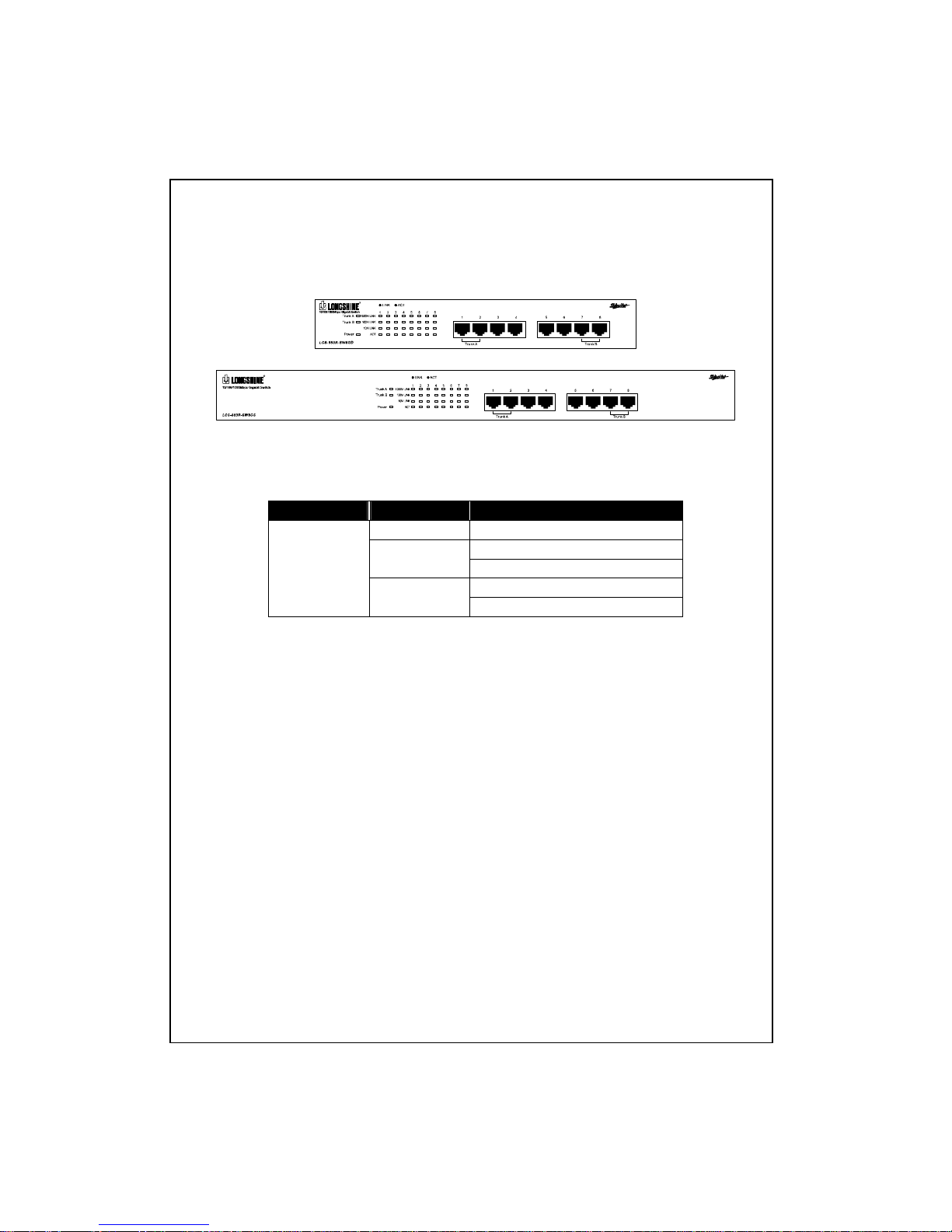
2.3 The Front Panel
The front panel of the switch is shown as below.
The auto-negotiation feature of the switch allows each port of the device
running at one of the following operation modes:
Port Speed Duplex Mode
1000 Mbps Full Duplex
Full Duplex 100 Mbps
Half Duplex
Full Duplex
Gigabit
10 Mbps
Half Duplex
Each port supports auto MDI/MDI-X capability that is the port could connect either
the PC or hub without any cable adjustment.
6

LEDs Definition
The rich diagnostic LEDs on the front-panel can provide the operating status of
individual port and whole system. The following table is a summary for LED s
definition.
Type LED Status Operation
Steady Green Power is on Power
Off Power is off
Steady Green Trunk mode enable
System
Trunk A/B
Off Disable
Steady Green Connected as 1000Mbps 1000M LINK
Off Not connected as 1000Mbps
Steady Green Connected as 100Mbps 100M LINK
Off Not connected as 100Mbps
Steady Green Connected as 10Mbps 10M LINK
Off Not connected as 10Mbps
Blinking Green There is traffic transverses the port
Port
ACT
Off No connection
2.3.1 System LEDs
System LED indicators are located on the front panel for showing the operating
status of the whole device.
2.3.1.1 Power LED
This indicator lights green when the switch is receiving power;
otherwise, it is off.
2.3.1.2 Trunk A/B LED
The switch supports 2 groups port-trunk; port-1 and port-2 belong to
“Trunk A”, port-7 and port-8 belong to “Trunk B”. This indicator lights
green when the relative group is functioning.
2.3.2 Port LEDs
Port LED indicators are located on the front panel for showing the operating
status of each port.
7
 Loading...