


PBX-PFX-SER Rev E
Service Manual
Models: 502, 752, 1002, 1302,
1501, 1701, and 2001
Up To 5:1 Turndown
WARNING |
This manual must only be used |
|||
|
by a qualified heating installer / |
|||
|
service technician. |
Read |
all |
|
|
instructions, including |
this |
||
|
manual and the Power-fin |
|||
|
Installation |
and |
Operation |
|
|
Manual, |
before |
installing. |
|
|
Perform steps in the order given. |
|||
|
Failure to comply could result in |
|||
|
severe personal injury, death, or |
|||
|
substantial property damage. |
|
||
Save this manual for future reference.
Service Manual
Contents
Contents . . . . . . . . . . . . . . . . . . . . . . . . . . . . . . . . . . . . . . . . . . . . . . . . . . . . . . . 2 Hazard definitions . . . . . . . . . . . . . . . . . . . . . . . . . . . . . . . . . . . . . . . . . . . . . . . . 2 Please read before proceeding . . . . . . . . . . . . . . . . . . . . . . . . . . . . . . . . . . . . . 3 What is in this manual? . . . . . . . . . . . . . . . . . . . . . . . . . . . . . . . . . . . . . . . . . . . 4 1. Service . . . . . . . . . . . . . . . . . . . . . . . . . . . . . . . . . . . . . . . . . . . . . . . . . . . . . . 5 2. Maintenance . . . . . . . . . . . . . . . . . . . . . . . . . . . . . . . . . . . . . . . . . . . . . . . . . . 22 3. Troubleshooting . . . . . . . . . . . . . . . . . . . . . . . . . . . . . . . . . . . . . . . . . . . . . . . 31
Troubleshooting Chart - No Display . . . . . . . . . . . . . . . . . . . . . . . . . . . . . . . . 32
Checking Temperature Sensors . . . . . . . . . . . . . . . . . . . . . . . . . . . . . . . . . . . 33
Troubleshooting Chart - Noisy System . . . . . . . . . . . . . . . . . . . . . . . . . . . . . 34
Troubleshooting Chart - Fault Messages . . . . . . . . . . . . . . . . . . . . . . . . . . . . 35
Revision Notes . . . . . . . . . . . . . . . . . . . . . . . . . . . . . . . . . . . . . . . . . . . Back Cover
Hazard definitions
The following defined terms are used throughout this manual to bring attention to the presence of hazards of various risk levels or to important information concerning the life of the product.
DANGER
WARNING
CAUTION
CAUTION
NOTICE
DANGER indicates an imminently hazardous situation which, if not avoided, will result in death or serious injury.
WARNING indicates a potentially hazardous situation which, if not avoided, could result in death or serious injury.
CAUTION indicates a potentially hazardous situation which, if not avoided, may result in minor or moderate injury.
CAUTION used without the safety alert symbol indicates a potentially hazardous situation which, if not avoided, may result in property damage.
NOTICE indicates special instructions on installation, operation, or maintenance that are important but not related to personal injury or property damage.
2

Service Manual
Please read before proceeding
WARNING
NOTICE
Installer – Read all instructions, including this manual and the Power-fin Installation and Operation Manual, before installing. Perform steps in the order given.
User – This manual is for use only by a qualified heating installer/service technician. Refer to the Power-fin User’s Information Manual for your reference.
Have this appliance serviced/inspected by a qualified service technician at least annually.
Failure to comply with the above could result in severe personal injury, death or substantial property damage.
When calling or writing about the appliance – Please have the appliance model and serial number from the appliance’s rating plate.
Consider piping and installation when determining appliance location (see the Power-fin Installation and Operation Manual).
Any claims for damage or shortage in shipment must be filed immediately against the transportation company by the consignee.
When servicing appliance –
•To avoid electric shock, disconnect electrical supply before performing maintenance.
•To avoid severe burns, allow appliance to cool before performing maintenance.
Appliance operation –
•Do not block flow of combustion or ventilation air to the appliance.
•Should overheating occur or gas supply fail to shut off, do not turn off or disconnect electrical supply to circulator. Instead, shut off the gas supply at a location external to the appliance.
•Do not use this appliance if any part has been under water. The possible damage to a flooded appliance can be extensive and present numerous safety hazards. Any appliance that has been under water must be replaced.
Appliance water –
•Thoroughly flush the system (without appliance connected) to remove sediment. The high-efficiency heat exchanger can be damaged by build-up or corrosion due to sediment.
•Do not use petroleum-based cleaning or sealing compounds in the appliance system. Gaskets and seals in the system may be damaged. This can result in substantial property damage.
•Do not use “homemade cures” or “appliance patent medicines”. Serious damage to the appliance, personnel, and/or property may result.
3

What is in this manual?
Service
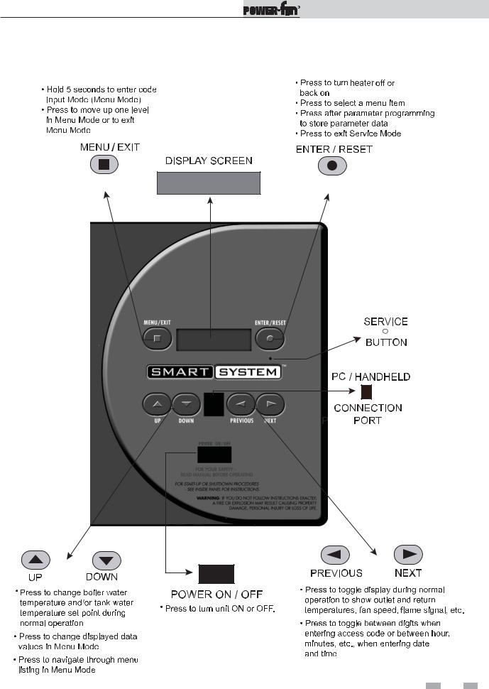
The Power-fin display
• Display panel readout, buttons and their functions
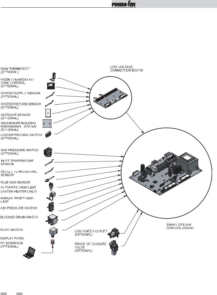
Control module inputs
• Control module inputs and options
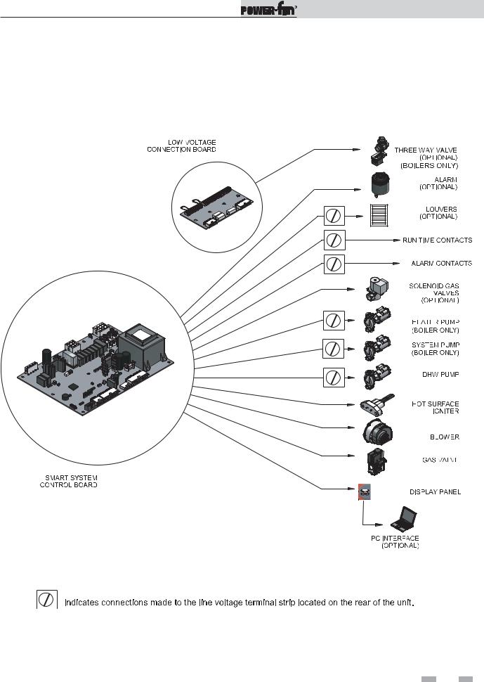
Control module outputs
• Control module outputs and options
General
•How the appliance operates
•How the control module operates
•Access modes -- user and installer
•Sequence of operation -- Domestic Hot Water (DHW)/space heating
Control panel menu access
•Accessing programming mode and locating menus (See separate guides covering the PC and pocket PC interfaces)
Control panel parameter access
• Accessing and changing parameters from the display panel
Quick start information -- parameter table
•An index of available adjustments and readouts, where to access them and where to find detailed information.
Power-fin operation
•A: General
•B: Temperature Setting
•C: Data Logging
•D: Functions
•E: DHW Settings
•F: Outdoor Air Reset Curve
•G: Anti-cycling
•H: Control Modes
•I: Cascade
•J: Building Management System (BMS)
•K: Circulation Pumps
•L: Service Notification
Service Manual
Maintenance
•Service and maintenance schedules
•Address reported problems
•Inspect appliance area and appliance interior
•Clean condensate trap
•Check all piping for leaks
•Flue vent system and air piping
•Check water system
•Check expansion tank
•Check control settings
•Check igniter
•Check all appliance wiring
•Check flue gas passageways
•Flame inspection
•Inspect and clean burner
•General maintenance
•Checking manifold gas pressure
•Combustion analysis procedure
•Gas valve adjustment procedure
•Cleaning heat exchanger
•Review with owner
Troubleshooting
•Troubleshooting table - No display
•Checking temperature sensors
•Troubleshooting table - Noisy system
•Troubleshooting table - Fault messages displayed on Operator Interface
4
Service Manual
1Service
The Power-fin display
5
Service Manual
1Service
Control inputs
6
Service Manual
1Service (continued)
Control outputs
7

Service Manual
1Service
General Operation
How the appliance operates
The Power-fin uses a copper-finned tube heat exchanger to transfer heat from the flue products to the water. An electronic control module monitors various inputs to initiate a call for heat. The blower provides both primary and secondary air to the burner and forces the flue products out of the combustion chamber and into the vent system. The control module regulates the blower speed (on B9 and M9 models) to control the firing rate of the appliance. The modulating gas valve monitors the amount of combustion air being pulled into the blower and regulates the amount of gas supplied, which then mixes with the combustion air and is supplied to the burner.
How the control module operates
The Power-fin control module receives input from appliance sensors. The control module activates and controls the blower and gas valve to regulate heat input and switches heater, DHW and system pumps on and off as needed. The user/installer programs the module to meet system needs by adjusting control parameters. These parameters set operating temperatures and heater operating modes. Appliance operation can be based on heater outlet water temperature, heater return water temperature, system supply temperature, system return temperature or tank temperature, depending on the parameter setting.
Sequence of operation
Table 1A shows control module normal sequences of operation for space heating and DHW operation. The combined operation sequence is for a typical application, programmed to provide DHW priority.
Access modes
User
The user can adjust space heating set point using the UP and DOWN buttons at any time during normal operation. By entering the USER code (0704), the user can also change temperature units, time and date, and night setback settings. In user mode, the following parameters can be viewed but not changed: Heater outlet water temperature in DHW mode; heater model number; software version; total operating hours, and total cycles.
Installer
Most parameters are available only to the installer, accessible only by entering the installer access code (5309).
Saving parameters
To save parameters and exit programming:
Press the ENTER/RESET button, then the MENU/EXIT button 3 times.
To keep parameter settings only for a current operating cycle:
Press the MENU/EXIT button 3 times after making all desired parameter changes.
To enter a parameter and continue programming:
Press the MENU/EXIT button 1 time to return to the parameter listings; press again to return to the menu listings. Remember to press the ENTER/RESET button when finished programming in order to save the changes made.
8

Service Manual
1Service (continued)
Sequence of operation
Table 1A_Sequence of Operation - Space Heating and DHW
OPERATION |
DISPLAY |
|
|
1. The manual reset high limit must be closed before any |
HTR: Standby |
action will take place. |
OUT: 123.8F(129) |
|
|
2. Upon a call for heat the control turns on the appropriate |
HTR: Standby |
pumps (system and boiler pumps for space heating; DHW |
|
pump for DHW call). The flow switch and low water cutoff (if |
OUT: 123.8F(129) |
equipped) must close. |
|
|
|
3. • If the unit is equipped with a proof of closure valve, the |
|
proof of closure switch must be closed. The proof of |
|
closure valve is then energized. The gas pressure |
|
switch(es) (if equipped) must close. |
HTR: Standby |
• If the contact for the louvers is closed, the louver proving, |
|
blocked drain switch, and auto reset high limit (water |
OUT: 123.8F(129) |
heater only) inputs must close. |
|
• If the air pressure switch is open, the prepurge cycle then |
|
begins by starting the combustion blower. Once started, |
|
the air pressure switch must close. |
|
|
|
4. After the 10 second prepurge, the blower slows down and |
HTR: PREPURGE |
the hot surface igniter (HSI) is energized. The HSI is heated |
|
for at least 15 seconds. |
OUT: 123.9F(129) |
5. Once the HSI is hot, the trial for ignition begins with the |
HTR: IGNITION |
opening of the gas valve. |
OUT: 123.9F(129) |
|
|
6. If the SMART SYSTEM control does not sense flame within |
HTR: POSTPURGE, PREPURGE |
7 seconds of the opening of the gas valve, then it will lock |
OUT: 123.9F(129) |
out. |
|
|
|
7. If the SMART SYSTEM control senses flame within 7 |
|
seconds, it will fire the burner to maintain the set point. On |
HTR: SH 20% RATE |
B9 and M9 models, the firing rate will modulate as required |
|
to hold the actual temperature at the set point. If the boiler |
|
lights due to a space heating call for heat, and the ramp |
OUT: 124.8F(129) |
delay function is active (default is disabled), the modulation |
|
will be held to a series of increasing limits after the burner |
|
has lit. |
|
|
|
8. If the space heating call for heat is active, and the DHW |
|
thermostat closes, the control will turn on the DHW pump, |
HTR: DHW 85% RATE |
wait 2 seconds, and then turn off the boiler pump. This will |
|
divert the hot water away from the heating zone(s) and send |
OUT: 177.8(180) |
it to the DHW tank instead. The control will then modulate |
|
(B9 and M9 models only) to maintain the outlet temperature |
|
to the DHW boiler set point. |
|
|
|
9

Service Manual
1Service
Sequence of operation
Table 1A_(continued from previous page) Sequence of Operation - Space Heating and DHW
OPERATION |
DISPLAY |
|
|
9. If the DHW thermostat remains on for more than |
|
30 minutes, and the space heating call for heat is also on, |
|
then the control will turn on the boiler pump, turn off the |
HTR: SH 41% RATE |
DHW pump after 2 seconds, and resume firing based on the |
|
space heating set point. As long as both the space heating |
OUT: 123.0F(129) |
and DHW calls for heat remain active, the control will switch |
|
back and forth between the two modes until one of them is |
|
satisfied. |
|
|
|
10. Once both calls for heat are satisfied, the control will turn |
|
off the burner. The blower will remain on for the |
HTR: POSTPURGE |
30 second postpurge cycle. Any pumps that are running |
|
will continue to run for their respective pump delay times, |
OUT: 127.4F(129) |
then turn off. |
|
|
|
11. Boiler pump off, system pump continues its delay if |
HTR: Standby |
longer. |
OUT: 124.7F(129) |
|
|
12. System pump off. |
HTR: Standby |
|
OUT: 122.9F(129) |
 10
10 

Service Manual
1Service (continued)
Display panel menu access
Table 1B_Use this procedure to access menus from the display panel
Note: Not all menu listings shown above are available on water heaters.
 11
11 
Service Manual
1Service
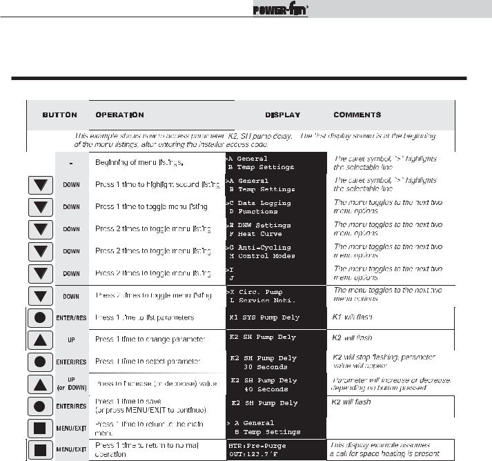
Display panel parameter access
Table 1C_This is a typical example of accessing a parameter, shown for parameter K2, SH pump delay
Cascade |
BMS |
 12
12 

Service Manual
1Service (continued)
Parameter table
Table 1D_This table lists SMART SYSTEM control module parameters and where to access them
|
|
MENU |
SUB ITEM |
DESCRIPTION |
SEE |
USER ACCESS |
INSTALLER ACCESS |
|
|||
|
|
PAGE |
DISPLAY |
MODIFY |
DISPLAY |
MODIFY |
|
||||
|
|
|
|
|
|
||||||
|
|
|
|
|
|
|
|
|
|
|
|
GENERAL |
|
|
1 |
Heater Model |
15 |
Yes |
No |
Yes |
No |
|
|
|
|
|
|
|
|
|
|
|
|
|
|
|
|
2 |
User Code |
15 |
Yes |
Yes |
Yes |
Yes |
|
||
|
|
|
|
||||||||
|
|
|
|
|
|
|
|
|
|
|
|
|
|
|
3 |
Date and Time |
15 |
Yes |
Yes |
Yes |
Yes |
|
|
|
|
|
|
|
|
|
|
|
|
|
|
|
|
A |
4 |
Software Version |
15 |
Yes |
No |
Yes |
No |
|
|
|
|
|
|
|
|
|
|
|
|
|
|
|
|
|
5 |
Temperature Units |
15 |
Yes |
Yes |
Yes |
Yes |
|
|
|
|
|
|
|
|
|
|
|
|
|
|
|
|
|
6 |
Night Setback Temperature |
15 |
Yes |
Yes |
Yes |
Yes |
|
|
|
|
|
|
|
|
|
|
|
|
|
|
|
|
|
7 |
Night Setback Times |
15 |
Yes |
Yes |
Yes |
Yes |
|
|
|
|
|
|
|
|
|
|
|
|
|
|
|
|
|
|
|
|
|
|
|
|
|
|
TEMPERATURESETTING |
|
|
1 |
SH Set Point User |
15 |
Yes |
Yes |
Yes |
Yes |
||
|
|
|
|||||||||
|
|
|
|
|
|
|
|
|
|
|
|
|
|
|
2 |
SH Minimum Set Point |
15 |
No |
No |
Yes |
Yes |
||
|
|
B |
|
|
|
|
|
|
|
|
|
|
|
3 |
SH Maximum Set Point |
15 |
No |
No |
Yes |
Yes |
|||
|
|
|
4 |
SH Offset |
15 |
No |
No |
Yes |
Yes |
||
|
|
|
|
|
|
|
|
|
|
|
|
|
|
|
5 |
SH Differential |
15 |
No |
No |
Yes |
Yes |
||
|
|
|
|
|
|
|
|
|
|
|
|
|
|
|
|
|
|
|
|
|
|
|
|
DATALOGGING |
|
|
|
|
|
|
|
|
|
|
|
|
|
1 |
Hours Running SH |
16 |
Yes |
No |
Yes |
No |
|
|
|
|
|
|
|
|
|
|
|
|
|
|
|
|
|
C |
2 |
Hours Running DHW |
16 |
Yes |
No |
Yes |
No |
|
|
|
|
|
|
|
|
|
|
|
|
|
|
|
|
3 |
Ignition Attempts |
16 |
Yes |
No |
Yes |
No |
|
|
|
|
|
|
|
||||||||
|
|
|
|
|
|
|
|
|
|
|
|
|
|
|
4 |
Show Last 10 Errors |
16 |
Yes |
No |
Yes |
No |
|
|
|
|
|
|
|
|
|
|
|
|
|
|
|
|
|
|
|
|
|
|
|
|
|
|
|
|
|
|
|
|
|
|
|
|
|
|
FUNCTIONS |
|
|
|
|
|
|
|
|
|
|
|
|
|
1 |
Service Mode Delay |
16 |
No |
No |
Yes |
Yes |
|
|
|
|
|
|
|
||||||||
|
|
D |
|
|
|
|
|
|
|
|
|
|
|
2 |
Reset Last 10 Errors |
16 |
No |
No |
Yes |
Yes |
|
|
|
|
|
|
|
||||||||
|
|
|
|
|
|
|
|
|
|
|
|
|
|
|
|
|
|
|
|
|
|
|
|
|
|
|
|
|
|
|
|
|
|
|
|
DHW SETTINGS |
|
|
|
|
|
|
|
|
|
|
|
|
|
1 |
DHW Tank Set Point |
16 |
Yes |
Yes |
Yes |
Yes |
|
||
|
|
|
|
||||||||
|
|
E |
|
|
|
|
|
|
|
|
|
|
|
2 |
DHW Boiler Set Point |
16 |
Yes |
Yes |
Yes |
Yes |
|
||
|
|
|
|
|
|
|
|
|
|
|
|
|
|
|
3 |
SH/DHW Switching Time |
16 |
Yes |
Yes |
Yes |
Yes |
|
|
|
|
|
|
|
|
|
|
|
|
|
|
|
|
|
|
|
|
|
|
|
|
|
|
|
|
|
|
|
|
|
|
|
|
|
|
|
|
|
|
|
|
|
|
|
|
|
|
|
|
|
1 |
Minimum Air Temperature |
16 |
No |
No |
Yes |
Yes |
|
|
RESET |
|
|
|
|
|
|
|
|
|
|
|
|
|
2 |
Maximum Air Temperature |
16 |
No |
No |
Yes |
Yes |
|
|
|
|
|
|
|
|
|
|
|
|
|
|
|
|
|
3 |
Maximum SH Set Point |
17 |
No |
No |
Yes |
Yes |
|
|
|
|
|
|
|
|
|
|
|
|
|
|
|
AIR |
|
|
4 |
Minimum SH Set Point |
17 |
No |
No |
Yes |
Yes |
|
|
|
|
|
|
|
|
|
|
|
|
|
|
|
F |
5 |
Outdoor Air Shutdown |
17 |
Yes |
Yes |
Yes |
Yes |
|
|
|
|
|
|
|||||||||
OUTDOOR |
|
|
|
|
|
|
|
|
|
|
|
|
|
6 |
Outdoor Air Shutdown |
17 |
Yes |
Yes |
Yes |
Yes |
|
|
|
|
|
|
|
|
|||||||
|
|
|
Differential |
|
|||||||
|
|
|
|
|
|
|
|
|
|
|
|
|
|
|
7 |
Shift Reset Curve |
17 |
No |
No |
Yes |
Yes |
|
|
|
|
|
|
|
|
|
|
|
|
|
|
|
|
|
8 |
Boost Temperature |
18 |
Yes |
Yes |
Yes |
Yes |
|
|
|
|
|
|
|
|
|
|
|
|
|
|
|
|
|
9 |
Boost Time |
18 |
Yes |
Yes |
Yes |
Yes |
|
|
|
|
|
|
|
|
|
|
|
|
|
|
|
|
|
|
|
|
|
|
|
|
|
|
 13
13 

Service Manual
1Service
Parameter table (continued)
Table 1D_(continued from previous page) This table lists SMART SYSTEM control module parameters and where to access them
CYCLING- |
|
MENU |
|
DESCRIPTION |
SEE |
USER ACCESS |
INSTALLER ACCESS |
||
|
2 |
18 |
No |
No |
Yes |
Yes |
|||
|
|
SUB ITEM |
PAGE |
DISPLAY |
MODIFY |
DISPLAY |
MODIFY |
||
|
|
|
1 |
Anti-cycling Time |
18 |
No |
No |
Yes |
Yes |
|
|
|
|
|
|
|
|
|
|
|
|
|
|
Inlet Temperature Differential for |
|
|
|
|
|
ANTI |
|
G |
|
Ending Anti-Cycling |
|
|
|
|
|
|
|
3 |
Ramp Delay On/Off |
18 |
No |
No |
Yes |
Yes |
|
|
|
|
|||||||
|
|
|
|
|
|
|
|
|
|
|
|
|
4 |
Ramp Delay Settings (boiler only) |
18 |
No |
No |
Yes |
Yes |
|
|
|
|
|
|
|
|
|
|
|
|
|
|
|
|
|
|
|
|
CONTROL MODES |
|
|
1 |
SH Controlling Sensor |
19 |
No |
No |
Yes |
Yes |
|
|
(Outlet/System, Inlet) |
|||||||
|
|
|
|
|
|
|
|
||
|
|
2 |
Enable Input |
19 |
No |
No |
Yes |
Yes |
|
|
|
|
|||||||
|
|
H |
|
|
|
|
|
|
|
|
|
3 |
0-10V Building Management Input |
19 |
No |
No |
Yes |
Yes |
|
|
|
|
|||||||
|
|
|
|
|
|
|
|
|
|
|
|
|
4 |
Cascade |
19 |
No |
No |
Yes |
Yes |
|
|
|
|
|
|
|
|
|
|
|
|
|
|
|
|
|
|
|
|
|
|
|
|
|
|
|
|
|
|
CASCADE |
|
|
1 |
Boiler Cascade Address |
19 |
No |
No |
Yes |
Yes |
|
|
|
|
|
|
|
|
|
|
|
|
2 |
Max. Cascade Set Point |
20 |
No |
No |
Yes |
Yes |
|
|
|
|
|||||||
|
|
I |
|
|
|
|
|
|
|
|
|
3 |
Cascade Offset |
20 |
No |
No |
Yes |
Yes |
|
|
|
|
|||||||
|
|
|
|
|
|
|
|
|
|
|
|
|
4 |
Cascade Off-On Differential |
20 |
No |
No |
Yes |
Yes |
|
|
|
|
|
|
|
|
|
|
|
|
|
|
|
|
|
|
|
|
BUILDING MANAGEMENT
CIRCULATION
SERVICE
|
|
|
|
|
|
|
|
|
|
|
|
|
|
|
1 |
BMS Type |
20 |
No |
No |
Yes |
Yes |
|
|
|
|
|
|
|
|
|
|
|
|
|
|
|
|
|
2 |
Voltage at Minimum |
20 |
No |
No |
Yes |
Yes |
|
|
(BMS) |
|
|
|
|
|
|
|
|
|
|
|
|
|
3 |
Voltage at Maximum |
20 |
No |
No |
Yes |
Yes |
|
||
|
|
|
|
||||||||
|
|
|
|
|
|
|
|
|
|
|
|
|
|
|
4 |
Minimum Power |
20 |
No |
No |
Yes |
Yes |
|
|
SYSTEM |
|
J |
|
|
|
|
|
|
|
|
|
|
5 |
Maximum Power |
20 |
No |
No |
Yes |
Yes |
|
|||
|
|
|
|||||||||
|
|
|
6 |
Minimum Set Point |
20 |
No |
No |
Yes |
Yes |
|
|
|
|
|
|
|
|
|
|
|
|
|
|
|
|
|
7 |
Maximum Set Point |
21 |
No |
No |
Yes |
Yes |
|
|
|
|
|
|
|
|
|
|
|
|
|
|
|
|
|
8 |
Voltage at Start |
21 |
No |
No |
Yes |
Yes |
|
|
|
|
|
|
|
|
|
|
|
|
|
|
|
|
|
9 |
Voltage at Stop |
21 |
No |
No |
Yes |
Yes |
|
|
PUMPS |
|
|
|
|
|
|
|
|
|
|
|
|
|
|
|
|
|
|
|
|
|
||
|
|
|
|
|
|
|
|
|
|
||
|
|
1 |
System Pump Delay |
21 |
No |
No |
Yes |
Yes |
|||
|
K |
|
|
|
|
|
|
|
|
||
2 |
SH Pump Delay |
21 |
No |
No |
Yes |
Yes |
|||||
|
|
||||||||||
|
|
|
|
|
|
|
|
|
|
|
|
|
|
|
3 |
DHW Pump Delay |
21 |
No |
No |
Yes |
Yes |
||
NOTIFICATION |
|
|
|
|
|
|
|
|
|
|
|
|
|
|
|
|
|
|
|
|
|
||
|
|
|
|
|
|
|
|
|
|
||
|
|
1 |
Service Notification in Months |
21 |
No |
No |
Yes |
Yes |
|
||
|
|
|
|
|
|
|
|
|
|
||
|
5 |
Accept PPlug |
21 |
No |
No |
Yes |
Yes |
|
|||
|
|
|
2 |
Service Notification Running Hours |
21 |
No |
No |
Yes |
Yes |
|
|
|
|
L |
3 |
Service Notification Boiler Cycles |
21 |
No |
No |
Yes |
Yes |
|
|
|
|
|
4 |
Reset Service Notification Counter |
21 |
No |
No |
Yes |
Yes |
|
|
|
|
|
|
|
|
|
|
|
|
|
|
|
|
|
|
|
|
|
|
|
|
|
|
|
|
|
|
|
|
|
|
|
|
|
|
 14
14 
 Loading...