

Page 1

LNC-M600i
M
M
aii
a
ntt
n
e
e
n
a
n
c
n
a
n
Leading Numerical Controller
e
c
e
2009/10 Ver:V04.00.000(4408210076)
M
M
a
a
n
n
u
u
all
a
LNC Technology Co., Ltd.
Page 2

Page 3

LNC-M600i
Table of Contents
Table of Contents
1 SPECIFICATION ........................................................................................................ 1
1.1 Normal Specification & Option Specification ..................................................................................1
2 Software Maintenance.............................................................................................. 2
2.1 LNC-M600i Installation Description ................................................................................................2
2.1.1 [O.S UTILITY] ......................................................................................................................2
2.1.2 [LNC_M600 INSTALL DISK]................................................................................................3
2.1.3 Font Disk.............................................................................................................................. 5
2.2 System update................................................................................................................................ 6
2.3 System Direction Description .......................................................................................................10
2.3.1 [OS.UTILTIY] Results ........................................................................................................10
2.3.2 [LNC_M600 INSTALL DISK] Results................................................................................. 10
3 Hardware Maintenance............................................................................................11
3.1 LNC-600i Product Display ............................................................................................................ 11
3.1.1 Specification.......................................................................................................................12
3.2 ELCLCD-2601 system connection and description...................................................................... 17
3.3 OT/EMG PIN.................................................................................................................................27
3.4 Hardware Module Description ......................................................................................................32
3.4.1 I/O Module .........................................................................................................................32
3.4.2 I/O card SIO 1520 definition ..............................................................................................34
3.4.3 I/O SIO 1540 DEFINITION ................................................................................................41
3.4.4 MDIOP8500 OP DESCRIPTION ....................................................................................... 51
4 PLC Maintenance -- C,S Bits and Register......................................................... 62
4.1 C Bits Definition ............................................................................................................................ 62
4.2 S Bits Definition ............................................................................................................................65
4.3 Register Definition ........................................................................................................................67
4.4 C Bits Description ......................................................................................................................... 68
4.5 S Bits Desctiption..........................................................................................................................80
4.6 Register Desctiption .....................................................................................................................89
4.7 PLC Window Function ..................................................................................................................95
4.8 PLC Initial Setting Description(PLCIO.CFG) ...........................................................................99
5 Parameter .............................................................................................................. 101
5.1 Parameter List ............................................................................................................................102
LNC Technology Co., Ltd. I
Page 4

LNC-M600i
Table of Contents
5.2 Servo Parameter ........................................................................................................................ 117
5.3 Machine Parameter ....................................................................................................................130
5.4 Spindle Parameter......................................................................................................................132
5.5 MPG Parameter..........................................................................................................................151
5.6 Compensation Parameter...........................................................................................................152
5.7 Zero Return parameter ...............................................................................................................159
5.8 Operation Parameter ..................................................................................................................172
6 SYSTEM ALARM and WARNING ......................................................................... 199
6.1 OP OPERATION RELATED ALARM .......................................................................................... 200
6.2 OP OPERATION RELATED WARNING..................................................................................... 203
6.3 INT INTERPRETATION RELATED ALARM ...............................................................................204
6.4 MOT MOTION RELATED ALARM..............................................................................................212
6.5 MOT RELATING ALARM............................................................................................................225
7 Machine Adjustment............................................................................................. 226
7.1 Milling Rigid Tapping Commanding ............................................................................................226
7.2 Laser Compensation Procedure.................................................................................................231
7.3 Double Ball Bar Measure – Backlash or Circular Spike .............................................................234
7.4 Spindle Positioning Tuning .........................................................................................................236
8 Dimension and Installation .................................................................................. 238
8.1 Dimension...................................................................................................................................238
8.1.1 ELCLCD-2601 Dimension ...............................................................................................238
8.1.2 MDIOP-8500 Dimension.................................................................................................. 238
8.1.3 MDIOP-8501 Dimension.................................................................................................. 239
8.1.4 MDIOP-8510 Dimension.................................................................................................. 239
8.2 Dimension...................................................................................................................................240
8.2.1 ELCLCD-2601 Dimension ...............................................................................................240
8.2.2 MDIOP-8500 Dimension.................................................................................................. 240
8.2.3 MDIOP-8501 Dimension.................................................................................................. 241
8.2.4 MDIOP-8510 Dimension.................................................................................................. 241
8.3 TRF-9500 Dimension and installation ........................................................................................242
APPENDIX A PARAMETER ADJUSTMENT EXAMPLE .............................................. 243
A1 Parameter Adjustment of V Command Control Method ................................................................243
A2 Parameter Adjustment when Encoder is installed besides Ball Screw..........................................246
A3 Parameter Adjustment when using Linear Scale Control Method .................................................248
Appendix B:Servo Connection Example ................................................................. 251
II
LNC Technology Co., Ltd.
Page 5

LNC-M600i
Table of Contents
B1 Yaskawa Servo Connection Example ............................................................................................251
B2 Panasonic Servo Connection Example .........................................................................................257
B3 Mitsubishi Servo Example..............................................................................................................260
B4 TOSHIBA converter........................................................................................................................265
Appendix C:3 In 1 MPG Connection Example......................................................... 277
Appendix D RS232 Connection Description.............................................................. 279
Appendix E Internet Setting Description ................................................................... 281
Appendix F Wiring Diagram........................................................................................ 347
A-System Configuration ......................................................................................................................347
B-Main Power Cable............................................................................................................................362
C-Control Loop Wiring Diagram ..........................................................................................................366
E-ON/OFF ...........................................................................................................................................368
F-Spindle Terminal Interface................................................................................................................ 369
I-INPUT Wiring ....................................................................................................................................371
O-OUTPUT Wiring...............................................................................................................................373
P-Servo Main Power............................................................................................................................375
T- I/O LIst.............................................................................................................................................381
LNC Technology Co., Ltd. III
Page 6

Page 7

LNC-M600i
SPECIFICATION
1 SPECIFICATION
LNC-M600i Series is a standard DOS-Based controller and also an integrated numerical controller product
which is designed by LNC Technology. Its stability in quality is best suitable for applications of middle
complexity, such as lathe, milling, grinding and all other kinds of industrial and automatically tools.
The following introduces the functional and structure specification of LNC-M600i series controller.
1.1 Normal Specification & Option Specification
Normal Specification
z Normal G/M Code Operating
z Background Editing
z MACRO Program Function
z External/Internal Program Transmitting Function for DNC
z Multiple Language Selection (English, Traditional/Simplify Chinese)
z Picture Simulation Display
z Soft Interface Extension
z Hardware Self-Diagnostic Display
z Additional back-up of Installation floppy disk
z PLC Ladder Diagram Display
z Internet Function
Option Specification
z CAD/CAM
LNC Technology Co., Ltd. 1
Page 8

LNC-M600i
Software Maintenance
2 Software Maintenance
2.1 LNC-M600i Installation Description
This system has 3 installation diskettes wich are [O.S UTILITY], [LNC_M600i INSTALL DISK], Text Font Disk
and also three anti-virus program diskettes, details are as below:
2.1.1 [O.S UTILITY]
Insert [O.S UTILITY] disk to floppy(A:) or run R.BAT, it shows as below:
WELCOME TO INSTALL LNC SERIES
THIS WILL GUIDE YOU TO CREATE AN
PLATFORM FOR LNC .APP AND UTILITIES.
--------------VER 2.5---------------
1.QUICK MAKE AN BOOTABLE H.D(C)
2.INSTALL PLC UTILITIES
3.INSTALL NETWORK UTILITIES
4.VIRUS SCAN
5.QUIT
CHOISE AN OPTION[1,2,3,4,5]?
z QUICK MAKE AN BOOTABLE H.D(C)
This will install OS to your IPC and make it bootable. Here is the step:
1. Prepare a formatted CF card.
2. Set the boot sequence of IPC to A: first
3. Insert [O.S UTILITY] disk to A:
4. RESET and boot with A:
5. Run this option
6. After all have done, reboot again and change boot sequence of IPC to C ONLY.
z INSTALL PLC UTILITIES
This will install PLC utilities to your IPC(OS required), but you need to install Operation System firstly
and proceed this software. After pressing install button, system will show if you are sure of it, then press
「Y」.
2
LNC Technology Co., Ltd.
Page 9

z INSTALL NETWORK UTILITIES
This will install network utilities to your IPC(OS required).
z VIRUS SCAN
To scan if the system has virus(OS and scan program required).
z QUIT
To quit installation.
2.1.2 [LNC_M600 INSTALL DISK]
Execute G.BAT of install disk, the screen will show as below:
====================================
LNC-M600i
Software Maintenance
WELCME TO INSTALL LNC-M600 SERIES
====================================
Please read the belows NOTICE first
before INSTALL task.
[1]Installing..below tasks are no
prompting!
a.The previous File/Directory that
named "*.BAK" will be killed!
b.The exist File/Directory that c-
onflict with SETUP will be rena-
med as "*.bak"!
LNC Technology Co., Ltd. 3
Page 10

LNC-M600i
Software Maintenance
After press any key:
=====================================
LNC-M600 INSTALL UTILITY V1.20
Copyright (C) POU CHEN 2002 05/07/2001
=====================================
1.Install
2.Maintain
3.Quit and Restart
Choice an Option[1,2,3]?
z Install
For first time full install or hard disk reconstraction. LNC-M600i SERIES has been installed in the disk
before selling. This selection is useless under normal usage unless the disk has been formated again
z Maintain
Maintenance selection, there are 3 items below:
1.PCscan
Virus checking
2.DISK doctor
Disk diagnostic and errer-fix
3.DEFRAG
Disk access performance enhancement
4
0.Quit
LNC Technology Co., Ltd.
Page 11

(1) PCscan:to scan if there are virus in the disk or not.
(2) DISK Doctor:to scan the disk is broken or not.
(3) DEFRAG:disk defragment.
z Quit
To quit install program and return to DOS.
2.1.3 Font Disk
To install fonts, execute G.BAT of install disk.
LNC-M600i
Software Maintenance
LNC Technology Co., Ltd. 5
Page 12
LNC-M600i
Software Maintenance
2.2 System update
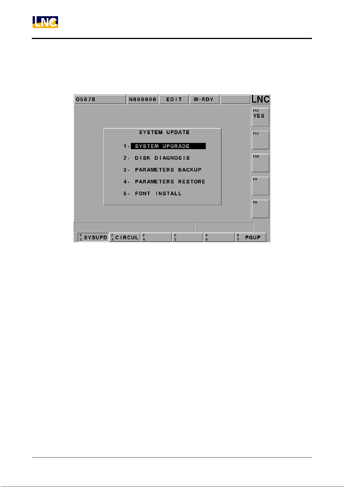
This function can only be executed under imcomplete preparation, press EMG-STOP and press system
update, below picture will be shown on the screen, users can choose each item to continue.
Figure 2.2-1 System Update Main Page
6
LNC Technology Co., Ltd.
Page 13
LNC-M600i
Software Maintenance
z System update
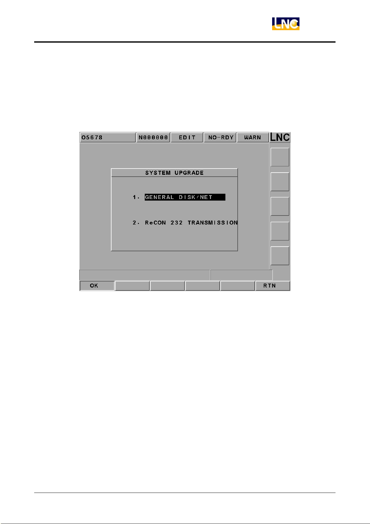
This function offers two ways for update: general disk/RS232 transmission. Please install LNC
Technology Co., Ltd. latest version software if choosing this function. Pressing【YES】, the installation
screen will occur. There is installation program instruction during installation so you only need to follow
the instruction to upgrade the system.
Figure 2.2-2 System Upgrade
At the system upgrade file,move cursor to the line and press【OK】
LNC Technology Co., Ltd. 7
Page 14
LNC-M600i
Software Maintenance
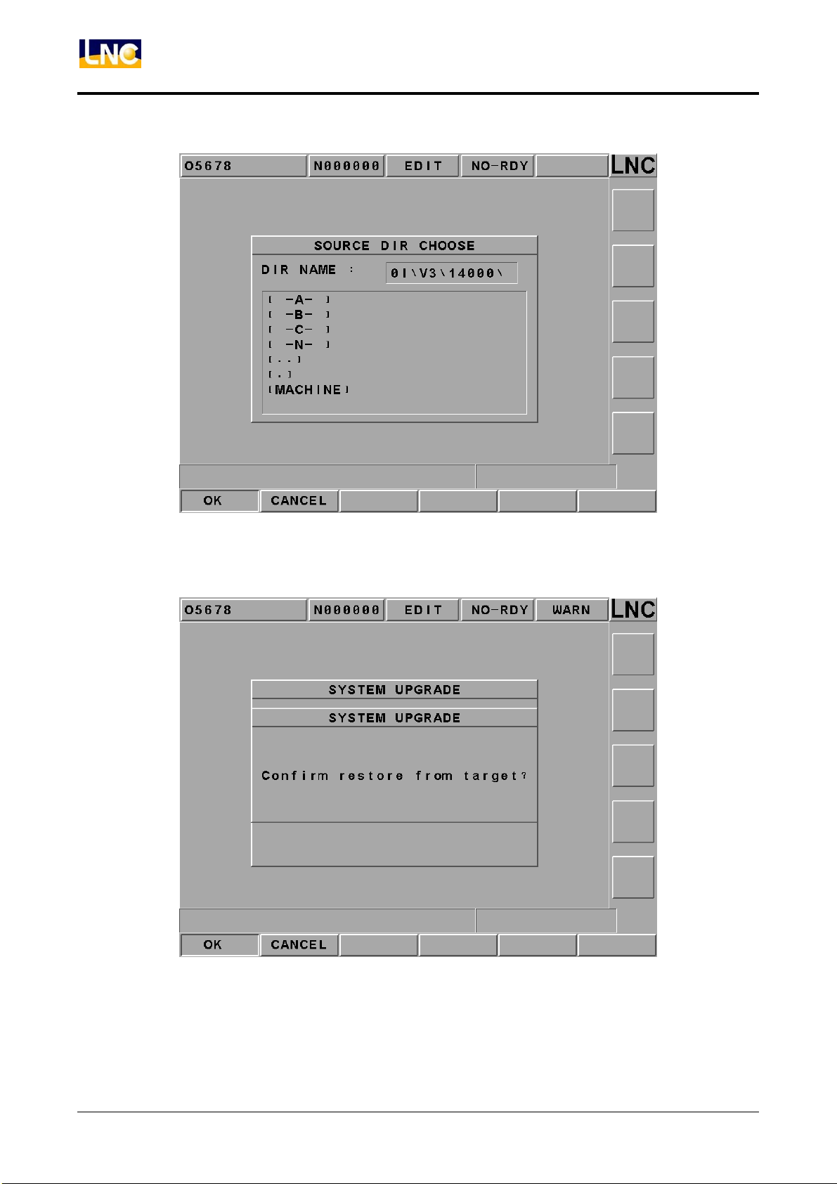
System will double confirm if you want to do upgrade, make sure if you really want to do upgrade and
press【OK】
Then system will turn to DOS page as below to show current version and update version, press【Y】and
system will process upgrade automatically.
8
LNC Technology Co., Ltd.
Page 15
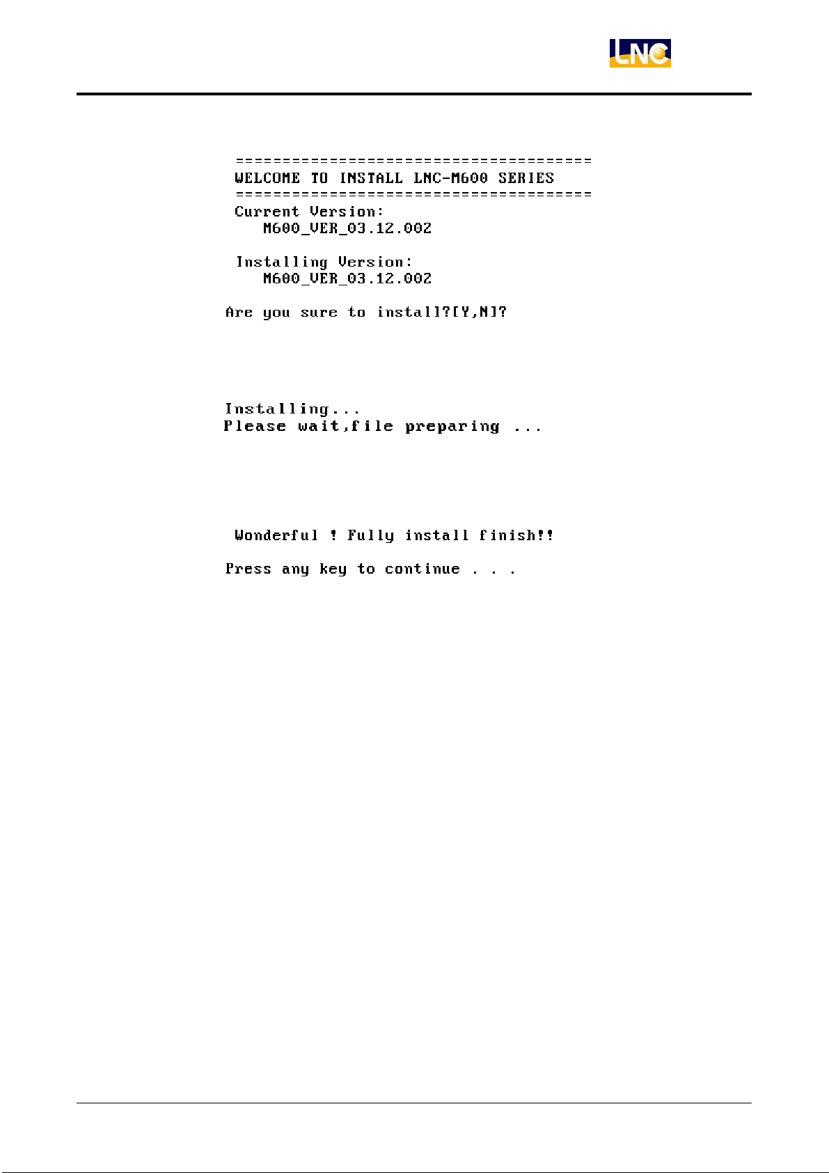
Please wait, file preparing.
LNC-M600i
Software Maintenance
System upgrade is completed, please press any key to reboot and you can use new version software
later.
LNC Technology Co., Ltd. 9
Page 16
LNC-M600i
Software Maintenance
2.3 System Direction Description
Users will find the following files in the system hardware after running LNC-M600i series installation program.
2.3.1 [OS.UTILTIY] Results
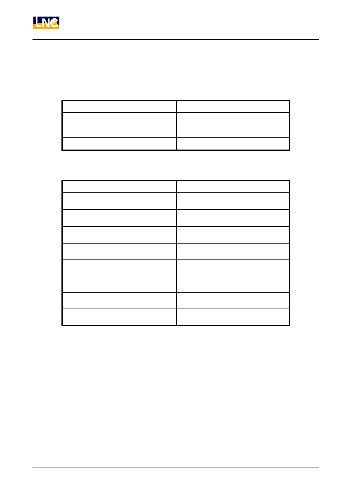
Name Files
C:\DOS\
C:\ANTIVIR\
C:\MLC:\MLC\
2.3.2 [LNC_M600 INSTALL DISK] Results
Name Files
C:\LNCMILL.BAK
C:\LNCMILL.B2
C:\LNCMILL\EXE
C:\LNCMILL\RESOURCE
C:\LNCMILL\MACHINE
C:\LNCMILL\MACRO
C:\LNCMILL\NCFILES
C:\LNCMILL\CAMPRJ
IBM PC_DOS 2000 files(partially)
Anti-Virus
Ladder editor
Backup of LNCMILL directory(last edition)
Backup of LNCMILL directory (recently
edition)
System files
Environment relative data files
(refer to DIR.DOC)
LADDER and system files
Canned cycle macro for Standard miller
(user’s NC files should not be here)
User’s NC files
(file name must be O0000~O8999)
CAM project files
(extended file name is *.DAT)
10
LNC Technology Co., Ltd.
Page 17
3 Hardware Maintenance
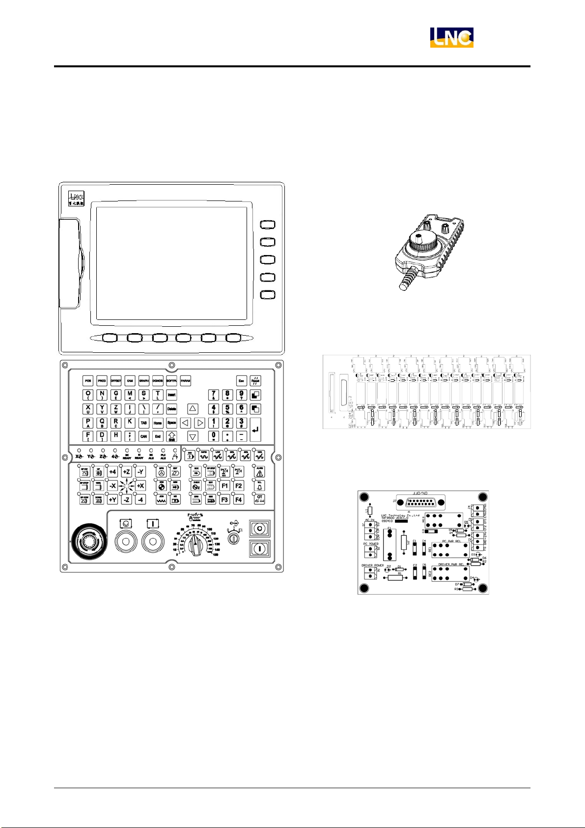
3.1 LNC-600i Product Display
ELCLCD-2601
LNC-M600i
Hardware Maintenance
MPG
MDIOP-85 series
REL-2840
TRF-9500
LNC Technology Co., Ltd. 11
Page 18
LNC-M600i
Hardware Maintenance
3.1.1 Specification
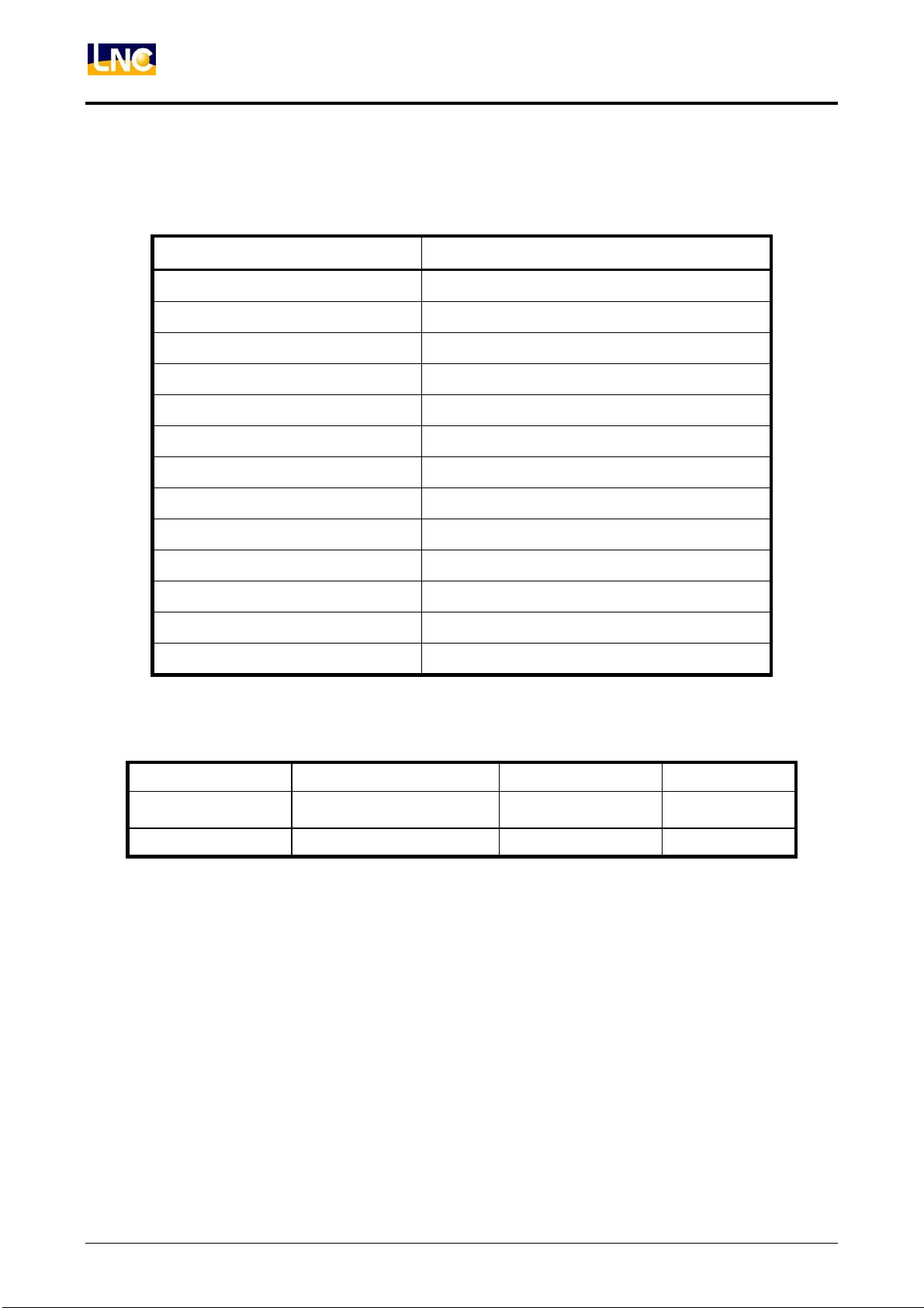
System hardware specification:
ELCLCD-2601 Specification
Monitor 10.4” full color TFT montior
SDRAM 64M bytes or above
Single CF Card 64M bytes or above
PC Motherboard Industrial PC board
Remote I/O Max 128 Input/128 Output
USER I/O 20Input/16 Output
Servo System Offer position loop/Speed loop control (Optional)
DNC RS232 19200 Baud Rate
Operation Panel Standard Lathe OP
MPG Interface 3 in 1 MPG
Control Axes 3 axes
Spindle Numbers 1 axis
Power AC 110V/230V 50Hz/60Hz
System Power Demand:
Power Category Specification Usage Note
System Power AC110V/230V 50Hz/60Hz For System
External Power(24V) DC24V/(4A UP)
Fixed at system
back side
For external IO
12
LNC Technology Co., Ltd.
Page 19
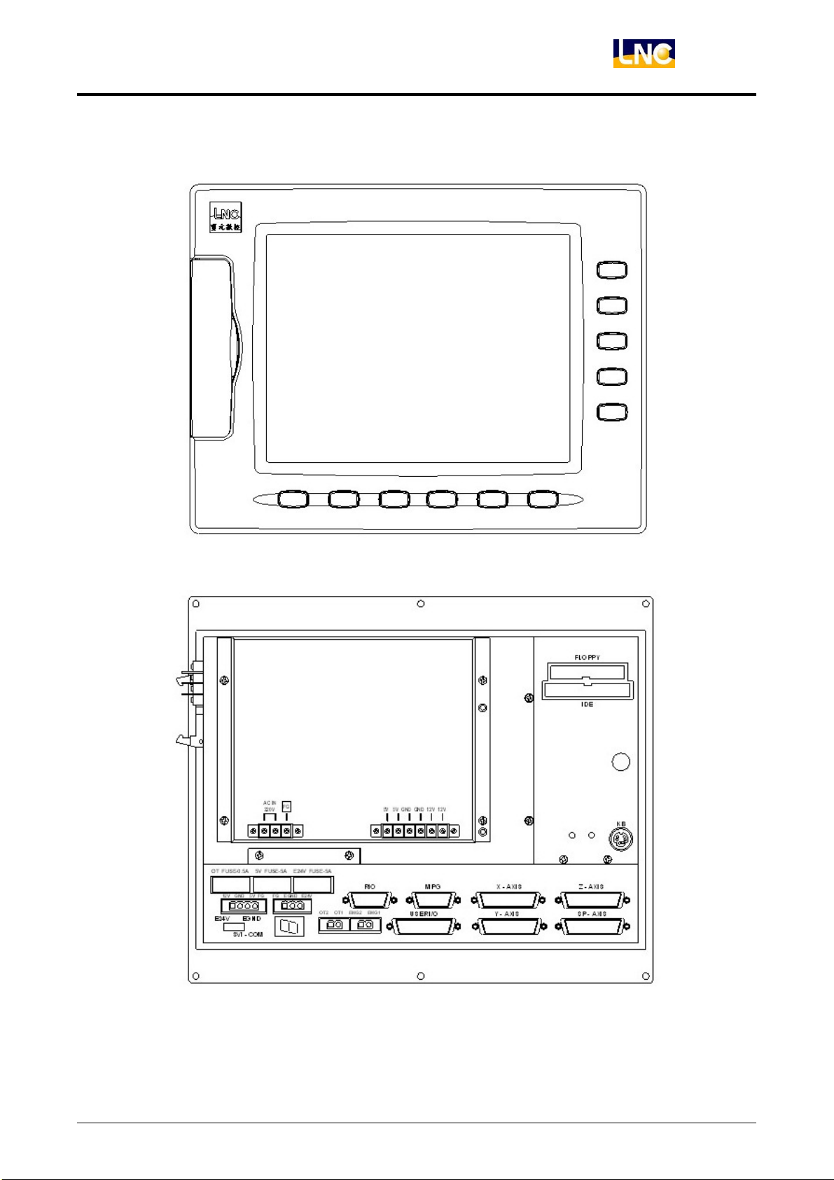
Port and interface
LNC-M600i
Hardware Maintenance
Controller Front View
Controller Back View
LNC Technology Co., Ltd. 13
Page 20
LNC-M600i
Hardware Maintenance
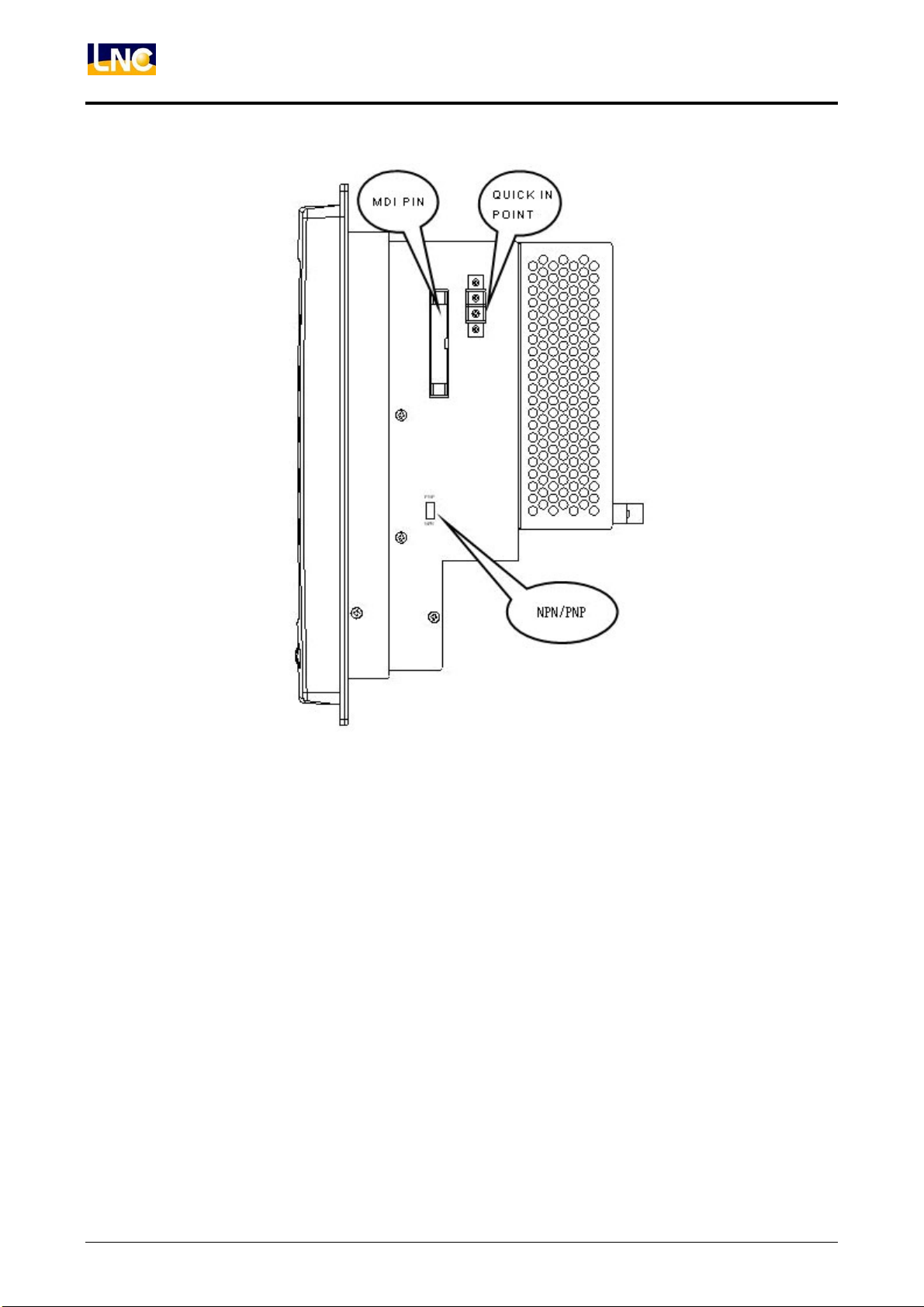
Controller Right View
14
LNC Technology Co., Ltd.
Page 21
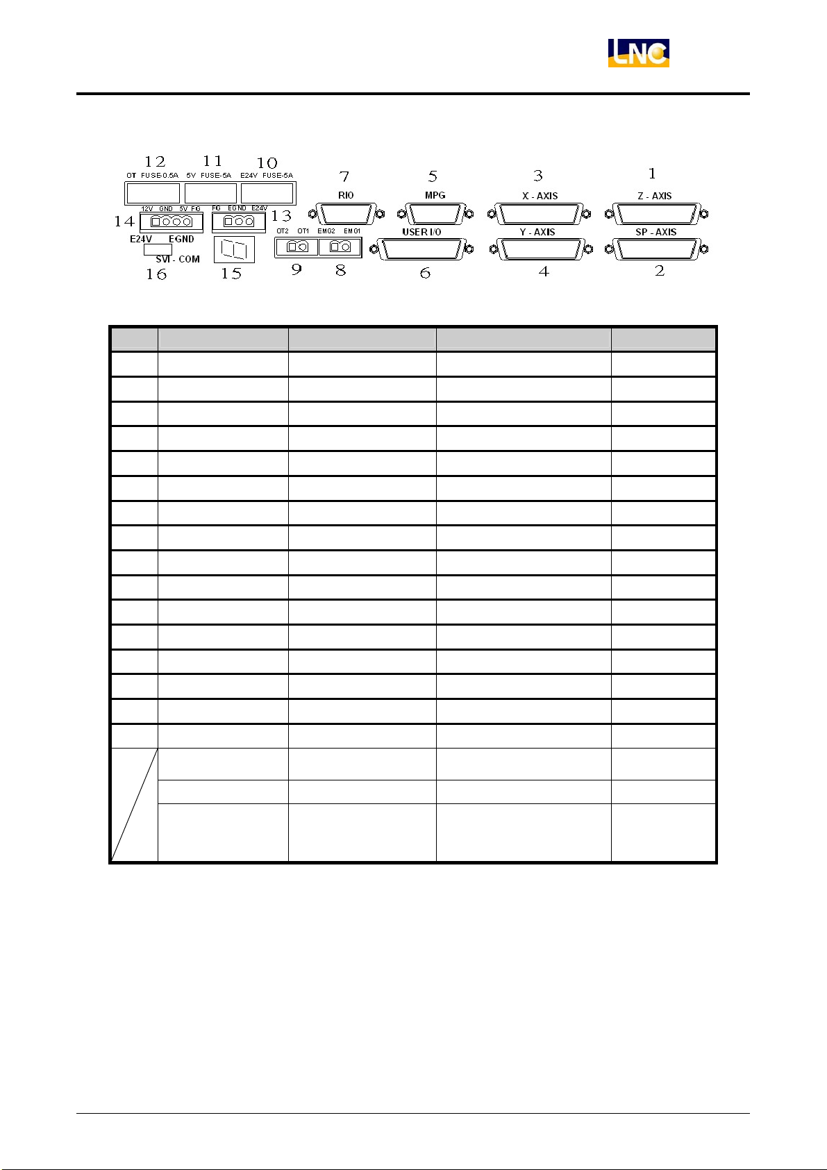
Hardware Maintenance
Mark Icon Code Function Connection Format Note
LNC-M600i
1 Z AXIS Z Axis servo control
2 Y AXIS Y Axis servo control
3 X AXIS X Axis servo control
4 SP AXIS Spindle
5 MPG MPG pin
6 USER I/O 20IN/16OUT interface
7 RIO IO control port
D-SUB 25 PIN(Jack)
D-SUB 25 PIN(Jack)
D-SUB 25 PIN(Jack)
D-SUB 25 PIN(Jack)
D-SUB 15 PIN(Jack)
HD_D-SUB 44 PIN(Plug)
D-SUB 15 PIN(Plug)
Commnad/IN
Connect REL
Connect SIO
8 EMG Connect Hardware protection
9 OT Connect Hardware protection
10 E24V FUSE Fuse 5.2*20mm Fuse 5A/250V
11 5V FUSE Fuse 5.2*20mm Fuse 5A/250V
12 OT FUSE Fuse 5.2*20mm Fuse 0.5A/250V
FG、EGND、E24V
13
12V、GND、5V、FG 12V、5V
14
External Power 24V 3pin 5.08mm terminal
3pin 5.08mm terminal
15 7 set of monitor Numerical view
16 SVI-COM Servo COM point Switch Default=EGND
NPN/PNP
USER IN standard
setting
Switch
switch at right
side
KB Keyboard port Ps2 Connect
CF Industrial CF card CFCard Connect
LNC Technology Co., Ltd. 15
Page 22
LNC-M600i
Hardware Maintenance
B C
D
F E
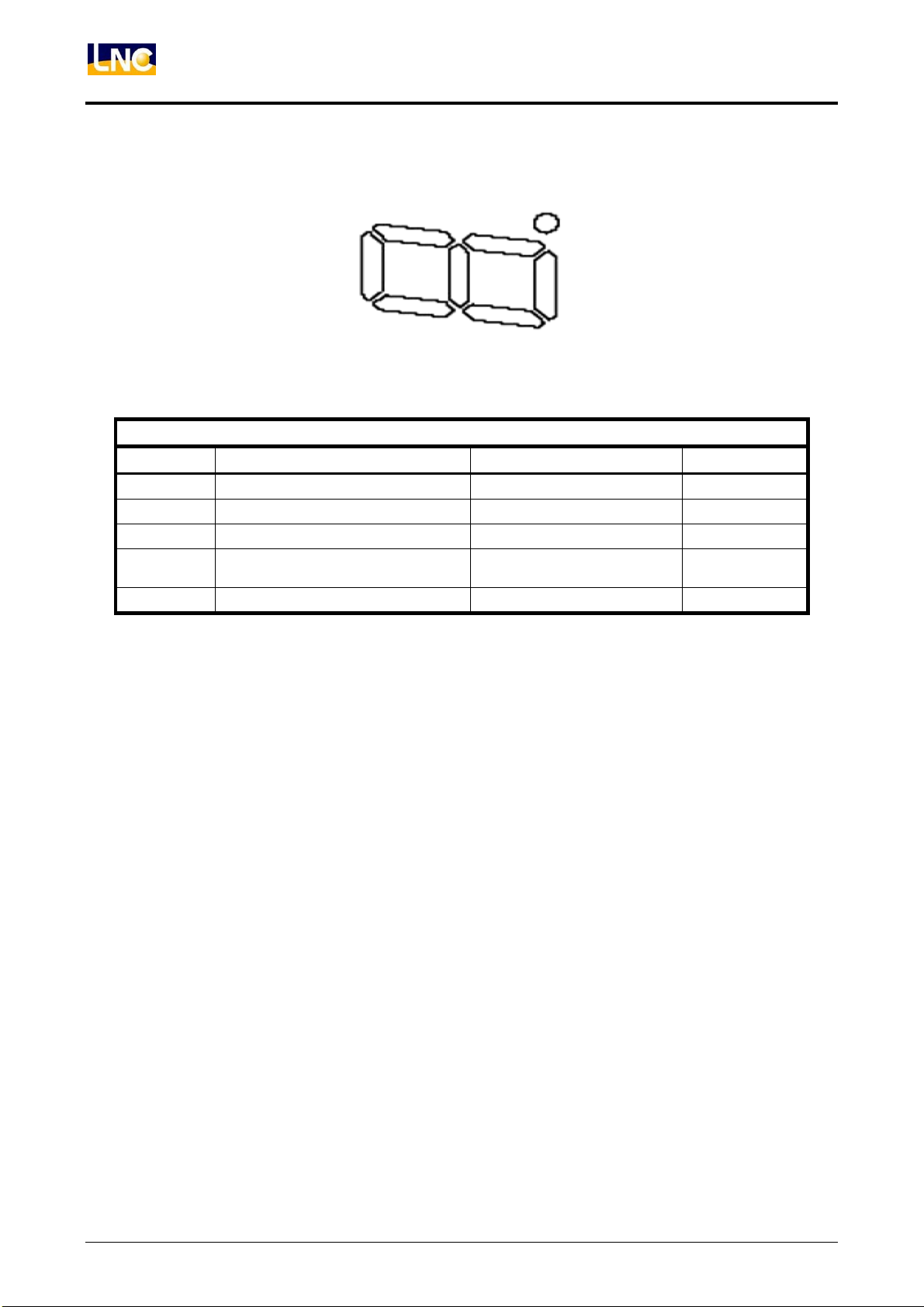
ELCLCD-2601 indicator lights as below:
LED lights ON Description OFF Description Exam and check
B External E24V input lights on No external E24V input Confirm E24V
C Servo reset lights on Servo is not at reset step
D Servo start lights on Servo is not at start step Confirm servo
E
Didn’t pass stroke lights on(OT1、
OT2short circuit)
OT1、OT2 open circuit
Confirm OT
F External E5V input lights on No external E5V input Confirm E24V
16
LNC Technology Co., Ltd.
Page 23
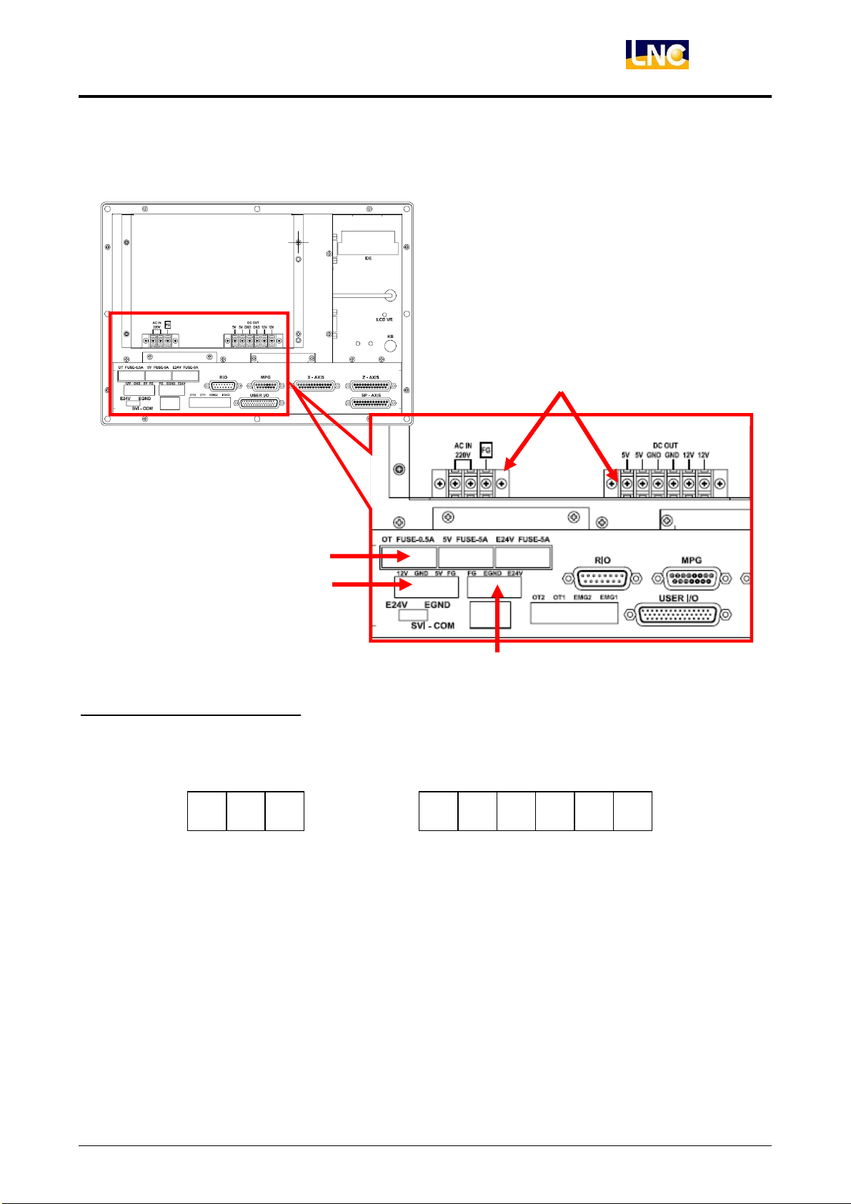
3.2 ELCLCD-2601 system connection and description
A、 POWER:
LNC-M600i
Hardware Maintenance
A-1
A-1:System Power Supply
◎Description:Offer 5V.12V power for system.
◎Connection:Connection as below:
AC IN FG
Put AC110V/220V power connect to power supply’s AC IN, FG to grounding, please connect with
metal chassis (grounding)
Power supply’s output 5V/12V/GND to connect with controller’s 12V/GND/5V pin.
A-4
A-2
A-3
5V
5V 12V
GND
GND
12V
LNC Technology Co., Ltd. 17
Page 24
LNC-M600i
Hardware Maintenance
z AC power cable:we recommend you use PVC cables and the cable diameter is
0.75 mm2 or above material (better within 5m).
z System powersupply is mainly used for offering controller system power,
except the accessories( like CF card), please do not use for other equipment.
A-2:System use 5V、12V pin
◎Description:Offer 5V,12V controller kernel power, use12V,5V and GND to connect to power supply
AC output;FG to grounding, please connect with metal chassis (grounding).
◎Power Demand:(1) 12V/2A;5V/6A or above
(2) Output voltage ripple and noise is smaller then 150mVp-p.
z Please kindly use LNC power supply(12V/3A、5V/11.5A) for system to use
5V,12V power. This device suits to LNC controller. LNC have passed the CE
test. We can not guarantee your needs without using this model.
A-3:E24V External Power Pin
◎Description:E24V offer controller power control and for external IO to use.
◎Connection:Connection as below:
E24V and EGND connect to external power supply AC output side;FG to grounding, please connect
with metal chassis (grounding).
◎Power Demand:(1) E24V/5A above.
(2) Output voltage ripple and noise is smaller then 150mVp-p.
z We recommend you to use MW ADS-15524
With using this model, LNC have passed the CE test. We can not guarantee
your needs without using this model.
z When using this power supply, please make sure the installation location will
not be too far( DC output may have drop voltage, especially All in one series )
After booting, E24V power supply voltage will need to stay within E24V±0.5V.
FG
EGND
E24V
power supply(E24V/5.8A、E5V/3A).
18
LNC Technology Co., Ltd.
Page 25
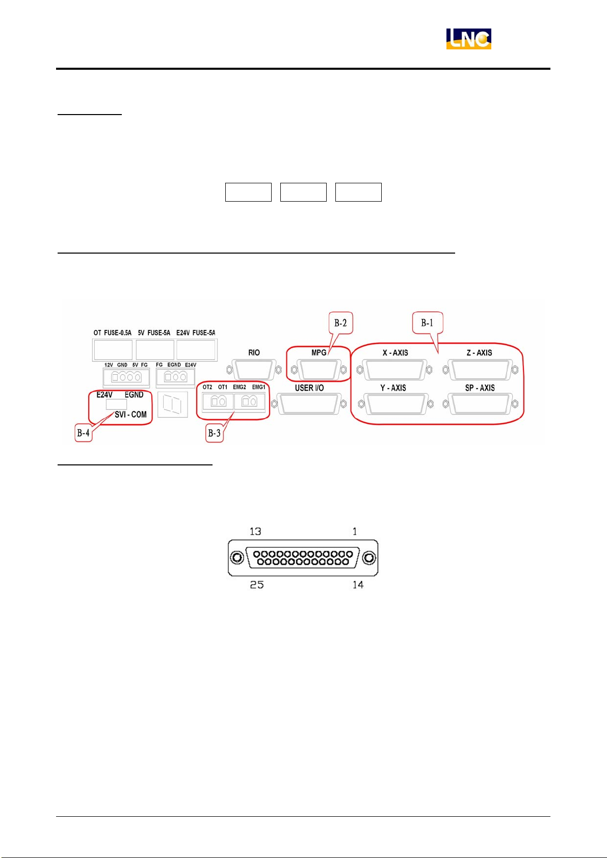
A-4:FUSE
◎Description:Fuse is the circuit protection. When controller has strange situation, please check if
◎Position:Relating position is as below:
LNC-M600i
Hardware Maintenance
fuse is OK.
OT
5V E24V
◎Fuse Specification: 5V、E24V、5V is all 250V/5A;OT is 250V/0.5A.
B、Motion Control:
B-1:Servo Control Connect
◎Description:B-1 offer 3 axis control pin(X、Y、Z) to connect and control back side drives.
◎Connection:UseD_SUB 25PIN(Jack) connect, details as below:
LNC Technology Co., Ltd. 19
Page 26
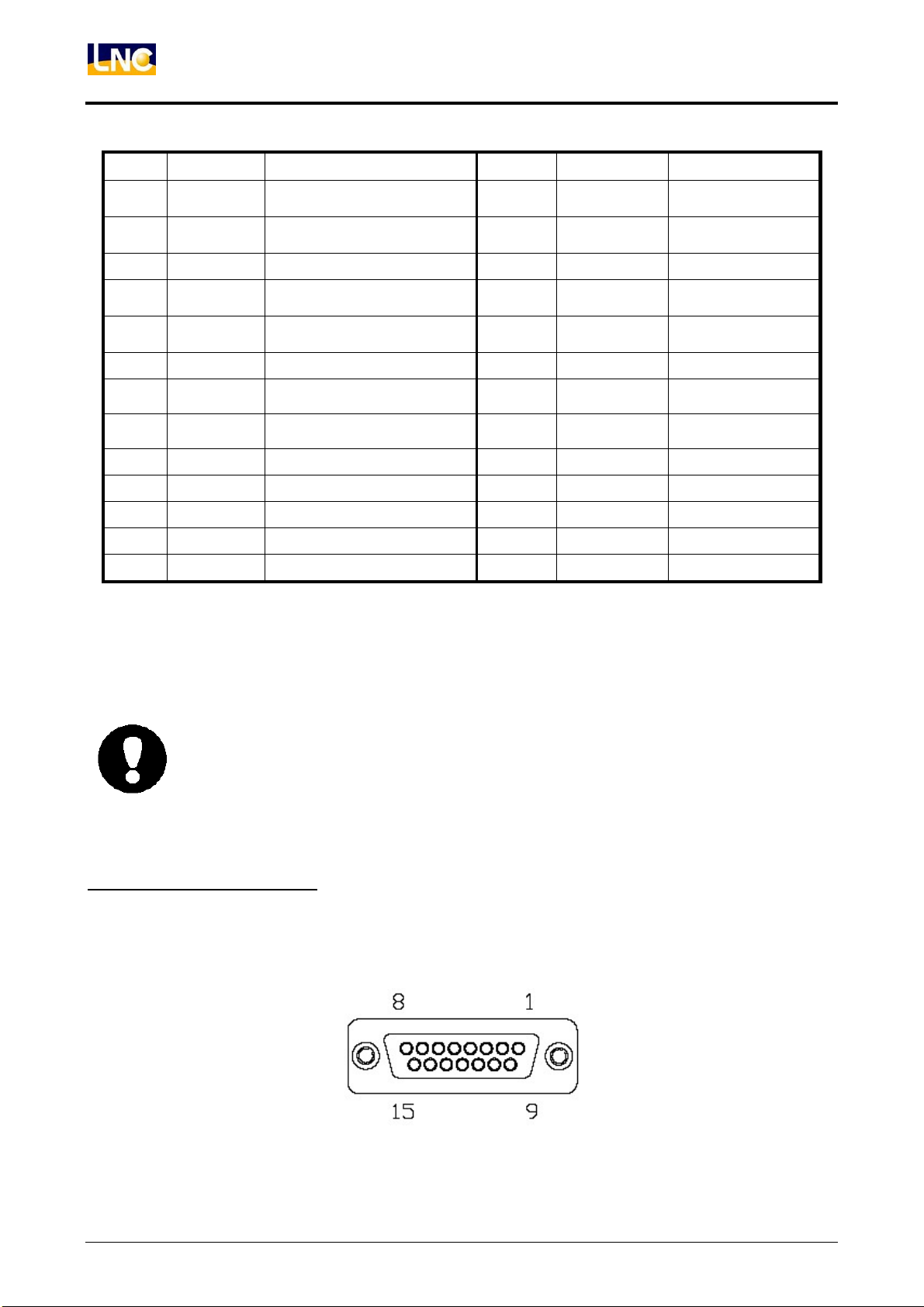
LNC-M600i
Hardware Maintenance
PIN Name Description PIN Name Description
1 /PB Pulse Output B Opp. P 14 /PA
2 PB Pulse Output B Phase 15 PA
3 E5V
External E5V of Linear Scale
16 - -
4 EGND External Power 17 DACO
5 AGND Anlog Output 18 E24V
6 SRV_ON Servo Start Control 19 ALARM Servo Alarm
7 EGND
External power(E5V、E24V)
20 SVI_COM
8 SVI_COM Servo COM Setting 21 EGND
9 SRV_RST Servo Reset Signal 22 - -
10 C Encoder C Phase 23 /C Encoder C Phase
11 A Encoder A Phase 24 /A Encoder A Phase
Pulse Output A
Opp. P
Pulse Output A
Phase
Analog Voltage
Output
External Power
E24V
External Power
(E5V、E24V)
External Power
(E5V、E24V)
12 B Encoder B Phase 25 /B Encoder B Phase
13 FG Chassis - - -
◎Description:(1) Pulse output and encoder feedback are all differential signals.
(2) Analog voltage output is ±10V.
(3) SP axis analog voltage DACO3 is standard device;X/Y/Z axis analog voltage
(DACO0~DACO2) output is optional.
z When making the connection cables of control pin and back-end driver, please use
better shielding cover and cables (A.W.G24 UP) And make sure the connection of
shielding cables to reduce the chance of noise interference. LNC offers standard
cables for selection
z Please don’t bind signal control cables with power cables at the same time or put
at the same cable box.
B-2:MPG Control Connect
◎Description:This control pin is to connect MPG handwheel which contains pulse and I/O signals
inside.
◎Connectio:UseD_SUB 25PIN(Jack) connect, details as below:
20
LNC Technology Co., Ltd.
Page 27
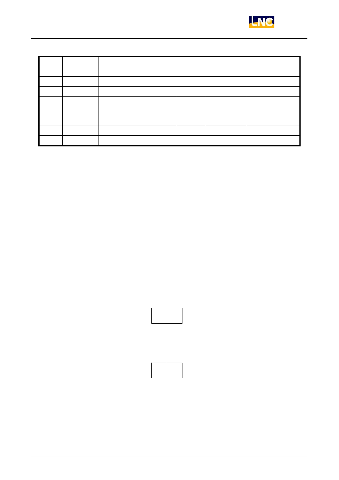
LNC-M600i
Hardware Maintenance
PIN Name Description PIN Name Description
1 E24V MPG E24V 9 EGND MPG power
2 MPG4 MPG select 4 10 FG grounding
3 E/B Encoder B phase 11 EB Encoder B phase
4 E/A Encoder A phase 12 EA Encoder A phase
5 X100 MPG ratio100 13 X10 MPG ratio 10
6 MPGZ MPG select Z 14 MPGY MPG selectY
7 MPGX MPG select X 15 E5V MPG E5V
8 E5V MPG E5V - - -
◎Description:(1) Encoder responses are all differential signals.
(2) This pin offer 6 sets of 24V input for axis direction and ratio selection to use.
B-3:OT and EMG Connect
◎Description:(1) OT connect is a overtravel point and a safepoint to protect hardware.Normally will
be at short-circuit situation.
(2) When you want to make servo on, you will need to make OT and EMG to be short
circuit, therefore OT object is close pin. When using several OT objects, please
connect with serial way, and EMG will be short circuit state at normal using.
(3) With MDIOP series, you need to connect EMG on MDIOP to another EMG pin,
this function will be valid.
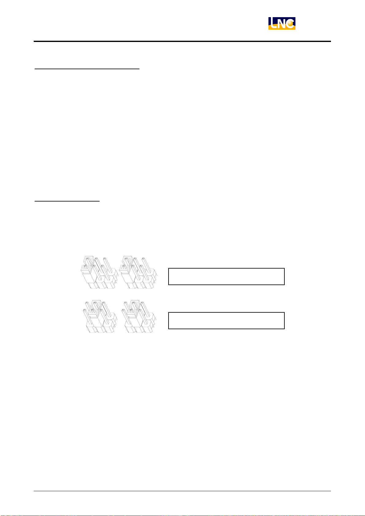
◎OT connection:Picture and pin definition as below.
◎EMG connection:Picture and pin definition as below.
OT2 OT1
EMG2 EMG1
LNC Technology Co., Ltd. 21
Page 28
LNC-M600i
Hardware Maintenance
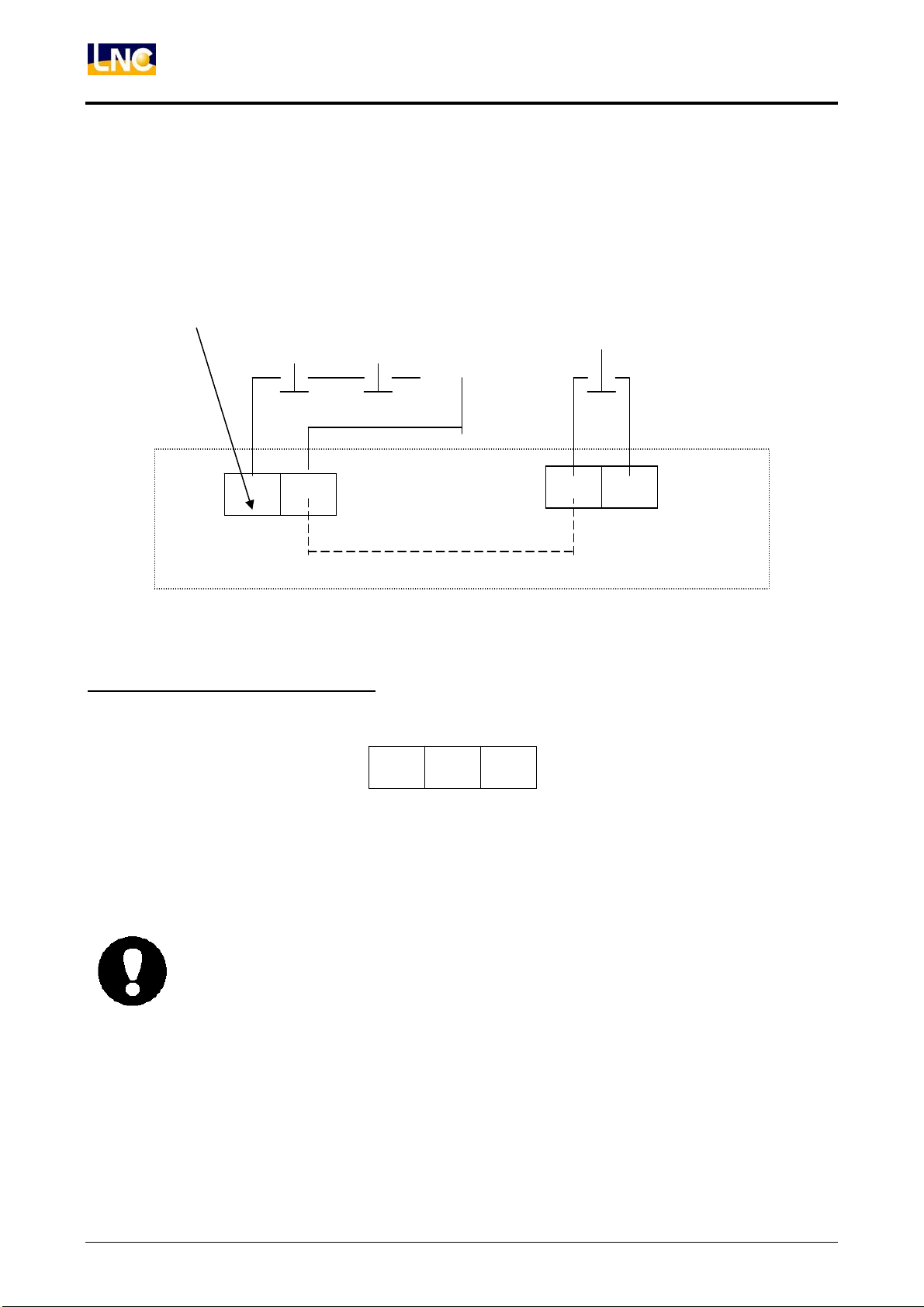
OT only offer 2 pin for connection, if you have more overtravel pics, you will need to collocate with
EMG, connection is as below:
Connect to controller IN
point, can detect OT
connect signal (24V)
Series circuit b pin
OT1 OT2
B-4:Servo Input SVI-COM Switch
◎COM switch description:Picture and pin definition as below.
B pin
…
EMG2 EMG1
Controller inside
22
E24V
SW turns to right side EGND, servo’s IN COM port will be set to be EGND(default).SW turns to left
side E24V, servo’s IN COM port will be set to be 24V.
z SVI-COM and B-1:Connect with each servo system 20th PIN.
z SVI-COM points will depend on servo drives, please refer to drives manual.
Switching error will make the drive does not work.
z When changing SW, please turn off power and do not process when power on to
protect hardware.
SVI-COM
EGND
LNC Technology Co., Ltd.
Page 29
C、IO Control:
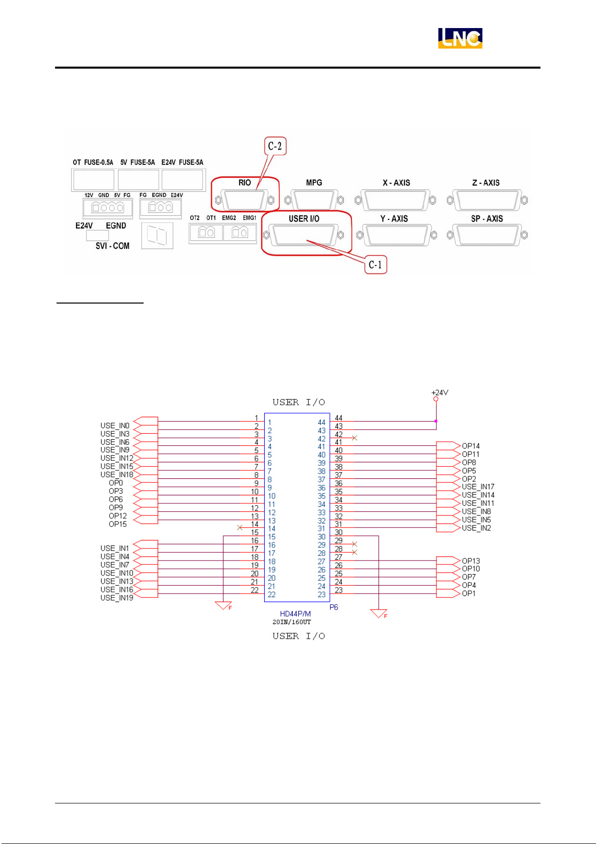
C-1:USER IO
◎Description:C-1offers 20IN/16 OUT-IO interface, usually for connection with REL.
◎Pin description:Adopts HD_SUB 44PIN(Plug), details as below:
LNC-M600i
Hardware Maintenance
USER I/O PIN
LNC Technology Co., Ltd. 23
Page 30
LNC-M600i
Hardware Maintenance
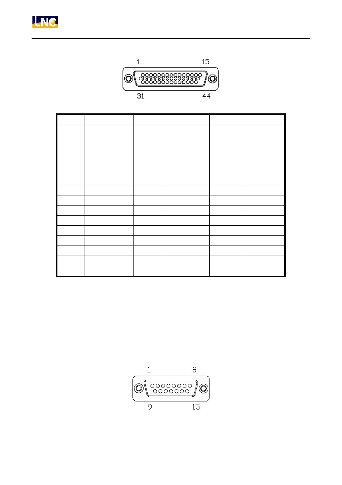
PIN Description PIN Description PIN Description
1 IN00 16 IN01 31 IN02
2 IN03 17 IN04 32 IN05
3 IN06 18 IN07 33 IN08
4 IN09 19 IN10 34 IN11
5 IN12 20 IN13 35 IN14
6 IN15 21 IN16 36 IN17
7 IN18 22 IN19 37 OUT02
C-2:RIO
◎Description:(1) C-2 offers IO expansion interface, when USER IO is not enough, you can connect
◎Pin description:Adopts D_SUB 15PIN(Plug) to connect with SIO, one on one.
8 OUT00 23 OUT01 38 OUT05
9 OUT03 24 OUT04 39 OUT08
10 OUT06 25 OUT07 40 OUT11
11 OUT09 26 OUT10 41 OUT14
12 OUT12 27 OUT13 42 -
13 OUT15 28 - 43 E24V
14 - 29 - 44 E24V
15 EGND 30 EGND - -
with SIO/EIO from here to do expansion of IO points.
(2) With MDIOP series, please connect to MDIOP module serial communication
header.
24
LNC Technology Co., Ltd.
Page 31
D、Side pin :
LNC-M600i
Hardware Maintenance
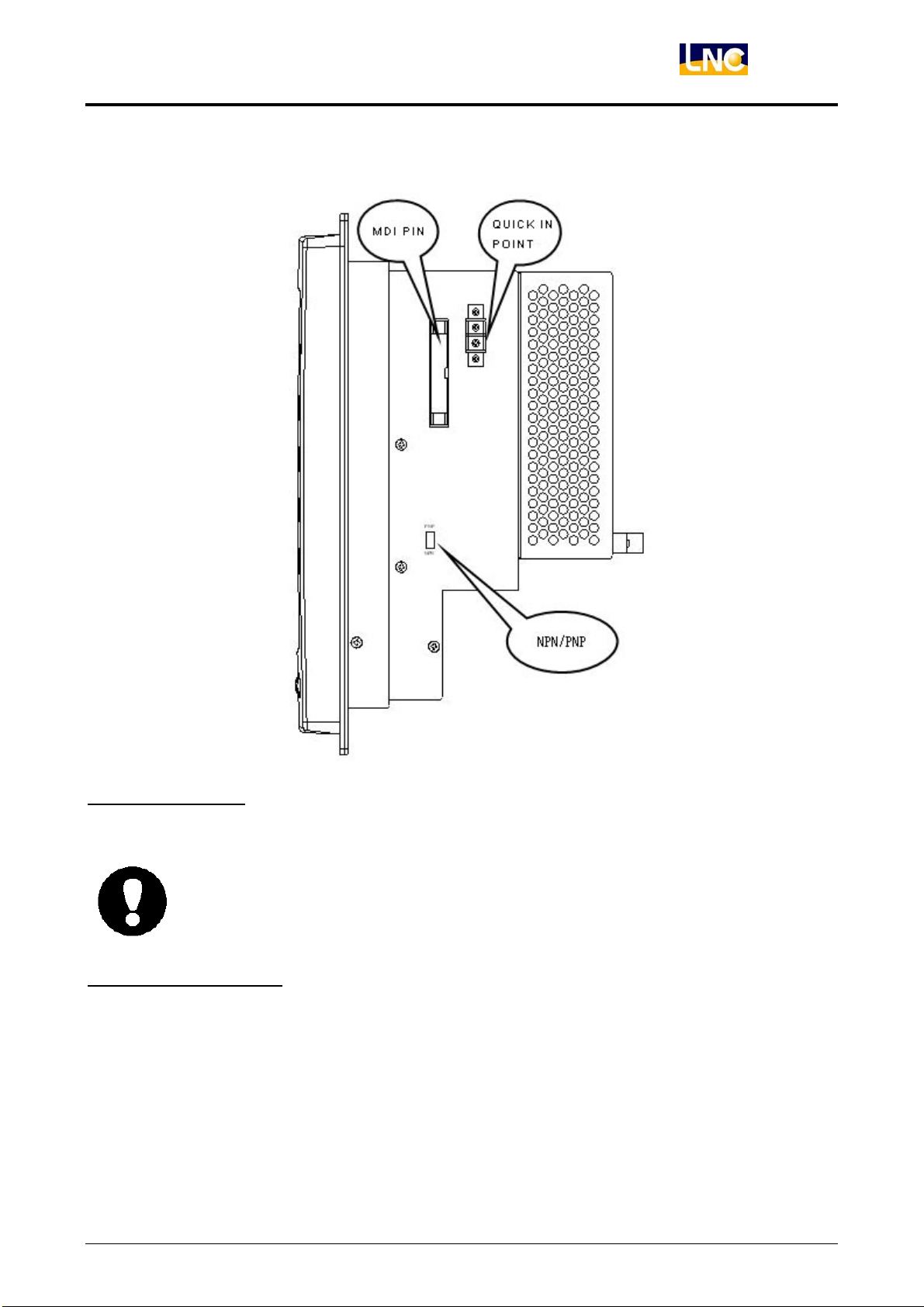
D-1:MDI Connect
◎Description:MDI offers button decoder interface to connect with MDIOP module.
◎Pin description:Adopts 2.54mm 26PIN(Plug)
z IDE connection cable installation- please be sure to buckle into the connector,
MDI's key can work properly.
D-2:Quick IN Connect
◎Description:IN points is 24V standard input.
◎Pin description:Upper terminal blocks are IN, below is EGND
LNC Technology Co., Ltd. 25
Page 32

LNC-M600i
Hardware Maintenance
D-3:NPN/PNP Switch
◎Description:This switch is USER IO-20 IN points, can be set according to different situations.
◎Usage:
PNP:IN point is 24V action (default)
NPN:IN point is EGND action.
Note:This 20 In point will need to be changed at one time, can not be changed separately.
26
LNC Technology Co., Ltd.
Page 33
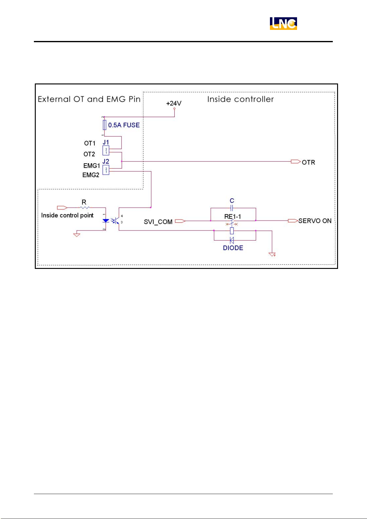
3.3 OT/EMG PIN
LNC-M600i
Hardware Maintenance
Same as this picture, if you want to make servo on, you need to make OT and EMG to be short circuit.
Therefore OT head is usual close point. When using multi OT components, please use serial connection to
connect. And as for servo on’s signal standard can be changed by SW of SVI_COM. Meanwhile LNC-M600i
offer 1 RELAY to do SERVO_ON control. SERVO_ON’s control signal is sent by software, but will also be
protected by hardware. EMG_SIG need to have 24V, then SERVO_ON.
Circuit only offers OT1、OT2、EMG1、EMG2, 4 motion relating points. Please make it short circuit when in no
use.
OT、EMG connection way:
LNC Technology Co., Ltd. 27
Page 34

LNC-M600i
Hardware Maintenance
OT1 B Pin
EMG B Pin
OT2 B Pin
……
OT1
OT2
EMG1
EMG22V
28
LNC Technology Co., Ltd.
Page 35
LNC-M600i
Hardware Maintenance
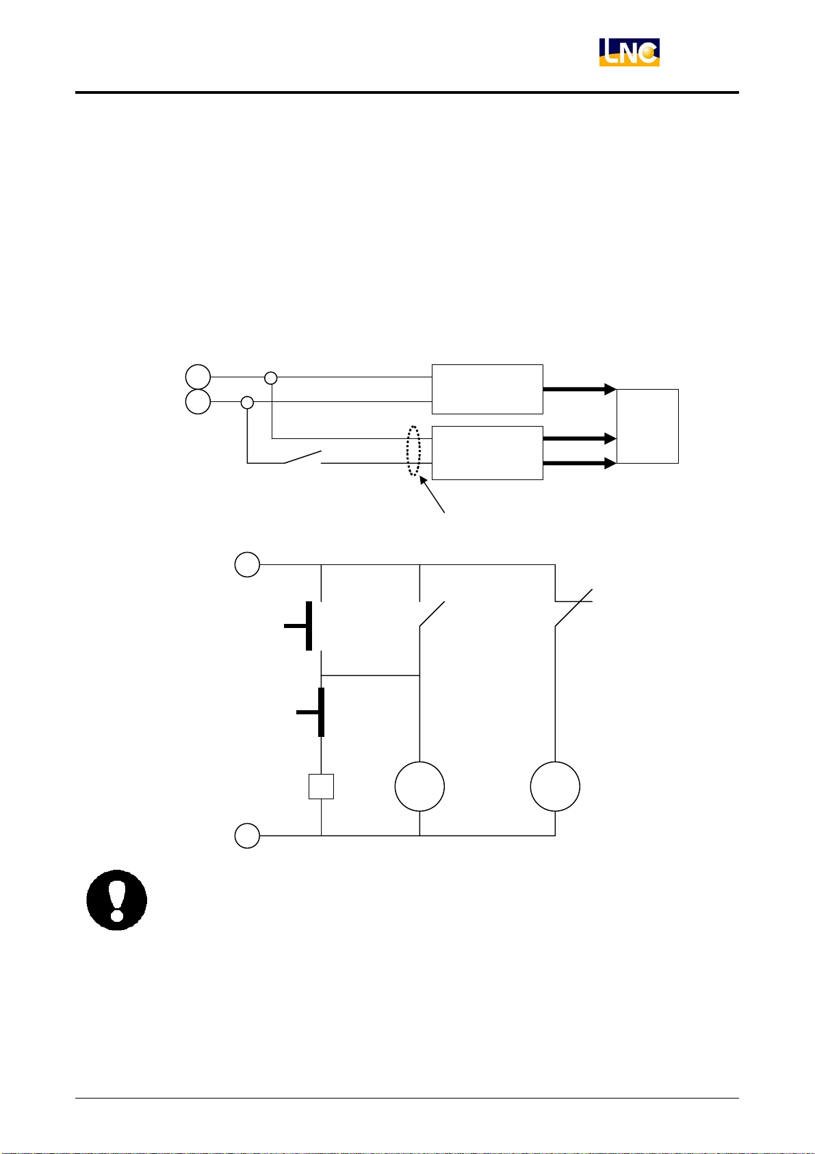
External ON/OFF System Power Control with 2 switched
Description:After giving AC power to the back side power point of LNC-600i, System wil be ON. If you need
to control by external power, connection will be as below:
Demand Material:
1. RELAY:DC24VCoil 2AB connect’s rated power is 5A UP (1PCS)
2. Switch:DC24V Reversion type witch with lights(Red/green)-each 1PCS.
AC1
AC0
RELAY 1C pin RELAY 1A pin
E24V
ON A pin
OFF B pin
RELAY 2Cpin
RELAY 2A pin
ON Light(green) OFF light(red)
24Power
E24V
5V
Back power
12V
Bk Power AC IN pin
2601
system
RELAY 2B pin
RELAY Coil
EGND
z When using RELAY, please take more care on the protection of pin to increase pin
using life.
LNC Technology Co., Ltd. 29
Page 36
LNC-M600i
Hardware Maintenance
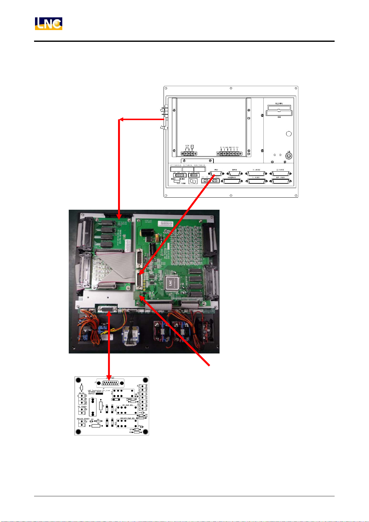
ELCLCD-2601with MDIOP module/TRF9500 connection:
PART1:ELCLCD-2601/ MDIOP-8500 / TRF9500
MDI
ON/OFF
RIO
MDIOP-8500 Module
E24VTRF9500
30
LNC Technology Co., Ltd.
Page 37
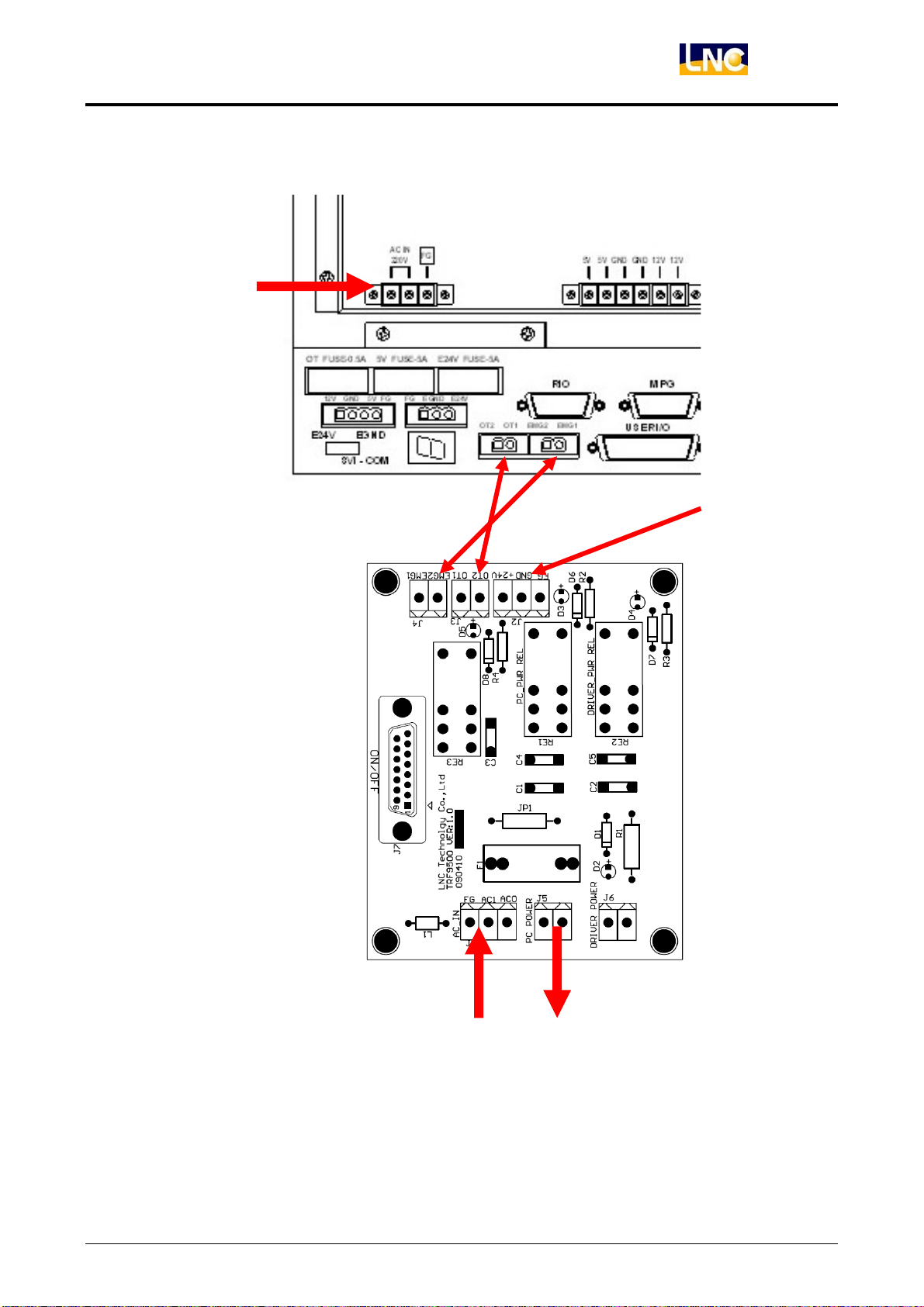
PART2:TRF9500 / ELCLCD-2601 System Connection
POWER
LNC-M600i
Hardware Maintenance
E24V
TRF9500
AC IN
Note:Conenct OT Pin from TRF9500 with ELCLCD-2601-OT pin by parallel, MDIOP’s OTR button can be
valid.
LNC Technology Co., Ltd. 31
POWER
Page 38
LNC-M600i
Hardware Maintenance
3.4 Hardware Module Description
3.4.1 I/O Module
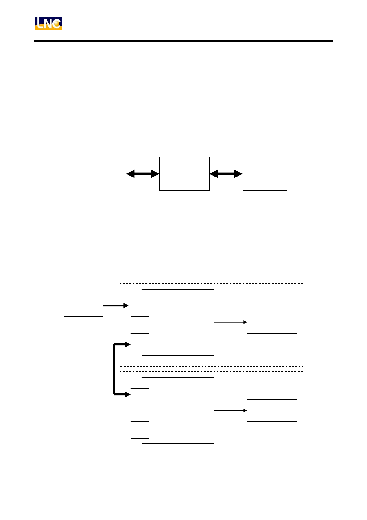
Controller system adopts serial transmission method of IO expansion, max control port can up to 2 sets of
I/O( according to control side hardware ). Each I/O port’s max control points will also be different depends on
controllered side hardware.
z Serial I/O module as below:
Serial Control
Controller/Motion card
z Serial I/O expansion connection as below:(Each port can have serial connection, max to 2
controlled components.)
Serial
Control
P 1
P 2
Seiral controlled
SIO-1520
SIO-1540
EIO-2000
OP
Slave1
Serial Controlled Side
User Interface
REL-2840
REL
32
Slave2
P 1
Serial Controlled Side
P 2
REL
LNC Technology Co., Ltd.
Page 39
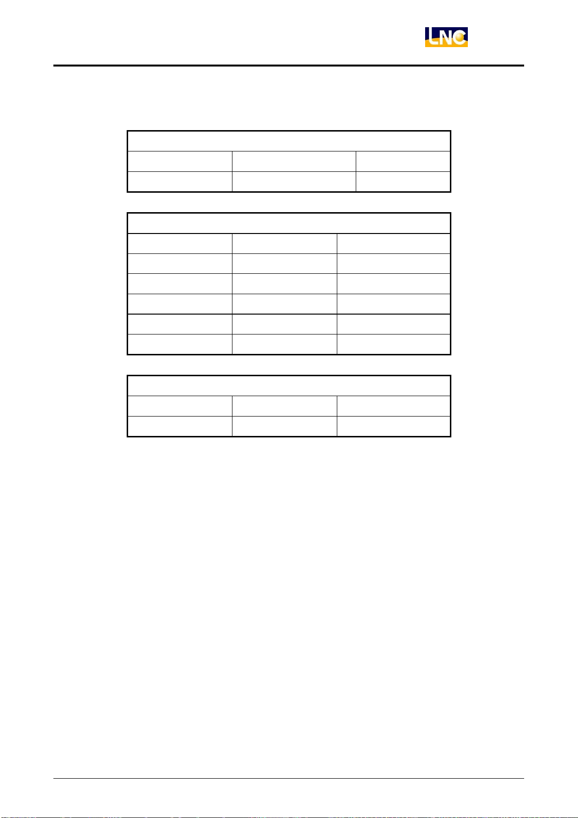
SERIES I/O EXPANSION PIN DESCRIPTION:
1、EACH OBJECT SPECIFICATION:
MASTER
HARDWARE NO. EXPANSION I/O PORT NOTE
ELCLCD-2601 1
SLAVE,EACH HARDWARE CAN CONNECTED WITH SERIES
HARDWARE NO. I/O CONTROL PIN NOTE
SIO-1540 40IN / 32OUT
EIO-2000-1 40IN / 32OUT
EIO-2000-2 60IN / 48OUT
LNC-M600i
Hardware Maintenance
SIO-1520 40IN / 32OUT USED FOR OP
OP-2520 64IN / 64OUT USED FOR OP
USER INTERFACE
HARDWARE NO. I/O POINTS NOTE
REL-2840 20IN / 16OUT
2、I/O POINTS CALCULATION:
(1) If use ELCLCD-2601 to work with EIO-2000-2, max I/O is
1(CONTROL PORT) × 2( EIO-2000-2) × 60 IN = 120IN
1(CONTROL PORT) × 2( EIO-2000-2) × 48 OUT = 96 OUT
(2) If use ELCLCD-2601 to work with I/O SIO-1540, max I/O is
1(CONTROL PORT) × 2( SIO-1540) × 40 IN = 80IN
1(CONTROL PORT) × 2( SIO-1540) × 32 OUT = 64 OUT
And so on.
z Each hardware usage, please refer to each module manual.
LNC Technology Co., Ltd. 33
Page 40
LNC-M600i
Hardware Maintenance
3.4.2 I/O card SIO 1520 definition
3.4.2.1 I/O card SPEC
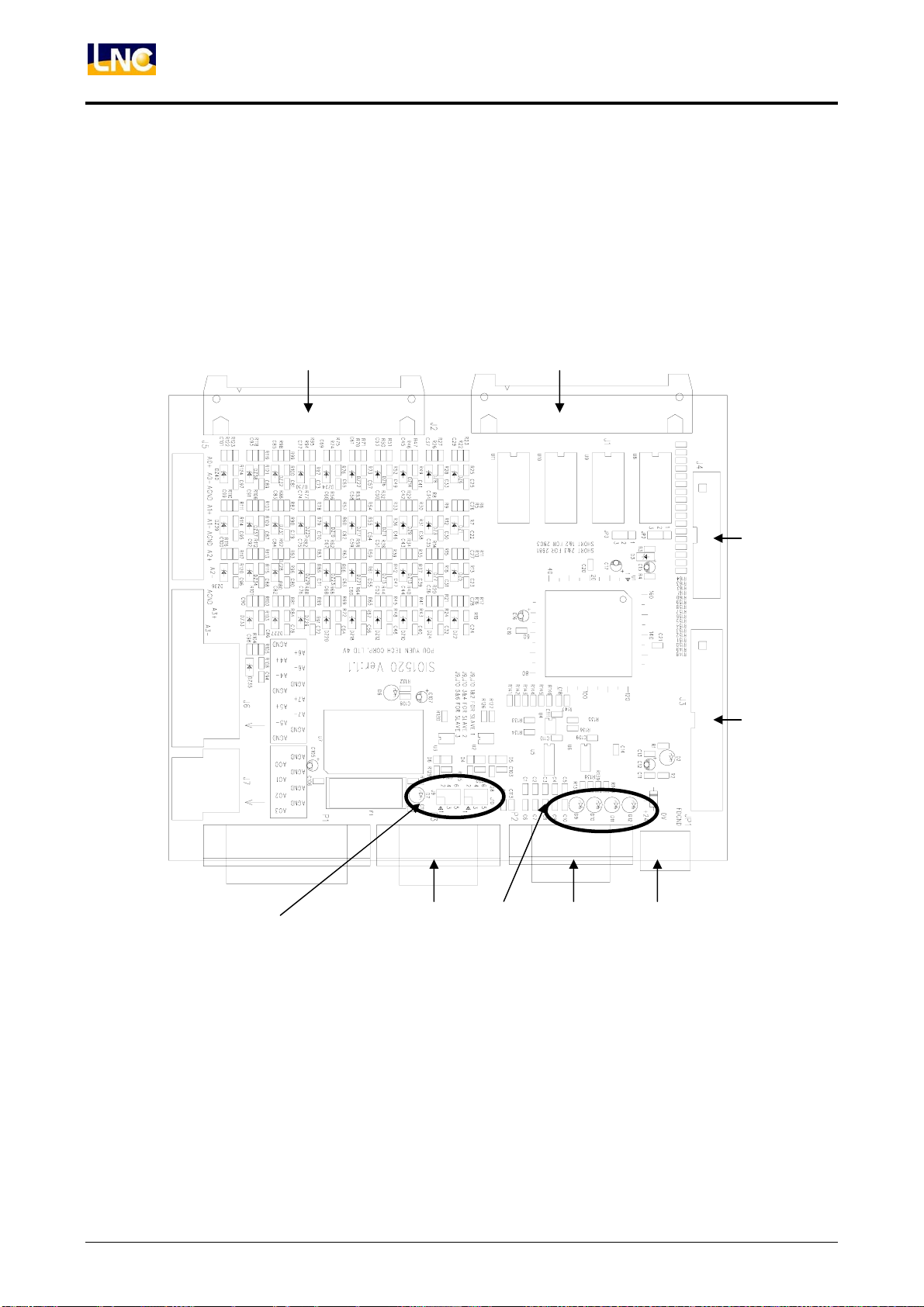
1、Description:
1 SIO-1520only offers 40IN /32 OUT( other 24IN / 32 OUT optional)。
2、Hardware Layout:
D E
H I
A B C
G
F
34
LNC Technology Co., Ltd.
Page 41
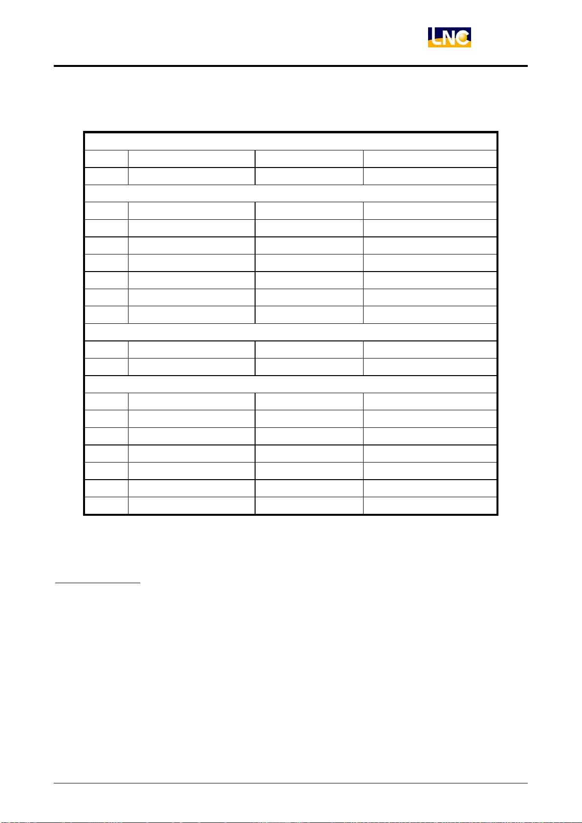
3、Connect and components:
Power
Pic Component Function Description
A 3PIN 5.08mm head DC(24V)power input Connect to POWER
IOConnection
Picture Component Function Description
B D_SUB LD 15PIN Plug Serial port Connect to controller RIO
C D_SUB LD 15PIN Jack Serial port Connect to controller RIO
D 40PIN 2.54 mm head 32 OUT 24V Output
E 40PIN 2.54 mm head 40IN 24V Standard
F 40PIN 2.54 mmeasy head Spare 32 O points Option
G 26PIN 2.54 mmeasy head Spare 24 I points Option
LNC-M600i
Hardware Maintenance
Setting
Picture Component Function Description
H 2.54mm JUMPER SLAVE pointed Detail
Indicator
Picture Component Function Description
I E5V green LED(D8) E5V indicator light E5V normal>ON
E24V green LED(D2) E24V indicator light E24V normal>ON
CS yellow LED(D11) Sending state light Connect to controller>On
DO yellow LED(D12) Sending state light Connect to controller>On
DI yellow LED(D9) Sending state light OK>Lights on
LK yellow LED(D10) Sending state light OK>Lights on
4、Setting:
A:E24V Power
◎Description:This pin is for O point outpur power, if this pin has problem, O point output will be error.
(Has no effect to IN point)
◎Rated Capacity:E24V±0.5V (3A UP)
LNC Technology Co., Ltd. 35
Page 42
LNC-M600i
Hardware Maintenance
C:Serial Connection
◎Description:1.B,C head is for serial connection, need to connect with controller’s RIO port.
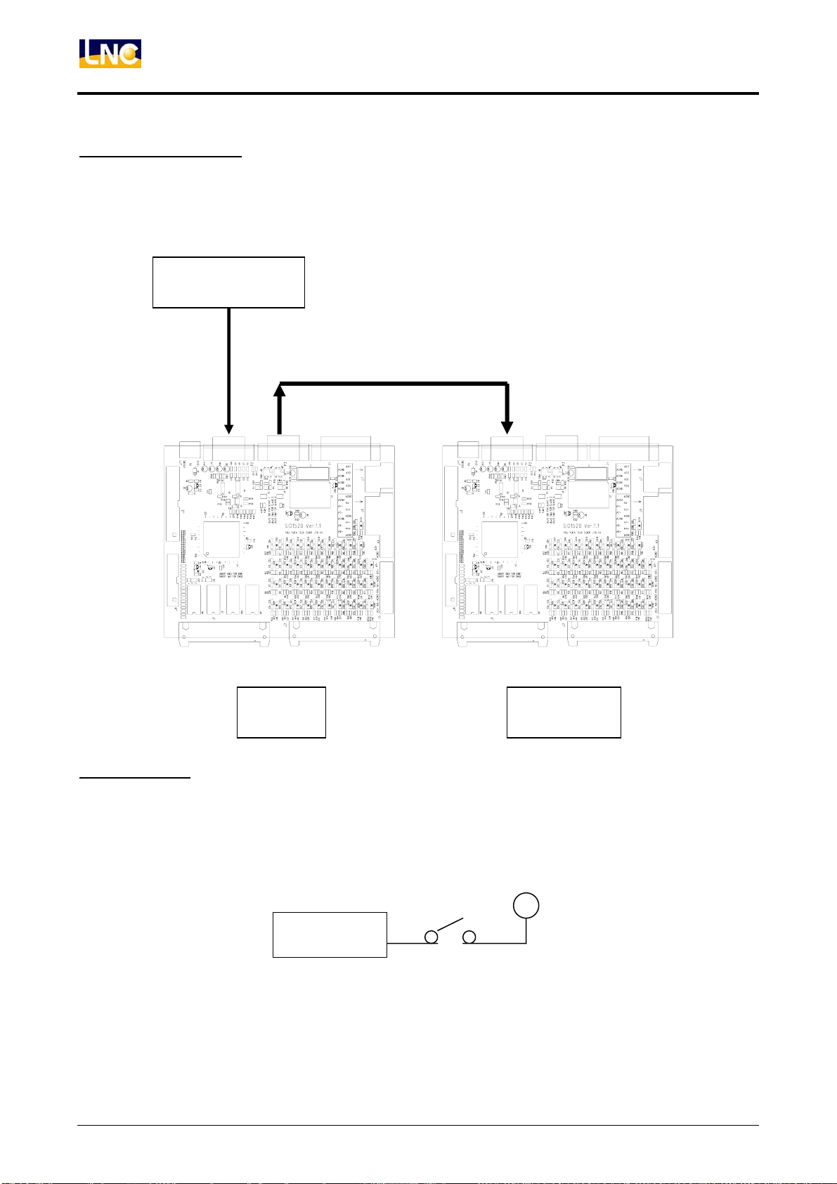
2.B,C head is pararell signal, is for serial expansion to use.
◎Serial expansion example:Serial connection for 2 SIO-1520 cards.
Controller RIO
(LD15PIN 1 to 1 Plug/Jack transmission line)
D、E:IO Port
◎Description:D head contains 32 sets of 24V OUT, and E head contains 40 sets of IN.
◎IN points as below:
SLAVE1 SLAVE2
E24V
SIO- IN
36
LNC Technology Co., Ltd.
Page 43
LNC-M600i
Hardware Maintenance
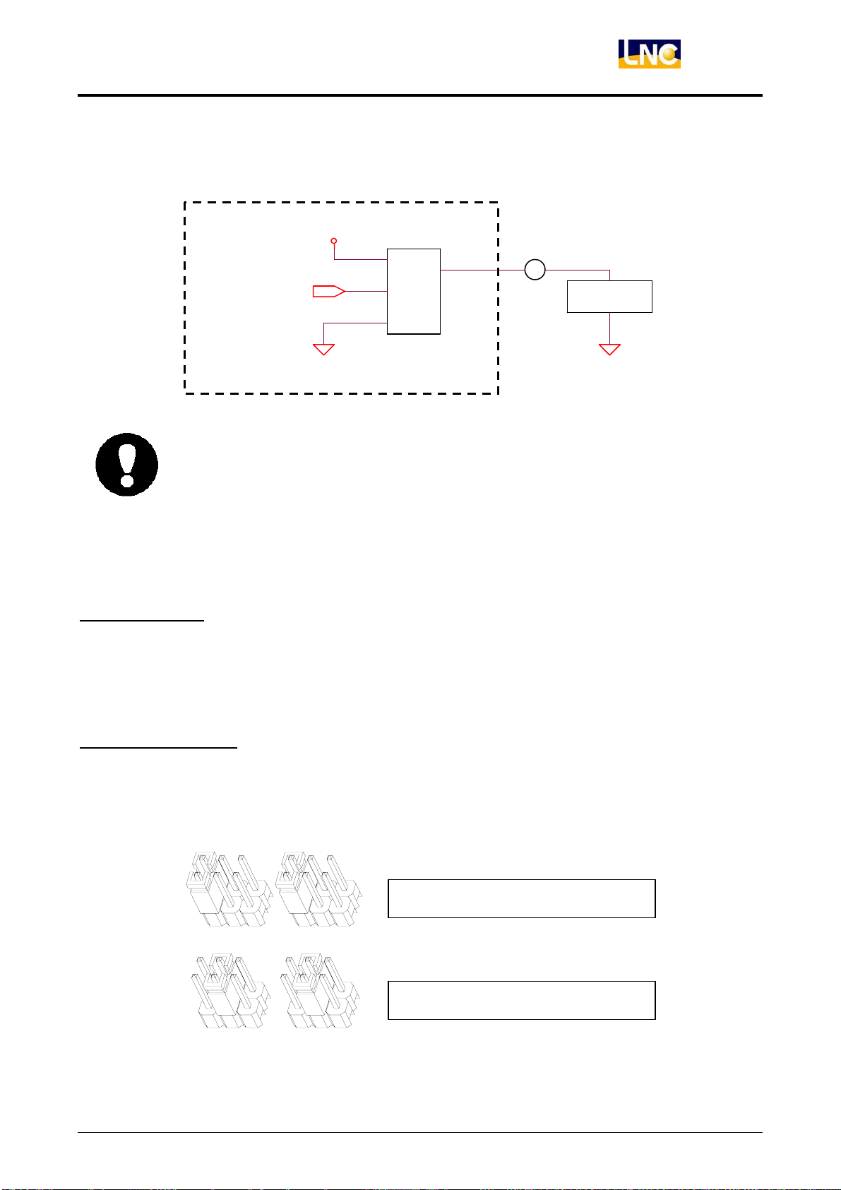
◎O point direct usage:
O type is SOURCE TYPE, motion output is E24V, max voltage is 60mA.
IO module
z Please do not make the current more then 60 mA, when doing load selection.
z When O point grounds, if shortcircuit happens, IC will burn out instantly, please
F、G:Spare IO
◎Description:1 F、E head reserve 32OUT/24IN-IO『control interface』, this interface can not be
E24V
OUTPUT
OU T_D ATA
SOURCE TYPE IC
EGND
Otherwise it may have damage to components. E24V/60 mA=400Ω Å Load
resistance can not be less than this value.
pay special attention to is.
LOAD
EGND
H:SLAVE JUMPER
◎Description:SLAVE number setting, after setting, you need to coordinate with software, PLC plan to
work normally. Please do not change randomly.
◎Setting Example:
1 1
directly used, need to coordinate with SIO-1530 card.
To be SLAVE1, JUMPER Setting
To be SLAVE2, JUMPER Setting
1 1
LNC Technology Co., Ltd. 37
Page 44

LNC-M600i
Hardware Maintenance
I:Communication/Power Indicator Light
◎Description:
(1) E5V Indicator light:when SIO-1520 module connects with controller system, sending power,
indicator light will be ON, that means the module power is complete.
(2) CS、DO Indicator light:If SIO-1520 connect with controller correctly, sending power, CS and DO
will ON. If these two lights didn’t ON at the same time, there may be some errors in it, there will
also have problems after later transmission.
(3) K、DI Indicator light:When CS、DO Indicator light On, If SIO-1540 module’s SLAVE number
setting is the same to PLC setting, LK、DI will ON.
(4) 24V Indicator light:When E24V Indicator light ON, that means the O interface power OK, but if
it’s OFF, O point will not have feedback.
38
LNC Technology Co., Ltd.
Page 45
Hardware Maintenance
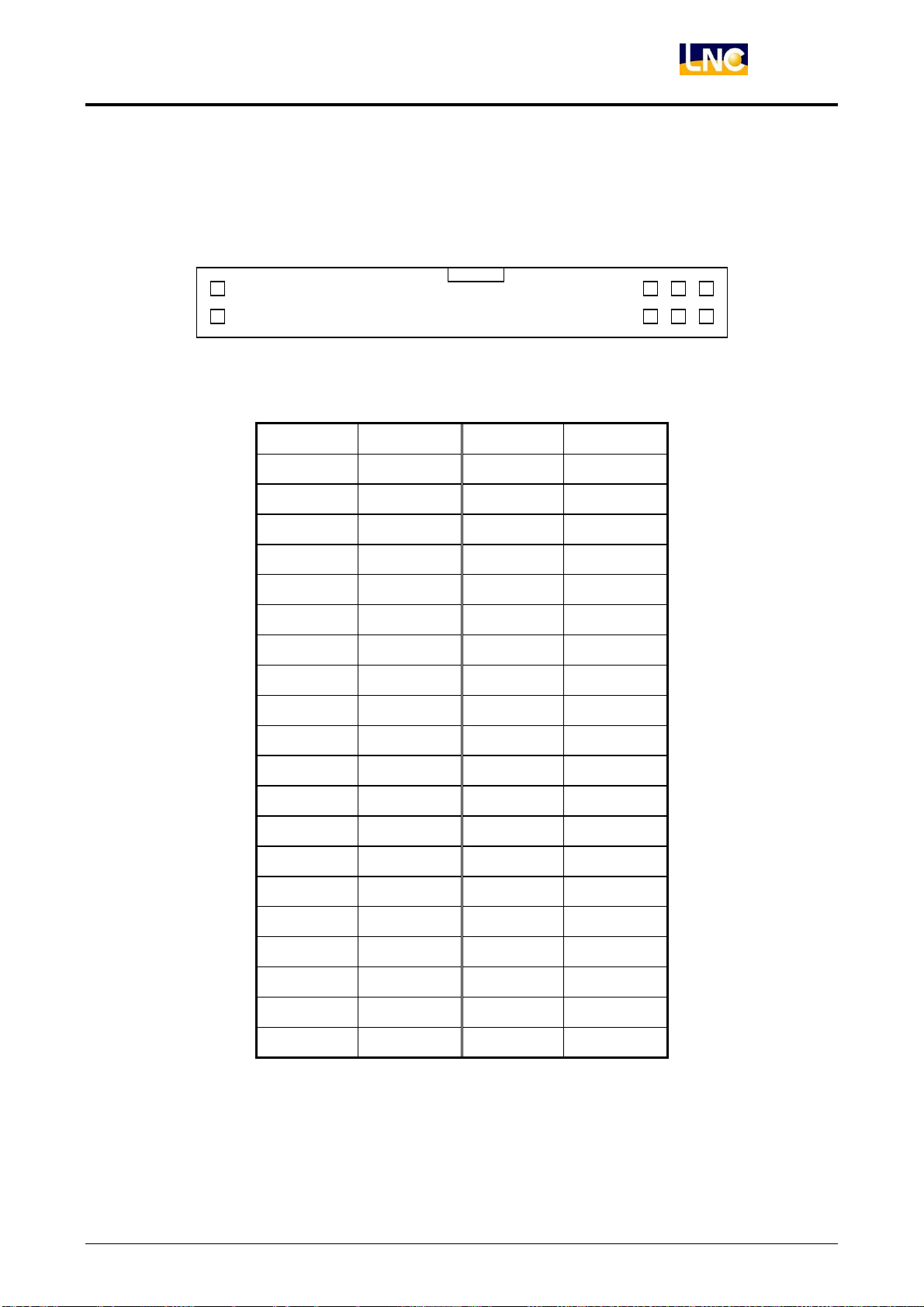
5、PIN DEFINITION
1、D:40PIN 2.54 mm SHROUDED HEADER DEFINITION (OUT00~OUT31,TOTAL 32 PINS)
1
39
………
3
LNC-M600i
40
4
PIN DEFINITION PIN DEFINITION
1
3
5
7
9
11
13
15
17
19
21
23
FG
EGND
OUT 31
OUT 29
OUT 27
OUT 25
OUT 23
OUT 21
OUT 19
OUT 17
OUT 15
OUT 13
2
4
6
8
10
12
14
16
18
20
22
24
FG
EGND
EGND
OUT 30
OUT 28
OUT 26
OUT 24
OUT 22
OUT 20
OUT 18
OUT 16
OUT 14
2
25
27
29
31
33
35
37
39
LNC Technology Co., Ltd. 39
OUT 11
OUT 09
OUT 07
OUT 05
OUT 03
OUT 01
E24V
E24V
26
28
30
32
34
36
38
40
OUT 12
OUT 10
OUT 08
OUT 06
OUT 04
OUT 02
OUT 00
E24V
Page 46
LNC-M600i
Hardware Maintenance
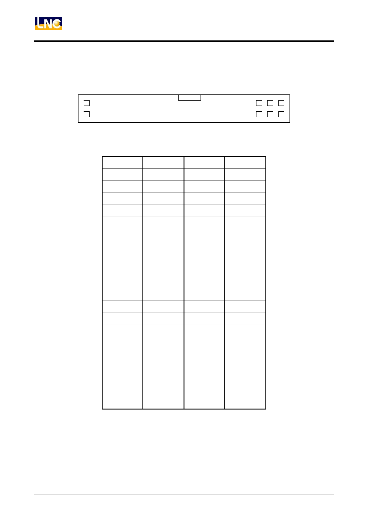
2、E:40PIN 2.54 mm SHROUDED HEADER DEFINITION (IN00~IN39,TOTAL 40 PINS)
39
………
3
1
40
PIN DEFINITION PIN DEFINITION
1
3
5
7
9
11
13
15
17
19
21
23
IN39
IN37
IN35
IN33
IN31
IN29
IN27
IN25
IN23
IN21
IN19
IN17
2
4
6
8
10
12
14
16
18
20
22
24
IN38
IN36
IN34
IN32
IN30
IN28
IN26
IN24
IN22
IN20
IN18
IN16
4
2
25
27
29
31
33
35
37
39
IN15
IN13
IN11
IN09
IN07
IN05
IN03
IN01
26
28
30
32
34
36
38
40
IN14
IN12
IN10
IN08
IN06
IN04
IN02
IN00
40
LNC Technology Co., Ltd.
Page 47
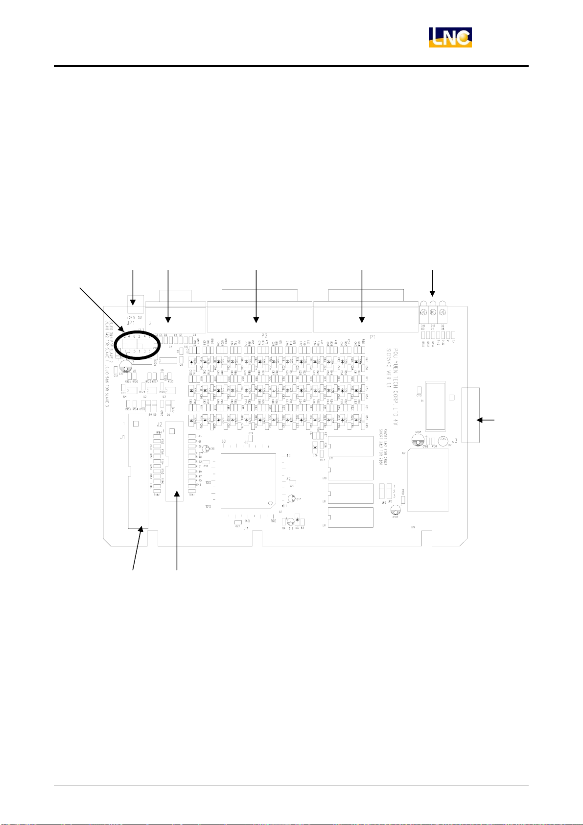
3.4.3 I/O SIO 1540 DEFINITION
3.4.3.1 I/O SPECIFICATION
1、SPECIFICATION:
1、SIO-1540 OFFER 40IN /32 OUT ( OTHER 24IN / 32 OUT OPTION)
2、HARDWARE LAYOUT:
LNC-M600i
Hardware Maintenance
A B
D E
H
I
C
F G
LNC Technology Co., Ltd. 41
Page 48
LNC-M600i
Hardware Maintenance
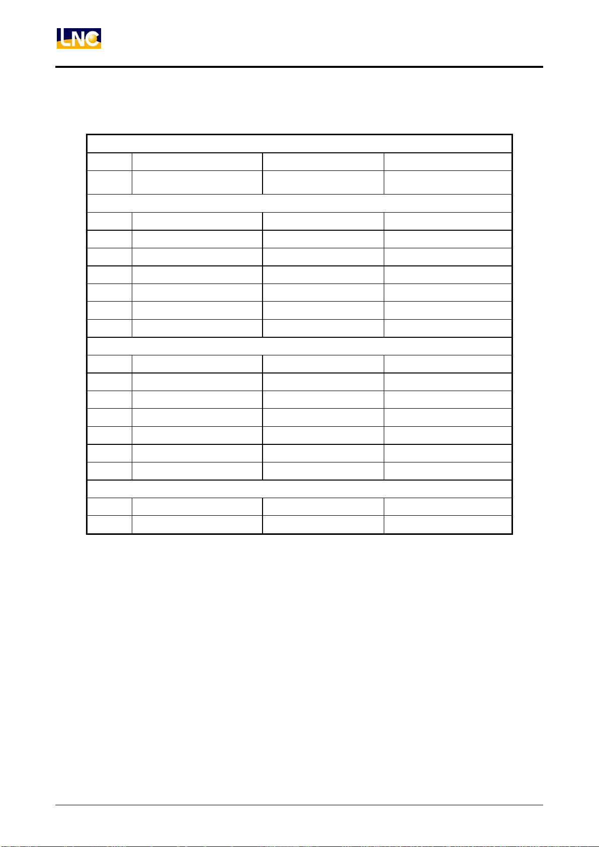
3、CONNECT/OBJECT DESCRIPTION:
POWER
PIC OBJECT TYPE FUNCTION USAGE
A 3PIN 3.81mm head
INDICATOR LIGHT
PIC OBJECT TYPE FUNCTION USAGE
H E5V GREEN LED E5V indicator light E5V normal>ON
E24V GREEN LED E24V indicator light E24V normal>ON
CS YELLOW LED Transmission Light Connect to controller>On
DO YELLOW LED Transmission Light Connect to controller>On
DI YELLOW LED Transmission Light OK>Lights on
LK YELLOW LED Transmission Light OK>Lights on
DC(24V) POWER
INPUT
To P O W E R
IO POINT
PIC OBJECT TYPE FUNCTION USAGE
B D_SUB HD 15PIN Jack Serial Port To Controller RIO
C 16PIN 2.54mm easy head Serial Port To Controller RIO
D D_SUB HD 44PIN Plug Back 20 IN/16 OUT To REL
E D_SUB HD 44PIN Jack Front 20 IN/16 OUT To REL
F 40PIN 2.54 mm easy head Spare 32 O points OPTION
G 26PIN 2.54 mm easy head Spare 24 I points OPTION
SETTING
PIC OBJECT TYPE FUNCTION USAGE
I 2.54mm JUMPER SLAVE number setting Later chapter
42
LNC Technology Co., Ltd.
Page 49
4、Usage、Setting:
A:E24V Power
◎Description:This pin is for O point outpur power, if this pin has problem, O point output will be error.
(Has no effect to IN point)
◎Rated Capacity:E24V±0.5V (3A UP)
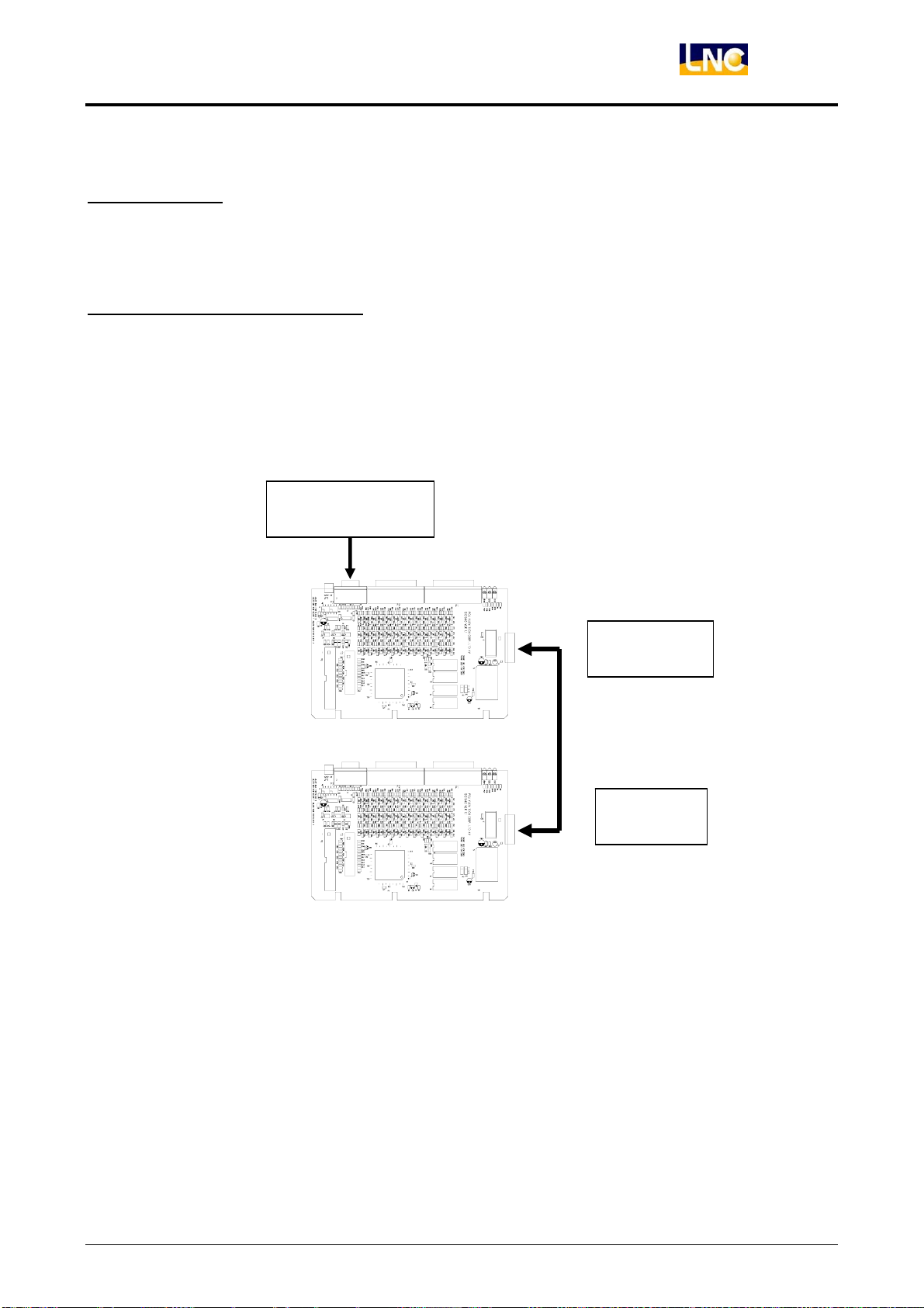
B、C:Serial Transmission Head
◎Description:1.B,C head is for serial connection, need to connect with controller’s RIO port.
2.B,C head is pararell signal, is for serial expansion to use.
◎Serial expansion example:Serial connection for 2 SIO-1520 cards
Controller RIO
LNC-M600i
Hardware Maintenance
(HD 15PIN 1-1 Plug/Plug
Cable)
SLAVE1
( 16 PIN 2.54mm cable)
SLAVE2
LNC Technology Co., Ltd. 43
Page 50
LNC-M600i
Hardware Maintenance
D、E:IO Port
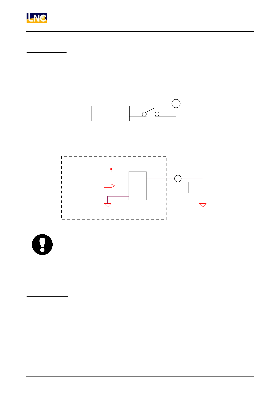
◎Description:1.D、E head connects to REL to do IO controller. Each port can control 20IN/16OUT
tocoordinate with REL board.
◎IN points as below:(REL is not used together)
◎O point direct usage:(REL is not used together)
O type is SOURCE TYPE, motion output is E24V, max voltage is 60mA
E24V
SIO-IN
IO Module
z Please do not make the current more then 60 mA, when doing load selection.
z When O point grounds, if shortcircuit happens, IC will burn out instantly, please
F、G:Spare IO
◎Description:1 F、E head reserve 32OUT/24IN-IO『control interface』, this interface can not be
E24V
OUTPUT
OU T_D ATA
SOURCE TYPE IC
EGND
Otherwise it may have damage to components. E24V/60 mA=400Ω Å Load
resistance can not be less than this value.
pay special attention to is.
LOAD
EGND
44
directly used, need to coordinate with SIO-1530 card.
LNC Technology Co., Ltd.
Page 51
H:Communication/Power Light
◎Description:
(1) E5V Indicator light:when SIO-1520 module connects with controller system, sending power,
indicator light will be ON, that means the module power is complete.
(2) CS、DO Indicator light:If SIO-1520 connect with controller correctly, sending power, CS and DO
will ON. If these two lights didn’t ON at the same time, there may be some errors in it, there will
also have problems after later transmission.
(3) K、DI Indicator light:When CS、DO Indicator light On, If SIO-1540 module’s SLAVE number
setting is the same to PLC setting, LK、DI will ON.
(4) 24V Indicator light:When E24V Indicator light ON, that means the O interface power OK, but if
it’s OFF, O point will not have feedback.
LNC-M600i
Hardware Maintenance
I:SLAVE JUMPER
◎Description:SLAVE number setting, after setting, you need to coordinate with software, PLC plan to
work normally. Please do not change randomly.
◎Setting Example:
1 1
To be SLAVE1,JUMPER Setting
To be SLAVE2,JUMPER Setting
1 1
LNC Technology Co., Ltd. 45
Page 52
LNC-M600i
Hardware Maintenance
5、PIN DEFINITION
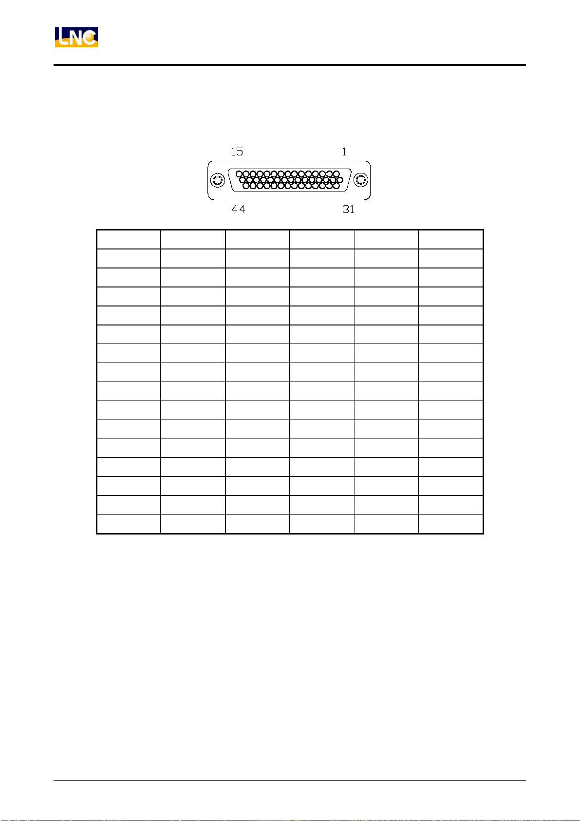
1.E:44 PIN HIGH DENSITY CONNECT(JACK)
PIN DEFINITION PIN DEFINITION PIN DEFINITION
1
2
3
4
5
6
7
8
9
10
11
12
13
14
15
IN 00
IN 03
IN 06
IN 09
IN 12
IN 15
IN 18
OUT 00
OUT 03
OUT 06
OUT 09
OUT 12
OUT 15
-
EGND
16
17
18
19
20
21
22
23
24
25
26
27
28
29
30
IN 01
IN 04
IN 07
IN 10
IN 13
IN 16
IN 19
OUT 01
OUT 04
OUT 07
OUT 10
OUT 13
-
-
EGND
31
32
33
34
35
36
37
38
39
40
41
42
43
44
X
IN 02
IN 05
IN 08
IN 11
IN 14
IN 17
OUT 02
OUT 05
OUT 08
OUT 11
OUT 14
-
E24V
E24V
-
46
LNC Technology Co., Ltd.
Page 53
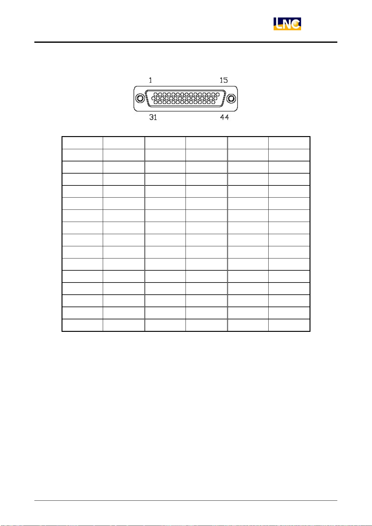
2.D:44 PIN HIGH DENSITY CONNECT(PLUG)
PIN DEFINITION PIN DEFINITION PIN DEFINITION
LNC-M600i
Hardware Maintenance
1
2
3
4
5
6
7
8
9
10
11
12
13
14
15
IN 20
IN 23
IN 26
IN 29
IN 32
IN 35
IN 38
OUT 16
OUT 19
OUT 22
OUT 25
OUT 28
OUT 31
-
EGND
16
17
18
19
20
21
22
23
24
25
26
27
28
29
30
IN 21
IN 24
IN 27
IN 30
IN 33
IN 36
IN 39
OUT 17
OUT 20
OUT 23
OUT 26
OUT 29
-
-
EGND
31
32
33
34
35
36
37
38
39
40
41
42
43
44
-
IN 22
IN 25
IN 28
IN 31
IN 34
IN 37
OUT 18
OUT 21
OUT 24
OUT 27
OUT 30
-
E24V
E24V
-
LNC Technology Co., Ltd. 47
Page 54
LNC-M600i
Hardware Maintenance
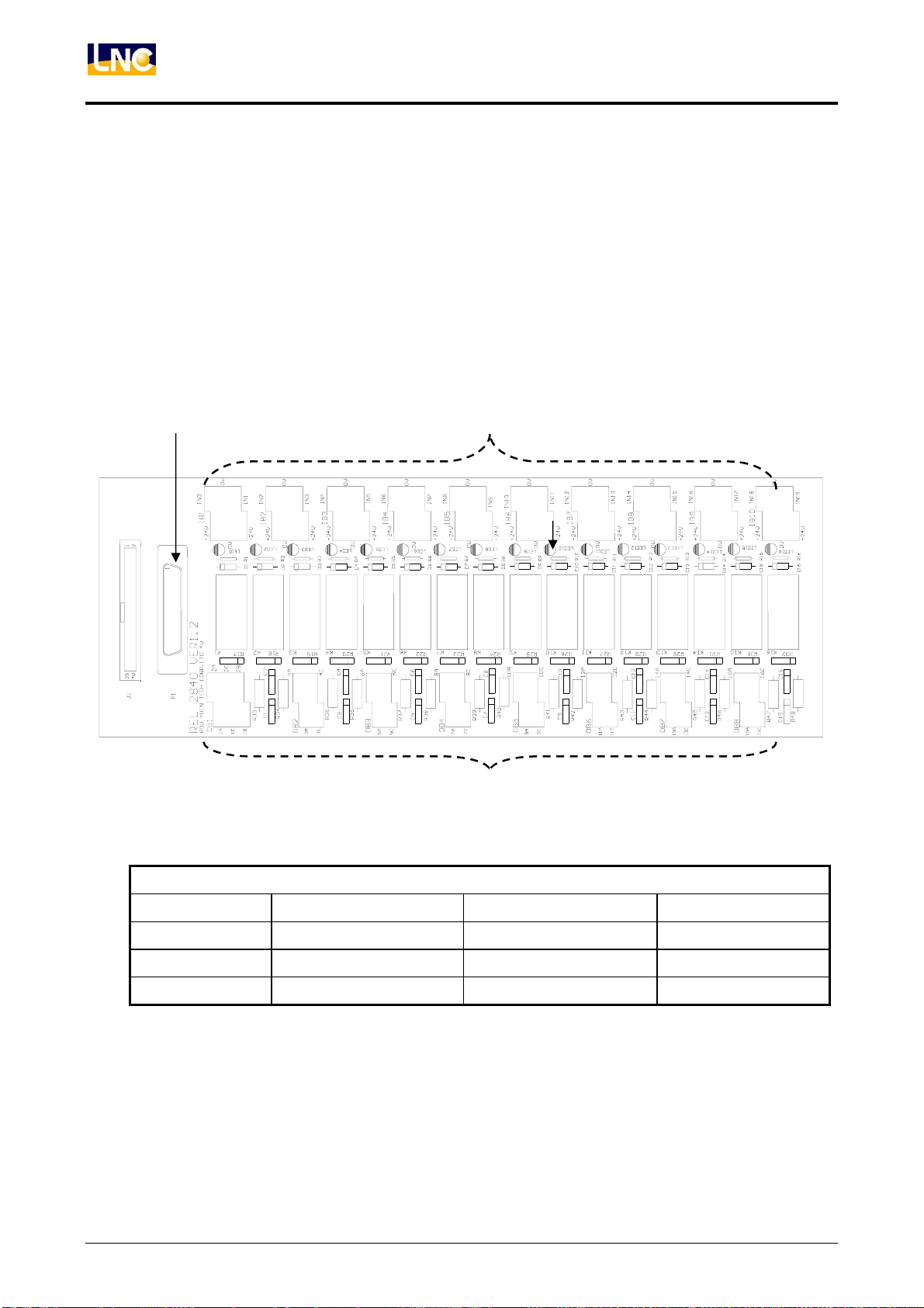
3.4.3.2 REL2840 SPECIFICATION
1.、Specification:
1. Offers 20 IN and E24V/EGND input point with terminal lock.
2. Ouput side offers 2 sets of A、B、C points and 14 sets of A、C points, total to be 16 sets of output points.
3. Ouput point capacity is AC 6A/250V.
2、Hardware Layout:
A B
C
3、Connect and components
IO
Picture Components Function Usage
A D_SUB HD 44PIN Jack 20 IN / 16 OUT SIO
B 5.08mm lock with head IN point To external object
C 5.08mm lock with head OUTpoint To external object
Note 1:B lock with head offers 20 EGND and 20 E24V to use with input points.
Note 2:Every relay has its own corresponding red LED. When relay has magnetizing action, LED will
ON. Users can use this function to find out relay errors.
48
LNC Technology Co., Ltd.
Page 55
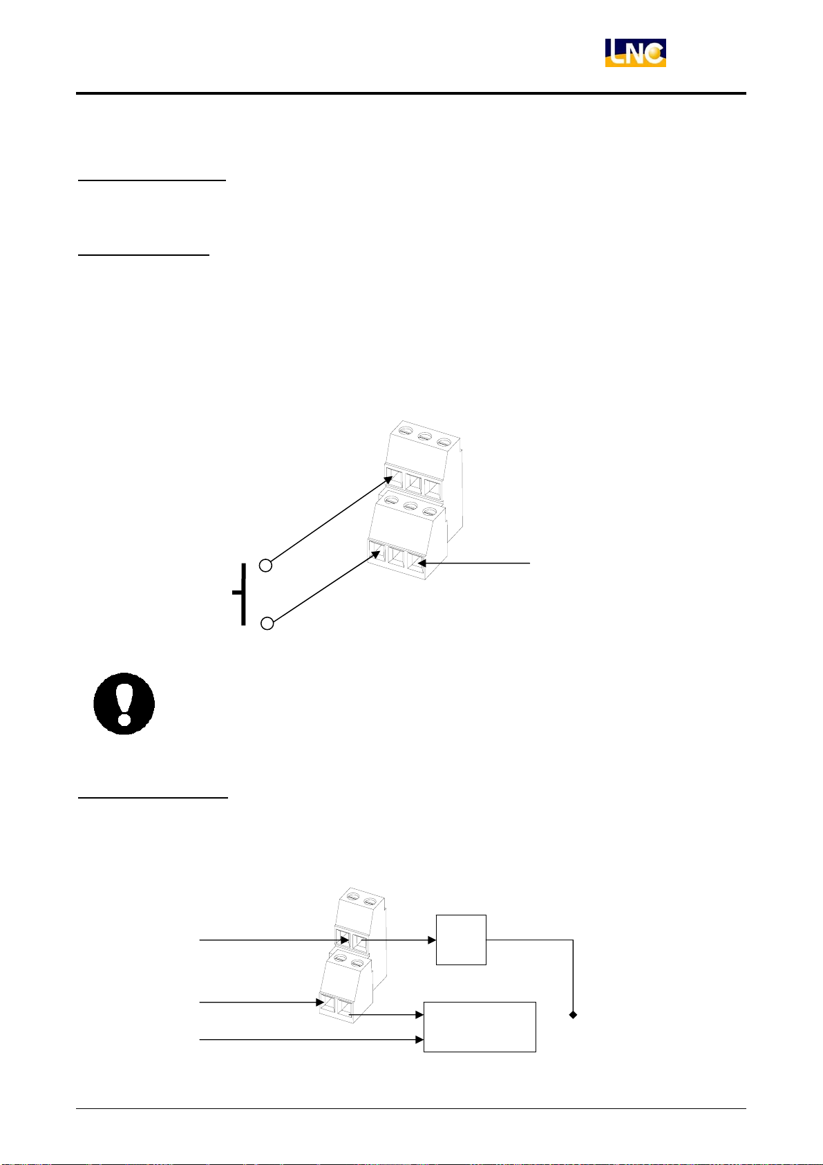
4.、Usage and setting:
A:IO Control Head
◎Description:This head is 20IN/16 OUT IO control head, connects with SIO and EIO.
LNC-M600i
Hardware Maintenance
B:IN Point Head
◎Description:1.IN point signal will be lead in by these connects, via IO control head to lead back to
◎IN points head example:
z Use swith or points
to lead in E24V or
0V(EGND) into IN.
SIO and EIO Module.
2.The E24V and EGND(0V)on the connect were lead by SIO and EIO module via IO
control head to REL-2840.
24V
0V
24V
z E24V input( sensor
IN
0V
IN0
object)
z Use NPN IN, please confirm corresponding SIO and EIO module support NPN
mode.
z Please follow direction to connect, prevent the short circuit of E24V and EGND.
C:OUT Point Head
◎Description:REL-2840 O point head is on RELAY’s A and C, contact capacity is 6A / 250V.
◎OUT points head example:
VEE
AC1
AC0
A
C
load
A
C
Other powers
VEE-GND
LNC Technology Co., Ltd. 49
Page 56
LNC-M600i
Hardware Maintenance
z OUT point is machine points, not suitable for high speed and requent ON / OFF
application.
z Do not connect over point capacity.
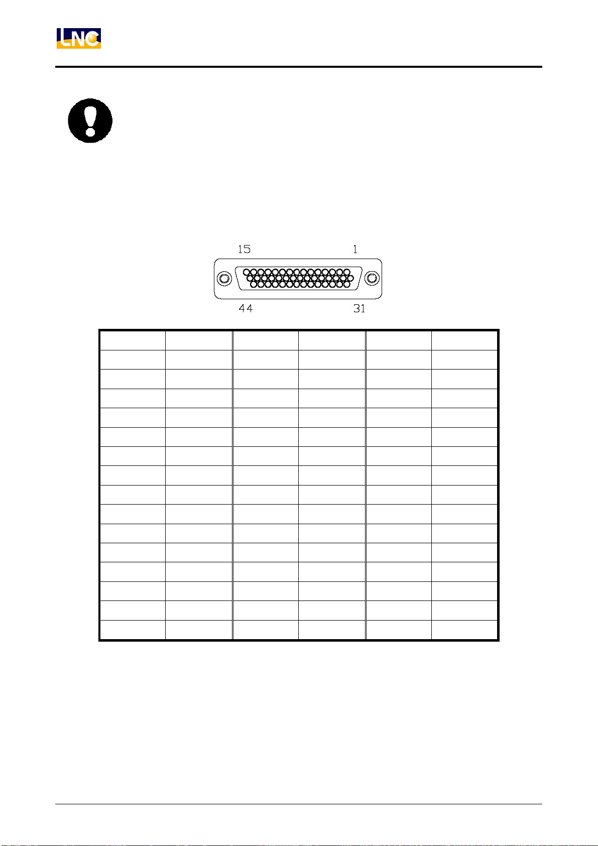
5、PIN DEFINITION:
A:44 PIN HIGH DENSITY CONNECT(JACK)
PIN DEFINITION PIN DEFINITION PIN DEFINITION
1 IN 00 16 IN 01 31 IN 02
2 IN 03 17 IN 04 32 IN 05
3 IN 06 18 IN 07 33 IN 08
4 IN 09 19 IN 10 34 IN 11
5 IN 12 20 IN 13 35 IN 14
6 IN 15 21 IN 16 36 IN 17
7 IN 18 22 IN 19 37 OUT 02
8 OUT 00 23 OUT 01 38 OUT 05
9 OUT 03 24 OUT 04 39 OUT 08
10 OUT 06 25 OUT 07 40 OUT 11
11 OUT 09 26 OUT 10 41 OUT 14
12 OUT 12 27 OUT 13 42 -
13 OUT 15 28 - 43 E24V
14 - 29 - 44 E24V
15 EGND 30 EGND - -
50
LNC Technology Co., Ltd.
Page 57
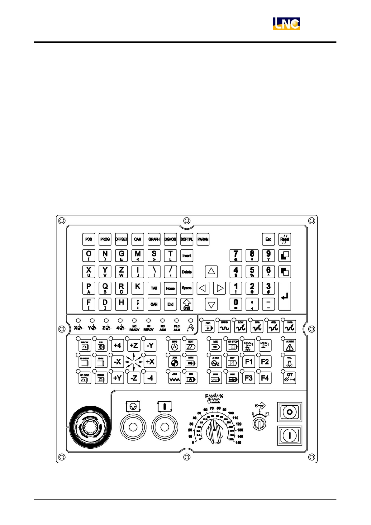
3.4.4 MDIOP8500 OP DESCRIPTION
1、SPECIFICATION:
1.MDI
2.EMG STOP BUTTON
3.CYCLE START/FEED HOLD BUTTON
4.DIAL SWITCH
5.POWER ON、POWER OFF BUTTON
6.BUTTON
7.INPUT POINTS 64 IN (24V STANDARD INPUT)
8.OUTPUT POINTS 50 OUT(24V STANDARD OUTPUT)
2、HARDWARE LAYOUT:
MDIOP8500 FRONT LAYOUT
LNC-M600i
Hardware Maintenance
LNC Technology Co., Ltd. 51
Page 58
LNC-M600i
Hardware Maintenance
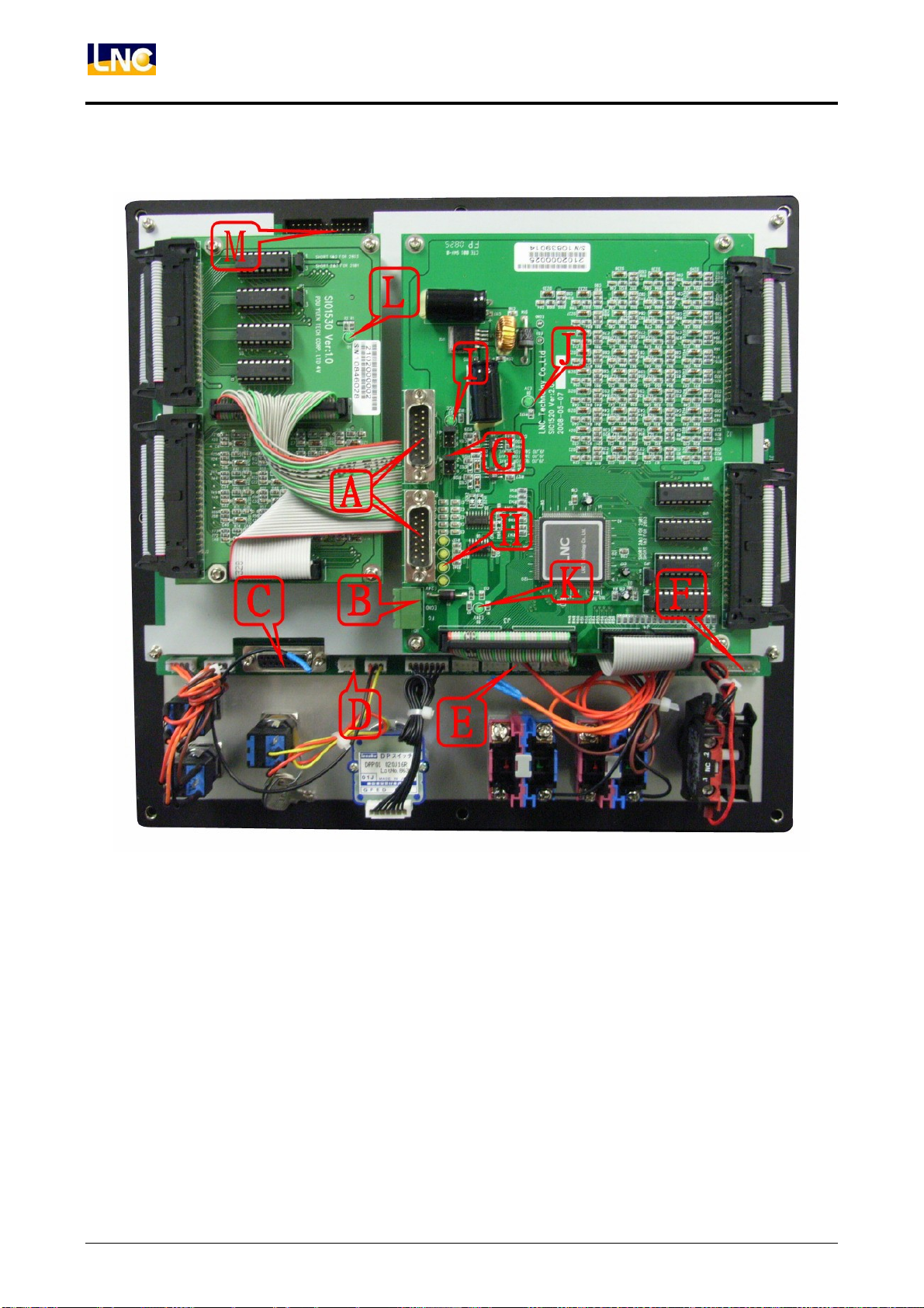
MDIOP8500 BACK VIEW
52
LNC Technology Co., Ltd.
Page 59
3、Connect and components:
IO Control---(A)
Head Type Function Usage
P2 D_SUB 15PIN Plug Serial IO Interface To PCC card
P3 D_SUB 15PIN Plug Serial IO Interface To PCC card
Power---(B)
Head Type Function Usage
JP1 3PIN 5.08mm IO DC 24V /FG To POWER/Case
ON/OFF Control、Safety loop---(C)
Head Type Function Usage
J12 D_SUB 15PIN Jack Power ON/OFF, Safety loop head To TRF(ON/OFF)head
Panel IO---(D)
Head Type Function Usage
J6 3PIN 2.5 mm white head User planning
J7 2PIN 2.5 mm white head KEY
LNC-M600i
Hardware Maintenance
Panel IO---(E)
Head Type Function Usage
J16~J19 4PIN2.5mm white head User planning
J20 2PIN2.5 head User planning
Panel IO---(F)
J15 7PIN2.5mm white head User planning
JUMPER Setting---(G)
Head Type Function Usage
JP9、JP10
3PIN 2.54mm SLAVE setting To 1~3
Indicator Light ---(H、I、J、K、L)
Light Type Function Usage
D7 3.0mm (Green) IO Cable 5V indicator light
D8 3.0mm (Green) SIO1520 E5V indicator light
D9~D12 3.0mm (Yellow) Transmission indicator light
D2 3.0mm (Green) SIO1520 E24V indicator light
D1 3.0mm (Green) SIO1530 E24V indicator light
MDI ---(M)
Head Type Function Usage
MD1 26PIN 2.54 Easy Head MDI To Keyboard
LNC Technology Co., Ltd. 53
Page 60
LNC-M600i
Hardware Maintenance
4、Usage/setting and lights:
A:P2、P3 USAGE
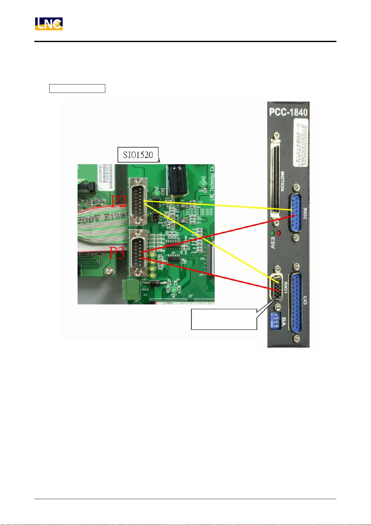
PCC Series motion card RIO Pin
This picture is PCC1840
motion card
If you want this IO on the MDIOP to have feedback, you will need to connect this Pin with PCC card.
NOTICE:As for transmission cable, please refer to accessory 1.
54
LNC Technology Co., Ltd.
Page 61
LNC-M600i
Hardware Maintenance
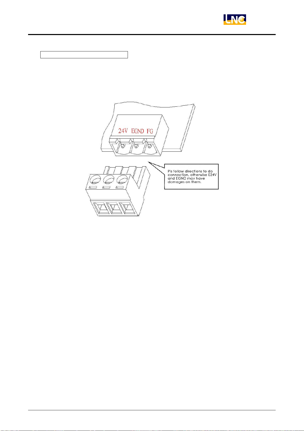
B:JP1--E24V Power Connect Usage
JP1 head offers MDIOP8500’s Output power, O points need to have output and MDIOP needs to lead in
E24V power.
◎Head Description:
E24V and EGND connect to power supply’s DC output, FG to grounding( please connect with chassis
to do grounding )
◎Power demand:E24V(3A UP)
Notice:
1、E24V power input data has relation with MDIOP8500’s O points output. Please consider about the
voltage loss of cable when wiring to make sure later components have enough voltage to work (such
as:the driven RELAY object is 24V, but because of the voltage loss, it turn to be 16V. When doing
output action, RELAY may not workable.)
2、Please use 0.75mm or upper cables for T1 head and power supply and shorter is better.
3、Please do not connect the grounding of 24V power supply to T1‘s FG(grounding) to prevent OP’s
action error or component damage.
LNC Technology Co., Ltd. 55
Page 62
LNC-M600i
Hardware Maintenance
C:J12 ON/OFF Safety Loop Head Usage
J12 head offers ON/OFF and EMG button’s conection port. Users need to connect with TRF board’s
ON/OFF heads( such as TRF1720、TRF2760) and use 15PIN 1 on 1 cables. After connection, it can
control TRF board’s power control RELAY and SERVO_ON RELAY.
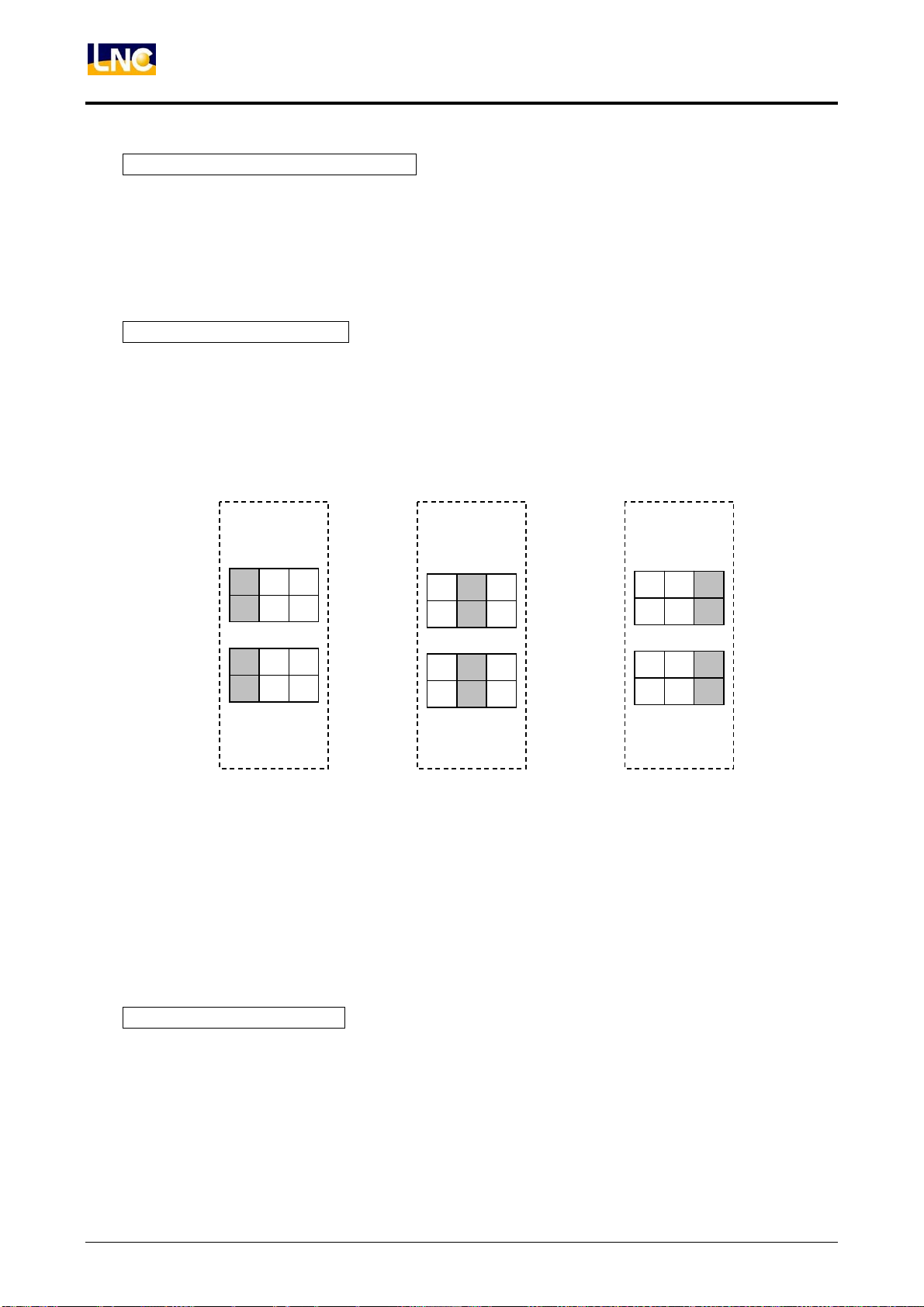
D:JP9、JP10 JUMPER Setting
JUMPER FUNCTION IS AS BELOW:
JP9、JP10:these are for serial connection SLAVE control setting.
JP9、JP10 Setting:
S0 S1 S2
S0 S1 S2
S0 S1 S2
JP9
JP10
S0 S1 S2
Setting to be SLAVE1
S0 S1 S2
Setting to be SLAVE2 Setting to be SLAVE3
S0 S1 S2
(DEFAULT)
Setting Description:
1. Upper colored parts are for JUMPER short circuit position.
2. Hardware and software setting should be the same to software setting.(PLCIO.CGF file), IO can
work correctly.
E:Indicator Lights Description
MDIOP8500 offers 4 indicator lights for easy debug, details are as below:
56
LNC Technology Co., Ltd.
Page 63
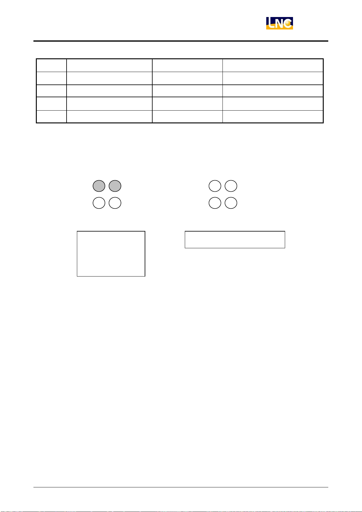
Hardware Maintenance
Indicator Light Description When Lights OFF>NG Exam method
I OP’s 5V OK RIO is NG Confirm RIO cables
J DC/DC OK RIO is NG PCB components Error
K SIO1520’s E24V OK I/O NG Confirm T1 head, E24V power
LNC-M600i
L SIO1520’s E24V OK I/O NG
Confirm J3、J4 connection
INDICATOR LIGHT H:
D10 D9
D10 D9
D8 D7 D8 D7
SystemON>RIO
Transmission OK>D7~D9 ON
OK>D7,D8
ON>D9,D10 OFF
Users can not only use the software alarm to confirm RIO situation, but can also use indicator light H to
judge IO transmission.
Note:Transmission OK (D7~D10 ON) Need condition as below
1 RIO transmissioncable OK(No such error situation, like fail solder, braking cables…and so on)
Transmission cables connect two sidefirmly.
2 F and G two indicator lights ON.
3 JP9、JP10 JUMPER setting is the same to software(PLCIO.CFG file)
4 System program operation.
LNC Technology Co., Ltd. 57
Page 64
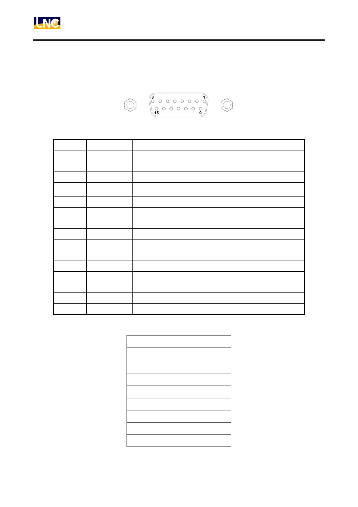
LNC-M600i
Hardware Maintenance
5、Interface and pin definition:
(1) ON/OFF PIN DEFINITION ----ON/OFF、EMG control interface signal
PIN NAME DESCRIPTION
1 OTR1 Overtravel release button point 1
2 × ×
3 × ×
4 SERONL
Servo on indicator light control(light is on OP, control is on
Transit board)
5 EGND E24V Power GND
6 OFF1 OFF button point 1
7 ESP1 EMG button point 1
8 ON1 ON button point 1
9 OTR2 Overtravel release button point 2
10 × ×
11 × ×
12 OFFL OFF button light control
13 OFF2 OFF button point 2
14 ESP2 EMG button point 2
15 ON2 ON button point 2
(2) J15 PIN DEFINITION ---IN Interface Signals
PIN DEFINITION
1 IN48
2 IN50
3 ×
4 E24V
5 IN51
6 IN49
7 ×
58
J15
LNC Technology Co., Ltd.
Page 65
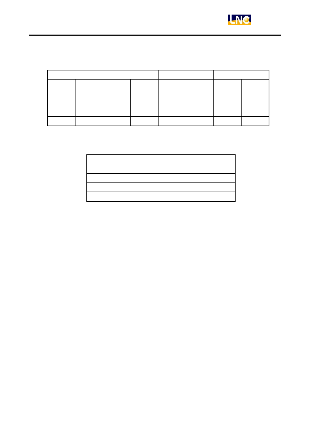
(3) J16、J17、J18、J19 PIN DEFINITION ---IN Interface signals
J16 J17 J18 J19
1 IN54 1 IN58 1 IN56 1 IN60
2 IN53 2 IN57 2 IN55 2 IN59
3 IN54 3 IN58 3 IN56 3 IN60
4 EGND 4 EGND 4 EGND 4 EGND
(4) J6 PIN DEFINITION
J6
PIN DEFINITION
LNC-M600i
Hardware Maintenance
1 IN06
2 IN07
3 24V
LNC Technology Co., Ltd. 59
Page 66
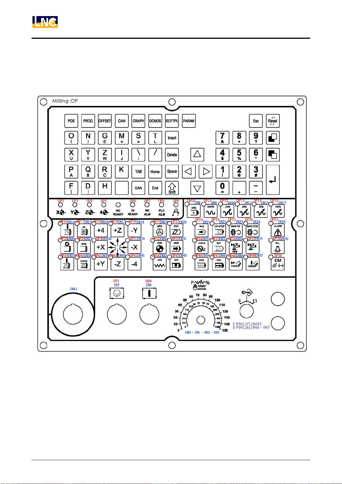
LNC-M600i
Hardware Maintenance
6、MDIOP8500 OPERATION IO PLAN CHART:
Description:Below IO numbers is the corresponding hardware IO point.
Example:IN1 means this point is the first IN point on SIO1520 card.
60
LNC Technology Co., Ltd.
Page 67
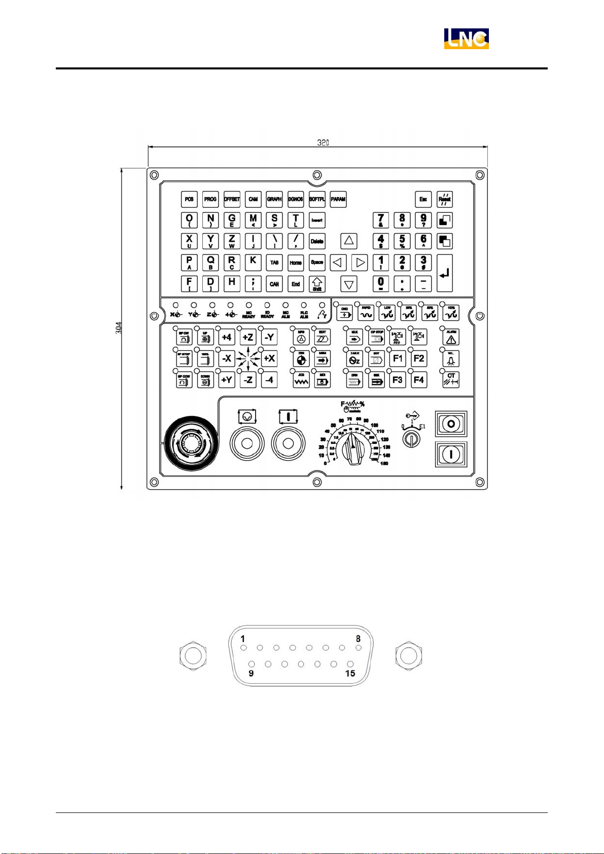
7、Size Dimension:
LNC-M600i
Hardware Maintenance
Accessory:Transmission cable info
1 Cable 1 to 1.
2 Please kindly use set pair cable.
3 Please make sure to do grounding.
LNC Technology Co., Ltd. 61
Page 68
LNC-M600i
PLC Maintenance -- C,S Bits and Register
4 PLC Maintenance -- C,S Bits and Register
4.1 C Bits Definition
C BIT PLCÆCNC
BIT # SYMBOL Description Pagination
000 ST Cycle Start
001 SP Feed Hold
003 PPROT Prog Protect
004 MANRET Manual Return
006 +X +X Axis Direction
007 -X -X Axis Direction
008 +Y +Y Axis Direction
009 -Y -Y Axis Direction
010 +Z +Z Axis Direction
011 -Z -Z Axis Direction
012 +4 +4 Axis Direction
013 -4 -4 Axis Direction
016 HX Handle X Axis
017 HY Handle Y Axis
018 HZ Handle Z Axis
019 H4 Handle 4th Axis
020 MPGDRN MPG Dry Run
021 SCNSAV Wake up the screen saver signal
023 RT Rapid
031 HOMEX X Axis Home DOG Signal
032 HOMEY Y Axis Home DOG Signal
033 HOMEZ Z Axis Home DOG Signal
034 HOME4 4th Axis Home DOG Signal
036 ESP Emergency Stop
037 ERS External Reset
038 FIN M, S, T Finish
040 SBK Single Block
041 BDT Optional Block Skip
042 DRN Dry Run
043 MLK Machine Lock
044 OPS Optional Stop
045 ZNG Z Axis Cancel
046 AFL Auxiliary Function Lock
049 4NG 4th Axis Neglect
050 +LX +X Axis OT
051 -LX -X Axis OT
052 +LY +Y Axis OT
053 -LY -Y Axis OT
054 +LZ +Z Axis OT
055 -LZ -Z Axis OT
056 +L4 +4th Axis OT
057 -L4 -4th Axis OT
059 INTLKX X Axis Interlock
060 INTLKY Y Axis Interlock
061 INTLKZ Z Axis Interlock
062 INTLK4 4th Axis Interlock
064 WINRW PLC Window Read/Write Signal
065 WINREQ PLC Commanding Signal
68
68
68
68
69
69
69
69
69
69
69
69
69
69
69
69
69
69
69
70
70
70
70
70
70
70
71
71
71
71
71
71
71
71
72
72
72
72
72
72
72
72
73
73
73
73
79
79
62
LNC Technology Co., Ltd.
Page 69
LNC-M600i
PLC Maintenance -- C,S Bits and Register
BIT # SYMBOL Description Pagination
066 HIX X Axis: Select Axis Direction Signal of Handle INT
067 HIY Y Axis: Select Axis Direction Signal of Handle INT
068 HIZ Z Axis: Select Axis Direction Signal of Handle INT
069 HI4 4th Axis: Select Axis Direction Signal of Handle INT
075 SVAX X Axis Servo Alarm
076 SVAY Y Axis Servo Alarm
077 SVAZ Z Axis Servo Alarm
078 SVA4 4th Axis Servo Alarm
082 S1CW 1st Spindle CW
083 S1CCW 1st Spindle CCW
085 ORT Spindle Orientation
086 SPPULF Spindle Command Type Changes to Pulse Type Under Spindle
Orientation and Ridig Tapping Modes
089 MRX X Axis Mirror Image
090 MRY Y Axis Servo Alarm
091 MRZ Z Axis Servo Alarm
092 MR4 4th Axis Servo Alarm
097 S1GR1 1st Spindle Gear #1
098 S1GR2 1st Spindle Gear #2
099 S1GR3 1st Spindle Gear #3
100 UI0 MACRO Variable $200
101 UI1 MACRO Variable $201
102 UI2 MACRO Variable $202
103 UI3 MACRO Variable $203
104 UI4 MACRO Variable $204
105 UI5 MACRO Variable $205
106 UI6 MACRO Variable $206
107 UI7 MACRO Variable $207
108 UI8 MACRO Variable $208
109 UI9 MACRO Variable $209
110 UI10 MACRO Variable $210
111 UI11 MACRO Variable $211
112 UI12 MACRO Variable $212
113 UI13 MACRO Variable $213
114 UI14 MACRO Variable $214
115 UI15 MACRO Variable $215
119 ZP2ZDC ZP2Z Down Cancel
120 PMCGO PMC Axis Go
124 RTFIN Disable Sigal in Rigid Tapping
125 RTST Enable Signal in Rigid Tapping
126 SWEN Enable Signal of Spindle Motor Rotates in Gear-Shfiting Speed
127 SWFIN Spindle Gear-Shifting Complete Signal
134 PRTCLR Clear Working Piece Number
140 2NDSLX 2nd +X Axis Software Limit Choice
141 2NDSLX 2nd -X Axis Software Limit Choice
142 2NDSLY 2nd +Y Axis Software Limit Choice
143 2NDSLY 2nd -Y Axis Software Limit Choice
144 2NDSLZ 2nd +Z Axis Software Limit Choice
145 2NDSLZ 2nd -Y Axis Software Limit Choice
146 2NDSL4 2nd +4th Axis Software Limit Choice
147 2NDSL4 2nd -4th Axis Software Limit Choice
201 AERSTX Absolute encoder Reset Ready Signal:X Axis
202 AERSTY Absolute encoder Reset Ready Signal:Y Axis
203 AERSTZ Absolute encoder Reset Ready Signal:Z Axis
204 AERST4 Absolute encoder Reset Ready Signal:4th Axis
207 AERDYX Absolute Encoder Data Ready Signal:X Axis
73
73
73
73
73
73
73
73
74
74
74
74
74
74
74
74
75
75
75
76
76
76
76
76
76
76
76
76
76
76
76
76
76
76
76
76
76
76
76
76
77
77
77
77
77
77
77
77
77
77
78
78
78
78
78
LNC Technology Co., Ltd. 63
Page 70

LNC-M600i
PLC Maintenance -- C,S Bits and Register
BIT # SYMBOL Description Pagination
208 AERDYY Absolute Encoder Data Ready Signal:Y Axis
209 AERDYZ Absolute Encoder Data Ready Signal:Z Axis
210 AERDY4 Absolute Encoder Data Ready Signal:4th Axis
213 AEB0X Absolute Encoder Data Bit 0Transmitting Signal : X Axis
214 AEB0Y Absolute Encoder Data Bit 0Transmitting Signal : Y Axis
215 AEB0Z Absolute Encoder Data Bit 0Transmitting Signal : Z Axis
216 AEB04 Absolute Encoder Data Bit 0Transmitting Signal : 4th Axis
219 AEB1X Absolute Encoder Bit 1 Transmit: X Axis
220 AEB1Y Absolute Encoder Bit 1 Transmit: Y Axis
221 AEB1Z Absolute Encoder Bit 1 Transmit: Z Axis
222 AEB14 Absolute Encoder Bit 1 Transmit: 4th Axis
78
78
78
79
79
79
79
79
79
79
79
64
LNC Technology Co., Ltd.
Page 71
LNC-M600i
PLC Maintenance -- C,S Bits and Register
4.2 S Bits Definition
S BIT CNCÆPLC
BIT # SYMBOL Description Pagination
000 STL Cycle Start Light
001 SPL Feed Hold Light
002 EDITL Edit Mode Light
003 MEML MEM Mode Light
004 MDIL MDI Mode Light
005 JOGL JOG Mode Light
006 INCJOG INC JOG Mode Light
007 MPGL MPG Mode Light
008 HOMEL Home Mode Light
010 MREADY Preparation Completed
011 MDIPRS MDI keyboard press signal
016 ZP1X X 1st Axis Point Return End
017 ZP1Y Y 1st Axis Point Return End
018 ZP1Z Z 1st Axis Point Return End
019 ZP14 4th 1st Axis Point Return End
020 ZP2X X 2nd Axis Point Return End
021 ZP2Y Y 2nd Axis Point Return End
022 ZP2Z Z 2nd Axis Point Return End
023 ZP24 4th 2nd Axis Point Return End
028 WRN Warning
029 MF M Code Read
030 DEN Distribution EndAlarm
031 AL Alarm
032 RST Reset
033 NCRDY NC Ready
035 X1000 MPG x1000 Ratio Speeding
036 X1 MPG x1 Ratio Speeding
037 X10 MPG x10 Ratio Speeding
038 X100 MPG x100 Ratio Speeding
039 PROGST Program Restart
040 SBKL Single Block
041 BDTL Optional Block Skip
042 DRNL Dry Run
043 MLKL Machine Lock
044 OPSL Optional Stop
045 RTL Rapid Traverse
046 ZNGL Z-Axis Neglect
047 AFLL Auxiliary Function Lock
054 S1STB S Code Read
061 SK2 Z-Axis Neglect
062 SK3 MPG Dry Run
063 SK4 Auxiliary Function Lock
068 MPGDRN MPG Dry Run
069 TSTB T Code Read
071 SK6 Machine Lock
072 SK7 Dry Run
073 SK8 Optional Block Skip
074 SK9 Optional Stop
079 MLCFN PLC Window Finish
080 M00 M00 Read
80
80
80
80
80
80
80
80
80
80
80
80
80
80
80
80
80
80
80
81
81
81
81
81
81
81
81
81
81
81
82
82
82
82
82
82
82
82
82
83
83
83
84
84
84
84
85
85
88
85
LNC Technology Co., Ltd. 65
Page 72
LNC-M600i
PLC Maintenance -- C,S Bits and Register
BIT # SYMBOL Description Pagination
081 M01 M01 Read
082 M02 M02 Read
083 M30 M30 Read
086 ORTFIN Orientation Finish
088 S1SA 1st Spindle Speed Arrival
091 G80 Not in Canned Cycle Mode
092 S1ZSA Spindle Zero Speed Arrival
093 PLSCR Spindle Command Type Changes to Pulse Command in Spindle and
Ridig Tapping Mode
094 GRCAR Spindle Motor Speed when Gears are Switched
100 UO0 MACRO Variable $600
101 UO1 MACRO Variable $601
102 UO2 MACRO Variable $602
103 UO3 MACRO Variable $603
104 UO4 MACRO Variable $604
105 UO5 MACRO Variable $605
106 UO6 MACRO Variable $606
109 UO9 MACRO Variable $609
112 UO12 MACRO Variable $612
113 UO13 MACRO Variable $613
114 UO14 MACRO Variable $614
115 UO15 MACRO Variable $615
120 PMCFIN PMC Axis Finish
128 RTMODE Riding Tapping Mode
130 MOVX X Axis Moving
131 MOVY Y Axis Moving
132 MOVZ Z Axis Moving
133 MOV4 4th Axis Moving
134 WPARV Max Working Piece Arrival
150 SGRC1 Request Signal of Spindle Gear-Shifting: 1st Gear
151 SGRC2 Request Signal of Spindle Gear-Shifting: 2nd Gear
152 SGRC3 Request Signal of Spindle Gear-Shifting: 3rd Gear
153 SGRC4 Request Signal of Spindle Gear-Shifting: 4th Gear
154 MOVDX X Axis Moving Direction
155 MOVDX Y Axis Moving Direction
156 MOVDX Z Axis Moving Direction
157 MOVDX 4th Axis Moving Direction
158 MOVDX 5th Axis Moving Direction
159 MOVDX 6th Axis Moving Direction
201 AETFX Enter into Absolute Encoder Data Transmitting Mode:X Axis
202 AETFY Enter into Absolute Encoder Data Transmitting Mode:Y Axis
203 AETFZ Enter into Absolute Encoder Data Transmitting Mode:Z Axis
204 AETF4 Enter into Absolute Encoder Data Transmitting Mode:4th Axis
207 AETFRX Absolute Encoder Data Transmitting:X Axis
208 AETFRY Absolute Encoder Data Transmitting:Y Axis
209 AETFRZ Absolute Encoder Data Transmitting:Z Axis
210 AETFR4 Absolute Encoder Data Transmitting:4th Axis
213 AERSTX Absolute Encoder Reset:X Axis
214 AERSTY Absolute Encoder Reset:Y Axis
215 AERSTZ Absolute Encoder Reset:Z Axis
216 AERST4 Absolute Encoder Reset:4th Axis
85
85
85
85
86
86
86
86
86
86
86
86
86
86
86
86
86
86
86
86
86
86
86
87
87
87
87
87
87
87
87
87
88
88
88
88
88
88
88
88
88
88
88
88
88
88
88
88
88
88
66
LNC Technology Co., Ltd.
Page 73
LNC-M600i
PLC Maintenance -- C,S Bits and Register
4.3 Register Definition
REGISTER
BIT # SYMBOL Description Pagination
001 M_CODE M0~M99, M Code Command
002 S_CODE S000~S9999, S Code Command
003 T_CODE T000~T9999, T Code Command
004 SPAS Spindle Actual Speed
013 OPMDOE Mode Select
014 INCFED MPG Ratio Select
015 SPDOV Spindle Rotaing Mode Override
016 FEEDOV ATC Mode Feedrate Override
017 JOGOV JOG Mode Feedrate Override
018 RTOV Rapid Traverse Mode Feedrate Override
021 PMCF PMC Feedrate
022 PMCC PMC Control
024 PMCXMM PMC Function of X-Axis Command Amount, Unit=mm
025 PMCXUM PMC Function of X-Axis Command Amount, Unit=um
026 PMCYMM PMC Function of Y-Axis Command Amount, Unit=mm
027 PMCYUM PMC Function of Y-Axis Command Amount, Unit=um
028 PMCZMM PMC Function of Z-Axis Command Amount, Unit=mm
029 PMCZUM PMC Function of Z-Axis Command Amount, Unit=um
030 PMC4MM PMC Function of 4th-Axis Command Amount, Unit=mm
031 PMC4UM PMC Function of 4th-Axis Command Amount, Unit=um
040 OPMES1 PLC Alarm Message
041 OPMES2 PLC Alarm Message
042 OPMES3 PLC Alarm Message
043 OPMES4 PLC Alarm Message
044 OPMES5 PLC Alarm Message
045 OPMES6 PLC Alarm Message
060 MLCFN PLC Windows Function for Item Code
061 MLCSF1 PLC Windows Function for Sub Item Code 1
062 MLCSF2 PLC Windows Function for Sub Item Code 2
063 MLCD1 NC Overwrited PLC Window Function 1
064 MLCD2 NC Overwrited PLC Window Function 2
065 MLCD3 NC Overwrited PLC Window Function 3
066 MLCD4 NC Overwrited PLC Window Function 4
067 MLCD5 NC Overwrited PLC Window Function 5
068 MLCD6 NC Overwrited PLC Window Function 6
069 MLCD7 NC Overwrited PLC Window Function 7
070 MLCD8 NC Overwrited PLC Window Function 8
071 MLCD9 NC Overwrited PLC Window Function 9
072 MLCD10 NC Overwrited PLC Window Function 10
073 MLCD11 NC Overwrited PLC Window Function 11
074 MLCD12 NC Overwrited PLC Window Function 12
89
89
89
89
89
90
90
91
92
93
93
93
93
93
93
93
93
93
93
93
94
94
94
94
94
94
94
94
94
94
94
94
94
94
94
94
94
94
94
94
94
LNC Technology Co., Ltd. 67
Page 74
LNC-M600i
A
A
PLC Maintenance -- C,S Bits and Register
4.4 C Bits Description
C Bit 000
Description:
C Bit 001
Description: Assumed the system is in MEM or MDI mode and also in【NC Ready】 conditions. When this
C Bit 003
Description:
C Bit 004
Description:
Cycle Start
ssumed the system is under MEM or MDI mode. When the signal changes from OFF to On,
the system will be ready to be【Cycle Start】 condition. Meanwhile, the S BIT 000 signal will be
set to ON in order to provide LADDER to enable work light ON function during machine
running. On the other hand, assumed system is in【F-HOLD】 or 【B-STOP】 condition, the S
BIT 000 will be set to OFF in order to provide LADDER to enable work light OFF function during
machine stop. However, this signal will not be accepted by the system under the below three
conditions:
a. System is not under MEM or MDI mode.
b. System is in 【NC NOT Ready】 or 【Cycle Start】 condition.
c. System alarm occurs.
Feed Hold
signal is ON, the system will be in 【F-HOLD】 condition. Meanwhile, the system will set S BIT
000 signal to OFF in order to provide LADDER to enable work light OFF function during
machine running. And also, to set S BIT 001 signal to ON in order to provide LADDER to
enable work light ON function during machine stop. But, please notice that this signal is
disabled (ineffective) for PMC axis function under JOG or RAPID mode.
Prog Protect
When this signal is set to ON, part program editing is prohibited.
Manual Return
ssumed NC is under MEM or MDI mode. If switching to JOG or MPG mode during program
executing and also manual moves the machine away from the original program interrupting
position, user can have the following two selections to continue the unfinished command:
1. Manual Return: Moving the machine back to the original program interrupting position first
and then to continue the unfinished commanding.
2. Continue the unfinished commanding from the current position. But, there will be a
OFFSET amount of coordinate.
68
LNC Technology Co., Ltd.
Page 75
A
A
C Bit 006
C Bit 007
C Bit 008
C Bit 009
C Bit 010
C Bit 011
C Bit 012
C Bit 013
Description:
C Bit 016
C Bit 017
C Bit 018
C Bit 019
Description:
C Bit 020
Description:
C Bit 021
Description:
C Bit 023
Description:
LNC-M600i
PLC Maintenance -- C,S Bits and Register
+X Axis Direction
-X Axis Direction
+Y Axis Direction
-Y Axis Direction
+Z Axis Direction
-Z Axis Direction
+4 Axis Direction
-4 Axis Direction
These signals are selection commanding of system relative axis direction. There are three
corresponding motions under each mode:
a. JOG Mode:
When axis direction signal is ON, the system will send out commanding signal to the
designated axis direction in JOG speed until the signal is OFF.
b. RAPID Mode:
When axis direction signal is ON, the system will send out commanding signal to the
designated axis direction in RAPID speed until the signal is OFF.
c. HOME:
When axis direction signal changes from OFF to ON, it starts moving back to HOME.
Handle X Axis
Handle Y Axis
Handle Z Axis
Handle 4th Axis
These signals are used under MPG mode, which are to indicate the present select servo axis.
For example, if C BIT 016 signal is ON, it indicates that the present MPG axis direction is X
axis. So, turning the MPG rotary switch will moving the servo axis toward X axis.
HX:X Axis MPG Feed
HY:Y Axis MPG Feed
HZ:Z Axis MPG Feed
th
H4:4
MPG Dry Run
So, when operator uses MPG, the axis is moving in original feedrate, otherwise, stop.
Wake up the screen saver signal
The signal which is used by PLC to notify system stopping screen saver and recount start-time.
Rapid
equal to RAPID mode. So, operator can apply the same principle in HOME mode.
Axis MPG Feed
ssumed the NC is in MEM or MDI mode. When this signal is ON, MPG is as feederate control.
ssumed NC is in JOG mode. If RT signal is ON, feedrate becomes rapidly speed, which is
LNC Technology Co., Ltd. 69
Page 76
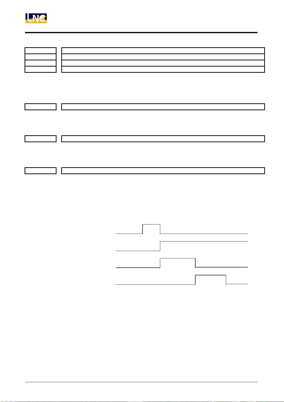
LNC-M600i
A
PLC Maintenance -- C,S Bits and Register
C Bit 031
C Bit 032
C Bit 033
C Bit 034
Description:
C Bit 036
Description:
C Bit 037
Description:
C Bit 038
Description:
X Axis Home DOG Signal
Y Axis Home DOG Signal
Z Axis Home DOG Signal
4th Axis Home DOG Signal
To notify NC the present HOME DOG signal.
Remark: When Parameter # 0175 is 1 and when HOME DOG uses REMOTE key-in point, this
signal is enabled.
Emergency Stop
When this signal is ON, the system is in RESET condition and all motions stop, which means
the system condition is NOT READY.
External Reset
System outer RESET signal which is the same function as pressing RESET bottom.
M, S, T Finish
ssumed NC is in the MEM or MDI mode. When the program executes M code interpretation,
the content of M Code will be sent by REG 1. At the same time, it will send out M Code Read
(MF)signal.
When LADDER finishes executing the related M Code and replies it back to M,S,T Finish
(FIN)signal, the signal will inform the system that the executing of M code is completed.
Correct order is as following:
M CODE INTERPREATION
REG
MF
FIN
a. When executing M77, 77 will be entered into REG 1.
b. Assumed M Code and motion command are in the same BLOCK. If want M Code to
execute its command after motion command is completed, then m code must coordinate
with Distribution End(DEN)command under LADDER control.
c. M00, M01, M02, M30, M98, M99 has no such simultaneous motion.
70
LNC Technology Co., Ltd.
Page 77

LNC-M600i
A
A
A
A
PLC Maintenance -- C,S Bits and Register
C Bit 040
Description:
C Bit 041
Description: Assumed NC is in auto-executing of MEM mode. If there is a such symbol, “/”, in a program,
C Bit 042
Description:
C Bit 043
Description:
C Bit 044
Description:
C Bit 045
Description:
C Bit 046
Description:
C Bit 049
Description:
Single Block
Assumed NC is in auto-executing condition of MEM mode. If this signal is ON, the system will
stop after a BLOCK of program is finish executing. But, if STL signal in OFF and system
condition is B_STOP, then NC will start executing the next BLOCK of program after Cycle Start
(ST) signal is ON.
Optional Block Skip
any key-in after this symbol to EOB will be neglected.
Dry Run
ssumed NC is in MEM or MDI mode. If this signal is ON, program will be executed under the
below feedrates:
G00:When RT is ON = RAPID feed.
When RT is OFF =JOG feed.
G01:JOG feed.
Machine Lock
ssumed NC is under manual and auto modes, all moving command will NOT send to position
control servo system. But, software interpolation value is still executed which means that
program coordinate will still be renewed.
Optional Stop
ssumed this signal is ON. If program executing reaches M01, system will be paused and STL
signal is OFF. This implies that the system will continue executing programs after pressing
Cycle Start (ST) bottom.
Z Axis Cancel
ssumed NC is in manual and auto modes. If this signal is ON, Z axis will be locked, which
means that Z axis moving command will NOT be sent to loop control servo system. But, Z axis
software interpolation value is still executing. So, program coordinate will be renewed.
Auxiliary Function Lock
Assumed this signal is ON. When M, S and T codes are executing, content code and reading
signal are not sending out which means not to execute M, S and T simultaneously.
4th Axis Neglect
When this signal is ON, the corresponding axis commanding will NOT be executed.
For example: Enable 4
th
axis neglect which means when executing part program G01 X10 Z10
C10, C10 commanding will be neglected.
LNC Technology Co., Ltd. 71
Page 78
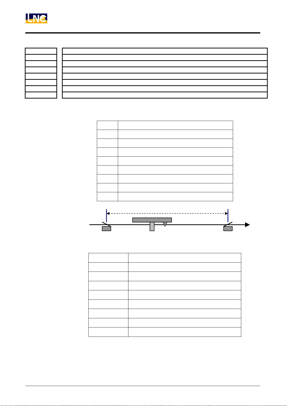
LNC-M600i
g
PLC Maintenance -- C,S Bits and Register
C Bit 050
C Bit 051
C Bit 052
C Bit 053
C Bit 054
C Bit 055
C Bit 056
C Bit 057
Description:
+X Axis OT
-X Axis OT
+Y Axis OT
-Y Axis OT
+Z Axis OT
-Z Axis OT
+4th Axis OT
-4th Axis OT
Each axis sends out the machine hardware-traveling signal in order to inform the system to
display it. These C Bits are PLC travel limit signals for each axis. When these C BIT signals are
on, the system alarm will be enabled. So the servo axis can only move toward the opposite
direction. The following list is the definition for each C BIT:
C BIT Definition
50 X Axis +ive direction PLC Travel Limit
51 X Axis -ive direction PLC Travel Limit
52 Y Axis +ive direction PLC Travel Limit
53 Y Axis -ive direction PLC Travel Limit
54 Z Axis +ive direction PLC Travel Limit
55 Z Axis -ive direction PLC Travel Limit
56 4th Axis +ive direction PLC Travel Limit
57 4th Axis -ive direction PLC Travel Limit
X axis movin
Enable C51
direction
The following list is the warning message of PLC travel limit:
WARNING ID
OP 6001
OP 6002
OP 6003
OP 6004
OP 6005
Warning Message
X AXIS OVER PLC TRAVEL LIMIT (+)
X AXIS OVER PLC TRAVEL LIMIT (-)
Y AXIS OVER PLC TRAVEL LIMIT (+)
Y AXIS OVER PLC TRAVEL LIMIT (-)
Z AXIS OVER PLC TRAVEL LIMIT (+)
+X
Enable C50
OP 6006
OP 6007
OP 6008
Z AXIS OVER PLC TRAVEL LIMIT (-)
4TH AXIS OVER PLC TRAVEL LIMIT (+)
4TH AXIS OVER PLC TRAVEL LIMIT (-)
Warning/Alarm Cancel:
After the above system warning message is enabled, need to wait until the servo moves toward
the opposite direction. And also, the corresponding C BIT changes from ON to OFF, the
warning message will be removed automatically.
72
LNC Technology Co., Ltd.
Page 79
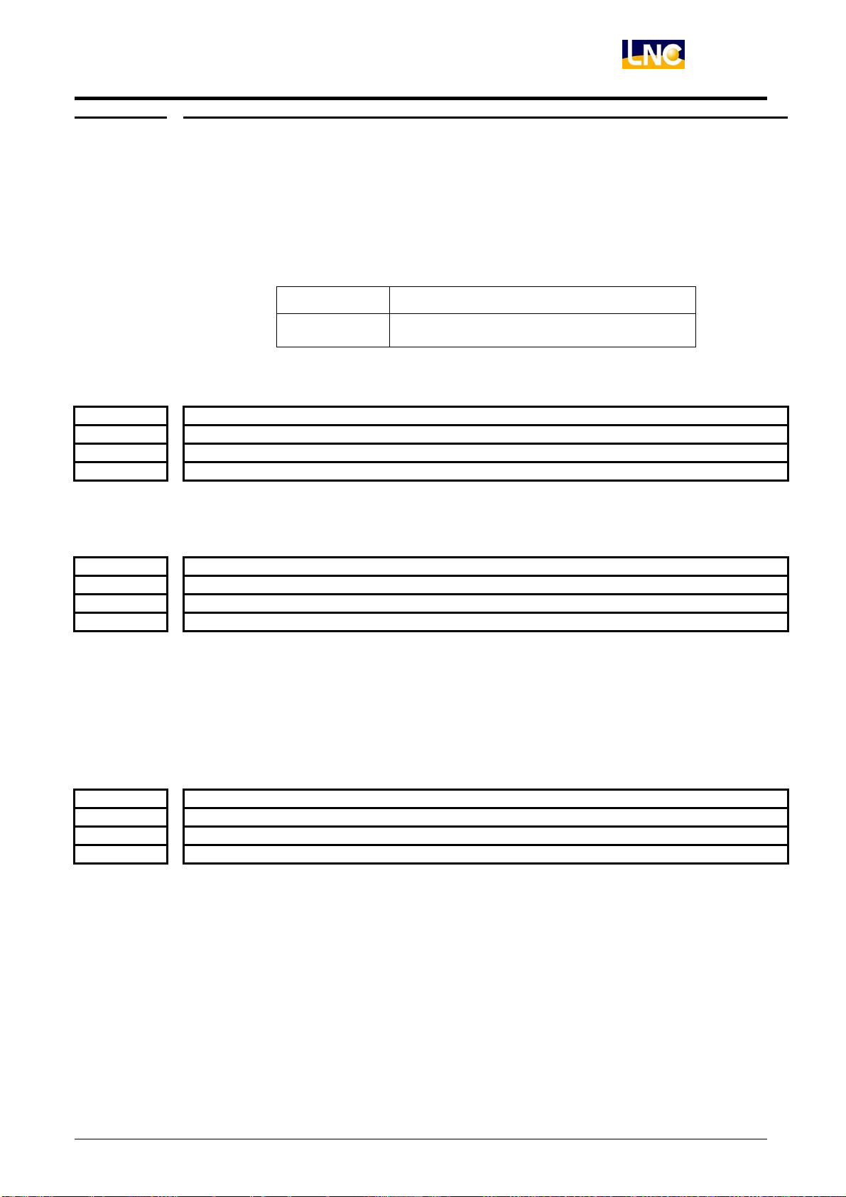
C Bit 059
C Bit 060
C Bit 061
C Bit 062
Description:
C Bit 066
C Bit 067
C Bit 068
C Bit 069
Description:
C Bit 075
C Bit 076
C Bit 077
C Bit 078
Description:
LNC-M600i
PLC Maintenance -- C,S Bits and Register
In JOG/RAPID or MPG mode, if the system warning message (OP 6001 ~ OP 6008) of PLC
travel limit occurs, it is okay not to remove the warning message. Just moving directly to the
reverse direction away from where the warning message occurs. After getting away from the
software limitation range, the warning message will be removed.
Under mode of MEM, MDI or HOME, if the system warning message (OP 6001 ~ OP 6008) of
PLC travel limit occurs, OP will send out the warning message. In this case, users must press
“RESET” to reset the system.
ALARM ID Warning Message
OP 1020 OVER PLC TRAVEL LIMIT
X Axis Interlock
Y Axis Interlock
Z Axis Interlock
4th Axis Interlock
When the corresponding axis is ON, the axis will NOT move. But, the coordinate value will be
renewed.
X Axis: Select Axis Direction Signal of Handle INT
Y Axis: Select Axis Direction Signal of Handle INT
Z Axis: Select Axis Direction Signal of Handle INT
4th Axis: Select Axis Direction Signal of Handle INT
Assumed NC is under MEM mode. User can use Manual Handle Interrupt function to
increase/decrease tool shifting amount in order to modify path. However, before using this
function, user must set Handle Interrupt axis selection signal and MPG ratio (R REGISTER
014). Then, user can use MPG to modify tool position. However, absolute coordinate will NOT
be modified by Handle Interrupt, there will be a OFFSET amount of the initial program path and
afterward tool path. This OFFSET amount will be cleared only by using manual reference point
return.
X Axis Servo Alarm
Y Axis Servo Alarm
Z Axis Servo Alarm
4th Axis Servo Alarm
This signal will notify system if motor driver of any axis has any extraordinary phenomenon.
LNC Technology Co., Ltd. 73
Page 80
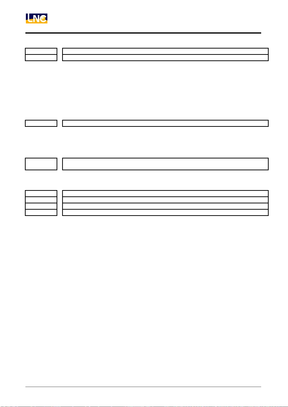
LNC-M600i
PLC Maintenance -- C,S Bits and Register
C Bit 082
C Bit 083
Description:
C Bit 085
Description:
C Bit 086
Description:
C Bit 089
C Bit 090
C Bit 091
C Bit 092
Description:
1st Spindle CW
1st Spindle CCW
When C bit of clockwise is ON, spindle rotates in clockwise direction.
When C bit of counter-clockwise is ON, spindle rotates in counter-clockwise direction.
If the above two are both OFF, spindle stops rotating.
Note 1: The above C bits are enabled in normal spindle speed control mode, which is spindle
clockwise, counter-clockwise and stop.
Note 2: If the spindle CW and CCW are controlled by inventor’s CW and CCW connection point
control, the above signals will only notify NC that the current spindle is in CW or CCW
condition.
Spindle Orientation
This signal will be enabled when spindle orientation is decided by encoder and in JOG mode.
Please notice that if Parameter # 0019, 1055, 1056 are not set for orientation position, spindle
will be re-orientated again.
Spindle Command Type Changes to Pulse Type Under Spindle Orientation and Ridig
Tapping Modes
Signal of Spindle is in orientation mode and also finishes orientating.
X Axis Mirror Image
Y Axis Servo Alarm
Z Axis Servo Alarm
4th Axis Servo Alarm
When mirror image signal is ON under Auto mode, this axis will be in reverse moving direction.
74
LNC Technology Co., Ltd.
Page 81
C Bit 097
C Bit 098
C Bit 099
Description:
LNC-M600i
PLC Maintenance -- C,S Bits and Register
1st Spindle Gear #1
1st Spindle Gear #2
1st Spindle Gear #3
Setting the gear ratio between spindle motor and spindle. Every spindle provides 4sets of
parameter # of gear ratio. The system default is to use the 4
modify other sets of gear ratio, user can select the suitable gear ratio from each spindle’s
corresponding gear ratio C bit.
Spindle Gear C bit
1 C97=ON
1st
Spindle
2 C98=ON
3 C99=ON
4 C97,98,99=OFF
1 C116=ON
2nd
Spindle
2 C117=ON
3 C118=ON
4 C116,117,118=OFF
1 C121=ON
3rd
Spindle
2 C122=ON
3 C123=ON
4 C121,122,123=OFF
th
set of gear ratio. If user want to
# of Motor
Tooth
Parameter #
0049
Parameter #
0051
Parameter #
0178
Parameter #
0181
Parameter #
0664
Parameter #
0666
Parameter #
0668
Parameter #
0670
Parameter #
0672
Parameter #
0674
Parameter #
0676
Parameter #
0678
# of Spindle
Tooth
Parameter #
0050
Parameter #
0052
Parameter #
0179
Parameter #
0182
Parameter #
0665
Parameter #
0667
Parameter #
0669
Parameter #
0671
Parameter #
0673
Parameter #
0675
Parameter #
0677
Parameter #
0679
LNC Technology Co., Ltd. 75
Page 82
LNC-M600i
PLC Maintenance -- C,S Bits and Register
C Bit 100
C Bit 101
C Bit 102
C Bit 103
C Bit 104
C Bit 105
C Bit 106
C Bit 107
C Bit 108
C Bit 109
C Bit 110
C Bit 111
C Bit 112
C Bit 113
C Bit 114
C Bit 115
Description:
C Bit 119
Description:
C Bit 120
Description:
C Bit 124
Description:
C Bit 125
Description:
C Bit 126
Description:
MACRO Variable $200
MACRO Variable $201
MACRO Variable $202
MACRO Variable $203
MACRO Variable $204
MACRO Variable $205
MACRO Variable $206
MACRO Variable $207
MACRO Variable $208
MACRO Variable $209
MACRO Variable $210
MACRO Variable $211
MACRO Variable $212
MACRO Variable $213
MACRO Variable $214
MACRO Variable $215
These signals are the same as the MACRO system variables $120~$135. They provide input
points of MACRO for LADDER. Example: If set UI0 to ON in LADDER, then $120 will be 1 in
MACRO. These MACRO input point signals will provide order determination for MACRO.
ZP2Z Down Cancel
When this signal is ON, the local Z axis motion will be inhibited after the 2
This signal is to protect tool exchanging and to prevent tool collusion after tool magazine moves
toward left.
PMC Axis Go
Setting this signal to ON in order to enable PMC axis moving command under the condition of
JOG mode and when all PMC axis moving data are ready.
Disable Sigal in Rigid Tapping
Milling disables rigid tapping.
Enable Signal in Rigid Tapping
Rigid tapping (M29). When this signal is on, Z axis moving amount will follow the spindle
encoder’s pulse amount. So user must use M28 to delete the signal when rigid tapping is done
in order to prevent any wrong motion from the system.
Enable Signal of Spindle Motor Rotates in Gear-Shfiting Speed
Milling spindle changes rotational speed.
nd
reference point.
76
LNC Technology Co., Ltd.
Page 83
C Bit 127
Description:
C Bit 134
Description:
C Bit 140
C Bit 141
C Bit 142
C Bit 143
C Bit 144
C Bit 145
C Bit 146
C Bit 147
Description:
LNC-M600i
PLC Maintenance -- C,S Bits and Register
Spindle Gear-Shifting Complete Signal
Milling gear-shifting completed signal.
Clear Working Piece Number
When NC reads M02, M30, the reading M code and parameter 89 are the same, NC will add
the working piece by 1. If the working piece number is larger than or equal to that of the
maximum working piece setting, NC will send out S134 to inform PLC to do the corresponding
motion. When PLC sends out C 134, NC will clear the working piece number to zero.
2nd +X Axis Software Limit Choice
2nd -X Axis Software Limit Choice
2nd +Y Axis Software Limit Choice
2nd -Y Axis Software Limit Choice
2nd +Z Axis Software Limit Choice
2nd -Y Axis Software Limit Choice
2nd +4th Axis Software Limit Choice
2nd -4th Axis Software Limit Choice
st
1
software limit: Using parameter 1006 ~ 1013 to set the limit. After executing zero return
procedure, the parameter setting value will be enabled. The booting default
value of +ive direction is 99999.999mm and the booting default value of –ive
nd
2
software limit: Using parameter 1034 ~ 1041to set the limit. After executing zero return
The corresponding C BIT of each axis can exchange any value between the 1st software limit
and the 2nd software limit. This means that only one set/combination can be enabled at tone
time within the limit of the 1
Software Limit C BIT
X axis +ive direction
software limit
X axis -ive direction
software limit
Y axis +ive direction
software limit
Y axis -ive direction
software limit
Z axis +ive direction
software limit
Z axis -ive direction
software limit
4th axis +ive direction
software limit
4th axis -ive direction
software limit
direction is -99999.999mm.
procedure, the parameter setting value will be enabled. The booting default
value of +ive direction is 99999.999mm and the booting default value of –ive
direction is -99999.999mm.
st
software limitation and the 2nd software limitation.
C140: When OFF, use 1
When ON, using 2
C141: When OFF, use 1
When ON, using 2
C142: When OFF, use 1
When ON, using 2
C143:When OFF, use 1
When ON, using 2
C144:When OFF, use 1
When ON, using 2
C145:When OFF, use 1
When ON, using 2
C146:When OFF, use 1
When ON, using 2
C147:When OFF, use 1
When ON, using 2
st
software limit;
nd
software limit.
st
software limit;
nd
software limit.
st
software limit;
nd
software limit.
st
software limit;
nd
software limit.
st
software limit;
nd
software limit.
st
software limit;
nd
software limit.
st
software limit;
nd
software limit.
st
software limit;
nd
software limit.
LNC Technology Co., Ltd. 77
Page 84
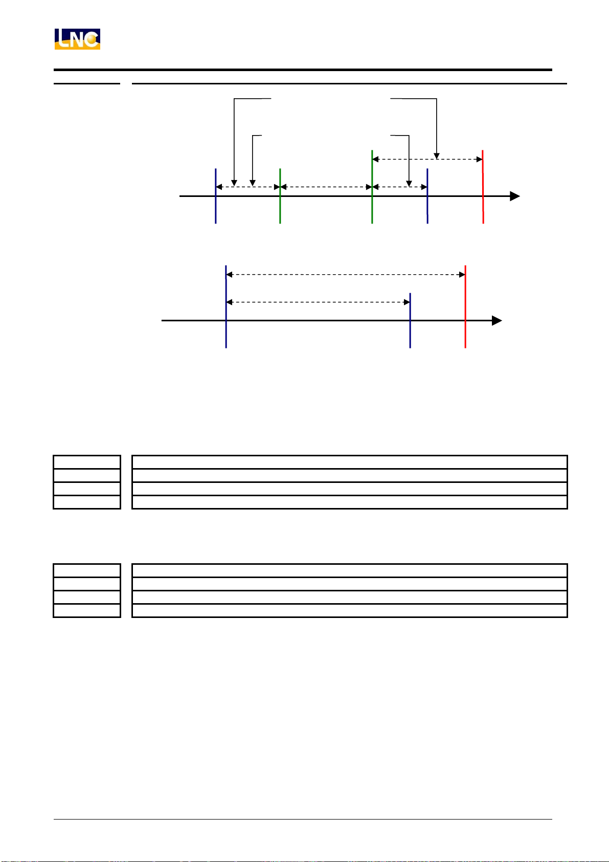
LNC-M600i
PLC Maintenance -- C,S Bits and Register
X axis Moving Range
(Para. # 0071 is 1、C129 is ON)
X axis Moving Range
(Para. # 0071 is 1、C129 is OFF)
C Bit 201
C Bit 202
C Bit 203
C Bit 204
Description:
C Bit 207
C Bit 208
C Bit 209
C Bit 210
Description:
- X axis
Direction G22
X axis Moving Range (C140
X axis Moving Range(C140 OFF)
+ X axis
Direction G22
+X
+ X axis
st
1
soft limit
G22 travel limit:Able to designated the embedded travel checking range. For Internal and
external prohibit area, use parameter 0071 to set the prohibit area for both internal and external
area. (0 means external prohibit area; 1 means internal prohibit area).
Absolute encoder Reset Ready Signal:X Axis
Absolute encoder Reset Ready Signal:Y Axis
Absolute encoder Reset Ready Signal:Z Axis
Absolute encoder Reset Ready Signal:4th Axis
When LADDER finishes absolute encoder zero return, this signal needs to be sent out to notify
NC that.
Absolute Encoder Data Ready Signal:X Axis
Absolute Encoder Data Ready Signal:Y Axis
Absolute Encoder Data Ready Signal:Z Axis
Absolute Encoder Data Ready Signal:4th Axis
LADDER will notify NC when driver enters into ABS transmitting mode and driver data are
ready.
78
LNC Technology Co., Ltd.
Page 85
A
C Bit 213
C Bit 214
C Bit 215
C Bit 216
Description:
C Bit 219
C Bit 220
C Bit 221
C Bit 222
Description:
C Bit 064
C Bit 065
Description:
LNC-M600i
PLC Maintenance -- C,S Bits and Register
Absolute Encoder Data Bit 0Transmitting Signal : X Axis
Absolute Encoder Data Bit 0Transmitting Signal : Y Axis
Absolute Encoder Data Bit 0Transmitting Signal : Z Axis
Absolute Encoder Data Bit 0Transmitting Signal : 4th Axis
Assumed absolute encoder data reading is sent by serial transmitting. Also, assumed 2 bits of
Encoder will be transmitted every time. So, when this bit is ON, it indicates that the signal of
transmitting 2 bits data from driver to NC is 1.
Absolute Encoder Bit 1 Transmit: X Axis
Absolute Encoder Bit 1 Transmit: Y Axis
Absolute Encoder Bit 1 Transmit: Z Axis
Absolute Encoder Bit 1 Transmit: 4th Axis
ssumed absolute encoder data reading is sent by serial transmitting. Also, assumed 2 bits of
Encoder will be transmitted every time. So, when this bit is ON, it indicates that the signal of
transmitting 2 bits data from driver to NC is 1.
PLC Window Read/Write Signal
PLC Commanding Signal
Please refer to 4.7 PLC Window structure for a detailed description.
LNC Technology Co., Ltd. 79
Page 86
LNC-M600i
PLC Maintenance -- C,S Bits and Register
4.5 S Bits Desctiption
S Bit 000
Description:
S Bit 001
Description:
S Bit 002
S Bit 003
S Bit 004
S Bit 005
S Bit 006
S Bit 007
S Bit 008
Description:
S Bit 010
Description:
S Bit 011
Description:
S Bit 016
S Bit 017
S Bit 018
S Bit 019
Description:
S Bit 020
S Bit 021
S Bit 022
S Bit 023
Description:
Cycle Start Light
When the system accepts to enable “CYCLE START” key and enters into automatic executing
condition, this signal is ON, which means the system is in the “Cycle Start” condition. This
signal is OFF when the automatic executing completed or the system is in ”FEED HOLD”
condition.
Feed Hold Light
When this signal is ON, it means the system is in ”FEED HOLD” condition. So the system is in
“Machine Stop” condition.
Edit Mode Light
MEM Mode Light
MDI Mode Light
JOG Mode Light
INC JOG Mode Light
MPG Mode Light
Home Mode Light
When these signals are ON, it means the system is in the relative operation mode condition.
Preparation Completed
When these signals are ON, the system is in “Preparation Complete” condition.
MDI keyboard press signal
1. The signal will be sent from system when pressing the bottom on MDI.
2. The signal notify PLC to turn on LCD power and recount time to turn off LCD power.
X 1st Axis Point Return End
Y 1st Axis Point Return End
Z 1st Axis Point Return End
4th 1st Axis Point Return End
When these signals are ON, it means the system relative axis completed the zero return
procedure and stop at the zero point.
X 2nd Axis Point Return End
Y 2nd Axis Point Return End
Z 2nd Axis Point Return End
4th 2nd Axis Point Return End
When these signals are ON, it means the system relative axis is completed the 2
th
4
) reference return procedure and stop at the 2nd (or 3rd, 4th) reference point.
nd
(or the 3rd,
80
LNC Technology Co., Ltd.
Page 87
S Bit 028
Description:
S Bit 029
Description:
S Bit 030
Description:
S Bit 031
Description:
S Bit 032
Description:
S Bit 033
Description:
S Bit 035
S Bit 036
S Bit 037
S Bit 038
Description:
LNC-M600i
PLC Maintenance -- C,S Bits and Register
Warning
When system warning occurs, this signal will notify PLC. After cause is eliminated, system
warning is off automatically and this signal is OFF.
M Code Read
When executing to the M code, this signal is “ON” in order to provide LADDER to do M code
executing until FIN signal replies back. Please refer to the description of M code end signal (C
BIT 038).
Distribution EndAlarm
In MEM or MDI mode, when the moving command interpolation is completed, this signal will be
sent out. So when M code and the moving G code are on the same BLOCK, please use this
signal to control and to execute M code after moving G code. If do not use this signal, M code
will be executed simultaneously with G code interpolation.
Alarm
When the system alarm is on, this signal is ON.
Reset
When the system receives the RESET command, this signal is ON. Remain one time scanning
time in order for LADDER to reset.
NC Ready
Assumed the controller’s power is on. After normally executing program, this signal will be ON.
MPG x1000 Ratio Speeding
MPG x1 Ratio Speeding
MPG x10 Ratio Speeding
MPG x100 Ratio Speeding
These four signals are used to indicate the current using MPG ratio.
MPG Ratio S035 S036 S037 S038
x1 0 1 0 0
x10 0 0 1 0
x100 0 0 0 1
x1000 1 0 0 0
S Bit 039
Description:
Program Restart
When system enters the Program Restart process, the state signal of Program Restart will be
enable(S39=ON), and will be disable when the system is completed or leave the operational
status of Program Restart.
LNC Technology Co., Ltd. 81
Page 88
LNC-M600i
PLC Maintenance -- C,S Bits and Register
S Bit 040
Description:
S Bit 041
Description: Conditional signal that is relative to Optional Block Skip(BDT).
S Bit 042
Description:
S Bit 043
Description: Conditional signal that is relative to Machine Lock(MLK).
S Bit 044
Description: Conditional signal that is relative to Optional Stop(OPS).
S Bit 045
Description: Conditional signal that is relative to Rapid Traverse(RT).
S Bit 046
Description: Conditional signal that is relative to Z Axis Cancel(ZNG).
S Bit 047
Description: Conditional signal that is relative to Auxiliary Function Lock(AFL).
S Bit 054
Description:
Single Block
Conditional signal that is relative to single block (SBK).
Optional Block Skip
Dry Run
Conditional signal that is relative to Dry Run (DRN).
Machine Lock
Optional Stop
Rapid Traverse
Z-Axis Neglect
Auxiliary Function Lock
S Code Read
When executing to S code, this signal is ON in order to provide LADDER to do S code
executing until FIN signal is sending back.
82
LNC Technology Co., Ltd.
Page 89
S Bit 061
Description:
S Bit 062
Description:
LNC-M600i
PLC Maintenance -- C,S Bits and Register
Z-Axis Neglect
ON/OFF control on the communication style software Panel will communicate with LADDER
through this signal. For Z-AXIS NEGLECT key on the software Panel, ON/OFF control will
communicate with LADDER through this signal. The timing procedure is as following:
S061
C045
S046
MPG Dry Run
ON/OFF control on the communication style software Panel will communicate with LADDER
through this signal. For MPG Dry Run key on the software Panel, ON/OFF control will
communicate with LADDER through this signal. The timing procedure is as following:
S Bit 063
Description:
S062
C020
S068
Auxiliary Function Lock
ON/OFF control on the communication style software Panel will communicate with LADDER
through this signal. For AUXILIARY FUNCTION LOCK key on the software Panel, ON/OFF
control will communicate with LADDER through this signal. The timing procedure is as
following:
S063
C046
S047
LNC Technology Co., Ltd. 83
Page 90
LNC-M600i
PLC Maintenance -- C,S Bits and Register
S Bit 068
Description: Conditional signal that is relative to MPG Dry Run(MPGDRN).
S Bit 069
Description:
S Bit 071
Description:
MPG Dry Run
T Code Read
When executing to T code, this signal is ON in order to provide LADDTER to do T code
executing until FIN signal is sending back.
Machine Lock
ON/OFF control on the communication style software Panel will communicate with LADDER
through this signal. For Machine Lock key on the software Panel, ON/OFF control will
communicate with LADDER through this signal. The timing procedure is as following:
S071
S Bit 072
Description:
C043
S043
Dry Run
ON/OFF control on the communication style software Panel will communicate with LADDER
through this signal. For Dry Run key on the software Panel, ON/OFF control will communicate
with LADDER through this signal. The timing procedure is as following:
S072
C042
S042
84
LNC Technology Co., Ltd.
Page 91
S Bit 073
Description:
S Bit 074
Description:
LNC-M600i
PLC Maintenance -- C,S Bits and Register
Optional Block Skip
ON/OFF control on the communication style software Panel will communicate with LADDER
through this signal. For Optional Block Skip key on the software Panel, ON/OFF control will
communicate with LADDER through this signal. The timing procedure is as following:
S073
C041
S041
Optional Stop
ON/OFF control on the communication style software Panel will communicate with LADDER
through this signal. For Optional Stop key on the software Panel, ON/OFF control will
communicate with LADDER through this signal. The timing procedure is as following:
S074
C044
S044
S Bit 080
S Bit 081
S Bit 082
S Bit 083
M00 Read
M01 Read
M02 Read
M30 Read
Description: M00:after interpreting as M00, this signal is ON(remain one time scanning time)
M01:after interpreting as M01, this signal is ON(remain one time scanning time)
M02:after interpreting as M02, this signal is ON(remain one time scanning time)
M30:after interpreting as M03, this signal is ON(remain one time scanning time)
S Bit 086
Description:
Orientation Finish
When spindle orientation is completed, this signal is ON. When PLC cancels the spindle
orientation command (C85), this signal will become OFF.
LNC Technology Co., Ltd. 85
Page 92
LNC-M600i
A
PLC Maintenance -- C,S Bits and Register
S Bit 088
Description:
S Bit 091
Description:
S Bit 092
Description:
S Bit 093
Description:
S Bit 094
Description:
S Bit 100
S Bit 101
S Bit 102
S Bit 103
S Bit 104
S Bit 105
S Bit 106
S Bit 109
S Bit 112
S Bit 113
S Bit 114
S Bit 115
Description:
S Bit 120
Description:
S Bit 128
Description:
1st Spindle Speed Arrival
This signal is ON when the spindle speed arrives to its designated speed. Parameter 1054 is to
set the error range of the spindle speed arrival.
Not in Canned Cycle Mode
ssumed the system is in Canned Cycle mode. If this signal is OFF, effective G code of Group
G09 is not 80. On the other hand, if the system is not under Canned Cycle mode and this signal
is ON, then the effective G code of Group G09 is 80.
Spindle Zero Speed Arrival
When the spindle rotational speed arrives to 0 rpm, the system will send out this signal and set
the arrival speed to 20 rpm in advance. Also, able to use parameter No. 1063 to set the
maximum speed when send out this signal.
Spindle Command Type Changes to Pulse Command in Spindle and Ridig Tapping Mode
NC notifies PLC spindle to get ready to switch to the position control mode. Meanwhile, driver
does the corresponding switch.
Spindle Motor Speed when Gears are Switched
This signal will be sent out when spindle reaches gear-shifting speed.
MACRO Variable $600
MACRO Variable $601
MACRO Variable $602
MACRO Variable $603
MACRO Variable $604
MACRO Variable $605
MACRO Variable $606
MACRO Variable $609
MACRO Variable $612
MACRO Variable $613
MACRO Variable $614
MACRO Variable $615
These signals are the MACRO system variables $600~$615, which are MACRO outputs to
LADDER point. Example: set $600 as 1 in MACRO, then UO0 will be ON in LADDER, which
means that MACRO output signals will be used as external control for LADDER.
PMC Axis Finish
This signal is ON when PMC axis moving is completed.
Riding Tapping Mode
NC notifies PLC that whether or not NC is in rigid tapping mode.
86
LNC Technology Co., Ltd.
Page 93
S Bit 130
S Bit 131
S Bit 132
S Bit 133
X Axis Moving
Y Axis Moving
Z Axis Moving
4th Axis Moving
Description: Moving condition of each axis:
ON:Moving;
OFF:Stop.
S Bit 134
Description:
Max Working Piece Arrival
When the number of working piece is greater than or equal to that of the maximum
setting-working piece, S134 will be sent out to inform PLC. If setting the maximum working
piece to zero, then this signal will not be sent out. PLC will use C134 to inform NC to clear
working piece.
Application Description:
Enter into user parameter to do function selection and set parameter No. 12 as 1. When the
working piece number reaches the setting working piece number, it will enter into the Feed Hole
condition and send out warning message (Wrokpiece is full).
At this time, user can do any needed motion. If there is no need to do any other motion, please
press “Cycle Start” key directly. Then the working piece number will be cleared to zero
automatically. Furthermore, it will start working automatically and counting working piece
number from zero. If no need this function at all, then set parameter No.12 as 0. Circulating
work of working piece will not be affected.
01 Program Editing 0 11 Power Off Delay Time 5
02 Home Point Search Priority 1 12 Work Piece Alarm 1
03 Return Home Axis Priority 1 13
04 Rapidly Moving 50% 0 14
05 Total Number of Turret 0 15
06 Safety Door 0 16
07 Enforce Track Lubrication 0 17
08 Lubricate ON Time 5 18
09 Lubricate OFF Time 30 19
10 Auto Power Off Function 1 20
S Bit 150
S Bit 151
S Bit 152
S Bit 153
Description:
Request Signal of Spindle Gear-Shifting: 1st Gear
Request Signal of Spindle Gear-Shifting: 2nd Gear
Request Signal of Spindle Gear-Shifting: 3rd Gear
Request Signal of Spindle Gear-Shifting: 4th Gear
When S code is not below into the current gear range, System will use S Bit to notify PLC to
execute gear shifting:
S Bit 150:1
S Bit 151:2
S Bit 152:3
S Bit 153:4
st
spindle gear shifting signal;
nd
spindle gear shifting signal;
rd
spindle gear shifting signal;
th
spindle gear shifting signal;
At this time, spindle output voltage remains the same.
LNC-M600i
PLC Maintenance -- C,S Bits and Register
LNC Technology Co., Ltd. 87
Page 94
LNC-M600i
PLC Maintenance -- C,S Bits and Register
S Bit 154
S Bit 155
S Bit 156
S Bit 157
S Bit 158
S Bit 159
Description:
S Bit 201
S Bit 202
S Bit 203
S Bit 204
Description:
S Bit 207
S Bit 208
S Bit 209
S Bit 210
Description:
S Bit 213
S Bit 214
S Bit 215
S Bit 216
Description:
S Bit 079
Description:
X Axis Moving Direction
Y Axis Moving Direction
Z Axis Moving Direction
4th Axis Moving Direction
5th Axis Moving Direction
6th Axis Moving Direction
These S BITs express the moving direction of each axis, when axis is at moving state.
ON:positive direction
OFF:negative direction
Enter into Absolute Encoder Data Transmitting Mode:X Axis
Enter into Absolute Encoder Data Transmitting Mode:Y Axis
Enter into Absolute Encoder Data Transmitting Mode:Z Axis
Enter into Absolute Encoder Data Transmitting Mode:4th Axis
To use this signal to notify servo driver to enter into ABS transmitting mode.
Absolute Encoder Data Transmitting:X Axis
Absolute Encoder Data Transmitting:Y Axis
Absolute Encoder Data Transmitting:Z Axis
Absolute Encoder Data Transmitting:4th Axis
To use this signal to request ABS transmitting from servo driver.
Absolute Encoder Reset:X Axis
Absolute Encoder Reset:Y Axis
Absolute Encoder Reset:Z Axis
Absolute Encoder Reset:4th Axis
To use this signal to notify servo driver to eliminate absolute Encoder zero return motion.
PLC Window Finish
Please refer to 4.7 PLC Window structure for a detailed description.
88
LNC Technology Co., Ltd.
Page 95
4.6 Register Desctiption
LNC-M600i
PLC Maintenance -- C,S Bits and Register
R Bit 001
Description:
R Bit 002
Description:
R Bit 003
Description:
R Bit 004
Description:
R Bit 013
Description:
M0~M99, M Code Command
Executing M code will send the content of M code through this register.
Range:00 ~ 99
S000~S9999, S Code Command
Executing S code will send the content of S code through this register.
Range:0000 ~ 9999。
T000~T9999, T Code Command
Executing T code will send the content of T code through this register.
Range:0000 ~ 9999.
Spindle Actual Speed
Actually rotational speed of spindle
Mode Select
The definition of operating-mode register is showed on table,
Operating Mode REG 013
EDIT 1
MEM 2
MDI 3
JOG
RAPID
INCJOG 5
MPG 6
HOME 7
4 (C23=OFF)
4 (C23=ON )
LNC Technology Co., Ltd. 89
Page 96
LNC-M600i
PLC Maintenance -- C,S Bits and Register
R Bit 014
Description:
MPG Ratio Select
The definition of register of MPG amplification is showed on table,
MPG amplification REG 014
x1
1(or others)
x10 2
x100 3
R Bit 015
Spindle Rotaing Mode Override
Description: The definition of register of modulating spindle's rotational speed is showed on table,
% REG 015
0% 0
10% 1
20% 2
30% 3
40% 4
50% 5
60% 6
70% 7
80% 8
90% 9
100% 10
110% 11
120% 12
1% others
90
LNC Technology Co., Ltd.
Page 97
R Bit 016
Description:
PLC Maintenance -- C,S Bits and Register
ATC Mode Feedrate Override
The definition of register of modulating cutting-feedrate is showed on table,
% REG 016
0% 0
10% 1
20% 2
30% 3
40% 4
50% 5
60% 6
70% 7
80% 8
90% 9
100% 10
110% 11
120% 12
130% 13
140% 14
150% 15
160% 16
170% 17
180% 18
190% 19
200% 20
‰ others
LNC-M600i
LNC Technology Co., Ltd. 91
Page 98
LNC-M600i
PLC Maintenance -- C,S Bits and Register
R Bit 017
Description:
JOG Mode Feedrate Override
The definition of register of modulating manual feedrate is showed on table,
% REG 017
0% 0
10% 1
20% 2
30% 3
40% 4
50% 5
60% 6
70% 7
80% 8
90% 9
100% 10
110% 11
120% 12
130% 13
140% 14
150% 15
160% 16
170% 17
180% 18
190% 19
200% 20
‰ others
92
LNC Technology Co., Ltd.
Page 99
R Bit 018
Description:
R Bit 021
Description:
R Bit 022
Description:
R Bit 024
R Bit 025
R Bit 026
R Bit 027
R Bit 028
R Bit 029
R Bit 030
R Bit 031
Description:
LNC-M600i
PLC Maintenance -- C,S Bits and Register
Rapid Traverse Mode Feedrate Override
The definition of register of rapidly modulating feedrate,
% REG 18
F0% 0
F0% 1
25% 2
50% 3
100% 4
1% others
P. S :The actual rapid-feedrate is decided in parameter 0040 when REG18 is F0%.
PMC Feedrate
Setting the feedrate of PMC axis.
PMC Control
Setting PMC controlled axis.
Bit 1,Bit 0:00 for G00,01 for G01,10 for G53
Bit 2:1 for spindle
Bit 3:Reserved
Bit 4:1 for X axis
Bit 5:1 for Y axis
Bit 6:1 for Z axis
Bit 7:1 for 4
PMC Function of X-Axis Command Amount, Unit=mm
PMC Function of X-Axis Command Amount, Unit=um
PMC Function of Y-Axis Command Amount, Unit=mm
PMC Function of Y-Axis Command Amount, Unit=um
PMC Function of Z-Axis Command Amount, Unit=mm
PMC Function of Z-Axis Command Amount, Unit=um
PMC Function of 4th-Axis Command Amount, Unit=mm
PMC Function of 4th-Axis Command Amount, Unit=um
When setting PMC axis to execute moving command, the designated moving distance must be
divided into two parts, which one is mm part and the other is um part, and be set into each
register separately.
th
axis
LNC Technology Co., Ltd. 93
Page 100
LNC-M600i
PLC Maintenance -- C,S Bits and Register
R Bit 040
R Bit 041
R Bit 042
R Bit 043
R Bit 044
R Bit 045
Description:
R Bit 060
R Bit 061
R Bit 062
R Bit 063
R Bit 064
R Bit 065
R Bit 066
R Bit 067
R Bit 068
R Bit 069
R Bit 070
R Bit 071
R Bit 072
R Bit 073
R Bit 074
Description:
PLC Alarm Message
PLC Alarm Message
PLC Alarm Message
PLC Alarm Message
PLC Alarm Message
PLC Alarm Message
The driver signal of alarm message provides PLC LADDER to send out alarm. There are six
registers(word),and the sum of 96 messages can provide definitions and drivers. For
example, LADDER must put a constant 5 into R40 with moving command(MOV). The strings
of message must define at corresponding position in ENC_MLC.ERR simultaneously. In the
same way, if setting R40 for zero, PLC ALARM will be cleaned.
PLC Windows Function for Item Code
PLC Windows Function for Sub Item Code 1
PLC Windows Function for Sub Item Code 2
NC Overwrited PLC Window Function 1
NC Overwrited PLC Window Function 2
NC Overwrited PLC Window Function 3
NC Overwrited PLC Window Function 4
NC Overwrited PLC Window Function 5
NC Overwrited PLC Window Function 6
NC Overwrited PLC Window Function 7
NC Overwrited PLC Window Function 8
NC Overwrited PLC Window Function 9
NC Overwrited PLC Window Function 10
NC Overwrited PLC Window Function 11
NC Overwrited PLC Window Function 12
Please refer to 4.7 PLC Window structure for a detailed description.
94
LNC Technology Co., Ltd.
 Loading...