


V18AUMLA1210A
LITTELFUSE V18AUMLA1210A, V18AUMLA1206WT, V18AUMLA1206WH, V18AUMLA1206WA, V18AUMLA1206H Datasheet
...
Surface Mount Varistors
158
www.littelfuse.com
Multilayer Transient Voltage Surge Suppressor
AUML Varistor Series
The AUML Series of Multilayer Transient Surge Suppressors was specifi-
cally designed to suppress the destructive transient voltages found in an
automobile. The most common transient condition results from large
inductive energy discharges. The electronic systems in the automobile,
e.g. antilock brake systems, direct ignition systems, engine control,
airbag control systems, wiper motor controls, etc., are susceptible to
damage from these voltage transients and thus require protection. The
AUML transient suppressors have temperature independent suppression
characteristics affording protection from -55
o
C to 125
o
C.
The AUML suppressor is manufactured from semiconducting ceramics
which offer rugged protection and excellent transient energy absorption
in a small package. The devices are available in ceramic leadless chip
form, eliminating lead inductance and assuring fast speed of response to
transient surges. These Suppressors require significantly smaller space
and land pads than silicon TVS diodes, offering greater circuit board
layout flexibility for the designer.
Also see the Littelfuse ML, MLN and MLE Series of Multilayer Suppressors.
Features
• Load Dump Energy Rated per SAE Specification J1113
• Leadless, Surface Mount Chip Form
• “Zero” Lead Inductance
• Variety of Energy Ratings Available
• No Temperature Derating up to 125
o
C Ambient
• High Peak Surge Current Capability
• Low Profile, Compact Industry Standard Chip Size; (1206, 1210,
1812 and 2220 Sizes)
• Inherent Bidirectional Clamping
• No Plastic or Epoxy Packaging Assures Better than 94V-0
Flammability Rating
AUML Varistor Series
Surface Mount Varistors
Multilayer Transient Voltage Surge Suppressor
159
www.littelfuse.com
3
SURFACE MOUNT
VARISTORS
Absolute Maximum Ratings For ratings of individual members of a series, see Device Ratings and Specifications chart
Continuous:
Steady State Applied Voltage:
DC Voltage Range (V
M(DC)
) . . . . . . . . . . . . . . . . . . . . . . . . . . . . . . . . . . . . . . . . . . . . . . . . . . . . . . . . . . . . . . . . . . . . . . . . . 18 V
Transient:
Load Dump Energy, (W
LD
) . . . . . . . . . . . . . . . . . . . . . . . . . . . . . . . . . . . . . . . . . . . . . . . . . . . . . . . . . . . . . . . . . . . . . . . . 1.5 to 25 J
Jump Start Capability (5 minutes), (V
JUMP
) . . . . . . . . . . . . . . . . . . . . . . . . . . . . . . . . . . . . . . . . . . . . . . . . . . . . . . . . . . . . . 24.5 V
Operating Ambient Temperature Range (T
A
). . . . . . . . . . . . . . . . . . . . . . . . . . . . . . . . . . . . . . . . . . . . . . . . . . . . . . . . . . . . . -55 to 125
O
C
Storage Temperature Range (T
STG
) . . . . . . . . . . . . . . . . . . . . . . . . . . . . . . . . . . . . . . . . . . . . . . . . . . . . . . . . . . . . . . . . . . -55 to 150
O
C
Temperature Coefficient (αv) of Clamping Voltage (V
C
) at Specified Test Current . . . . . . . . . . . . . . . . . . . . . . . . . . . . . . . . . . . <0.01 %/
O
C
CAUTION: Stresses above those listed in “Absolute Maximum Ratings” may cause permanent damage to the device. This is a stress only rating and operation of the device
at these or any other conditions above those indicated in the operational sections of this specification is not implied.
Device Ratings and Specifications
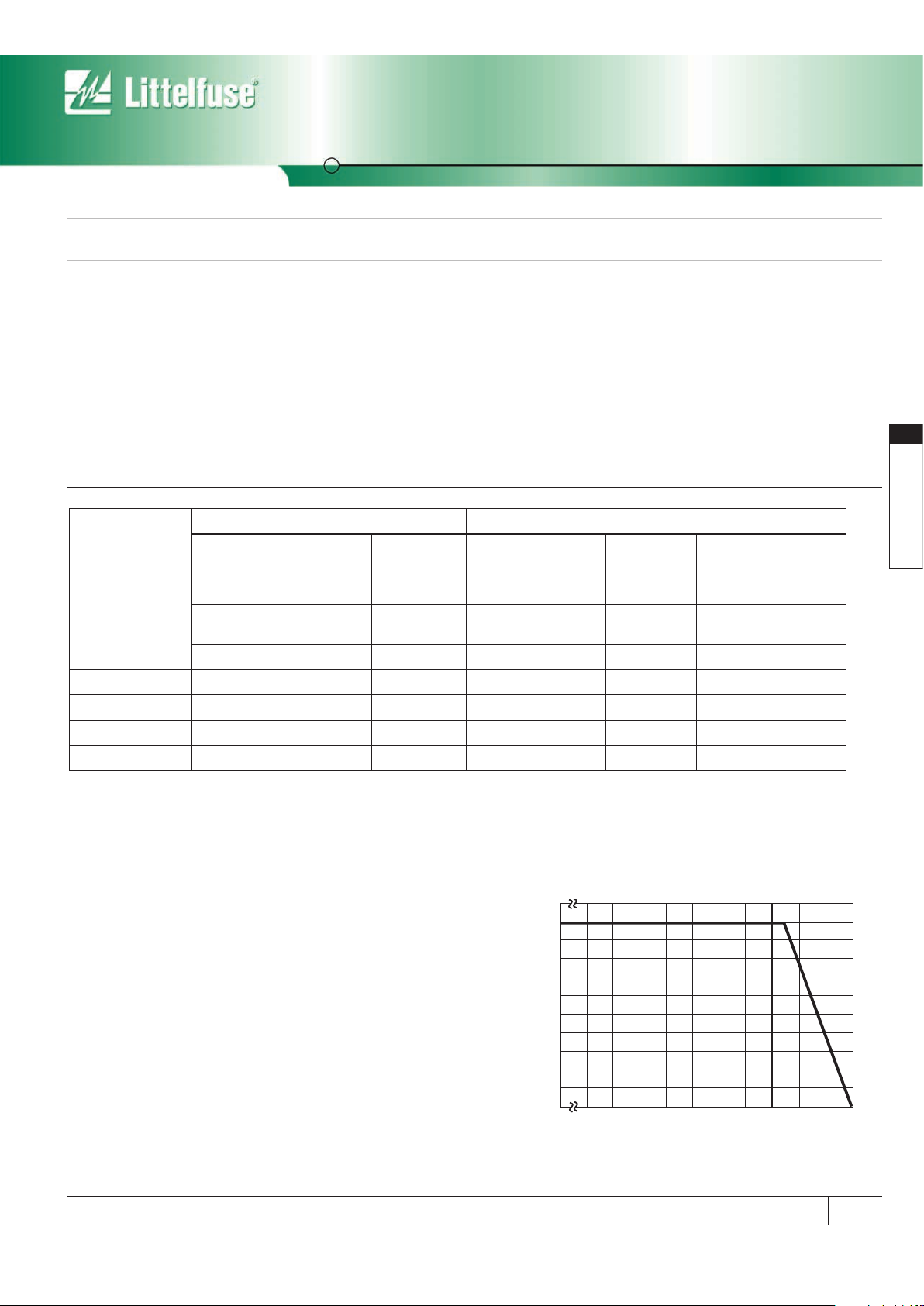
Power Dissipation Ratings
When transients occur in rapid succession, the average power dissipa-
tion is the energy (watt-seconds) per pulse times the number of pulses
per second. The power so developed must be within the specifications
shown on the Device Ratings and Characteristics table for the specific
device. Certain parameter ratings must be derated at high temperatures
as shown in Figure 1.
AUML SERIES UNITS
PA RT
NUMBER
MAXIMUM RATINGS (125
o
C) SPECIFICATIONS (25
o
C)
MAXIMUM
CONTINUOUS
DC VOLTAGE
JUMP
START
VO LTAGE
(5 MIN)
LOAD DUMP
ENERGY
(10 PULSES)
NOMINAL VARISTOR
VOLTAGE AT 10mA
DC TEST CURRENT
MAXIMUM
STANDBY
LEAKAGE
(AT 13V DC)
MAXIMUM CLAMPING
VOLTAGE (V
C
)
AT TEST CURRENT
(8/20ms)
V
M(DC)
V
JUMP
W
LD
V
N(DC)
MIN
V
N(DC)
MAX I
L
V
C
I
P
(V) (V) (J) (V) (V) (mA) (V) (A)
V18AUMLA1206 18 24.5 1.5 23 32 50 40 1.5
V18AUMLA1210 18 24.5 3 23 32 50 40 1.5
V18AUMLA1812 18 24.5 6 23 32 100 40 5
V18AUMLA2220 18 24.5 25 23 32 200 40 10
NOTES:
1. Average power dissipation of transients not to exceed 0.1W, 0.15W, 0.3W and 1W for model sizes 1206, 1210, 1812 and 2220 respectively.
2. Load dump energy rating (into the suppressor) of a voltage transient with a resultant time constant of 115ms to 230ms.
3. Thermal shock capability per Mil-Std-750, Method 1051: -55
o
C to 125
o
C, 5 minutes at 25
o
C, 25 Cycles: 15 minutes at each extreme.
4. For application specific requirements, please contact Littelfuse.
For automotive 24V and 42V applications please contact your Littelfuse representative or visit www.littelfuse.com for the latest product update.
FIGURE 1. CURRENT, ENERGY AND POWER DERATING
CURVE
100
90
80
70
60
50
40
30
20
10
0
-55 50 60 70 80 90 100 110 120 130 140 150
PERCENT OF RATED VALUE
AMBIENT TEMPERATURE (
o
C)
Multilayer Transient Voltage Surge Suppressor
AUML Varistor Series
Surface Mount Varistors
160
www.littelfuse.com
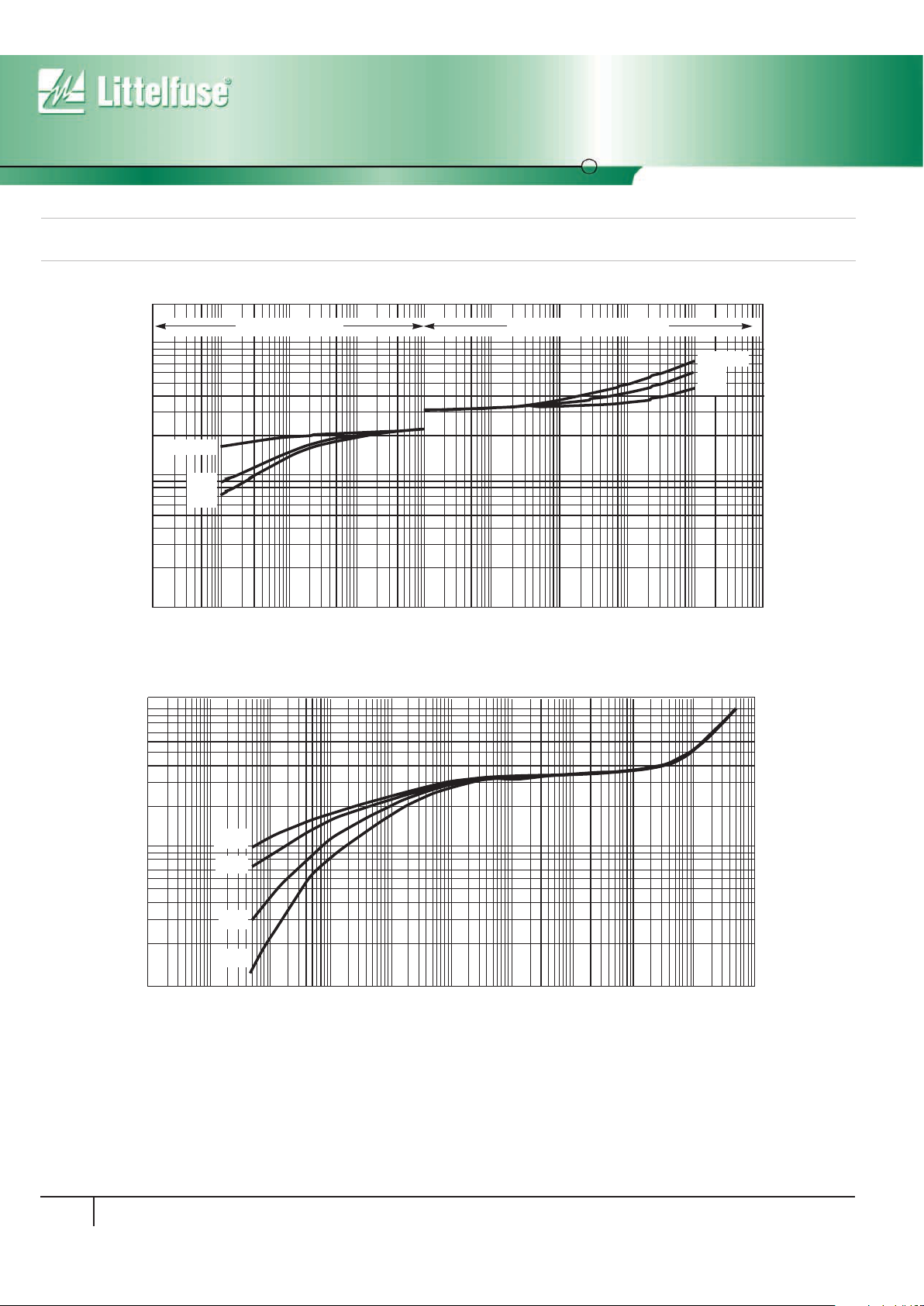
Temperature Effects
In the leakage region of the AUML suppressor, the device characteristics
approaches a linear (ohmic) relationship and shows a temperature
dependent affect. In this region the suppressor is in a high resistance
mode (approaching 10
6
Ω) and appears as a near open-circuit. Leakage
currents at maximum rated voltage are in the microamp range. When
clamping transients at higher currents (at and above the ten milliamp
V-I Characteristics Curves
range), the AUML suppressor approaches a 1-10 characteristic. In
this region the characteristics of the AUML are virtually temperature
independent. Figure 3 shows the typical effect of temperature on the
V-I characteristics of the AUML suppressor.
FIGURE 2. MAXIMUM LEAKAGE CURRENT/CLAMPING VOLTAGE CURVE FOR AUML SERIES AT 25
o
C
FIGURE 3. TYPICAL V-I CHARACTERISTICS OF THE V18AUMLA2220 at -40
o
C, 25
o
C, 85
o
C AND 125
o
C
VO LTAG E
100
1
1mA
10mA
100mA
1A 10A
100A
CURRENT
100mA10mA
10
1210/1206
1812
2220
MAXIMUM LEAKAGE MAXIMUM CLAMPING VOLTAGE
1210/1206
1812
2220
100
10
1
VO LTAG E
1mA 100mA10mA
1mA
-40
o
C
25
o
C
85
o
C
10mA 100mA 1A 10A 100A 1000A
CURRENT
125
o
C
 Loading...